Article

Analysis of Artifacts Caused by Pulse Imperfections in CPMG Pulse Trains in NMR Relaxation Dispersion Experiments

1
Graduate School of Medical Life Science, Yokohama City University, 1-7-29 Suehiro-cho, Tsurumi-ku, Yokohama 230-0045, Japan
2
Bruker Japan K.K., Osaka Office, 1-8-29 Nishimiyahara, Yodogawa-ku, Osaka-shi, Osaka 532-0004, Japan
*
Author to whom correspondence should be addressed.
Magnetochemistry 2018, 4(3), 33; https://doi.org/10.3390/magnetochemistry4030033
Submission received: 28 June 2018 / Revised: 25 July 2018 / Accepted: 26 July 2018 / Published: 30 July 2018

Abstract

:
Nuclear magnetic resonance relaxation dispersion (rd) experiments provide kinetics and thermodynamics information of molecules undergoing conformational exchange. Rd experiments often use a Carr-Purcell-Meiboom-Gill (CPMG) pulse train equally separated by a spin-state selective inversion element (U-element). Even with measurement parameters carefully set, however, parts of 1H–15N correlations sometimes exhibit large artifacts that may hamper the subsequent analyses. We analyzed such artifacts with a combination of NMR measurements and simulation. We found that particularly the lowest CPMG frequency (νcpmg) can also introduce large artifacts into amide 1H–15N and aromatic 1H–13C correlations whose 15N/13C resonances are very close to the carrier frequencies. The simulation showed that the off-resonance effects and miscalibration of the CPMG π pulses generate artifact maxima at resonance offsets of even and odd multiples of νcpmg, respectively. We demonstrate that a method once introduced into the rd experiments for molecules having residual dipolar coupling significantly reduces artifacts. In the method the 15N/13C π pulse phase in the U-element is chosen between x and y. We show that the correctly adjusted sequence is tolerant to miscalibration of the CPMG π pulse power as large as ±10% for most amide 15N and aromatic 13C resonances of proteins.

1. Introduction

Relaxation dispersion (rd) experiments of nuclear magnetic resonance (NMR) are one of the most commonly used methods to obtain valuable information about the kinetics and thermodynamics of molecules for which the conformations exchange between those in the major-populated visible state and in the minor-populated invisible state or among more conformational sub-states [1,2,3,4]. Recent developments of high-power rd experiments enable motions as fast as 4 μs to be detected [5,6,7,8]. Experiments intended for molecules with such characters provide effective transverse relaxation rates (R2eff) that depend on the field strength of the spin-lock [9] or on the repetition rate of refocusing π pulses in Carr-Purcell-Meiboom-Gill (CPMG) pulse trains [10,11] {δπδ}n, where δ, π, and n represent a delay, the π refocusing pulse between them, and the repeat count of spin echoes, respectively. The dependency plots a dispersion profile of R2eff for each observed spin. However, obtaining smooth dispersion curves with minimum artifacts in practice requires careful calibration of some measurement parameters [12,13].
In 15N spin rd experiments, the most frequently used method is a relaxation compensated (rc) CPMG pulse sequence, originally proposed by Loria et al. [14,15]. The pulse sequence contains two CPMG relaxation periods of equal and constant lengths without accompanied 1H decoupling (Figure 1a). The two periods are separated by a sequence basically composed of 1/(41JHN)–πH/πN–1/(41JHN)–πH, referred to hereafter as U-element, where πH/πN represent π pulses applied simultaneously to 1H and 15N spins, respectively. The former (CPMG1) and latter (CPMG2) pulse trains begin by targeting 15N spin transverse coherences that are, respectively, anti-phase 2NyHz, and in-phase Nx with respect to the coupled 1H spins through the 1JHN coupling constant according to the CPMG pulse phases in an example shown in Figure 1a. Since the anti-phase and in-phase coherences evolve by the 1JHN coupling and exchange with each other during the intervals between consecutive refocusing π pulses (2δ), the mixture ratio between the two coherences depends on δ as far as either the CPMG1 or CPMG2 period alone is concerned. Anti-phase coherences tend to relax faster than the corresponding in-phase coherences, owing to additional dipolar interactions between the coupled 1H spin and nearby surrounding 1H spins by means of mutual spin flip-flops. As a result, even molecules having no exchange exhibit R2eff that depends on δ. To overcome this problem, anti–phase coherences in CPMG1 are converted to the associated in-phase ones by the U-element placed between the two CPMG periods [14,15] (Figure 1b–g). Consequently, the total integrated periods as being experienced by the anti-phase and in-phase coherences are equalized. Namely, the differential relaxation rates of the in-phase and anti-phase coherences are averaged in the frame of average Hamiltonian theory [16], and the exchange rate (Rex) alone becomes dependent on the repetition rate of the refocusing π pulses. The conversion from 15N anti-phase to in-phase coherences corresponds to spin state-selective inversion of either one magnetization component of the 15N doublet, Nx/yHα or Nx/yHβ, where α and β stand for the spin-states of the coupled amide 1H spin [17]. The U-element, therefore, can also be expressed as canceling the cross-relaxation between the Nx/yHα and Nx/yHβ coherences.
In rc heteronuclear transverse relaxation optimized spectroscopy (TROSY)-based CPMG experiments [18], a false large R2eff is often observed, particularly at low repetition rates of the CPMG refocusing π pulses, even when the radio frequency (rf) magnetic field strength of the 15N or 13C π pulses is accurately calibrated. Such a large R2eff derives from the small peaks compared to those that should be properly observed in the two-dimensional (2D) 1H–15N or 1H–13C correlation spectra obtained at the corresponding CPMG frequency (νcpmg = 1/(4δ)). The lowest repetition rate is achieved by placing a single spin-echo in each side of the U-element in the rc CPMG pulse train. It is well known that a CPMG pulse train composed of even-numbered spin-echoes with the same π pulse phase has a property of canceling some artifacts caused by pulse imperfections [19]. However, as one is an odd number, artifacts are not compensated within each CPMG period alone. Furthermore, rd profiles carrying large artifacts only at CPMG frequencies corresponding to odd numbers of spin-echoes may look similar to the profiles of spin systems exchanging slowly on the NMR chemical shift time scale. Such slow exchange exhibits damped oscillation patterns in the low νcpmg range of the rd curves that can be approximated by sinc functions [20]. Consequently, such artifacts may lead to incorrect information regarding the dynamics of the molecules being observed.
Vallurupalli et al. [21] presented a method for accurately measuring the amide 15N spin rd of the respective TROSY and anti-TROSY magnetization components that are split along the 15N dimension by the 1JHN scalar coupling and the 1DHN residual dipolar coupling (RDC) for each amide resonance of protein molecules aligned along a static magnetic field in an alignment medium. To estimate RDC values for transiently populated conformations in minor states, they proposed a modified rc CPMG pulse sequence, which contained another pulse sequence, referred to as P-element hereafter, instead of the U-element. The P-element is different from the U-element in that the former has 15N π/2 pulses at both ends ((π/2)N–1/(41JHN)–πH/πN–1/(41JHN)–(π/2)N/πH). The first π/2 pulse is applied along ±y axes at the beginning of the P-element and the other one is applied along ±x axes at the end of the period without the receiver phase inverted. These π/2 pulses are necessary to remove unwanted magnetization generated by evolution by the sum of the scalar coupling (1JHN) and non-uniform residual dipolar coupling (1DHN) constants for samples aligned along the static magnetic field. As described in detail later, the difference is not strongly related to artifact suppression, as far as the observed systems are isotropic with no RDC. In the specific rc CPMG pulse sequence, they also introduced a smart way of minimizing artifacts. By adjusting the phase of the 15N π pulse in the P-element, artifacts accumulated in the CPMG1 period can be compensated for in the CPMG2 period for either the TROSY or anti-TROSY magnetization component. Thus, artifacts are canceled, even when an odd number of spin-echoes are placed in each CPMG period, as if the two CPMG pulse trains were tightly arranged for the total number of spin-echoes to be even.
With knowledge of the theory, we rather focused on the detailed analysis of how artifacts are generated in rc CPMG experiments. The combination of our NMR experiments and simulation has clarified the reasons for the following phenomena. Artifacts are often observed at the lowest νcpmg (n = 1). They appear even in peaks resonating near the S spin carrier frequency. They do not linearly increase with the offset frequency, unlike general intuition. They can often disappear by just shifting the carrier frequency by as small as tens of hertz. Peak intensities in rc CPMG experiments are vulnerable to artifacts unlike those in the R2 relaxation measurement experiments in popular R1, R2, {1H}–15N-nuclear Overhauser effect (NOE) analyses [22]. We here demonstrate that the method once introduced into the rd experiments for molecules having RDC [21,23] can also be applied to molecules with normal isotropic tumbling in order to significantly reduce unexpectedly large artifacts on R2eff, which may hamper further analyses. The correct U-element also tolerates miscalibration of the rf magnetic field strength of the CPMG π pulses with a deviation as large as ±10%. The method is effective for suppressing such artifacts against the pulse miscalibration and off-resonance effects not only in 15N TROSY rd CPMG experiments but also for the corresponding aromatic 13C experiments. Our simulation showed that the off-resonance effect and pulse miscalibration generated artifacts at distinct off-resonance positions. This method is immediately and easily implementable in a wide range of rc CPMG sequences, but it must be noted that the correct phase of the central π pulse in the U- or P-element is different depending on the spectrometer designs. The above-mentioned mechanisms are illustrated by a vector model, which may explain them more easily and intuitively than the average Hamiltonian-based calculation.

2. Results

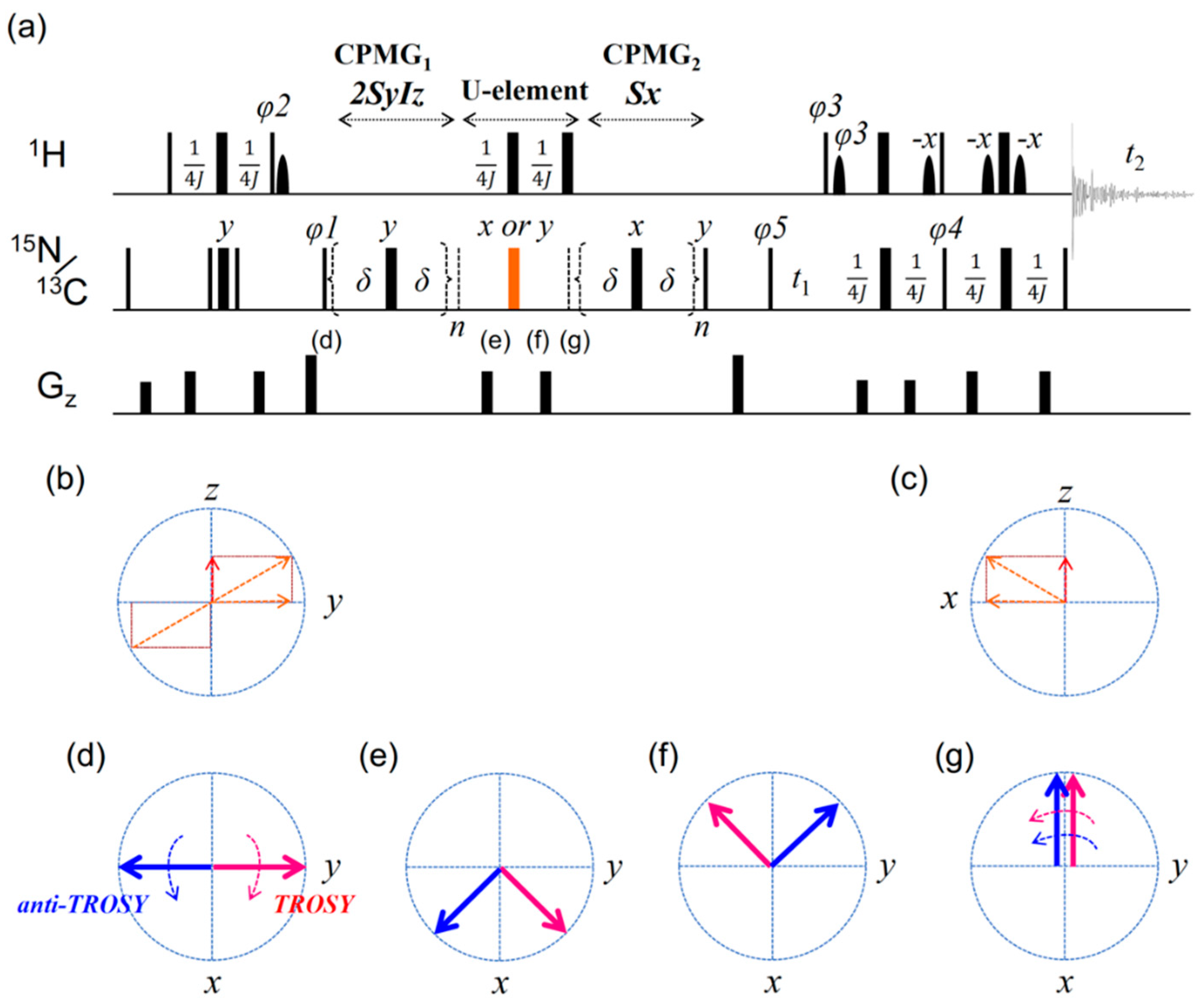
2.1. Artifacts Observed in Amide 15N Spin rd Experiments

To see the influence of possible miscalibration and off-resonance effects of CPMG refocusing π pulses on the measured rd profiles, we used a small and stable protein ChiA1, for which no significant supra-millisecond conformational exchange was found in a previous 15N spin relaxation analysis [24]. Figure 2a shows the rd profiles of Lys–673 as a typical example, obtained by a TROSY-based rc 15N spin CPMG pulse sequence without 1H continuous-wave decoupling during a pair of CPMG periods [21]. When the 15N π pulse in the middle of the U-element was applied with phase y, almost all the amide resonances exhibited flat rd profiles, as shown with the red profile in Figure 2a. This result is consistent with the observation that ChiA1 underwent no supra-millisecond significant conformational exchange. However, when the 15N π pulse of the U-element was applied along the axis shifted by 90° (i.e., x), large artificial R2eff values were found as shown in the blue profile in Figure 2a, particularly at the lowest νcpmg value (25 Hz), where a single 15N spin-echo was placed within each CPMG period (δ = 10 ms, the total relaxation time, 4*δ, = 40 ms). The 1H/15N 2D planes corresponding to νcpmg of 25 Hz are shown in Figure 2b,c. The peak of Lys–673 in the spectrum that was obtained with the 15N π pulse phase in the U-element set to x was smaller in height by 12.3% than that obtained with phase y. As later described in detail, this happened because the U-element containing the π pulse with phase x selectively inverted the anti-TROSY magnetization component, instead of the TROSY counterpart. Consequently, the pulse sequence accumulated imperfections related to the CPMG π pulses, including the off-resonance effects and power miscalibration, on the TROSY magnetization component without canceling imperfections during the paired CPMG periods. Even such a small reduction in the peak height resulted in an apparent 3.3 Hz (=−ln(1 − 0.123)/0.04) increase in R2eff, which leads to the failure of further analysis or to the derivation of incorrect parameters.
Similar artifacts were also seen in peaks that resonated at frequencies very close to the carrier frequency (Figure 2d). Shifting the 15N carrier frequency by as small as 1.0 ppm (81.1 Hz) dramatically changed the appearance of artifacts. These observations suggested that the correlation between the magnitudes of artifacts and the 15N frequency offsets cannot be expressed with simple linearity. To check whether such artifacts were caused by any systematic errors related to machine or temperature instability during the long measurement time (33 h), we ran the pulse program in an interleaved manner. Practically, the repeat count n of the CPMG spin-echoes was randomly selected from a list before scans were accumulated, but no improvement was obtained in the results.
While the CPMG π pulses are applied, magnetizations describing longitudinal and transverse trajectories relax at different rates R1 and R2, respectively. The differential relaxation rates may cause the R2eff values to depend on the number of π pulses applied during a constant period, i.e., νcpmg. A few groups have demonstrated that the application of four consecutive CPMG refocusing π pulses with phases {y, y, x, −x} for CPMG1 and {x, x, y, −y} for CPMG2, respectively, suppresses many artifacts by mixing the transverse (R2) and longitudinal (R1) relaxation rates of 15N magnetization during the pulse application periods [25,26,27,28]. The method, however, did not improve the result for ChiA1. This may occur because the molecular weight of ChiA1 (5039 Da) is not large enough for the differential R1 and R2 relaxation rates to generate significant artifacts. In the first place, large artifacts were most often observed at the lowest νcpmg value, where each CPMG period contains only one spin-echo, and the above-mentioned phase combinations cannot be incorporated. We also supplemented 15N π pulses for the duty cycle compensation in the relaxation delay (3.5 s) before the pulse sequence, so that the total number of 15N pulses to be applied, and hence the heat generated by pulses, was kept constant during one scan, but no improvement was found.

2.2. TROSY-Based Aromatic 13C Spin rd Experiments

We also performed rc CPMG experiments to examine aromatic 13C spins of ChiA1. In addition to correlations of amide 1H/15N spins of proteins, those of aromatic 1H/13C spins also exhibit significant TROSY effects, so that the phase of the central 13C π pulse in the U-element should be associated with the suppression of artifacts that appear in the 13C TROSY resonances. Although aromatic 1H spins do not exhibit as large a TROSY effect as aromatic 13C spins due to smaller 1H chemical shift anisotropy [29], we adjusted the phases in the TROSY-based rc 13C spin CPMG pulse program to select the magnetization component resonating in the higher magnetic field in the 1H dimension and in the lower magnetic field in the 13C dimension among quadruplet peaks. These peaks are separated along both dimensions by the 1JCH scalar coupling constant between the bound 13C and 1H atoms in 1H–13C HSQC spectra without any decoupling pulses [30]. To avoid distortion of 13C rd curves due to a large evolution by the 1JCC coupling during the 40 ms 13C CPMG period, we prepared ChiA1 labeled with 15N uniformly and 13C alternately by inducing the expression in an M9 medium containing 15NH4Cl and [2–13C]-glucose. The correlation signals were detected from 1Hε/13Cε spins of Tyr and Phe [31,32,33,34].
When the 13C π pulse in the U-element was applied with phase x and the CPMG π pulse strength was changed by ±10% from that precisely calibrated with the sample, peak intensities at νcpmg of 25 Hz (n = 1) decreased in the same way as in the case with amide 15N spins. These results are shown in the 1D spectra in Figure 3a. In contrast, when the phase of the 13C π pulse in the U-element was shifted to y, these artifacts were minimized. The dependence of the intensities of the correlation peaks on the π pulse phase in the U-element can also be clearly seen in the 1H/13C 2D spectra obtained at νcpmg of 25 Hz (Figure 3b–d). Even if the CPMG π pulses were applied with an rf field strength that was 10% higher than the calibrated value, the U-element with the central π pulse of phase y minimized the effect of the pulse miscalibration on reduction in the peak intensity compared to that of phase x. Interestingly, we found that all the phases and their cycles in the pulse sequence for selecting the aromatic 1H/13C TROSY magnetization components were exactly the same as in the case with amide 1H/15N spin systems, including the π pulse phase in the U-element. This occurred in at least two of our Bruker spectrometers with 1H static magnetic fields of 500 and 800 MHz. In addition, the phase of the 1H π/2 pulse at the end of the first INEPT was also found to be the same for the two cases, after adjusting it for the addition of the Boltzmann steady-state 13C/15N magnetization. Although our experiments did not include the steady-state 13C/15N magnetization, this would increase the observed signal intensity.

2.3. Simulation of the rc CPMG Pulse Sequence

We simulated the rc CPMG part of the rd experiment in an IS two-spin system, where we assumed that I and S spins be coupled with each other through a 100 Hz 1JIS scalar coupling. No R1 or R2 relaxation was included in the simulation. At first, a pulse power exact on resonance was used for the S spin (80 μs for each π pulse), and the off-resonance effect alone was taken into account. The initial coherence 2SyIz was made to evolve during the CPMG1 (20 ms), U-element (0.5/1JIS), and CPMG2 (20 ms) periods, and the normalized intensity of the S spin TROSY magnetization component SxIβ was calculated. When the S spin π pulse in the center of the U-element was applied with phase y, the simulation showed peak intensities oscillating against the S spin frequency offset with approximately a 10% intensity decrease at ±1500 Hz from the carrier frequency (Figure 4a). Importantly, the oscillation patterns obtained with different spin-echo repetition numbers (n = 1, 2, and 40) were synchronized. As far as the S spin resonating at a certain frequency was concerned, the magnitudes of SxIβ were almost independent of νcpmg. The resulting rd profile was nearly flat with minimized artifacts, as is shown at a frequency offset of 1100 Hz (the magenta plot in Figure 4g). However, when the π pulse phase in the U-element was shifted by 90°, the oscillation amplitude along the offset increased (Figure 4b). The rd profile at a 1100 Hz offset showed large artifacts, particularly when odd numbers of CPMG spin-echoes were applied during each CPMG period (the green plot in Figure 4g). Such a large peak intensity oscillation occurred along the frequency offset only owing to off-resonance effects of the S spin. This occurs even under a condition where the pulse powers are exactly calibrated and no significant difference between R1 and R2 exists for the S spin.
Next, we assumed in the simulation that all the S spin π pulses implemented during the two CPMG and U-element periods were miscalibrated. Practically, the rf field strength for S spin pulses was reduced by 10% with the off-resonance effects occurring during implementation of the 80 μs π pulses. We found that the application of the π pulse in the U-element with phase y also compensated for most artifacts in the TROSY magnetization component (Figure 4c). Although residual artifacts became larger, even at an offset close to the carrier frequency, the final amplitudes of the SxIβ component calculated with different n values oscillated synchronously along the offset, being independent of νcpmg within an offset range of at least ±1500 Hz. The corresponding rd curves are smooth even at an offset of 1100 Hz (the magenta plot in Figure 4e). On the other hand, when the π pulse in the U-element was applied with phase x, the final amplitude of the SxIβ component was reduced depending on the CPMG repetition number, n (Figure 4d). Interestingly, a large artifact appeared at n = 1 (νcpmg = 25 Hz) at an offset as small as 25 Hz (Figure 4f), but it almost disappeared at an offset of 50 Hz (Figure 4h). This simulation result was similar to the actual observation in our 15N rc CPMG TROSY experiments, namely that artifacts seemingly appeared only in randomly selected correlation peaks (Figure 2d). We also confirmed that when the anti-TROSY magnetization component SxIα was selected in the simulation, the effect described above reversed with respect to the π pulse phase in the U-element. Namely, artifacts were more suppressed when the π pulse was applied along the x-axis.

3. Discussion

According to the example shown in Figure 1, when the π pulse phase was set to y, artifacts in the TROSY magnetization components alone reduced. Conversely, when the phase was shifted to x, artifacts in the anti-TROSY magnetization components were compensated, and those in the TROSY counterparts were rather accumulated. The problem that minimizing artifacts on both magnetization components simultaneously is basically impossible would be overcome if spin-lock pulses are applied to the amide 1H spins synchronously with each 15N spin-echo to keep the in-phase 15N magnetization decoupled from the 1H spins during the CPMG pulse trains [23]. However, since the 1H rf field strength for the decoupling is considerably large (about 14 kHz) [35], care must be taken in the heating effects caused by the 1H decoupling [12,28]. In addition, the 1H decoupling rf field strength must be adjusted to be an even multiple of νcpmg [23].
As shown in Figure 1b–g, the U-element inverts one of the two magnetization components of spin S (15N or 13C) so that in the subsequent CPMG2 period, the inverted magnetization component is rotated by the π pulses about the effective magnetic field to a direction opposite to that used in the CPMG1 period. For example, CPMG π pulses are applied with phase +y in the CPMG1 period and with phase +x in the CPMG2 period. The +SyIβ TROSY magnetization component at the end of the CPMG1 period is converted to −SxIβ by the U-element containing one S spin π pulse of phase y and two I (1H)-spin π pulses. In contrast, the −SyIα anti-TROSY magnetization component is converted to −SxIα, which has the same sign as the magnetization before the U-element, −SyIα. The U- or P-element inverts the orientation of the TROSY magnetization vector almost completely around the axis orthogonal to the effective magnetic field, as shown in Figure 5. Consequently, the TROSY magnetization components that are wound about the effective magnetic field during the π pulses and about the z-axis during delays δ in the CPMG1 period are subsequently rewound about those in the CPMG2 period. Most unwanted magnetization that is generated by pulse imperfections in the CPMG1 period are refocused by those in the CPMG2 period. For the anti-TROSY magnetization components, in contrast, the artifacts generated in the CPMG1 period are not canceled in the CPMG2 period. Instead, they are rather accumulated because the magnetization vectors are not inverted by the U- or P-element, i.e., the vectors remain oriented in almost the same direction with respect to the effective magnetic field with the signs of the coherences unchanged before and after the U-element. The U-element having the π pulse phase shifted by 90° from +y to +x converts the TROSY (+SyIβ) and anti-TROSY (−SyIα) magnetization components to +SxIβ and +SxIα, respectively. As a result, the TROSY magnetization component vectors are then rotated to the same direction about the effective magnetic fields for both CPMG periods with artifacts accumulating, while artifacts in the anti-TROSY magnetization components are refocused.
Whether the U- or P-element actually inverts the TROSY magnetization component vector depends on the relationship between the sign of the associated 1J coupling constant and the phases of the CPMG refocusing pulses, which may also depend on the NMR machines used. We optimized the phases using Bruker spectrometers. In Varian spectrometers, however, the effective sign of phase y in the CPMG1 period is likely opposite to that of Bruker ones [36]. In this case, artifacts are canceled in the TROSY magnetization component when the central π pulse phase is set to x. This was confirmed in our simulation. Even if a pulse program that is faithfully translated is used and appropriate TROSY correlation peaks are observed in the multiplet components in spectra, the desired TROSY magnetization component may not be the subject of artifact suppression. We suggest that a pair of 2D spectra (n = 1) be measured with the central π pulse phase set to x and y using a concentrated sample (>500 μL) and that the peak intensities be compared once before the first use of pulse programs.
In addition to the U-element, Vallurupalli et al. proposed the P-element, which has two 15N π/2 pulses enclosing the U-element [21]. The U- and P-elements are nearly the same, except for a slight difference described below. As shown in Figure 5, both elements invert one of the two magnetization components, e.g., TROSY of spin S in a spin-state selective manner. The inversion is almost complete as far as the pulses in the P-element have no imperfection. In contrast, there is a difference in the behavior of the other magnetization component, e.g., anti-TROSY, depending on which element, P or U, is used.
According to simulations with various parameters, large artifacts were found in the anti-TROSY magnetization component at a regular interval of 1/(2δ) Hz in a plot of the signal intensity as a function of the chemical shift frequency. This is particularly noticeable when odd numbers of spin-echoes were implemented in each CPMG period. Ishima also describes that off resonance-caused errors maximize in CPMG R2 measurements when the difference between the signal and carrier frequencies equals k/(2δ), where k is an integer [37]. Our simulations also showed that all the artifact maxima shifted constantly by +J/2 Hz. The results indicate that errors maximize when the anti-TROSY magnetization vector, SyIα, becomes parallel to the phase axis y of the CPMG refocusing π pulses at the moment the pulses are applied. In such a situation, the effective magnetic field rotates the magnetization vector that is almost parallel to the phase axis to a position that deviates from the transverse xy plane in the rotating coordinate frame (Figure 6a,b). This result was also confirmed by a simpler simulation, where the initial magnetization Sy experienced a series of n spin-echoes when it was not coupled to any other spins. Each π pulse of phase y was placed in the middle of a period 2δ (i.e., {δπyδ}n), and was applied with a power exact on resonance (80 μs). The final Sy intensity was calculated and plotted against the S spin chemical shift. With the off-resonance effects occurring, error maxima were found at an offset of k/(2δ) (= even multiples of νcpmg), particularly when n was an odd number (Figure 7a,c). Since the magnetization vector cycled around the z-axis k times during the inter-pulse delay of 2δ, most errors were canceled after even-numbered spin-echoes. In contrast, when the rf field strength of the π pulses was reduced by 10% than the exact value and the off-resonance effect was removed during pulse implementation, error maxima were found at an offset of k/(2δ) + 1/(4δ) (=odd multiples of νcpmg), particularly when n was an odd number (Figure 4f,h and Figure 7b,d). This result indicates that pulse miscalibration generates large artifacts when the magnetization vector comes at right angles x to the phase axis y of the CPMG π pulses at the moment the pulses are applied. In such a case, the magnetization vector rotates about the z-axis by (2k + 1)π radian during the inter-pulse delay of 2δ (Figure 6c,d). As a consequence, the deviation of the vector from the x-axis is almost compensated after even-numbered spin-echoes. As Ishima pointed out [37], when 2δ is set to 1 ms, as is often adopted in 15N R2 CPMG relaxation measurements, the first of the cyclic artifact surges appears at ±1000 Hz offset, which is almost outside a typical spectral region for main-chain amide 15N spins at a static magnetic field of 600 MHz. In rc CPMG rd experiments, however, 2δ extends to a period as long as 20 ms (e.g., a total relaxation delay of 40 ms and n = 1). This leads to large artifacts occurring every 50 Hz. This explains the reason that artifacts are most often encountered at the lowest νcpmg (n = 1, odd). Artifacts appear even in peaks resonating at an offset close to the S spin carrier frequency. Since the artifact intensity oscillates along the offset frequency at a cycle that depends on δ, peak intensities measured with a series of various lengths of δ carry artifacts of δ-dependent intensities, unlike T2 relaxation measurements that use a constant delay δ (e.g., 500 μs) [22]. It can also be easily explained why we observed a drastic change in the overall appearance of error peaks by shifting the 15N carrier frequency by just 1.0 ppm under a 1H static magnetic field of 800 MHz (Figure 2d).
The standard pulse program library of Bruker includes a rc CPMG rd pulse program of the 1H/15N TROSY version (trrexetf3gpsi3d). It is, however, different from the one described above in that the part corresponding to the U-element contains only one π pulse for the 1HN spins, i.e., 1/(41JHN)–πH/πN–1/(41JHN). Although the program is designed so that the part following the pair of CPMG pulse trains selects the TROSY magnetization components of 15N and 1H spins, its U-element switches between the 15N TROSY and anti-TROSY magnetization components. Therefore, the 15N anti-TROSY magnetization component that mixes in the detected 1H/15N TROSY signals lowers the rd sensitivity.

4. Materials and Methods

4.1. Sample Preparation and NMR Measurements

For amide 15N spin rd experiments, a protein sample of the chitin-binding domain of chitinase A1 (ChiA1) from Bacillus circulans WL-12 (PDB code: 1ED7), constituted of 45 amino acids, was used. A previous measurement and subsequent model-free analysis of 15N spin longitudinal (T1) and transverse (T2) relaxation times and steady-state heteronuclear NOE showed that ChiA1 has no significant conformational exchange with a rate constant (kex) slower than 3500 s−1 [24]. Hence, the obtained rd profiles should be almost constant against νcpmg if the data were free of any artifacts. ChiA1 was purified through chitin-affinity, hydroxyapatite, and gel-filtration column chromatography, as described [24]. ChiA1 labeled with 15N was dissolved at a concentration of 0.2 mM in 50 mM potassium phosphate buffer (pH 6.0) containing 5 mM deuterated DTT and 10% D2O. The sample (600 μL) was packed into a normal NMR sample tube, not into a Shigemi tube suitable for a small volume. The large volume was expected to increase the effect from the B1 field inhomogeneity, i.e., the pulse imperfection. NMR experiments were conducted with the pulse sequence shown in Figure 1a at 293 K using NMR spectrometers with 1H basic resonance frequencies of 500.13 and 800.23 MHz (BrukerBioSpin Avance III HD with TCI cryogenic probes). CPMG π pulses were applied to 15N spins for a total constant relaxation time of 40 ms with repetition rates (1/(4δ)) of 0 (reference), 25, 200, 350, 525, 675, 850, and 1000 Hz in a rc manner without 1H decoupling by continuous-wave or composite pulses [15,21]. The CPMG 15N π pulse lengths were set at 92 and 80 μs for the 500 and 800 MHz spectrometers, respectively. The spectral widths (the number of total data points) on the 500 MHz spectrometer were 24 ppm (2048) for the 1H dimension, and 35 ppm (200) for the 15N dimension. Those on the 800 MHz spectrometer were 16 ppm (2048) for the 1H dimension, and 35 ppm (180) for the 15N dimension. Sixteen scans were accumulated for each free induction decay (FID). The carrier frequencies were placed at 4.7 and 119 ppm for the 1H and 15N dimensions, respectively. A relaxation delay between successive scans was set at 2.8 s.
For aromatic 13C spin rd experiments, alternate 13C-labeled and uniformly 15N-labeled ChiA1 was produced by growing Escherichia coli in an M9 medium containing 2.0 g/L [2–13C]-glucose and 1.0 g/L 15NH4Cl [30,33]. The protein was dissolved at a concentration of 0.3 mM in 20 mM deuterated acetic acid buffer (CD3COONa) (pH 4.0) containing 90% D2O. Ten-percent 1H2O contained in the sample enabled us to run a three-dimensional gradient shimming (Topshim 3D) and to confirm that the sample did not degrade through 2D 1H/15N HSQC spectra. NMR experiments were conducted at 298 K. The CPMG 13C π pulse lengths were set at 50 and 40 μs for the 500 and 800 MHz spectrometers, respectively. The spectral widths (the number of total data points) on the 500 MHz spectrometer were 28 ppm (2048) for the 1H dimension, and 30 ppm (60) for the 13C dimension. Those on the 800 MHz spectrometer were 17 ppm (2048) for the 1H dimension, and 30 ppm (128) for the 13C dimension. Forty-eight scans were accumulated for each free induction decay (FID). The carrier frequencies were placed at 4.7 and 125 ppm for the 1H and 13C dimensions, respectively. The other parameters were the same as those for the amide 15N rd experiments.
All data sets were processed and analyzed with the NMRPipe [38] program. The 15N and 13C pulse field strengths were calibrated by 1D versions of modified 1H/15N HSQC and HNCO experiments, respectively, with a precision of about 0.1 μs every time the sample was set in NMR machines. In the modified HNCO experiment, a 13C′ π/2 pulse to be adjusted was included instead of the 13C chemical shift evolution period. All the 13C′ π pulses were applied as 13C′-selective adiabatic pulses whose performance is tolerant of a small deviation from the still unknown exact power. We used no parameters related to 15N or 13C pulse widths that were determined previously with [15N]-urea or [13C]-methanol to minimize the contribution of 15N/13C pulse miscalibrations to artifacts.

4.2. Simulation

The magnetization behaviors in CPMG pulse sequences were simulated with in-house software written in Mathematica (Wolfram). The program included the evolution by the chemical shift and J coupling during the pulse application periods. We set the pulse lengths in the program to the same values as were used in the actual NMR experiments. Bloch equations of a J-coupled heteronuclear IS two-spin system were solved to calculate each coherence magnitude. No relaxation or exchange was included in the simulation.

5. Conclusions

The combination of our NMR experiments and simulation showed that particularly at the lowest νcpmg, large artifacts can appear even in amide 1H–15N and aromatic 1H–13C correlation peaks that are very close to the 15N/13C carrier frequencies. The numerical and vector model simulation showed that the off-resonance effects and miscalibration of the CPMG π pulses generate artifacts whose magnitudes oscillate along the resonance offset with maxima at offsets equal to even and odd multiples of νcpmg, respectively. Since the lowest νcpmg reaches as small as 25 Hz, artifacts appear at offsets of every several tens of hertz and disappear with the carrier frequency shifted by less than 1 ppm, as demonstrated in NMR experiments. In addition, it is well known that even numbers of consecutive CPMG π pulses have a property of compensating for artifacts. These explain why artifacts are most often seen when a single spin-echo is placed in each CPMG period, namely, at the lowest νcpmg. The fact that the resonance offsets at which artifacts maximize depend on νcpmg also explains a reason that rd experiments are vulnerable to artifacts compared to R2 relaxation measurement experiments, which use a constant inter-π pulse delay of about 1 ms. We also demonstrate that artifacts are significantly suppressed in TROSY-based rc CPMG rd experiments when the 15N/13C π pulse phase in the U- or P-element is properly chosen between x and y. Which phase leads to the artifact cancellation may depend on the spectrometer design. Pulse sequences with the proper phase are tolerant to a deviation of the CPMG π pulse rf power as large as ±10% within the spectral ranges of most mainchain amide 15N and aromatic 13C spins of proteins.

Author Contributions

T.I. and T.K. conceived and designed the experiments; T.K. and J.K. performed the experiments and analyzed the data; T.K. and A.N. contributed preparation of samples; T.I. wrote the paper.

Funding

This study was funded by JSPS KAKENHI (Grant-in-Aid for Challenging Exploratory Research) Grant Number 16K14683 and a Grant for academic research from Yokohama City University.

Acknowledgments

T.I. appreciates Shota Motoyama helping prepare the samples, the Yoshifumi Nishimura’s group members maintaining the NMR equipment and Profs. Hayuki Sugimoto and Takeshi Watanabe in Niigata University discussing the sample preparation.

Conflicts of Interest

The authors declare no conflict of interest.

References

  1. Akke, M.; Palmer, A.G. Monitoring macromolecular motions on microsecond to millisecond time scales by R–R1 constant relaxation time NMR spectroscopy. J. Am. Chem. Soc. 1996, 118, 911–912. [Google Scholar] [CrossRef]
  2. Mulder, F.A.; Mittermaier, A.; Hon, B.; Dahlquist, F.W.; Kay, L.E. Studying excited states of proteins by NMR spectroscopy. Nat. Struct. Biol. 2001, 8, 932–935. [Google Scholar] [CrossRef] [PubMed]
  3. Sugase, K.; Dyson, H.J.; Wright, P.E. Mechanism of coupled folding and binding of an intrinsically disordered protein. Nature 2007, 447, 1021–1025. [Google Scholar] [CrossRef] [PubMed]
  4. Sauerwein, A.C.; Hansen, D.F. Relaxation Dispersion NMR Spectroscopy. In Protein NMR: Biological Magnetic Resonance; Springer: Boston, MA, USA, 2015; pp. 75–132. ISBN 978-1-4899-7620-8. [Google Scholar]
  5. Smith, C.A.; Ban, D.; Pratihar, S.; Giller, K.; Schwiegk, C.; de Groot, B.L.; Becker, S.; Griesinger, C.; Lee, D. Population shuffling of protein conformations. Angew. Chem. Int. Ed. Engl. 2015, 54, 207–210. [Google Scholar] [CrossRef] [PubMed]
  6. Pratihar, S.; Sabo, T.M.; Ban, D.; Fenwick, R.B.; Becker, S.; Salvatella, X.; Griesinger, C.; Lee, D. Kinetics of the antibody recognition site in the third IgG-binding domain of protein G. Angew. Chem. Int. Ed. Engl. 2016, 55, 9567–9570. [Google Scholar] [CrossRef] [PubMed]
  7. Ban, D.; Smith, C.A.; de Groot, B.L.; Griesinger, C.; Lee, D. Recent advances in measuring the kinetics of biomolecules by NMR relaxation dispersion spectroscopy. Arch. Biochem. Biophys. 2017, 628, 81–91. [Google Scholar] [CrossRef] [PubMed]
  8. Ikeya, T.; Ban, D.; Lee, D.; Ito, Y.; Kato, K.; Griesinger, C. Solution NMR views of dynamical ordering of biomacromolecules. Biochim. Biophys. Acta 2018, 1862, 287–306. [Google Scholar] [CrossRef] [PubMed]
  9. Korzhnev, D.M.; Orekhov, V.Y.; Dahlquist, F.W.; Kay, L.E. Off-resonance R relaxation outside of the fast exchange limit: An experimental study of a cavity mutant of T4 lysozyme. J. Biomol. NMR 2003, 26, 39–48. [Google Scholar] [CrossRef] [PubMed]
  10. Carr, H.Y.; Purcell, E.M. Effects of diffusion on free precession in nuclear magnetic resonance experiments. Phys. Rev. 1954, 94, 630–638. [Google Scholar] [CrossRef]
  11. Meiboom, S.; Gill, D. Modified spin-echo method for measuring nuclear relaxation times. Rev. Sci. Instrum. 1958, 29, 688–691. [Google Scholar] [CrossRef]
  12. Gopalan, A.B.; Hansen, D.F.; Vallurupalli, P. CPMG Experiments for Protein Minor Conformer Structure Determination. In Protein NMR: Methods in Molecular Biology; Humana Press: New York, NY, USA, 2018; pp. 223–242. ISBN 978-1-4939-7385-9. [Google Scholar]
  13. Chatterjee, S.D.; Ubbink, M.; van Ingen, H. Removal of slow-pulsing artifacts in in-phase 15N relaxation dispersion experiments using broadband 1H decoupling. J. Biomol. NMR 2018, 71, 69–77. [Google Scholar] [CrossRef] [PubMed]
  14. Loria, J.P.; Rance, M.; Palmer, A.G. A relaxation-compensated Carr−Purcell−Meiboom−Gill sequence for characterizing chemical exchange by NMR spectroscopy. J. Am. Chem. Soc. 1999, 121, 2331–2332. [Google Scholar] [CrossRef]
  15. Loria, J.P.; Rance, M.; Palmer, A.G. A TROSY CPMG sequence for characterizing chemical exchange in large proteins. J. Biomol. NMR 1999, 15, 151–155. [Google Scholar] [CrossRef] [PubMed]
  16. Ghose, R. Average Liouvillian theory in nuclear magnetic resonance—Principles, properties, and applications. Concepts Magn. Reson. 2000, 12, 152–172. [Google Scholar] [CrossRef]
  17. Sørensen, M.D.; Meissner, A.; Sørensen, O.W. Spin-state-selective coherence transfer via intermediate states of two-spin coherence in IS spin systems: Application to E.COSY-type measurement of J coupling constants. J. Biomol. NMR 1997, 10, 181–186. [Google Scholar] [CrossRef]
  18. Pervushin, K.; Riek, R.; Wider, G.; Wüthrich, K. Attenuated T2 relaxation by mutual cancellation of dipole-dipole coupling and chemical shift anisotropy indicates an avenue to NMR structures of very large biological macromolecules in solution. Proc. Natl. Acad. Sci. USA 1997, 94, 12366–12371. [Google Scholar] [CrossRef] [PubMed]
  19. Waluch, V.; Bradley, W.G. NMR even echo rephasing in slow laminar flow. J. Comput. Assist. Tomogr. 1984, 8, 594–598. [Google Scholar] [CrossRef] [PubMed]
  20. Tollinger, M.; Skrynnikov, N.R.; Mulder, F.A.; Forman-Kay, J.D.; Kay, L.E. Slow dynamics in folded and unfolded states of an SH3 domain. J. Am. Chem. Soc. 2001, 123, 11341–11352. [Google Scholar] [CrossRef] [PubMed]
  21. Vallurupalli, P.; Hansen, D.F.; Stollar, E.; Meirovitch, E.; Kay, L.E. Measurement of bond vector orientations in invisible excited states of proteins. Proc. Natl. Acad. Sci. USA 2007, 104, 18473–18477. [Google Scholar] [CrossRef] [PubMed] [Green Version]
  22. Mandel, A.M.; Akke, M.; Palmer, A.G. Backbone dynamics of Escherichia coli ribonuclease HI: Correlations with structure and function in an active enzyme. J. Mol. Biol. 1995, 246, 144–163. [Google Scholar] [CrossRef] [PubMed]
  23. Hansen, D.F.; Vallurupalli, P.; Kay, L.E. An improved 15N relaxation dispersion experiment for the measurement of millisecond time-scale dynamics in proteins. J. Phys. Chem. B 2008, 112, 5898–5904. [Google Scholar] [CrossRef] [PubMed]
  24. Ikegami, T.; Okada, T.; Hashimoto, M.; Seino, S.; Watanabe, T.; Shirakawa, M. Solution structure of the chitin-binding domain of Bacillus circulans WL-12 chitinase A1. J. Biol. Chem. 2000, 275, 13654–13661. [Google Scholar] [CrossRef] [PubMed]
  25. Yip, G.N.B.; Zuiderweg, E.R.P. A phase cycle scheme that significantly suppresses offset-dependent artifacts in the R2-CPMG 15N relaxation experiment. J. Magn. Reson. 2004, 171, 25–36. [Google Scholar] [CrossRef] [PubMed]
  26. Long, D.; Liu, M.; Yang, D. Accurately probing slow motions on millisecond timescales with a robust NMR relaxation experiment. J. Am. Chem. Soc. 2008, 130, 17629. [Google Scholar] [CrossRef] [PubMed]
  27. Myint, W.; Cai, Y.; Schiffer, C.A.; Ishima, R. Quantitative comparison of errors in 15N transverse relaxation rates measured using various CPMG phasing schemes. J. Biomol. NMR 2012, 53, 13–23. [Google Scholar] [CrossRef] [PubMed]
  28. Reddy, J.G.; Pratihar, S.; Ban, D.; Frischkorn, S.; Becker, S.; Griesinger, C.; Lee, D. Simultaneous determination of fast and slow dynamics in molecules using extreme CPMG relaxation dispersion experiments. J. Biomol. NMR 2018, 70, 1–9. [Google Scholar] [CrossRef] [PubMed]
  29. Pervushin, K.; Riek, R.; Wider, G.; Wüthrich, K. Transverse relaxation-optimized spectroscopy (TROSY) for NMR studies of aromatic spin systems in 13C-labeled proteins. J. Am. Chem. Soc. 1998, 120, 6394–6400. [Google Scholar] [CrossRef]
  30. Weininger, U.; Respondek, M.; Akke, M. Conformational exchange of aromatic side chains characterized by L-optimized TROSY-selected 13C CPMG relaxation dispersion. J. Biomol. NMR 2012, 54, 9–14. [Google Scholar] [CrossRef] [PubMed]
  31. Weininger, U.; Diehl, C.; Akke, M. 13C relaxation experiments for aromatic side chains employing longitudinal- and transverse-relaxation optimized NMR spectroscopy. J. Biomol. NMR 2012, 53, 181–190. [Google Scholar] [CrossRef] [PubMed]
  32. Weininger, U.; Brath, U.; Modig, K.; Teilum, K.; Akke, M. Off-resonance rotating-frame relaxation dispersion experiment for 13C in aromatic side chains using L-optimized TROSY-selection. J. Biomol. NMR 2014, 59, 23–29. [Google Scholar] [CrossRef] [PubMed]
  33. Lundström, P.; Teilum, K.; Carstensen, T.; Bezsonova, I.; Wiesner, S.; Hansen, D.F.; Religa, T.L.; Akke, M.; Kay, L.E. Fractional 13C enrichment of isolated carbons using [1-13C]- or [2-13C]-glucose facilitates the accurate measurement of dynamics at backbone Cα and side-chain methyl positions in proteins. J. Biomol. NMR 2007, 38, 199–212. [Google Scholar] [CrossRef] [PubMed]
  34. Teilum, K.; Brath, U.; Lundström, P.; Akke, M. Biosynthetic 13C labeling of aromatic side chains in proteins for NMR relaxation measurements. J. Am. Chem. Soc. 2006, 128, 2506–2507. [Google Scholar] [CrossRef] [PubMed]
  35. Jiang, B.; Yu, B.; Zhang, X.; Liu, M.; Yang, D. A 15N CPMG relaxation dispersion experiment more resistant to resonance offset and pulse imperfection. J. Magn. Reson. 2015, 257, 1–7. [Google Scholar] [CrossRef] [PubMed]
  36. Rance, M.; Loria, J.P.; Palmer, A.G., III. Sensitivity improvement of transverse relaxation-optimized spectroscopy. J. Magn. Reson. 1999, 136, 92–101. [Google Scholar] [CrossRef] [PubMed]
  37. Ishima, R. Recent developments in 15N NMR relaxation studies that probe protein backbone dynamics. Top. Curr. Chem. 2012, 326, 99–122. [Google Scholar] [CrossRef] [PubMed]
  38. Delaglio, F.; Grzesiek, S.; Vuister, G.W.; Zhu, G.; Pfeifer, J.; Bax, A. NMRPipe: A multidimensional spectral processing system based on UNIX pipes. J. Biomol. NMR 1995, 6, 277–293. [Google Scholar] [CrossRef] [PubMed]
Figure 1. (a) A scheme of the transverse relaxation optimized spectroscopy (TROSY)-based rc Carr-Purcell-Meiboom-Gill (CPMG) rd pulse sequence used in the experiments for amide 1H/15N and aromatic 1H/13C spin systems. Narrow and wide bars depict 90° and 180° pulses, respectively. All pulses were applied with phase x, unless indicated otherwise. The 1H pulses were applied at the water resonance with an rf field strength of 25 kHz (10.0 μs as a π/2 pulse width), except for bell-shaped pulses, which were applied as a 1 ms water-selective π/2 sinc-shaped pulse. All 15N and 13C pulses were applied at 119 and 125 ppm with rf field strengths of 6250 and 12,500 Hz (40 and 20 μs as π/2 pulse widths), respectively, at a 1H static magnetic field strength of 800 MHz. The constant-time CPMG period is divided into two parts (20 ms for each). For each CPMG1 and CPMG2 period, a spin-echo, {δπδ}, was repeated n times. J is the scalar coupling constant between the 1H (I) spin and the amide 15N or aromatic 13C (S) spin. Pulse phases (Bruker) were cycled as follows: φ1 = {4(x), 4(−x)}, φ2 = {8(y), 8(−y)}, φ3 = {−y}, φ4 = {−y}, φ5 = {y, −x, −y, x}, and φrec = {y, −x, −y, x, 2(−y, x, y, −x), y, −x, −y, x}. The 15N or 13C indirect dimension was obtained by recording a second data set with, φ3φ3 + π, φ4φ4 + π, and φ5 = {y, x, −y, −x}. For each t1 increment, φ5 and φrec were incremented by π radians (φ5φ5 + π and φrecφrec + π) to shift the axial peaks to the edges of the spectrum; (b) The effective magnetic field made by the S spin offset from the carrier frequency, represented by an arrow along the z-axis, and the rf field frequency of the CPMG π pulses along the y-axis in the CPMG1 period, viewed from the +x direction; (c) The effective magnetic field in the CPMG2 period, viewed from the +y direction; (d) The anti-phase magnetization −2SyIz at the beginning of the CPMG1 period, viewed from the +z direction. The TROSY (+SyIβ) and anti-TROSY (−SyIα) magnetization components are represented by red and blue arrows, respectively. For simplicity, any chemical shift evolution is ignored throughout the CPMG1, U-element, and CPMG2 periods. The curved and dashed arrows indicate the rotational direction of the magnetization vectors about the effective magnetic field, when it is assumed that the delay δ is negligibly short. The situation is rather similar to that in S spin lock in T experiments instead of CPMG spin echoes; (e) The two magnetizations having evolved by 1J coupling for the 1/(41J) period just before application of the spin S π pulse in the U-element; (f) The magnetization vectors just after the spin I π pulse and the spin S π pulse of phase y. Both magnetizations will evolve and approach the −x-axis; (g) The in-phase magnetization −Sx at the start of the CPMG2 period. The TROSY and anti-TROSY magnetization components are expressed as −SxIβ (red) and −SxIα (blue), respectively. When the rotational directions of the magnetizations in the two CPMG periods are compared, it turns out that the anti-TROSY magnetization is rotated about the effective magnetic field in the same sense, while the TROSY magnetization is rotated in the opposite sense.
Magnetochemistry 04 00033 g001
Figure 2. (a) Comparison of rd profiles of Lys–673 of [15N]-ChiA1. The data were obtained with the 15N π pulse in the middle of the U-element applied along the x-axis (blue) and y-axis (red) in a TROSY-based rc 15N spin CPMG rd experiment. The vertical axis stands for the effective transverse relaxation rates (R2eff), estimated from the intensity ratio of each amide 1H/15N correlation peak obtained in the presence of the CPMG pulse trains (40 ms in total) to the corresponding one obtained in their absence. The horizontal axis stands for the CPMG frequency, νcpmg = 1/(4δ); (b,c) Two-dimensional 1H/15N TROSY–HSQC planes measured with the 15N π pulse in the U-element applied along the x-axis (b) and y-axis (c), respectively, at the lowest νcpmg value (25 Hz, a spin-echo repetition count n of 1). The amide peaks of Lys–673, exhibiting the abnormal value as shown in (a), are boxed. One–dimensional cross-sections along the 1HN dimension at the 15N frequency indicated by the dashed lines are shown in the 2D spectra; (d) Artifacts observed in the spectra obtained with different 15N carrier frequencies. The horizontal axis represents the amide 15N chemical shifts of ChiA1. The vertical axis represents the ratio of R2eff obtained at n = 1 (νcpmg of 25 Hz) to the average of the remaining six R2eff values obtained at n = 8 (200), 14 (350), 21 (525), 27 (675), 34 (850), and 40 (1000 Hz) for each 1H/15N correlation. Blue, magenta, and green points show the data obtained with the 15N carrier frequency placed at 121, 120, and 119 ppm, respectively, and with the central π pulse in the U-element applied along the x-axis. Cyan points indicate the data with the π pulse applied along the y-axis and the carrier frequency set at 120 ppm. The experiments were performed using a Bruker spectrometer (800 MHz).
Magnetochemistry 04 00033 g002
Figure 3. (a) Comparison of the peak intensities in 1D spectra of aromatic 13C rc CPMG experiments, obtained by setting the indirect 13C chemical shift evolution period t1 to zero at 298 K with a 1H static magnetic field of 500 MHz. The νcpmg value (25 or 1000 Hz) is indicated to the left of each 1D spectrum, together with the phase of the 13C π pulse applied in the U-element (x or y), and the relative rf field strength of the 13C CPMG refocusing π pulses normalized against a calibrated pulse (90%, 100%, or 110%). The CPMG frequencies of 25 and 1000 Hz correspond to each of the 20 ms CPMG periods containing one and 40 spin-echo cycles, respectively. The rf field strength was changed by ±10% (±0.92 dB) with respect to the calibrated power (10 kHz). The 13C π/2 and π pulse lengths were maintained at 25 and 50 μs, respectively; (bd) Two-dimensional aromatic 1H/13C TROSY planes measured with the lowest νcpmg value (25 Hz, n = 1). The 13C π pulse in the middle of the U-element was applied with a phase of y (b), y (c), and x (d). The rf field strength of the π pulses in the CPMG and U-element periods was set at the exact (b) and 10% higher (c,d) power. One-dimensional cross-sections along the 1H dimension at the 13C frequency indicated by the dashed lines are shown in the 2D spectra. The experiments were performed using a Bruker spectrometer.
Magnetochemistry 04 00033 g003
Figure 4. A simulation of artifacts occurring in rc CPMG experiments. Magnetization 2SyIz was allowed to evolve during CPMG1, U-element, and CPMG2 periods. (ad) The normalized peak intensities of the TROSY magnetization component SxIβ are plotted as a function of the S spin resonance offset ranging from −1500 to 1500 Hz at intervals of 3.0 Hz. The simulation assumed that the S and I spins have no intrinsic R1 or R2 relaxation and no exchange contribution to apparent R2. Spin-echoes were repeated n times during each CPMG constant time period of 20 ms (solid magenta line: n = 1 (νcpmg = 25 Hz), dashed blue line: n = 2 (νcpmg = 50 Hz), and dotted green line: n = 40 (νcpmg = 1000 Hz)). The CPMG π pulses were applied with a width of 80 μs with a phase of y and x during the CPMG1 and CPMG2 periods, respectively. In (a,b), the rf field strength for spin S was set to the value exact on resonance (i.e., 6250 Hz). In (c,d), the rf field strength was reduced by 10% without changing the pulse width. Thus, the timing of all pulses and delays was the same in all four cases. Furthermore, in (a,c), the phase of the S spin π pulse in the U-element was cycled as {y, −y}, and each pair of intensities was averaged. In (b,d), the corresponding phase was cycled as {x, −x}, and each pair of intensities was averaged. The pulse length and rf field strength for spin S in the U-element were set to the same values as those in the CPMG periods. The 1H π pulses in the U-element were applied with a length of 20 μs with the power exact on resonance (25 kHz). The 1J coupling constant between spins S and I was set to 100 Hz. (eh) Simulated rd curves for the rc CPMG pulse sequence with the S spin π pulse phase in the U-element set to y (magenta) and x (green) are compared. The magnitude of the final TROSY magnetization component SxIβ (Icpmg) was calculated in the same way as in (ad). The reference magnitude (Iref) was also calculated without either applied CPMG period. The effective relaxation rate R2eff was modeled as −(1/Tcpmg)ln(Icpmg/Iref), where Tcpmg was a total CPMG period of 40 ms, and R2eff is plotted as a function of νcpmg (1/(4δ)). The repetition count n was incremented from 0 (reference) to 70, so that νcpmg (= n/Tcpmg) covered a range from 0 to 1750 Hz. The S spin resonance offsets were set to 1100 Hz in (e,g), and 25 Hz in (f) and 50 Hz in (h). In (e,f,h), the rf field strength was reduced by 10% with the pulse width unchanged, compared to the exact power in (g). The remaining parameters were the same as those used in (ad).
Magnetochemistry 04 00033 g004aMagnetochemistry 04 00033 g004b
Figure 5. Behaviors of magnetization vectors in the U-element (a–f) and P-element (g–m) periods in rc CPMG rd experiments, shown by a vector model in the rotating coordinate system. The vectors of the TROSY SyIβ and anti-TROSY −SyIα magnetization components are indicated by red and blue arrows, respectively. The signs “+” and “−” indicate that the corresponding vector is above and below the xy transverse plane, respectively. It is assumed that the initial magnetization −2SyIz already contain errors that has accumulated during the previous CPMG1 period. The two vectors representing −2SyIz are initially directed along orientations deviating from the ±y axis by (θ, φ) = (10, 10) for SyIβ and by (θ, φ) = (10, −10) for −SyIα in (a,g), where θ and φ represent the azimuth and altitude angles in a polar coordinate system, respectively. The evolution of spin S by 1JIS coupling is included during the total delay 1/(21J), but the chemical shift evolution of spin S is removed.
Magnetochemistry 04 00033 g005
Figure 6. Magnetization vectors sampled at time points designated as (IVII) in a simple CPMG pulse sequence, shown by a vector model in the rotating coordinate system. Two spin-echoes {δπyδ}2 were applied to the initial magnetization Sy, which had no J coupling to any other spins. The period δ was set to 10 ms (νcpmg = 1/(4δ) = 25 Hz). The parameters used were almost the same as those in Figure 7. The refocusing π pulses were applied along the y-axis with a length of 80 μs. (a,b) show simulation results involving off-resonance effects during the application of exactly calibrated pulses. The rf field strength was set to 6250 Hz. (c,d) show the results of simulation in which the refocusing π pulses were applied with the rf field strength reduced by 10% from the exact power with no off-resonance effects occurring during pulse application. The spin S frequency offsets were set to 42 * νcpmg = 1050 Hz in (a,c) and to 41 * νcpmg = 1025 Hz in (b,d). As shown in (a, IV), large deviations from the ideal orientation were found in the spin S vector at the frequency offsets of even multiples of νcpmg. Such deviations occurred after an odd number of spin-echoes even if the pulse power was exactly calibrated. In contrast, pulse miscalibration caused large errors at the frequency offsets of odd multiples of νcpmg after odd-numbered spin-echoes, as shown in (d, IV).
Magnetochemistry 04 00033 g006
Figure 7. Simulated artifacts occurring in a simple CPMG pulse sequence. A series of n-repeated spin-echoes, {δπyδ}n, were applied within a constant-time period of 20 ms to magnetization Sy, which had no J coupling to any other spins. The final intensity of Sy is plotted as a function of the resonance offset ranging from −1500 to 1500 Hz at intervals of 3.0 Hz. (a) The refocusing π pulses were applied along the y-axis with a duration of 80 μs and the exact rf field strength (6250 Hz). Thus, the simulation involved off-resonance effects without pulse miscalibration; (b) Refocusing π pulses were applied with the rf field strength reduced by 10% from the exact value, with no off-resonance effects occurring during pulse application. The νcpmg value equals n/(4δ) (solid magenta line: n = 1 (νcpmg = 25 Hz), dashed blue line: n = 2 (νcpmg = 50 Hz), and dotted green line: n = 3 (νcpmg = 75 Hz)). In (a), the error maxima were found at frequency offsets that were even multiples of νcpmg, while in (b) they were found at frequency offsets that were odd multiples of νcpmg. This indicates that errors accumulate in (a,b) in the cases where the magnetization vector aligns along the y and x axes, respectively, after δ and just before the first π pulse of phase y. These errors are compensated when the vector returns back to almost the same position along the y and x axes, respectively, after {δπyδδ} and experiences the second π pulse of phase y. Such error accumulation and compensation occur alternately after every odd and even numbered spin-echo, respectively. The offset frequencies at which the changes maximize vary depending on the causes of errors. The off-resonance effects and pulse miscalibration generate maximum errors at offset frequencies of even and odd multiples of νcpmg, respectively. Parts of (a,b) are enlarged and shown in (c,d), respectively. The corresponding vector models are depicted in Figure 6.
Magnetochemistry 04 00033 g007

