
Performance of Magnetic Fluid and Back Blade Combined Seal for Sealing Water
by
Hujun Wang
1,
Zhongquan Gao
2,
Xinzhi He
3,*,
Zhenkun Li
3,*,
Jinqiu Zhao
1,
Zhuo Luo
1 and
Yaqun Wei
1 1
School of Applied Technology, China University of Labor Relations, Beijing 100048, China
2
School of Resources and Environmental Engineering, Jiangxi University of Science and Technology, Ganzhou 341000, China
3
School of Mechanical, Electronic and Control Engineering, Beijing Jiaotong University, Beijing 100044, China
*
Authors to whom correspondence should be addressed.
Magnetochemistry 2023, 9(2), 38; https://doi.org/10.3390/magnetochemistry9020038
Submission received: 7 December 2022
/
Revised: 13 January 2023
/
Accepted: 15 January 2023
/
Published: 19 January 2023
(This article belongs to the Special Issue Advanced Applications of Magnetic Field-Responsive Fluid)
Abstract
:When sealing liquids with magnetic fluid, the interfacial stability problem caused by the interaction between the magnetic fluid and the sealed liquid leads to poor sealing performance. Centrifugal force is generated by the rotation of the sealed liquid in the back blade seal, which forms back pressure to reduce the load of the seal or prevents the sealed liquid from leaking. To reduce the influence of the shaft speed on the sealing performance, a combined magnetic fluid and back blade seal was designed for sealing liquids and a combined seal experiment stand was set up. Theoretical and experimental studies were carried out. The results showed that under a higher shaft speed, the combined seal structure had better sealing performance in which the back blade seal played the main role; the magnetic fluid seal played a major role in stopping and lowering the speed to prevent seal leakage. The combined seal could run stably under different shaft speeds.
1. Introduction
Magnetic fluid is a new type of functional material with wide applications in engineering and even biomedical fields. Because of its unique advantages such as zero leakage, zero pollution, and high reliability, it has been maturely applied in sealing vacuums or gas [1,2,3,4]. At present, the rapid development of energy, chemical, aerospace, environmental protection, medical, and other fields have put forward higher requirements for the sealing of liquid media. Therefore, magnetic fluid seals have greater application prospects and value in sealing liquids.
When the sealing medium was liquid, the interfacial stability problem caused by the interaction between the magnetic fluid and the sealed liquid [5,6,7] led to poor sealing performance. In this regard, Rosensweig [8] carried out theoretical research on the stability of the liquid–liquid interface; Williams [9], Kurfess [10], Lutest [11], Etsion [12], Pinkus [13], and Szydlo [14] conducted experimental studies on the performance of magnetic fluid sealing liquid. The above studies showed that the shaft speed was an important factor affecting the sealing performance of magnetic fluid for sealing liquids, and the sealing performance decreased significantly when the shaft speed increased. Mitamura [15,16,17] used magnetic fluid in blood pumps and had a long seal life, but the pressure of the liquid to be sealed was less. Wang [18] proposed a magnetic fluid seal with a gas isolation device for sealing liquids, which could effectively improve the seal ability to seal liquids; however, its operation would require external equipment, such as an air source. Szczech [19] investigated the influence of magnetic fluid properties on the mechanism of pressure transfer between sealing stages to better understand the leak mechanism. Li [20] proposed an improved structure to enhance the pressure resistance and durability, where the annular pole component is designed as a radially magnetized annular permanent magnet. It can be seen from the above that the problem of the sealing failure of a magnetic fluid seal for sealing liquids caused by a higher linear speed has not been effectively solved currently.
The back blade seal belongs to the centrifugal seal. When the shaft rotated, the back blade drove the fluid in the sealing chamber to rotate at high speed and generate centrifugal force, so that it reduced or counteracted the pressure difference that caused the leakage [21,22,23]. Since the centrifugal pressure generated by the back blade balanced part of the leakage pressure difference, the pressure at the seal could be reduced, and the pressure resistance of the back blade seal was positively correlated with the shaft speed.
This paper aimed to improve the ability of magnetic fluid seals for sealing liquids at higher shaft speeds. The combination of the two seals could be used to seal liquid by taking advantage of the different correlations between the pressure resistance and shaft speed of the two sealing forms: a magnetic fluid seal and a back blade seal. When the shaft speed was high, the back blade seal played a major role; when the shaft speed was low, the magnetic fluid seal played a major role.
At present, there has been little research on this type of combined seal, and there has been a lack of sealing structures of this combination that can operate effectively. Therefore, a sealing structure combining a magnetic fluid seal and a back blade seal was designed, and its sealing performance was studied theoretically and experimentally in this paper.
2. Materials and Methods
2.1. Theoretical Pressure Resistance of the Combined Magnetic Fluid–Back Blade Seal
2.1.1. Theoretical Pressure Resistance of Back Blade Sealing
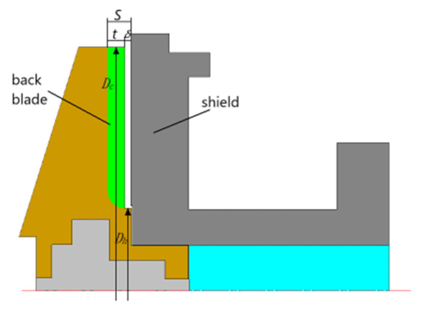
The back blade has a number of radial ribs [23] on the rear cover plate of the impeller, as shown in Figure 1.
Assuming that the gap between the back blade end face and the pump case δ is close to zero, the liquid was an ideal liquid and rotated at a speed of . The pressure resistance of the back blade seal was the centrifugal pressure generated by the back blade:
where ΔP is the pressure resistance of the back blade seal; is the angular velocity of the impeller; g is the acceleration of gravity; Dc was the outer diameter of the back blade; and Dh is the inner diameter of the back blade.
In practical applications, δ was not zero and the liquid in the cavity was viscous, and the angular velocity of the liquid was: . Therefore, the actual pressure resistance of the back blade was:
where K is the leaf coefficient. Due to the complexity of the influencing factors of the value of K, existing studies established the corresponding empirical formula or measured curve to determine the value of K through the measured method, and this paper adopted the empirical formula proposed by A. JStcpanoff [24]:
where S is the distance between the impeller cover plate and the pump case, ; and t is the height of the back leaf.
By substituting Equations (1) and (3) into Equation (2), the actual pressure resistance of the back blade seal could be obtained.
It can be seen from the above equation that the actual pressure resistance of the back blade seal was determined by the angular velocity , the gap between the end face of the back blade and the pump case δ, the height of the back blade t, the outer diameter of the back blade Dc, and the inner diameter of the back blade Dh.
2.1.2. Theory Pressure Resistance of the Magnetic Fluid Seal
The magnetic fluid seal was realized by using the response characteristics of the magnetic fluid to the magnetic field [8], which was composed of a permanent magnet, pole shoes, a magnetic fluid and a shaft, etc. Its structure was shown in Figure 2. The surfaces of the pole shoes or the shaft were distributed with several teeth, and the magnetic field strength at the tooth tip was strong. Under the action of magnetic field force, several “O”-shaped magnet fluid rings were formed at the seal gap of the tooth tip position to achieve multi-stage sealing and to resist the pressure difference.
The pressure resistance of magnetic fluid seals for sealing gases was:
where N is the sealing stage; Ms is the saturation magnetization strength of the magnetic fluid; Bimax and Bimin were the maximum and minimum magnetic flux density at the ith pole tooth in the sealing gap, respectively.
Since the shaft speed had a great influence on the pressure resistance of the magnetic fluid for the sealing liquid, Wang [25] corrected the pressure resistance formula of the magnetic fluid for sealing liquids:
where , the pressure resistance of the magnetic fluid seal decreased with the increase in the shaft speed.
2.2. Failure Mechanism of the Magnetic Fluid Seal for Sealing Liquids
When the magnetic fluid was used for dynamic sealing fluids, the two fluids erode each other at their interface during the sealing process due to the difference in flow field gradients. The internal friction of the fluid would gradually wash away the magnetic fluid by the sealing the medium under the shear stress, and the shape of the interface between the two fluids would be changed by the viscous force of the fluid parts. At higher speeds, Kelvin–Helmholtz (K-H) interfacial instability occurred between the magnetic fluid and the sealing medium. Some researchers have pointed out that K-H interfacial instability is the main reason why magnetic fluids rapidly failed to seal a liquid medium at high speeds [26]. The magnetic field stabilized the interface between the magnetic fluid and the other liquid medium parallel to it, and Rosensweig considered this effect and proposed a criterion for the Kelvin–Helmholtz interface instability between magnetic fluid and non-magnetic fluid:
where the subscription a represents a non-magnetic fluid, and the subscription b represents a magnetic fluid. and are the rates of motion of the two fluids. and represent the density of the two fluids, and are the relative permeability of the two fluids and is the component of the magnetic field strength parallel to the interface.
The pressure resistance and seal life were two important indexes of magnetic fluid sealing performance which were measured by different experimental methods. The pressure resistance was measured under the condition of a continuous increase in sealing pressure, until the magnetic fluid film broke. The instantaneous breakage process of the magnetic fluid film is shown in Figure 3.
As the pressure on one side of the liquid medium increased, the magnetic fluid moves to the weaker side of the pressure, and the increased volume force due to the change in the interface shape was balanced with the increased pressure. When the external pressure reached the pressure resistance, the volume force of the magnetic fluid reached the maximum under the polar teeth. As the pressure continued to increase, the volume force could not balance with the pressure; then, a passage was created in the sealing film, which led to the failure of the magnetic fluid seal.
The seal life was measured under the fixed pressure below the maximum pressure resistance, which represented the loss process of the magnetic fluid film over a long period of time. The loss process of the magnetic fluid film is shown in Figure 4.
Due to the difference in the stress tensor between the magnetic fluid and the sealed liquid medium at the interface, the magnetic fluid at the interface was gradually washed away. As the total amount of magnetic fluid in the sealing gap decreased, the axial width of the magnetic fluid sealing film decreased, i.e., the magnetic fluid sealing film became thinner. When the sealing film of the magnetic fluid became thinner to a certain extent, the volume force in the magnetic fluid could not balance with the pressure. Channels appeared in the magnetic fluid, which made the seal ineffective.
2.3. Design of the Combined Magnetic Fluid–Back Blade Seal Structure
In order to make the pressure resistance of the back blade seal optimal, the blade coefficient K was set to 0.9112 and the gap between the end face of the back blade and the pump case δ was set to 0.5 mm when the processing requirements were guaranteed [22]. Therefore, the outer diameter of the back leaf Dc was 27 mm, the distance between the back blade seal and the shell was 0.5 mm, the inner diameter of the back leaf Dh was 12 mm, the height of the back leaf was 5 mm, and the number of back leaves was eight. The magnetic fluid seal adopted a six-stage seal and the gap dimension for the magnetic fluid seal was 0.1 mm. The back blade seal of the above parameters was combined with the magnetic fluid seal, and the combined seal structure was designed as shown in Figure 5.
From Equation (4), the theoretical pressure resistance of the above back blade seal structure for sealing water under different shaft speeds could be obtained, as shown in Figure 6.
It can be seen from Figure 4 that the sealing pressure resistance of the back blade gradually increased with the increased in the shaft speed, and the increment in the value of the pressure resistance increased with the increase in the shaft speed.
2.4. Materials
An oil-based magnetic fluid was prepared. Nanometer Fe3O4 was synthesized by the coprecipitation method. The magnetic particle size distribution of Fe3O4 was analyzed by transmission electron microscopy (TEM). The characterization results showed that the Fe3O4 nanoparticles were spherical and monodisperse with an average particle size of 11 nanometers and in narrow distribution, as shown in Figure 7.
The particles coated with surfactant were dispersed in oil and were stirred thoroughly until the two phases were completely mixed. The viscosity of the magnetic fluid in a zero magnetic field environment was 341.4 MPa·s at 40 °C. The magnetization curve of the magnetic fluid selected in this paper is shown in Figure 8.
2.5. Numerical Simulation of Magnetic Field Distribution
Considering that the magnetic fluid seal structure had an axisymmetric structure, the magnetic field simulation model shown in Figure 9 was established.
The simulation of computational fluid dynamics was conducted with Ansys Fluent 15.0. In the simulation, the computational domain was divided by quadrilateral grids. The grids were dense in the area of polar teeth and sparse in the area of air. The smallest mesh was located at the seal gap of the magnetic fluid seal, and its size was 1 × 10⁻⁵ m. The largest grid was located outside the computational domain and was 1 × 10⁻³ m in size.
2.6. Experimental Research
2.6.1. Construction of a Test Bench for the Combined Magnetic Fluid–Back Blade Seal
In order to test the performance of the combined magnetic fluid–back blade seal, an experimental device of a combined seal was built, which was composed of a sealing device, a motor, a speed governor, a gas source, etc. Among them, the sealing device was the combined seal structure of magnetic fluid and back blades designed in this paper, as shown in Figure 10.
2.6.2. Experimental Methods
The pressure resistance experiments and seal life experiments for the magnetic fluid seal and the combined magnetic fluid–back blade seal were carried out, respectively. The experimental procedures were the same for both seal structures. The pressure resistance experiments and the seal life experiments at different speeds needed to be carried out in the following four steps at first:
- (1)
- Install the permanent magnets, pole shoes, and other parts on the shaft, inject 0.7 mL of magnetic fluid into the magnetic fluid sealing gap, and rotate the shaft to evenly distribute the magnetic fluid in the sealing gap;
- (2)
- Mount the sealing assembly on the test bench;
- (3)
- Inject 50 mL of water into the sealing chamber;
- (4)
- Controll the air source and the valve at the upper end of the sealing chamber so that nitrogen slowly enters the sealing cavity.
In the pressure resistance experiments, the pressure value of the sealing chamber at the time of sealing leakage at each speed was recorded as the pressure resistance of the structure for sealing water. The linear velocities corresponding to the shaft speeds in the experiment were 0 m/s (0 rpm), 0.628 m/s (1000 rpm), 1.256 m/s (2000 rpm), 1.884 m/s (3000 rpm), 2.512 m/s (4000 rpm), 3.14 m/s (5000 rpm), and 3.768 m/s (6000 rpm).
In the seal life experiments, the loading pressure reached 80% of the static seal pressure resistance and the pressure was kept unchanged until the seal leaked. Then, the seal life of the structure was recorded. Due to the limitations of the experimental conditions, the experiment was aborted when the seal life reached 120 h.
3. Results and Discussion
3.1. Numerical Simulation of Magnetic Field Distribution
The magnetic flux density at the seal gap was obtained as shown in Figure 11 after dividing the mesh and loading the boundary conditions.
The saturation magnetization strength of the magnetic fluid prepared in this paper was 24.25 kA/m as shown in Figure 5. According to Equation (6), the theoretical pressure resistance of the magnetic fluid seal for the sealing liquid was:
3.2. Experimental Results and Discussion
As shown in Figure 12, with the increase in the shaft speed, the experimental value of the pressure resistance of the magnetic fluid seal gradually decreased from 0.051 MPa to 0.015 MPa, similar to the conclusion of the literature [9,10,11,12,13,14,15,16,17]. The experimental value of the pressure resistance of the combined magnetic fluid–back blade seal first decreased slowly with the increase in the shaft speed, and the pressure resistance reached the minimum value of 0.042 MPa when the shaft speed was 2000 r/min; then, the pressure resistance increased significantly, and when the shaft speed was 6000 r/min, the pressure resistance reached 0.089 MPa, which was nearly one-times higher than the static seal. The experimental values of the pressure resistance of the combined seal at every speed were higher than those of the magnetic fluid seal.
In addition, the pressure resistance of the magnetic fluid seal in the experiment decreased significantly when the speed was within 2000 r/min, and the pressure resistance decreased slowly in other speed ranges. When the shaft speed was in the range of [1000 r/min, 2000 r/min], the decrease in the value of the pressure resistance of the magnetic fluid seal was greater than the increase in the pressure resistance of the back blade seal, so the pressure resistance of the combined magnetic fluid–back blade seal decreased with the increase in the shaft speed. On the contrary, the decrease in the pressure resistance of the magnetic fluid seal in other speed ranges was less than the increase in the pressure resistance in the back blade seal, so the pressure resistance of the combined seal increased with the increase in the shaft speed. The higher the shaft speed was, the stronger the pressure resistance advantage of the combined seal was.
As shown in Figure 12, the fitting curve of the difference between the pressure resistance of the combined seal and the pressure resistance of the magnetic fluid seal obtained from the pressure resistance test results was close to the theoretical pressure curve of the back blade seal. In addition, the fitting curve of the pressure resistance of the magnetic fluid seal could be obtained from the test results too. The pressure resistance of the combined seal could be predicted by the sum of the fitting formula of the pressure resistance of the magnetic fluid seal and the theoretical pressure resistance of the back blade seal.
The above prediction formula varied with the parameters of the combined seal structure, i.e., the magnetic fluid seal structure and the back blade seal structure.
In the seal life experiments, the seal life of the combined magnetic fluid–back blade seal at different speeds was higher than that of the magnetic fluid seal. When the shaft speed was 1000 r/min, the seal life of the magnetic fluid seal and the combined seal both were less than 20 h; when the shaft speed was above 2000 r/min, the seal life of the magnetic fluid seal reduced to zero because the pressure resistance of the magnetic fluid seal was less than the pressure applied on the side of the sealed liquid; the seal life of the combined seal decreased slightly when the shaft speed was within 2000 r/min, and then increased significantly with the increase in shaft speed, with it reaching more than 120 h after the shaft speed increased to 5000 r/min, as shown in Figure 13.
When using the combined magnetic fluid–back blade seal for sealing liquids, with the increase in the shaft speed, the pressure resistance of the back blade seal increased and the growth rate was gradually accelerating; therefore, the pressure applied to the magnetic fluid seal decreased accordingly. When the pressure value was within the pressure resistance range of the magnetic fluid seal, the magnetic fluid seal operated normally and the sealing performance was significantly improved. When the combined seal was stopped or ran at low speed, the magnetic fluid seal played a major role in maintaining the normal operation of the sealing structure. The combined seal could achieve more stable operation at different speeds.
4. Conclusions
A combined magnetic fluid seal and back blade seal structure was designed to seal liquids. The characteristics of positive the correlation between the sealing performance of the back blade and the shaft speed were used to solve the problem of the influence of the shaft speed on the magnetic fluid seal.
The back blade seal in the combined seal played the main role when the shaft speed was high, and the pressure resistance at the shaft speed of 6000 r/min was nearly one-times higher than that of the static seal. The magnetic fluid seal played a major role in the shutdown or low speed state and ensured stable operation under different speeds. A prediction formula of the pressure resistance of the combined magnetic fluid–back blade seal was obtained from the experimental outcomes.
The combined magnetic fluid–back blade seal is an effective method to solve the problem of the magnetic fluid rotary seal for sealing liquids, especially at higher shaft speeds. The higher the shaft speed and the larger the outside diameter of the back blade, the better the performance of the combined seal.
Author Contributions
Methodology, X.H. and Z.L. (Zhenkun Li); Data curation, J.Z., Z.L. (Zhuo Luo) and Y.W.; Writing—original draft, H.W. and Z.G. All authors have read and agreed to the published version of the manuscript.
Funding
This work was financially supported by the Research Project of the China University of Labor Relations, with grant number 23XYJS017; the Second Batch of New Engineering Research and Practice Projects of the Ministry of Education, with grant number E-XTYR20200608.
Institutional Review Board Statement
Not applicable.
Informed Consent Statement
Not applicable.
Data Availability Statement
Not applicable.
Conflicts of Interest
The authors declare no conflict of interest.
References
- Guba, S.; Horváth, B.; Szalai, I. Application and comparison of thermistors and fiber optic temperature sensor reference for ILP measurement of magnetic fluids in double cell magnetic hyperthermia. Heliyon. 2022, 8, 1–7. [Google Scholar] [CrossRef] [PubMed]
- Wang, H. Interface stability of magnetic fluid seal for sealing liquid. J. Phys. Conf. Ser. 2021, 1885, 032008. [Google Scholar] [CrossRef]
- Ym, A.; In, A.; Ty, B. Thermal analysis of a miniature magnetic fluid seal installed in an implantable rotary pump. J. Magn. Magn. Mater. 2022, 548, 168977. [Google Scholar]
- Lange, A.; Gollwitzer, C.; Maretzki, R.; Rehberg, I.; Richter, R. Retarding the growth of the rosensweig instability unveils a new scaling regime. Phys. Rev. E. 2016, 93, 43106. [Google Scholar] [CrossRef] [PubMed] [Green Version]
- Ronald, E.Z.; James, R.M. Dynamics and stability of ferrofluids: Surface interactions. J. Fluid Mech. 1969, 39, 1–24. [Google Scholar]
- Anthony, W.; Melvyn, K.; David, B.L. Studies of the double surfactant layer stabilization of water-based magnetic fluids. J. Colloid Interface Sci. 1991, 144, 236–242. [Google Scholar]
- Qian, J.; Yang, Z. Study of interfacial stability between liquids in magnetic liquid seal. Lubr. Eng. 2008, 33, 14–16. [Google Scholar]
- Rosensweig, R.E. Magnetic fluids. Annu. Rev. Fluid Mech. 1987, 19, 437–463. [Google Scholar] [CrossRef]
- Williams, R.A.; Malsky, H. Some experiences using a ferrofluid seal against a liquid. IEEE Trans. Magn. 1980, 16, 379–381. [Google Scholar] [CrossRef]
- Kurfess, J.; Muller, H.K. Sealing liquids with magnetic liquids some experiences using a ferrofluid seal against a liquid. J. Magn. Magn. Mater. 1990, 85, 246–252. [Google Scholar] [CrossRef]
- Lutest, M.O. Experimental studies of high speed cryogenic magnetic fluid seals. IEEE Trans. MAG 1980, 16, 243–246. [Google Scholar] [CrossRef]
- Etsion, I.; Zimmels, Y. A new hybrid magnetic fluid seal for liquids. Lubr. Eng. 1986, 42, 170–173. [Google Scholar]
- Pinkus, O. Model testing of magnetic fluid seals. ASLE Trans. 1982, 25, 79–81. [Google Scholar] [CrossRef]
- Szydło, Z.S. Investigation of dynamic magnetic fluid seal wear process in utility water environment. Key Eng. Mater. 2011, 490, 143–155. [Google Scholar]
- Mitamura, Y.; Yano, T.; Nakamura, W.; Okamoto, E. A magnetic fluid seal for rotary blood pumps: Behaviors of magnetic fluids in a magnetic fluid seal. Bio-Med. Mater. Eng. 2013, 23, 63–68. [Google Scholar] [CrossRef]
- Mitamura, Y.; Arioka, S.; Sakota, D. Application of a magnetic fluid seal to rotary blood pumps. J. Phys. Condens. Matt. 2008, 20, 1–5. [Google Scholar] [CrossRef]
- Mitamura, Y.; Takahashi, S.; Amari, S. A magnetic fluid seal for rotary blood pumps: Effects of seal structure on long-term performance in liquid. J. Artif. Organs 2011, 14, 23–30. [Google Scholar] [CrossRef]
- Wang, H.; Li, D.; He, H.; Li, Z. Performance of the ferrofluid seal with gas isolation device for sealing liquids. Int. J. Appl. Electromagn. Mech. 2018, 57, 107–122. [Google Scholar] [CrossRef]
- Szczech, M. Experimental study on the leak mechanism of the ferrofluid seal in a water environment. IEEE Trans. Magn. 2021, 57, 4600510. [Google Scholar] [CrossRef]
- Li, X.; Li, Z.; Zhu, B.; Cheng, J.; Li, W.; Yuan, J. Optimal design of large gap magnetic fluid sealing device in a liquid environment. J. Magn. Magn. Mater. 2021, 540, 1–11. [Google Scholar] [CrossRef]
- Guo, M.; Chen, Z.; Choi, Y.D. Design and cfd analysis of screw centrifugal pump model. J. Korean Soc. Mar. Eng. 2019, 43, 640–647. [Google Scholar] [CrossRef]
- Cai, X.; Zhou, S.P. Study on the influence of back blade shape on the wear characteristics of centrifugal slurry pump. Mater. Sci. Eng. 2016, 129, 012058. [Google Scholar] [CrossRef] [Green Version]
- Sarah, B.; Jacky, F.; Xavier, B.; Yannick, D. Experimental investigation of the blade seal interaction. J. Eng. Tribol. 2013, 229, 980–995. [Google Scholar]
- Tarzia, V.; Bortolussi, G.; Penzo, V.; Bejko, J.; Gallo, M.; Bianco, R.; Bottio, T.; Gerosa, G. Hemocompatibility of axial versus centrifugal pump technology in mechanical circulatory support devices. Artif. Organs. 2015, 39, 723–729. [Google Scholar]
- Wang, H. Theoretical and Experimental Study on Magnetic Fluid Rotary Seal for Sealing Liquid; China Textile & Apparel Press: Beijing, China, 2021. [Google Scholar]
- Li, Z.; Li, D.; Chen, Y.; Yang, Y.; Yao, J. Influence of viscosity and magnetoviscous effect on the performance of a magnetic fluid seal in a water environment. Tribol. Trans. 2018, 61, 367–375. [Google Scholar] [CrossRef]
Figure 1.
Structure diagram of the back blade seal.

Figure 2.
Schematic diagram of the magnetic fluid seal structure.

Figure 3.
The instantaneous breakage process of the magnetic fluid film.

Figure 4.
The process of wastage of the magnetic fluid film during a long period.

Figure 5.
Schematic diagram of the combined magnetic fluid seal and back seal: 1—shaft, 2—bearing, 3—magnetic isolation ring, 4—permanent magnet, 5—O-shaped rubber rings, 6—pole pieces, 7water-stop sheet, 8—back blade seal, and 9—shell.
Figure 5.
Schematic diagram of the combined magnetic fluid seal and back seal: 1—shaft, 2—bearing, 3—magnetic isolation ring, 4—permanent magnet, 5—O-shaped rubber rings, 6—pole pieces, 7water-stop sheet, 8—back blade seal, and 9—shell.

Figure 6.
Theoretical critical pressure of the back blade seal.

Figure 7.
TEM images of the Fe3O4 particles.

Figure 8.
The magnetization curve of the magnetic fluid.

Figure 9.
Simulation model of the magnetic field of the magnetic fluid seal.

Figure 10.
The sealing device in the experiment: 1—pole pieces, 2—permanent magnet, 3—back blade seal, 4—water-stop sheet, 5—bearing, 6—magnetic isolation ring, 7—shaft, 8—sealing chamber, and 9—shell.
Figure 10.
The sealing device in the experiment: 1—pole pieces, 2—permanent magnet, 3—back blade seal, 4—water-stop sheet, 5—bearing, 6—magnetic isolation ring, 7—shaft, 8—sealing chamber, and 9—shell.

Figure 11.
The distribution of the magnetic flux density in the sealing gap.

Figure 12.
Pressure resistance at different shaft speeds.

Figure 13.
Seal life at different shaft speeds.

Disclaimer/Publisher’s Note: The statements, opinions and data contained in all publications are solely those of the individual author(s) and contributor(s) and not of MDPI and/or the editor(s). MDPI and/or the editor(s) disclaim responsibility for any injury to people or property resulting from any ideas, methods, instructions or products referred to in the content. |
© 2023 by the authors. Licensee MDPI, Basel, Switzerland. This article is an open access article distributed under the terms and conditions of the Creative Commons Attribution (CC BY) license (https://creativecommons.org/licenses/by/4.0/).
Share and Cite
MDPI and ACS Style
Wang, H.; Gao, Z.; He, X.; Li, Z.; Zhao, J.; Luo, Z.; Wei, Y. Performance of Magnetic Fluid and Back Blade Combined Seal for Sealing Water. Magnetochemistry 2023, 9, 38. https://doi.org/10.3390/magnetochemistry9020038
AMA Style
Wang H, Gao Z, He X, Li Z, Zhao J, Luo Z, Wei Y. Performance of Magnetic Fluid and Back Blade Combined Seal for Sealing Water. Magnetochemistry. 2023; 9(2):38. https://doi.org/10.3390/magnetochemistry9020038
Chicago/Turabian StyleWang, Hujun, Zhongquan Gao, Xinzhi He, Zhenkun Li, Jinqiu Zhao, Zhuo Luo, and Yaqun Wei. 2023. "Performance of Magnetic Fluid and Back Blade Combined Seal for Sealing Water" Magnetochemistry 9, no. 2: 38. https://doi.org/10.3390/magnetochemistry9020038
Note that from the first issue of 2016, this journal uses article numbers instead of page numbers. See further details here.