
New Type of Alkaline Rechargeable Battery—Ni-Ni Battery


1
BASF/Battery Materials-Ovonic, 2983 Waterview Drive, Rochester Hills, MI 48309, USA
2
Department of Chemical Engineering and Materials Science, Wayne State University, Detroit, MI 48202, USA
3
Material Measurement Laboratory, National Institute of Standards and Technology, Gaithersburg, MD 20899, USA
*
Author to whom correspondence should be addressed.
Batteries 2016, 2(2), 16; https://doi.org/10.3390/batteries2020016
Submission received: 19 April 2016
/
Revised: 26 May 2016
/
Accepted: 1 June 2016
/
Published: 8 June 2016
(This article belongs to the Special Issue Nickel Metal Hydride Batteries)
Abstract
:The feasibility of utilizing disordered Ni-based metal hydroxide, as both the anode and the cathode materials, in alkaline rechargeable batteries was validated for the first time. Co and Mn were introduced into the hexagonal Ni(OH)2 crystal structure to create disorder and defects that resulted in a conductivity increase. The highest discharge capacity of 55.6 mAh·g−1 was obtained using a commercial Li-ion cathode precursor, specifically NCM111 hydroxide, as anode material in the Ni-Ni battery. Charge/discharge curves, cyclic voltammetry (CV), X-ray diffraction (XRD) analysis, scanning electron microscopy (SEM), transmission electron microscopy (TEM), X-ray energy dispersive spectroscopy (EDS) analysis, and electron energy loss spectroscopy (EELS) were used to study the capacity degradation mechanism, and the segregation of Ni, Co, and Mn hydroxides in the mixed hydroxide. Further optimization of composition and control in micro-segregation are needed to increase the discharge capacity closer to the theoretical value, 578 mAh·g−1.

1. Introduction
The first Ni(OH)2-based alkaline rechargeable batteries, Ni-Fe and Ni-Cd, were patented by Thomas A. Edison in 1901 and 1902, respectively [1,2]. Since then, many works have been done to improve the performance of rechargeable batteries [3,4,5]. The half-cell reactions at positive and negative electrodes and the full cell reaction are shown in Equations (1)–(3), respectively (where Mt is a transition metal, for example Fe or Cd).
Ni(OH)2 + OH− ⇆ NiOOH + H2O + e− (forward: charge, reverse: discharge)
Mt(OH)2 + 2e− ⇆ Mt + 2OH− (forward: charge, reverse: discharge)
Mt(OH)2 + 2Ni(OH)2 ⇆ Mt + 2NiOOH + 2H2O (forward: charge, reverse: discharge)
Basically, the negative electrode uses the transformation of a transition metal between the +2 and 0 oxidation states during charge/discharge operation. During the last two decades, the Ni-TM (transition metal) batteries extended into Ni-Zn and Ni-Co systems. More recently, even a Ni-Mn rechargeable system has been proposed [6]. The comparisons between various Ni-TMs have been summarized in Table 1. The common features of these rechargeable batteries are low-cost and wide working temperature ranges. Although the reaction in Equation (2) involves a two-electron transfer (resulting in a very high theoretical capacity, see Table 2), the utilization of active material is not sufficient. As a result, practical Ni-TM cells often occur with low gravimetric energy and, thus, are not suitable for mobile and automobile applications. In the late 1980s, a new type of alkaline rechargeable battery, nickel/metal hydride (Ni/MH), which uses a metal hydride (MH) alloy as the negative electrode (anode) active material [7] was commercialized by Matsushita, Sanyo, Toshiba, Yuasa, and Ovonic [8]. The new anode half-cell reaction and full-cell reactions are shown in Equations (4) and (5), respectively, where Mh is one of the MH alloys.
Mh + H2O + e− ⇆ MhH + OH− (forward: charge, reverse: discharge)
Mh + Ni(OH)2 ⇆ MhH + NiOOH (forward: charge, reverse: discharge)
With the higher capacity found in the MH alloy (330 mAh·g−1 and 400 mAh·g−1 for AB5 and AB2 MH alloys, respectively), Ni/MH soon controlled the consumer market and was used to power the first commercially built electric vehicle (EV-1) of modern times by General Motors [17]. The history of battery for electrical vehicles, the EV-1 and its immediate predecessors and successors were reviewed by Matthé and Eberle [18]. Later on, Li-ion batteries entered the consumer market and dominated it with a higher energy density compared to that in Ni/MH battery. However, Ni/MH batteries still power more than 10 million hybrid electric vehicles (mainly the Prius, made by Toyota [19]), due to its high power, longevity, and excellent abuse tolerance. With the focus on rechargeable batteries in the consumer market switching to a stationary market, the battery industry is facing two major challenges, specifically cost and cycle stability, in replacing the currently used lead-acid battery [20,21]. The Ni-TM system happens to fall in the right direction for the stationary market. Additionally, by comparing the half-cell reactions in Equations (2) and (4), the Ni-TM batteries demonstrate an advantage over Ni/MH batteries at very low temperatures by not diluting the electrolyte with water generated from the discharge process. A few anode material candidates for the Ni-TM system are compared in Table 2. Although the theoretical capacities obtained from these materials are very high (due to two-electron transfer), the utilization is limited by the poor conductivity of the hydroxide. The electrochemical reaction, Equation (2), can be re-written into a standard form as Equation (6), with the equilibrium potential given by Equation (7) [15]:
HMtO2− + 3H+ + 2e− ⇆ Mt + 2H2O
Eo = Eo(Mt) − 0.00886pH + 0.0295log (HMtO3−)
Lower Eo values correspond to metals with lower oxidation energy (easier to be oxidized). From this table, it is easy to see that both Ni and Co have a potential similar to Cd and can have highly reversibility redox reactions occur in the voltage range of interest. Significant research has been devoted into Ni-Co batteries and results have been summarized in a review article [22]. In the past, a few methodologies were developed to improve the utilization (reversibility of Equation (2)), including: Reducing crystallite size [22], alloying with B [23], Si [24], P [25], and S [26] to increase the degree of disorder (DOD [27]), mixing silica [28], nitride [29], carbon nanotube [30], and CMK-3 (an ordered mesoporous form of carbon) [31], and forming Co3O4 nanowires [32].
Ni, with a similar oxidation potential and metal–oxygen (M–O) bond strength (Table 2) but a much lower raw material cost compared to Co, is a rational choice for a Ni-TM rechargeable system. The challenge is the same as Co(OH)2: Ni(OH)2 has a very poor electronic conductance. Intrinsic pure Ni(OH)2 is a good insulator. In order to increase the conductivity, both composition [33,34,35] and structural [36] modifications are necessary and have been successfully developed. It is interesting to see the use of the disordered Ni(OH)2 as the anode material for the Ni-Ni alkaline battery. With the funding from a U.S. Department of Energy sponsored Robust Affordable Next Generation EV (RANGE) program [37], we are able to investigate the feasibility of such a Ni-Ni battery and present the results in this paper.
2. Experimental Setup
The anode materials were prepared by a co-precipitation method in a continuous stirring tank reactor (CSTR) [7,38], where the sulfate salts of the nickel and/or manganese and cobalt were dissolved in deionized water. A suitable amount of solution was gradually pumped into the reactor in accordance with the desired mole ratio between the three elements. The pH value of the mixture was maintained between 10.5 and 12 by pumping sodium hydroxide solution (30 wt %) at a specific flow rate. Stirring rate (800 rpm), reaction temperature (60 °C), pH value, salt concentration, and residence time are well controlled and experimentally varied to achieve a desirable particle size and morphology.
Carbon black and polyvinylidene fluoride (PVDF) were used in the negative electrode to enhance conductivity and electrode integrity. To construct the negative electrode, 100 mg of active material (hydroxide from one, two, or three transition metals) were stir-mixed thoroughly with carbon black and PVDF in a weight ratio of 3:2:1. A 0.5 × 0.5 inch2 nickel mesh was used as a substrate and current collector with a nickel mesh tab leading out of the square substrate for testing connections. The mixture of carbon black, PVDF, and metal hydroxides was evenly pressed onto both sides of the nickel mesh by a hydraulic press under 300 MPa for 5 s to form the anode for this experiment. The positive electrode was a sintered type of Ni0.9Co0.1 active material, which is commonly used in Ni-Cd batteries. The positive and negative electrodes were sandwiched together with a polypropylene/polyethylene separator in a flooded half-cell configuration. The capacity at the positive electrode was significantly more than that at the negative electrode, resulting in a negative limited design. Electrochemical testing was performed with an Arbin electrochemical testing station (Arbin Instrument, College Station, TX, USA). Cyclic voltammetry (CV) was obtained using a Gamry Potentiostats (Gamry Instruments Inc., Warminster, PA, USA). The particle size distribution of the powder was measured with a Microtrac-SRA 150 (Microtrac, Montgomeryville, PA, USA). X-ray diffraction (XRD) analysis was performed with a Philips X’Pert Pro X-ray diffractometer (Philips, Amsterdam, The Netherlands) and the generated patterns were fitted, and peaks indexed, by Jade 9 software (Jade Software Corp. Ltd., Christchurch, New Zealand). A JEOL-JSM6320F scanning electron microscope (SEM, JEOL, Tokyo, Japan) with energy dispersive spectroscopy (EDS) was applied in investigating the phase distributions and compositions of the powders. A FEI Titan 80–300 (scanning) transmission electron microscope (TEM/STEM, Hillsboro, OR, USA) was employed to study the microstructure of the alloy samples. For TEM characterization, mechanical polishing was used to thin samples, followed by ion milling.
3. Results
3.1. Electrochemical Measurements
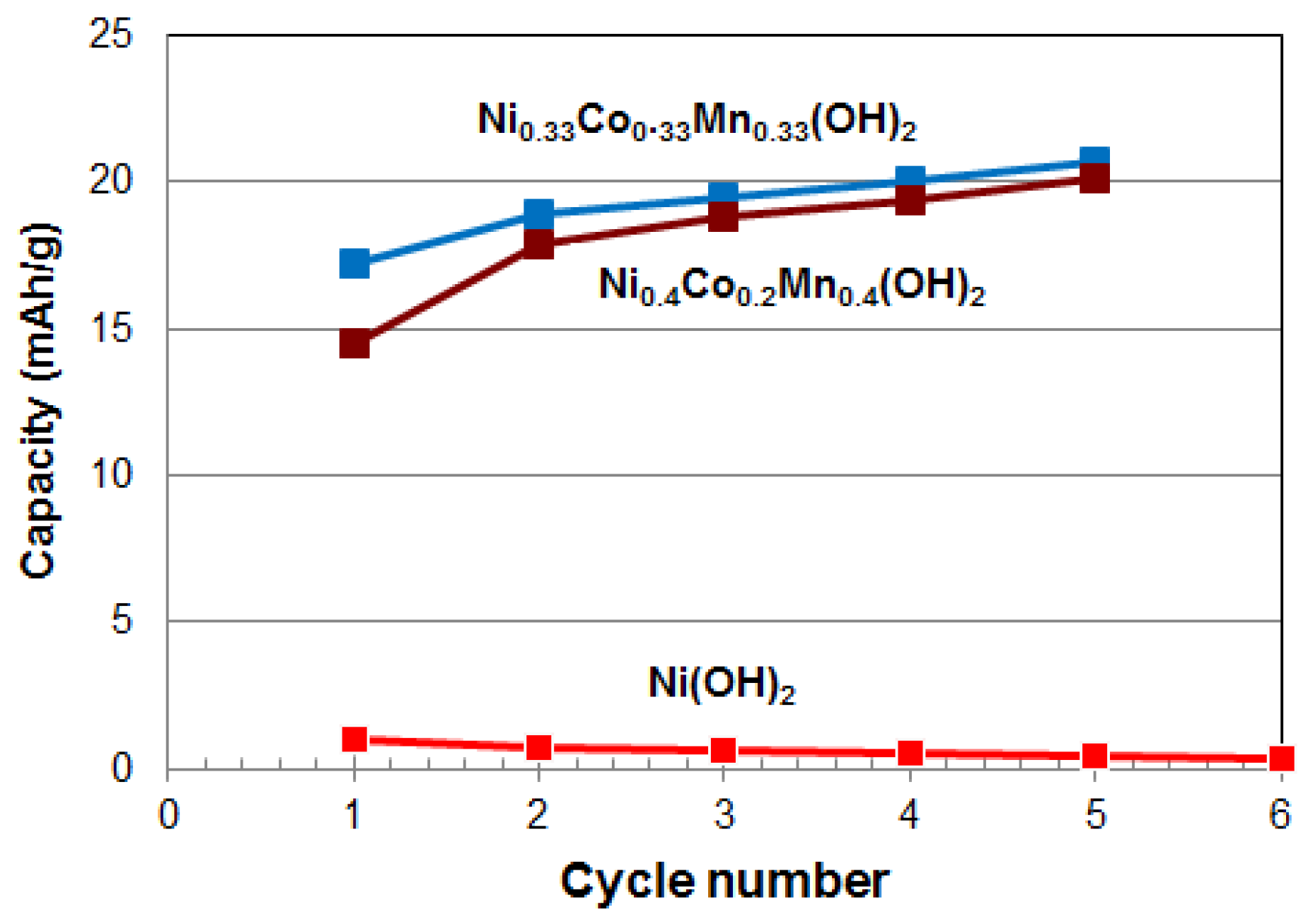
Seven hydroxides, two elements (Ni and Mn), three binaries (Ni-Co, Ni-Zn, and Ni-Mn), and two ternaries (both based on Ni-Co-Mn) were prepared by the CSTR process. The ternary hydroxides are the precursor material for the cathode materials used in Li-ion rechargeable batteries, and herein is used as an anode material for a Ni-Ni battery. Their composition and observed discharge capacities at a discharge current of 5 mA·g−1 from Cycles 1 and 5 are listed in Table 3. All the elemental and binary hydroxides show zero, or close to zero, capacity and both ternary hydroxide, NCM111 hydroxide (Ni0.33Co0.33Mn0.33) and NCM424 hydroxide (Ni0.4Co0.2Mn0.4), show the best capacities at approximately 20 mAh·g−1 (Figure 1). It is interesting to find that the capacity improves with increasingly DOD through addition of more ingredients in the co-precipitation process. In principle, the idea of using a disordered hydroxide during the CSTR process is validated, but composition and process optimizations are necessary for a further improvement in capacity.
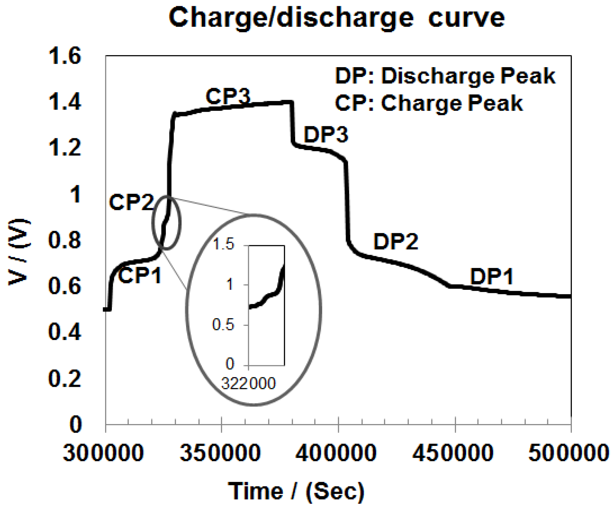
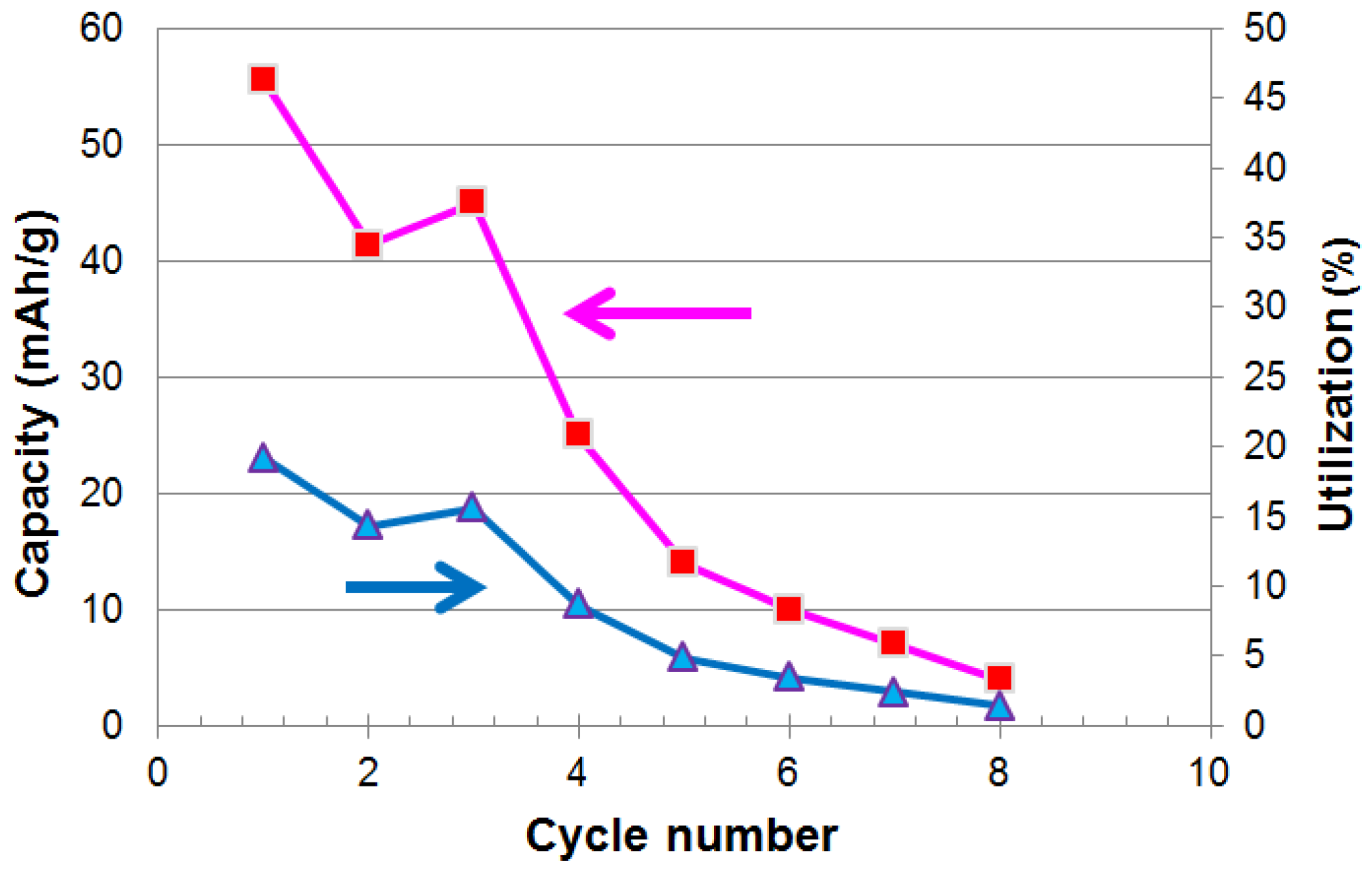
The electrochemical properties of the NCM111 hydroxide were further tested with a charge rate of 5 mA·g−1 and discharge rate of 0.4 mA·g−1. The charge and discharge voltage curves during the first cycle are plotted in Figure 1. The first charge plateau is observed at 0.71 V (versus Ni(OH)2 cathode), corresponding to a discharge plateau at 0.68 V. A second plateau occurs at 1.38 V, with a corresponding discharge plateau at 1.19 V. Discharge voltage efficiency is defined as discharge voltage divided by the charge voltage, which is read at the middle point of the voltage plateau. The first charge reaction has a discharge voltage efficiency of 96%, compared to 86% for the second redox reaction. The highest discharge capacity of the NCM111 hydroxide is 55.6 mAh·g−1 and was observed during the first cycle (Figure 2). Degradations in both capacity and utilization (ratio of charge out versus charge in) with cycling can be easy seen in Figure 3. The cause of these degradations at a relatively low rate will be reported in the following sessions.
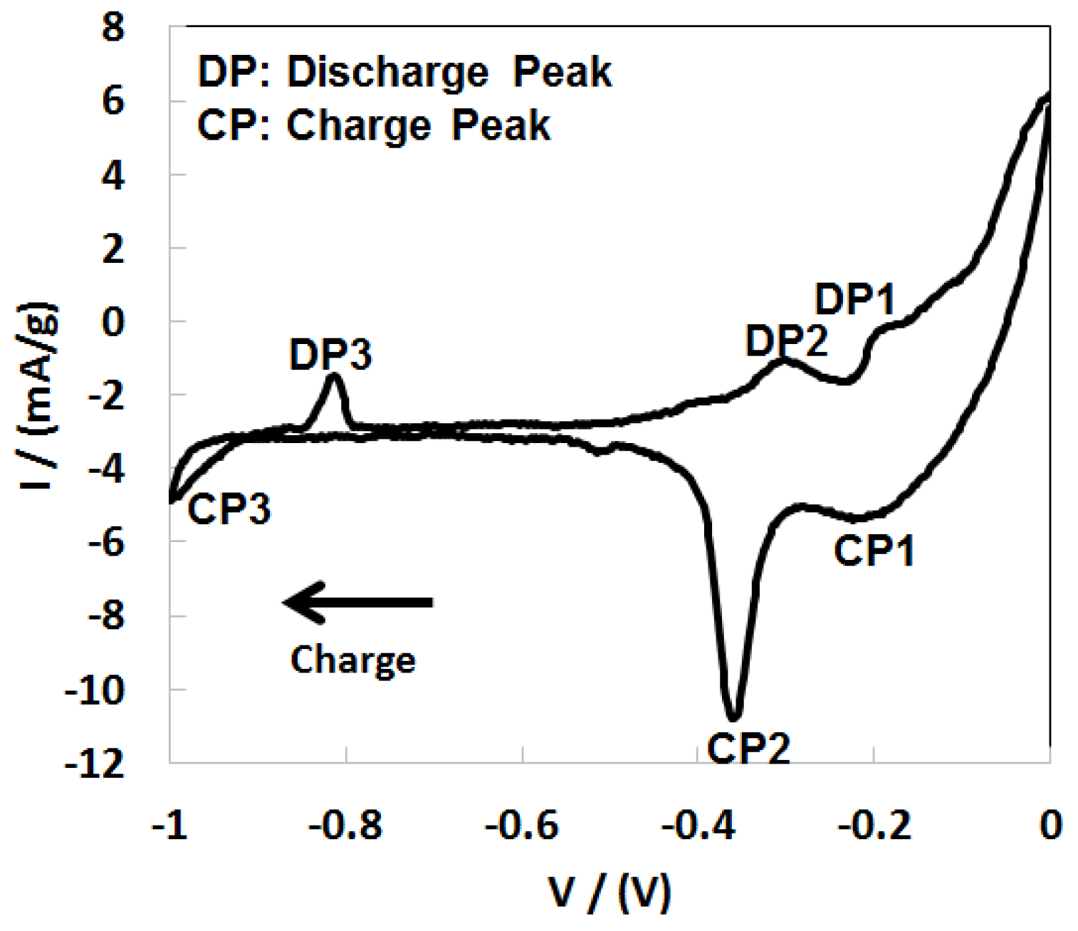
The CV curves of the NCM111 hydroxide anode are plotted in Figure 4. The same cell configuration was used in the CV testing as in the charge/discharge testing, except that an Hg/HgO reference electrode was employed. Corresponding to the charge/discharge plateau at 1.38 V (versus cathode) and 1.19 V (versus cathode) from the charge and discharge curves, two peaks at −1.0 V (versus Hg/HgO) and −0.8 V (versus Hg/HgO) further verified the existence of one of the two redox reactions in Ni-Ni batteries. Similarly, the charge/discharge peaks at −0.37 V (versus Hg/HgO) and −0.2 V (versus Hg/HgO) correspond to the peaks at 0.71 V (versus cathode) and 0.68 V (versus cathode). The additional redox peaks in the CV curve at close to 0.0 V (versus Hg/HgO) is due to the oxidation of water into oxygen in the electrolyte during overcharge. The reduction of the residue oxygen on the surface was lowered during charging, causing a wide peak at −0.21 V (versus Hg/HgO).
3.2. X-ray Diffraction Analysis
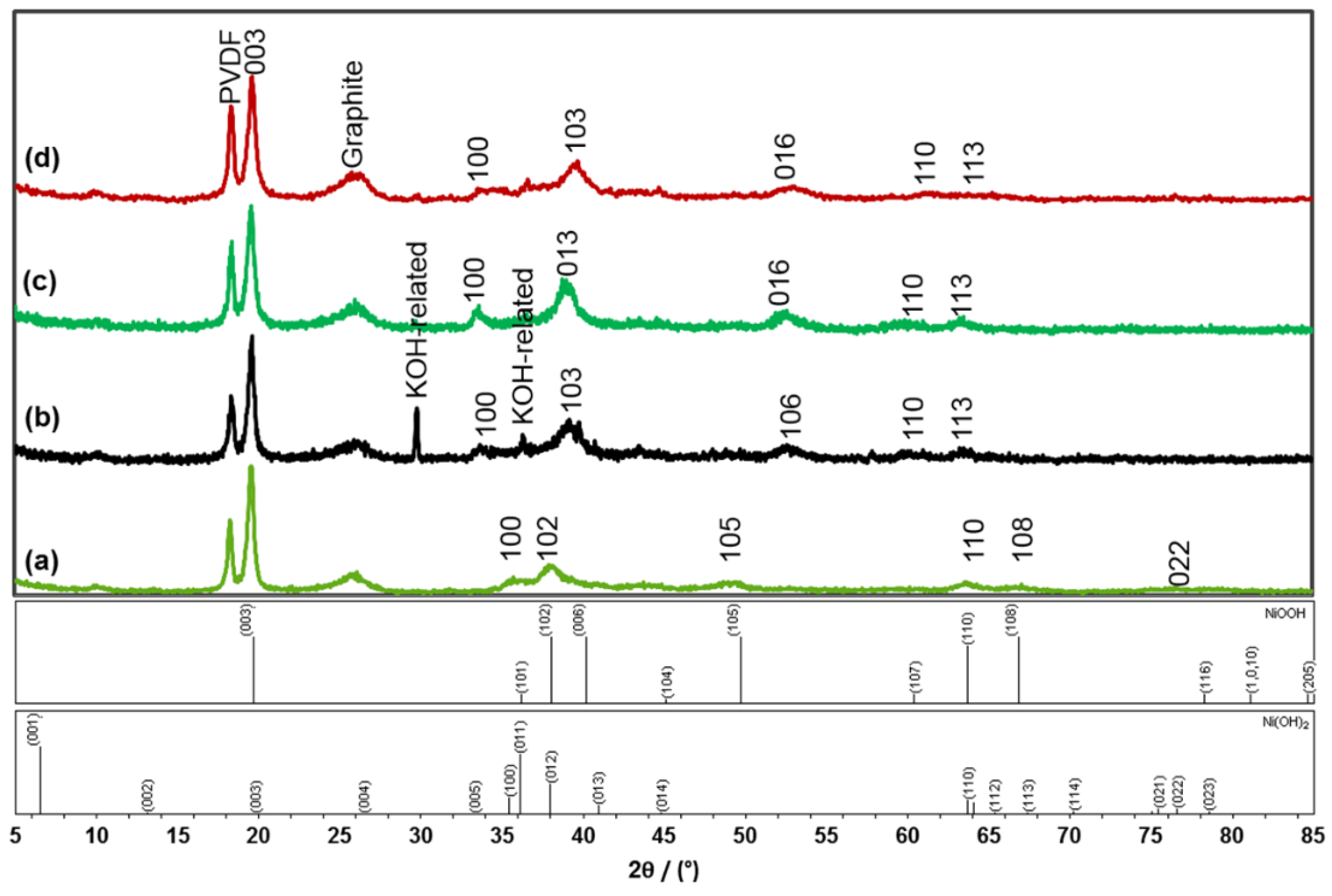
The crystal structure of the NCM111 hydroxide anode at the charged state, the 1st discharge plateau, and the discharged state were characterized by XRD analysis and the resulting patterns are shown in Figure 5. The lattice constants of the hexagonal hydroxide phase were obtained through the curve fitting function offered in Jade 9.0 Software and the results are listed in Table 4. The charge or discharge process of the cell was terminated at the desired discharge state before it was disassembled. The anode samples were soaked in deionized water overnight and rinsed thoroughly to remove any KOH electrolyte residue. The anodes were then completely dried in air under room temperature before XRD analysis. However, some peaks from residue KOH (with a slightly larger lattice constant when comparing to pure KOH, due to some water content) are still present in Figure 5b.
The XRD patterns of the NCM111 hydroxide anode at different discharge state can be fitted with a hexagonal unit cell (as the original Ni(OH)2). Compared to that in the fresh sample (Figure 5a), the (100) peak shows shifts from 35.73° to 33.59° and 33.46° for those in the first plateau (Figure 5b) and charged state (Figure 5c), respectively. Accordingly, the lattice parameter, a, increases from 2.92 Å to 3.09 Å and 3.11 Å, respectively. The lattice parameter, c, fitted by Jade 9, also showed a 2.8% increase, from 13.44 Å to 13.82 Å. The changes in both lattice parameters, a and c, indicate unit cell expansion during the charge process. During the charge phase, Ni was reduced to a lower state and extracted from the NCM111 hydroxide unit cell, leaving Co and Mn with a larger radius supporting the original hexagonal crystal structure. The extraction of small radius Ni from the basal plane may be the reason for the 5.8% increase in lattice parameter a. Comparably, the 2.8% decrease in c might be due to the extraction of a hydroxide group from between the basal planes, which caused partial collapse of this layer. The separation of Ni from the NCM111 hydroxide was also detected by EDS analysis, as demonstrated in the next section.
At a discharged state, the 100 peak shifted back to 33.69° (Figure 5d), corresponding to a decrease in a to 3.02 Å, which is smaller than observed in the charged state and the first plateau, but not fully reverted to the fresh state before cycling. Compared to the decreases in a, the parameter c decreased less during the discharge. The major changes in parameter a and the almost same changes in c indicate that the reaction sites are majorly involved in the basal plane during the charging, causing an expansion in the a–b planes and a slightly expansion in the c direction. During discharge, a and c recovered to 3.02 Å and 13.85 Å, but did not achieve the values seen in the original fresh anode state. The extraction in the c direction was insignificant after the initial charge, so that NCM111 hydroxide can still maintain a hexagonal structure with Co and Mn supporting the basal planes.
3.3. Scanning Electron Microscopy/Energy Dispersive Spectroscopy Characterizations
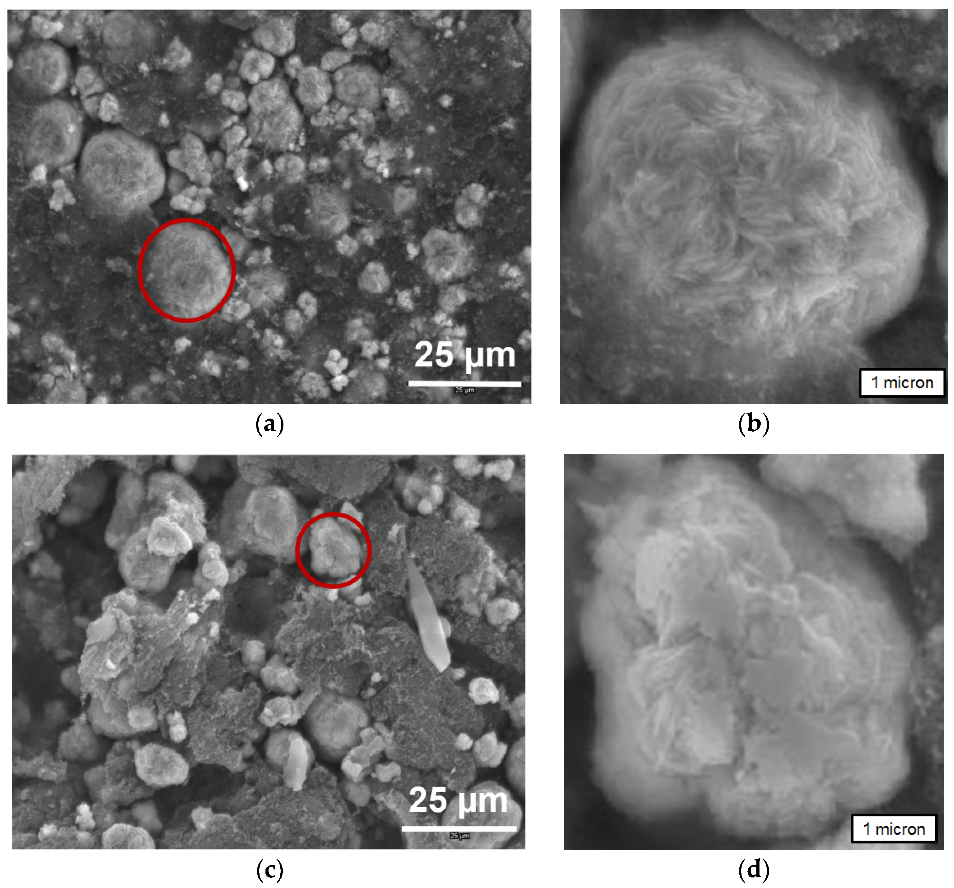
As shown in Figure 6a, the diameter range of pristine NCM111 hydroxide particles varies from several microns to as large as 30 μm. The surface of the NCM111 hydroxide particles is covered by thin flakes vertical to the particle surface and approximately 100 nm thick with diameters around 500 nm. After cycling, the flakes change their orientation from perpendicular to the surface (Figure 6b) to parallel with the surface (Figure 6d), indicating a regrowth of hydroxide during cycling.
The EDS mappings of the NCM hydroxide anode before and after cycling are shown in Figure 7a,b, respectively. The nickel, cobalt, and manganese are distributed evenly in the sample before cycling. However, the nickel distribution of the NCM hydroxide anode after cycling differs from the distribution of cobalt and manganese. The two areas are indicated by red and blue circles that show the differences between Ni and Co/Mn after the cycling. This difference can be explained by the segregation of Ni(OH)2 out of the hexagonal structure of NCM111 hydroxide material during the cycling, as observed in the EDS map. This is in agreement with the XRD pattern, that the lattice constant a increases during the charge process and decreases during discharge, while c less noticeable changes. This segregation of Ni is the main cause for the capacity and utilization degradations discussed in Section 3.1. The Ni segregation is more severe during slower rate discharges and needs to be controlled to sustain the initial capacity. Approaches for such segregation-prevention may include implantation of grain growth inhibitor [40], control of oxygen impurities [41], addition of elements with different solubilities among phases [42], addition of rare earth elements [43], addition of other transition metals with larger ionic radii, introduction of a pulse charge/discharge method to interrupt the formation of Ni(OH)2 isolated grain, surface modification with surfactant to make it more difficult to precipitate into larger Ni(OH)2 grains, a new combination of alkali [44] and salt [45] used in the electrolyte, and improvements in the co-precipitation process to evenly distribute the cation in the hydroxide.
3.4. Transmission Electron Microscopy Characterizations
To locally study the distribution change of Ni, Co, and Mn after cycling, scanning TEM was performed. As shown in Figure 8a, the EDS spectrum was collected from seven evenly distributed spots along the line, with an electron beam spot size of 1 nm. The relative percent of these three elements are plotted in Figure 8b. The plot clearly shows that while the distribution of Co is generally uniform, Ni content is higher in the center of the particle, and Mn content is higher at the surface. Compared to the uniform elemental distribution in fresh samples, such an elemental distribution change should be attributed to micro-segregation that occurs during cycling.
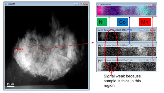
Electron energy loss spectroscopy (EELS) data was also obtained by scanning the indicated region in Figure 9a, which is consistent with EDS analysis results. The phase segregation with cycling in the NCM111 hydroxide sample forms an isolated Ni(OH)2 region which is known to be electrochemically inactive and deteriorates the discharge capacity.
3.5. Discussion
In this work, NCM111 shows the highest degree of compositional disorder and also the highest discharge capacity. However, the high cost of Co prevents the commercialization of this material unless other strong incentives can be obtained. Considering the low voltage of the aqueous system compared to the Li-ion rival using the NCM111 as the cathode, it will be tough for NCM111 Ni-Ni alkaline battery to compete with Li-ion battery unless a capacity close to the theoretical value (ca. 580 mAh·g−1) can be realized. When the Li-industries are moving from NCM111 to NCM424, NCM523, even NCM811 [46,47] to reduce the cost and increase the capacity, such high-Ni precursor is certainly a good candidate for Ni-Ni alkaline battery testing. Other inexpensive transition metals (Cr, Fe, Cu, and Zn) or even non-transition metals (Li, Al, S, and Mg) should also be tested as components to further increase the DOD and cycle stability.
4. Conclusions
A novel ternary NCM111 hydroxide (NiCoMn(OH)6) material was demonstrated for the first time to act as an anode material for alkaline rechargeable batteries. A capacity of 55.6 mAh·g−1 was achieved with a cycle life of 8, without further optimizing. Charge/discharge testing and CV testing verified the existence of a two-step reaction. The chemical reactions have been preliminarily suggested to be two-step reactions within which the Ni(OH)2 is reduced to NiOH at the first plateau and then to Ni at the second plateau. During the cycling, Ni and Ni hydroxide aggregated, while Co and Mn remained at the same location, which led to the loss of disorder in the NCM111 hydroxide structure after cycling, as revealed by XRD, SEM, and TEM analysis. This reduction in DOD is considered to be the major reason of capacity loss over the course of cycling and necessitates immediate attention for future research.
Acknowledgments
This work was financially supported by US DOE ARPA-E under the RANGE program (DE-AR0000386).
Author Contributions
Lixin Wang conceived and performed the experiments, and wrote the paper; Kwo-Hsiung Young helped in data interpretation and paper preparation; Hao-Ting Shen performed the TEM analysis.
Conflicts of Interest
The authors declare no conflict of interest.
Abbreviations
| TM | Transition metal |
| Ni/MH | Nickel/metal hydride |
| MH | Metal hydride |
| EV | Electric vehicle |
| DOD | Degree of disorder |
| M–O | Metal–oxygen |
| RANGE | Robust Affordable Next Generation EV |
| CSTR | Continuous stirring tank reactor |
| rpm | Revolution per minute |
| PVDF | Polyvinylidene fluoride |
| CV | Cyclic voltammetry |
| XRD | X-Ray diffraction |
| SEM | Scanning electron microscopy |
| EDS | X-Ray energy dispersive spectroscopy |
| DP | Discharge peak |
| CP | Charge peak |
| TEM | Transmission electron microscopy |
| Powder diffraction file | |
| EELS | Electron energy loss spectroscope |
References
- Edison, T.A. Reversible Galvanic Battery. U.S. Patent 678,722, 16 July 1901. [Google Scholar]
- Edison, T.A. Reversible Galvanic Battery. U.S. Patent 692,507, 4 February 1902. [Google Scholar]
- Shukla, A.K.; Venugopalan, S.; Hariprakash, B. Nickel-based rechargeable batteries. J. Power Sources 2001, 100, 125–148. [Google Scholar] [CrossRef]
- Morioka, Y.; Narukawa, S.; Itou, T. State-of-the-art of alkaline rechargeable batteries. J. Power Sources 2001, 100, 107–116. [Google Scholar] [CrossRef]
- Tarascon, J.M. Key challenges in future Li-battery research. Philos. Trans. R. Soc. A 2010, 368, 3227–3241. [Google Scholar] [CrossRef] [PubMed]
- Carmichael, C. Making Economical, Green, High-Energy Nickel-Manganese (NiMn) Batteries. Available online: http://www.saers.com/recorder/craig/TurquoiseEnergy/BatteryMaking/BatteryMaking.html (accessed on 1 April 2016).
- Chang, S.; Young, K.; Nei, J.; Fierro, C. Reviews on the U.S. patents regarding nickel/metal hydride batteries. Batteries 2016, 2. [Google Scholar] [CrossRef]
- Ouchi, T.; Young, K.; Moghe, D. Reviews on the Japanese patent applications regarding nickel/metal hydride batteries. Batteries 2016, 2. [Google Scholar] [CrossRef]
- Jiang, W.; Wu, Y.; Cheng, Y.; Wang, L. Industrial application of nickel-iron battery and its recent research progress. Chin. J. Appl. Chem. 2014, 31, 749–756. [Google Scholar]
- Gao, X.P.; Yao, S.M.; Yan, T.Y.; Zhou, Z. Alkaline rechargeable Ni/Co batteries: Cobalt hydroxides as negative electrode materials. Energy Environ. Sci. 2009, 2, 502–505. [Google Scholar] [CrossRef]
- Gao, X.P.; Yang, H.X. Multi-electron reaction materials for high energy density batteries. Energy Environ. Sci. 2010, 3, 174–189. [Google Scholar] [CrossRef]
- PowerGenix Batteries. The Nickel-Zinc Battery. Available online: http://www.powergenix.com/the-nickel-zinc-battery/ (accessed on 6 April 2016).
- Wikipedia Webpage. Nickel-Cadmium Battery. Available online: https://en.wikipedia.org/wiki/Nickel%E2%80%93cadmium_battery/ (accessed on 6 April 2016).
- Lide, D.R. CRC Handbook of Chemistry and Physics, 74th ed.; CRC Press Inc.: Boca Raton, FA, USA, 1993. [Google Scholar]
- Pourbaix, M. Atlas of Electrochemical Equilibrium in Aqueous Solutions; National Association of Corrosion Engineers: Houston, TX, USA, 1974. [Google Scholar]
- Nimmermark, A.; Ohrstrom, L.; Reedijk, J. Metal-ligand bond lengths and strengths: Are they correlated? A detailed CSD analysis. Z. Krist. Cryst. Mater. 2013, 228, 311–317. [Google Scholar] [CrossRef]
- Wikipedia Webpage. General Motors EV1. Available online: https://en.wikipedia.org/wiki/General_Motors_EV1 (accessed on 17 May 2016).
- Matthé, R.; Eberle, U. The Voltec System: Energy Storage and Electric Propulsion. Available online: https://www.selidori.com/tech/scarica.php?id_doc=1090 (accessed on 17 May 2016).
- Tanoue, K.; Yanagihara, H.; Kusumi, H. Hybrid Is A Key Technology for Future Automobiles. In Hydrogen Technology; Léon, A., Ed.; Springer: Berlin, Germany, 2008; pp. 235–272. [Google Scholar]
- Zelinsky, M.; Koch, J.; Fetcenko, M. Heat Tolerant NiMH Batteries for Stationary Power. Available online: https://www.battcon.com/PapersFinal2010/ZelinskyPaper2010Final_12.pdf (accessed on 28 March 2016).
- Zelinsky, M.; Koch, J. Batteries and Heat—A Recipe for Success? Available online: https://www.battcon.com/PapersFinal2013/16-Mike%20Zelinsky%20-%20Batteries%20and%20Heat.pdf (accessed on 28 March 2016).
- Zhao, X.; Ma, L.; Shen, X. Co-based anode materials for alkaline rechargeable Ni/Co batteries: A review. J. Mater. Chem. 2012, 22, 277–285. [Google Scholar] [CrossRef]
- Liu, Y.; Wang, Y.; Xiao, L.; Song, D.; Wang, Y.; Jiao, L.; Yuan, H. Structure and electrochemical behaviors of a series of Co-B alloys. Electrochim. Acta 2008, 53, 2265–2271. [Google Scholar] [CrossRef]
- Wang, Y.; Lee, J.M.; Wang, X. An investigation of the origin of the electrochemical hydrogen storage capacities of the ball-milled Co–Si composites. Int. J. Hydrog. Energy 2010, 35, 1669–1673. [Google Scholar] [CrossRef]
- Cao, Y.; Zhou, W.; Li, X.; Ai, X.; Gao, X.; Yang, H. Electrochemical hydrogen storage behaviors of ultrafine Co-P particles prepared by direct ball-milling method. Electrochim. Acta 2006, 51, 4285–4290. [Google Scholar] [CrossRef]
- Wang, Q.; Jiao, L.; Du, H.; Peng, W.; Liu, S.; Wang, Y.; Yuan, H. Electrochemical hydrogen storage property of Co-S alloy prepared by ball-milling method. Int. J. Hydrog. Energy 2010, 35, 8357–8362. [Google Scholar] [CrossRef]
- Sapru, K.; Reichman, B.; Reger, A.; Ovshinsky, S.R. Rechargeable Battery and Electrode Used Therein. U.S. Patent 4,623,597, 18 November 1986. [Google Scholar]
- Han, Y.; Wang, Y.; Wang, Y.; Jiao, L.; Yuan, H. Characterization of CoB-silica nanochains hydrogen storage composite prepared by in-situ reduction. Int. J. Hydrog. Energy 2010, 35, 8177–8181. [Google Scholar] [CrossRef]
- Yao, S.M.; Xi, K.; Li, G.R.; Gao, X. Preparation and electrochemical properties of Co-Si3N4 nanocomposites. J. Power Sources 2008, 184, 657–662. [Google Scholar] [CrossRef]
- Du, H.; Jiao, L.; Wang, Q.; Peng, W.; Song, D.; Wang, Y.; Yuan, H. Structure and electrochemical properties of ball-milled Co-carbon nanotube composites as negative electrode material of alkaline rechargeable batteries. J. Power Sources 2011, 196, 5751–5755. [Google Scholar] [CrossRef]
- Li, L.; Xu, Y.; An, C.; Wang, Y.; Jiao, L.; Yuan, H. Enhanced electrochemical properties of Co/CMK-3 composite as negative material for alkaline secondary battery. J. Power Sources 2013, 238, 117–122. [Google Scholar] [CrossRef]
- Xu, Y.; Wang, X.; An, C.; Wang, Y.; Jiao, L.; Yuan, H. Effect of the length and surface area on electrochemical performance of cobalt oxide nanowires for alkaline secondary battery application. J. Power Sources 2014, 272, 703–710. [Google Scholar] [CrossRef]
- Fierro, C.; Fetcenko, M.A.; Young, K.; Ovshinsky, S.R.; Sommers, B.; Harrison, C. Nickel Hydroxide Positive Electrode Material Exhibiting Improved Conductivity and Engineered Activation Energy. U.S. Patent 6,228,535, 8 May 2001. [Google Scholar]
- Fierro, C.; Fetcenko, M.A.; Young, K.; Ovshinsky, S.R.; Sommers, B.; Harrison, C. Nickel Hydroxide Positive Electrode Material Exhibiting Improved Conductivity and Engineered Activation Energy. U.S. Patent 6,447,953, 10 September 2002. [Google Scholar]
- Ovshinsky, S.R.; Corrigan, D.; Venkatesan, S.; Young, R.; Fierro, C.; Fetcenko, M.A. Chemically and Compositionally Modified Solid Solution Disordered Multiphase Nickel Hydroxide Positive Electrode for Alkaline Rechargeable Electrochemical Cells. U.S. Patent 5,348,822, 20 September 1994. [Google Scholar]
- Wong, D.F.; Young, K.; Wang, L.; Nei, J.; Ng, K.Y.S. Evolution of stacking faults in substituted nickel hydroxide spherical powders. J. Alloys Compd. 2016. submitted. [Google Scholar]
- Young, K.; Ng, K.Y.S.; Bendersky, L.A. A technical report of the robust affordable next generation energy storage system-BASF program. Batteries 2016, 2. [Google Scholar] [CrossRef]
- Fierro, C.; Zallen, A.; Koch, J.; Fetcenko, M.A. The influence of nickel-hydroxide composition and microstructure on the high-temperature performance of nickel metal hydride batteries. J. Electrochem. Soc. 2006, 153, A492–A496. [Google Scholar] [CrossRef]
- Powder Diffraction File (PDF) Database; International Centre for Diffraction Data: Newtown Square, PA, USA, 2011.
- Siozios, A.; Zoubos, H.; Pliatsikas, N.; Koutsogeorgis, D.C.; Vourlias, G.; Pavlidou, E.; Cranton, W.; Patsalas, P. Growth an annealing strategies to control the microstructure of AlN:Ag nanocomposite films for plasmonic applications. Surf. Coat. Technol. 2014, 255, 28–36. [Google Scholar] [CrossRef]
- Ishijima, Y.; Kannari, S.; Kurishita, H.; Hasegawa, M.; Hiraoka, Y.; Takida, T.; Takebe, K. Processing of fine-grained W materials without detrimental phases and their mechanical properties ta 200–432 K. Mater. Sci. Eng. A 2008, 473, 7–15. [Google Scholar] [CrossRef]
- Wang, M.; Du, J.; Deng, Q.; Tian, Z.; Zhu, J. The effect of phosphorus on the microstructure and mechanical properties of ATI 718Plus alloy. Mater. Sci. Eng. A 2015, 626, 382–389. [Google Scholar] [CrossRef]
- Fu, H.; Xiao, Q.; Li, Y. A study of the microstructures and properties of Fe-V-W-Mo alloy modified by rare earth. Mater. Sci. Eng. A 2005, 395, 281–287. [Google Scholar] [CrossRef]
- Nei, J.; Young, K.; Rotarov, D. Studies in Mg-Ni based metal hydride electrode with electrolytes composed of various hydroxides. Batteries 2016. submitted. [Google Scholar]
- Yan, S.; Young, K.; Ng, K.Y.S. Effects of salt additives to the KOH electrolyte used in Ni/MH batteries. Batteries 2015, 1, 54–73. [Google Scholar] [CrossRef]
- BASF Catalysts. NCM Cathode Materials. Available online: http://www.catalysts.basf.com/p02/USWeb-Internet/catalysts/en/content/microsites/catalysts/prods-inds/batt-mats/NCM (accessed on 17 May 2016).
- Fetcenko, M.A. BASF-ANL Collaboration on NCM Cathode Materials. Available online: http://www.energy.gov/sites/prod/files/2014/11/f19/Fetcenko%20-%20Industry%20Partners%20Panel_0.pdf (accessed on 17 May 2016).
Figure 1.
First cycle charge and discharge curves with a NCM111 hydroxide (Ni0.33Co0.33Mn0.33) negative electrode.
Figure 1.
First cycle charge and discharge curves with a NCM111 hydroxide (Ni0.33Co0.33Mn0.33) negative electrode.

Figure 2.
Discharge capacity obtained from Ni(OH)2, NCM111 hydroxide, and NCM424 hydroxide (Ni0.4Co0.2Mn0.4) negative electrodes with a discharge current of 5 mA·g−1.
Figure 2.
Discharge capacity obtained from Ni(OH)2, NCM111 hydroxide, and NCM424 hydroxide (Ni0.4Co0.2Mn0.4) negative electrodes with a discharge current of 5 mA·g−1.

Figure 3.
Discharge capacity and utilization obtained from a NCM111 hydroxide negative electrode with a discharge current of 0.4 mA·g−1.
Figure 3.
Discharge capacity and utilization obtained from a NCM111 hydroxide negative electrode with a discharge current of 0.4 mA·g−1.

Figure 4.
Cyclic voltammetry (CV) curve for a NCM111 hydroxide negative electrode.

Figure 5.
X-ray diffraction (XRD) patterns of: (a) a pristine NCM111 hydroxide powder; (b) a NCM111 hydroxide electrode at the first voltage plateau; (c) a charged NCM111 hydroxide fresh electrode; and (d) a NCM111 hydroxide electrode at a discharged state. Peak positions of a NiOOH and a Ni(OH)2 structures from Powder Diffraction File (PDF) database [39] 00-006-0075 and 00-059-0462, respectively, are shown in the bottom for comparison.

Figure 6.
Scanning electron microscopy (SEM) micrographs of the NCM111 hydroxide negative material (a,b) before and (c,d) after cycling. Circled areas in (a,c) have been examined at higher magnification, as shown in (b,d).
Figure 6.
Scanning electron microscopy (SEM) micrographs of the NCM111 hydroxide negative material (a,b) before and (c,d) after cycling. Circled areas in (a,c) have been examined at higher magnification, as shown in (b,d).

Figure 7.
Energy dispersive spectroscopy (EDS) mappings of a NCM111 hydroxide anode (a) before and (b) after cycling.
Figure 7.
Energy dispersive spectroscopy (EDS) mappings of a NCM111 hydroxide anode (a) before and (b) after cycling.
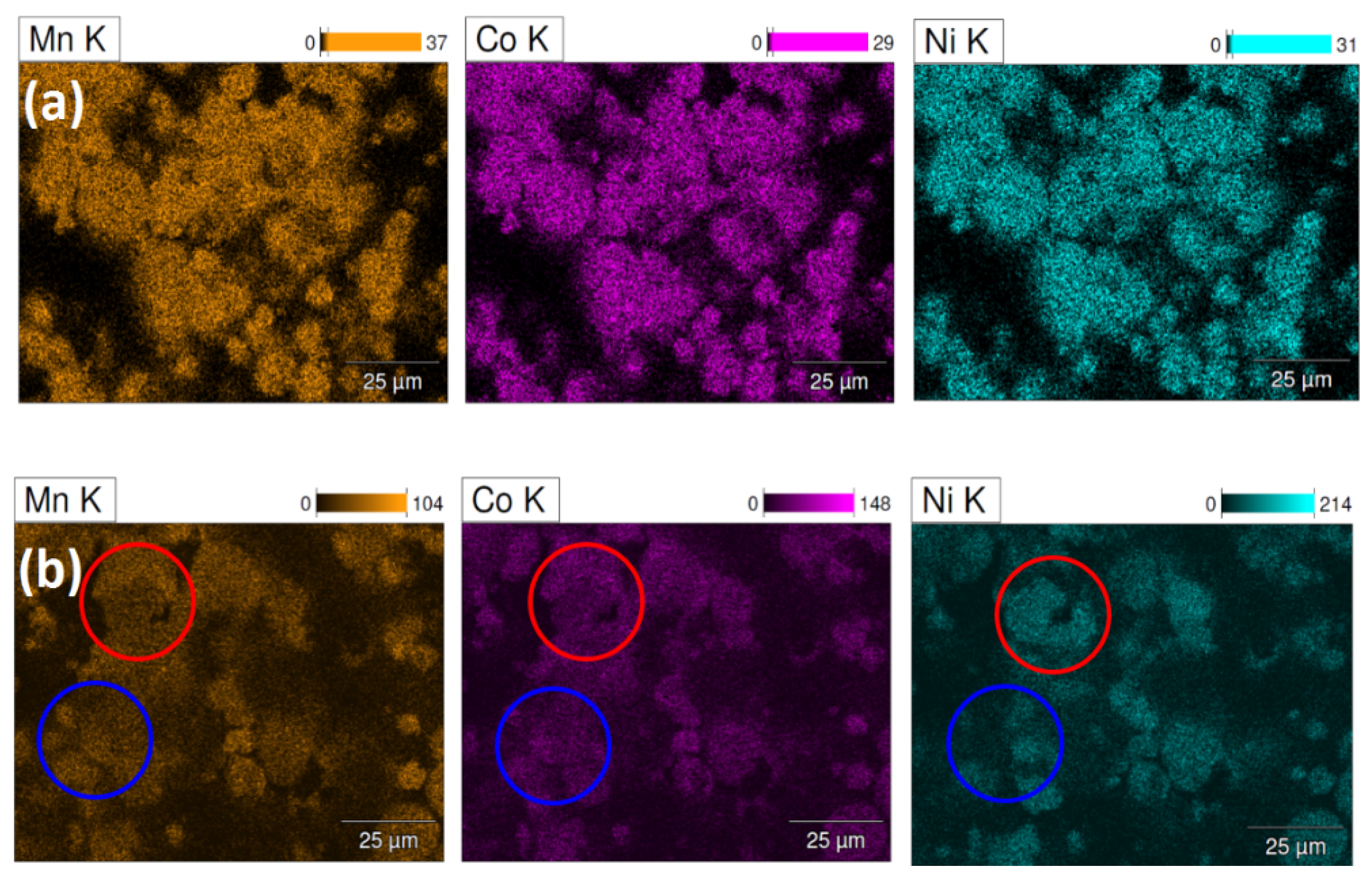
Figure 8.
(a) Transmission electron microscopy (TEM) dark field image of a cross-section of a NCM111 hydroxide after 10 electrochemical cycles and (b) the EDS composition profile of Ni, Co, and Mn along the orange straight line shown in (a).
Figure 8.
(a) Transmission electron microscopy (TEM) dark field image of a cross-section of a NCM111 hydroxide after 10 electrochemical cycles and (b) the EDS composition profile of Ni, Co, and Mn along the orange straight line shown in (a).

Figure 9.
(a) TEM dark field image of a cross-section of a NCM111 hydroxide after 10 electrochemical cycles and (b) electron energy loss spectroscopy (EELS) mappings of Ni, Co, and Ni in the rectangle area highlighted in (a).
Figure 9.
(a) TEM dark field image of a cross-section of a NCM111 hydroxide after 10 electrochemical cycles and (b) electron energy loss spectroscopy (EELS) mappings of Ni, Co, and Ni in the rectangle area highlighted in (a).


| Battery | Anode (Charge/Discharge) | Pros | Cons | Commercial Product | Energy Density |
|---|---|---|---|---|---|
| Ni-Mn | Mn/Mn(OH)2 | • Low cost | Only theoretical | No | 130–190 Wh·kg−1 [6] |
| • High voltage (2.2 V) | |||||
| Ni-Fe | Fe/Fe(OH)2 | • Low cost | • Low energy density | Yes | 30 Wh·kg−1 [9] |
| • Long cycle life | • Low power | ||||
| Ni-Co | Co/Co(OH)2 | • High capacity | High cost | No | Projected to be 165 Wh·kg−1 [10,11] |
| Ni-Zn | Zn/Zn(OH)2 | • Low cost | Cycle life still has room to improve | Yes | 65‒120 Wh·kg−1 [12] |
| • Higher voltage (1.5 V) | |||||
| Ni-Cd | Cd/Cd(OH)2 | • Low cost | Yes | 40‒60 Wh·kg−1 [13] | |
| • Long cycle life | • Toxic | ||||
| • High power at low temperature | • Low energy density |
Table 2.
Properties of hydroxides as negative electrode (anode) candidates in Ni-TM battery systems. All data are from reference [14] unless otherwise cited.
| Hydroxide | Formula Weight | Theoretical Capacity (mAh·g−1) | Density (g·cm−3) | Solubility in Cold Water (g·100·cm−3) | E0(Mt) in Equation (7) [15] (V) | M–O Bond Strength (kJ·mol−1·M) |
|---|---|---|---|---|---|---|
| Mn(OH)2 | 88.94 | 603 | 3.258 | 0.0002 | −0.163 | 402.9 |
| Fe(OH)2 | 89.55 | 597 | 3.4 | 0.00015 | 0.493 | 390.4 |
| Co(OH)2 | 92.93 | 577 | 3.597 | 0.00032 | 0.659 | 384.5 |
| Ni(OH)2 | 92.69 | 578 | 4.15 | 0.013 | 0.648 | 382.0 |
| Zn(OH)2 | 99.39 | 539 | 3.258 | 0.0002 | 0.034 | 180 [16] |
| Cd(OH)2 | 146.41 | 366 | 4.79 | 0.00025 | 0.583 | 235.6 |
| M in M(OH)2 | Ni | Mn | Ni0.91Co0.09 | Ni0.91Zn0.09 | Ni0.91Mn0.09 | Ni0.33Co0.33Mn0.33 | Ni0.4Co0.2Mn0.4 |
|---|---|---|---|---|---|---|---|
| First cycle | 1.0 | 0.0 | 0.0 | 0.0 | 0.0 | 17.2 | 14.5 |
| Fifth cycle | 0.7 | 0.0 | 0.0 | 0.0 | 0.0 | 20.7 | 20.1 |
Table 4.
Lattice constants a and c of hydroxide in NCM111 hydroxide at different stages obtained from the XRD patterns shown in Figure 5.
| Lattice Constant (Å) | Pristine | At the First Discharge Voltage Plateau | After First Charge | After Discharge |
|---|---|---|---|---|
| a | 2.92 | 3.09 | 3.11 | 3.02 |
| c | 13.44 | 13.82 | 13.87 | 13.85 |
© 2016 by the authors; licensee MDPI, Basel, Switzerland. This article is an open access article distributed under the terms and conditions of the Creative Commons Attribution (CC-BY) license (http://creativecommons.org/licenses/by/4.0/).
Share and Cite
MDPI and ACS Style
Wang, L.; Young, K.-H.; Shen, H.-T. New Type of Alkaline Rechargeable Battery—Ni-Ni Battery. Batteries 2016, 2, 16. https://doi.org/10.3390/batteries2020016
AMA Style
Wang L, Young K-H, Shen H-T. New Type of Alkaline Rechargeable Battery—Ni-Ni Battery. Batteries. 2016; 2(2):16. https://doi.org/10.3390/batteries2020016
Chicago/Turabian StyleWang, Lixin, Kwo-Hsiung Young, and Hao-Ting Shen. 2016. "New Type of Alkaline Rechargeable Battery—Ni-Ni Battery" Batteries 2, no. 2: 16. https://doi.org/10.3390/batteries2020016
Note that from the first issue of 2016, this journal uses article numbers instead of page numbers. See further details here.