1. Introduction
Most state-of-the-art cathodes for Li-ion batteries are based on homogeneous Li ion intercalation/deintercalation reactions in lithium-containing transition metal compounds. These cathodes provide good cyclabilities and long cycle life, but limited theoretical capacities. Since nano-sized transition-metal oxide anodes successfully showed large specific capacities based on conversion mechanisms [
1], conversion-type electrode materials have attracted attention not only as anodes, but also as cathodes of Li-ion batteries. The most important advantage of conversion-type materials over insertion compounds is that, theoretically, all of the metal redox potentials of the active material can be utilized during cycling, which indicates a much higher capacity and energy density. Various conversion-type compounds, such as metal oxides [
2,
3,
4], fluorides [
5,
6,
7,
8,
9,
10,
11], sulfides [
12,
13,
14,
15], and nitrides [
16,
17,
18,
19], have been investigated as active materials for Li-ion batteries. Among them, only metal fluorides could be studied as cathode materials due to their relatively high operating potential, which is induced by highly ionic metal-ligand bonds [
20,
21]. From the standpoints of cost and environmental impact, iron fluoride is one of the most promising candidates among the conversion-type cathodes, and has been investigated by many researchers [
5,
6,
7,
8,
20]. Moreover, FeF
3 was reported to show better thermal stability than lithium transition-metal oxide cathodes in associated electrolytes due to the absence of oxygen atoms [
22,
23,
24]. However, metal fluorides have poor electronic conductivity due to their ionic character, with large energy gaps. This results in a disparity between the theoretical and practical capacities, as well as poor cyclability.
Iron oxyfluoride, the subject of this paper, is a reasonable alternative to iron fluorides. Owing to the introduction of more covalent M–O bonds into the highly ionic fluoride structure, iron oxyfluoride is expected to have better electrochemical performance than iron fluorides due to the improved electronic conductivity. Moreover, the theoretical capacity is also increased from 712 mAh g
−1 for FeF
3 to 885 mAh g
−1 for FeOF. Iron oxyfluorides were traditionally synthesized through a solid-state reaction of Fe
2O
3, with FeF
3 in a high-pressure inert atmosphere at 950–1000 °C [
25,
26,
27]. The products were FeO
xF
2−x solid solutions, where x was tunable between two and one. To obtain microcrystalline compounds and simplify the synthesis process, Pereira and co-workers proposed a low-temperature solution process for iron oxyfluoride synthesis [
28]. The synthesized products were used to fabricate a carbon–iron oxyfluoride nanocomposite, which was applied as cathodes in Li-ion batteries and obtained a discharge capacity of 430 mAh g
−1. Also, as a benefit of the introduction of oxygen into the fluoride sublattice, the reversibility of the conversion process were improved. In order to reduce the synthesis time to less than 1 min, our group developed a novel quick synthesis process by using a roll-quenching method [
29]. Such quick synthesis process is useful to reduce the volatilization of fluorine in FeOF, as well as the process cost. Although the roll-quenching method does not include the calcination process, the obtained FeOF had higher crystallinity and purity than the FeOF obtained by ion-exchange and liquid-state reactions. During electrochemical measurement, the FeOF cathode showed an excellent reversible capacity of 550 mAh g
−1 in a voltage range of 1.3–4.0 V, which corresponded to a 1.8Li reaction. Recently, Lin and coworkers developed a thin solid electrolyte (lithium phosphous oxynitride)-coated FeOF electrode, and the capacity retention was increased to 89% at 100 cycles [
30].
In addition to the material cost, safety issues become more serious for the application of Li-ion batteries. In larger-scale batteries, it becomes more difficult to keep the thermal balance between heat generation and heat dissipation in the cell, because the heat generation is directly proportional to the cell volume (~r3), while the heat dissipation is proportional to the cell surface area (~r2). Moreover, battery accident risk is proportional to the square of the capacity, because the battery accident risk can be expressed by the product of the accident probability and the accident damage, and each is proportional to the capacity. Therefore, an investigation of the thermal characteristics of FeOF cathodes is important before their further application for large-scale cells. Especially, fluorine-contained FeOF is naturally suspected to release some toxic gas at elevated temperatures due to its reactions with the electrolyte. Moreover, the study of the thermal properties of FeOF cathodes is also valuable for evaluating the thermal risk of oxygen-containing conversion-type cathode materials. Based on the thermal analysis data, the mechanism of heat generation and the anion’s contribution to the electrode’s thermal stability should be clarified. Such knowledge will be instructive for finding safer conversion-type electrode materials.
In the present study, by changing the cathode/electrolyte ratio, the thermal properties of FeOF cathodes via different conversion reaction depths in a 1 mol dm−3 LiPF6 in 1:1 ethylene carbonate-dimethyl carbonate (EC-DMC) solution were investigated by using a thermogravimetry-differential scanning calorimeter (TG-DSC). Moreover, a thermogravimetry-differential thermal analysis combined with mass spectrometry (TG-DTA/MS) system was employed to monitor the thermal properties and gas evolution from discharged or charged FeOF cathodes. Based on the results, the heat-generation mechanism was discussed. In addition, by comparing the thermal properties of FeOF with those of the FeF3 and LiFePO4 cathodes, the effect of oxygen introduction on the thermal stability of conversion-type cathodes was evaluated.
2. Experimental Setup
FeOF was synthesized according to the method described by Kitajou and coworkers [
29]. The obtained flake-like FeOF was characterized using an X-ray powder diffractometer (50 kV, 300 mA, Cu-Kα, Rigaku TTRIII (Rigaku, Tokyo, Japan) to ensure the purity of the product. The obtained FeOF was ball-milled with acetylene black (AB, Denka Co., Ltd., Tokyo, Japan) and then mixed with polyvinylidene fluoride (PVdF) binder (KF#7305, Kureha Corp, Osaka, Japan) at a weight ratio of 70:25:5. Circular electrodes of a diameter of 15 mm were dried at 120 °C for 12 h in a vacuum oven.
The FeOF cathodes were electrochemically measured using two-electrode cells (R2032). Each cell consisted of a working electrode, a polypropylene separator (Celgard 3501), and a Li foil as a counter electrode. The electrolyte was commercial 1 mol dm−3 LiPF6/EC-DMC (1:1 v/v, Tomiyama Pure Chemical Industries, Ltd., Tokyo, Japan). The electrochemical cycling started from the discharge process. All cells were cycled at a rate of 10 mA g−1 (current density: 0.035 mA cm−2) in a potential window between 0.7 and 4.0 V, with a relaxation period of 60 min at the end of each charge/discharge course at room temperature. To get a lithiated FeOF cathode with a different discharge depth, the discharge procedure of the cell was interrupted at 2.0 V, 1.3 V, and 0.7 V cutoff voltages, respectively. To get a delithiated FeOF cathode, the charge procedure of the cell was interrupted at a 4.0 V cutoff voltage. All potentials reported in this work refer to the Li/Li+ redox couple.
After electrochemical pretreatments, the cells were disassembled in an Ar glove box. The test electrodes were rinsed and soaked in DMC solvent for 4 h, then vacuum dried for 8 h to remove the electrolyte residue. For thermogravimetric mass spectrometric (TG-MS) analysis, a Rigaku 8210H/5050AW (Rigaku, Tokyo, Japan) TG-DTA/MS system was employed. First, 5 mg of sample powder was packed into a stainless steel pan and transferred into a TG chamber located in an Ar glove box. Then, during temperatures ramping up to 700 °C at a rate of 5 °C min−1 under helium flow, the gaseous species released from the sample were monitored by MS. For DSC analysis, the cathode powder was hermetically sealed in a stainless-steel pan together with some amount of electrolyte. The temperature profile from room temperature to 400 °C was obtained with a Rigaku Thermo Plus TG-DSC 8230L system (Rigaku, Tokyo, Japan) at a heating rate of 5 °C min−1. During measurement, the TG signal was monitored simultaneously to confirm that the pan was hermetic.
3. Results and Discussion
Electrochemical cycling was carried out on the FeOF cathode first.
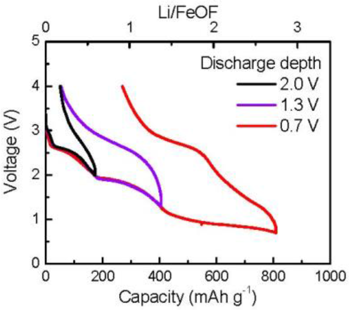
Figure 1 shows the typical charge/discharge cycling profile of the FeOF cathode. To get samples with different cycle depths, different discharge cutoff voltages were set as 2.0, 1.3, and 0.7 V. In the case of narrow discharge conditions down to 2.0 V, the discharge capacity was 174 mAh g
−1, corresponding to a 0.6Li reaction per FeOF. However, it became 406 mAh g
−1 (1.4Li per FeOF) for discharge down to 1.3 V and 812 mAh g
−1 (2.7Li per FeOF) for discharge down to 0.7 V, respectively. According to our previous research, the discharge–charge reaction for FeOF progresses by the following Li insertion and conversion reactions [
29]:
Obviously, the irreversible capacity increased significantly, from about 50 to 270 mAh g−1, in the conversion reaction region, when the cutoff voltage for the discharge procedure dropped from 1.3 to 0.7 V.
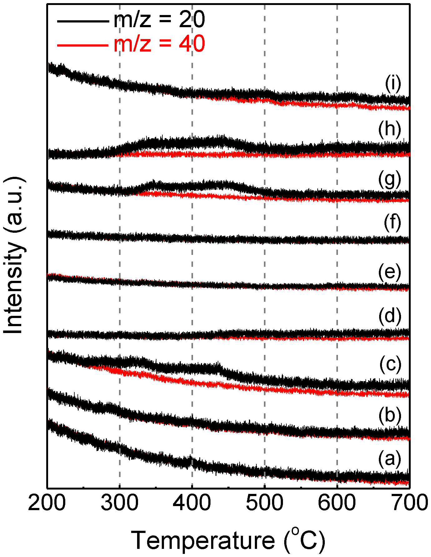
After electrochemical pretreatment, the cathodes were taken out from the cells and prepared for thermal analysis. First, hermetical DSC analyses were carried out on cycled cathode powders, but no significant exo/endothermic signal was obtained with 5 mg samples from room temperature to 500 °C. On the other hand, as a fluorine-contained material, FeOF was expected to release hypertoxic HF gas at elevated temperature. To confirm this, TG-MS analysis of the cathode components and cycled cathodes was carried out from room temperature to 700 °C.
Figure 2 shows the temperature dependence of the MS signal of m/z = 20 obtained with 5 mg sample powder. Because the TG sampling process was performed in an Ar-filled glove box, the m/z = 20 signal included information for both HF
+ and Ar
2+. Therefore, the red MS signal of m/z = 40 (Ar
+) is shown in
Figure 2 to eliminate the attribution of Ar
2+. For the as-synthesized FeOF powder, no HF was detected up to 600 °C, while negligible HF evolution occurred at higher temperature. A similar result was obtained from FeOF powder mixed with acetylene black. However, for the fresh FeOF cathode, a distinct HF release starting at 250 °C was observed, and was attributable to the addition of a 5% PVdF binder. When the fresh cathode was lithiated gradually during electrochemical cycling, the thermal properties of the cathode improved accordingly. With the decrease of the discharge depth from 2.0 V to 0.7 V, the onset temperature of HF evolution increased and the signal intensity decreased, and finally the HF signal vanished. This indicated that more thermally stable fluoride (LiF) were generated in the discharged cathodes during electrochemical cycling [
29]. On the other hand, the charged FeOF cathodes over one electrochemical cycle, which ideally have the same components as the fresh ones, were found to have some different thermal properties according to different cycle depths. The cathodes charged up to 4.0 V after discharge down to 2.0 and 1.3 V showed HF distributions similar to the fresh cathode. However, for the cathode charged up to 4.0 V after discharge down to 0.7 V, its MS spectrum was similar to that of the discharged cathode down to 2.0 V. Obviously, the difference should be attributed to the irreversible Li amount in the FeOF matrix. Reactions between inserted/irreversible Li ions and the PVdF binder were supposed to happen before PVdF thermal decomposition at elevated temperature; as a result, the HF signal coming from PVdF decomposition vanished. This was also one of the reasons for the vanishing of the HF signal in the lithiated cathodes. In summary, it could be concluded that the FeOF cathode had no higher toxic risk than the other fluorine-free electrodes, because the main risk of HF release from the FeOF cathode was from the PVdF binder instead of FeOF itself.
One of the most important thermal characteristics of an electrode material is its thermal behavior in electrolytes. Therefore, DSC analysis of the FeOF cathode with the associated electrolyte was carried out to evaluate the thermal stability of the FeOF cathode in cells. For reference, the initial FeOF cathode before electrochemical cycling was analyzed first.
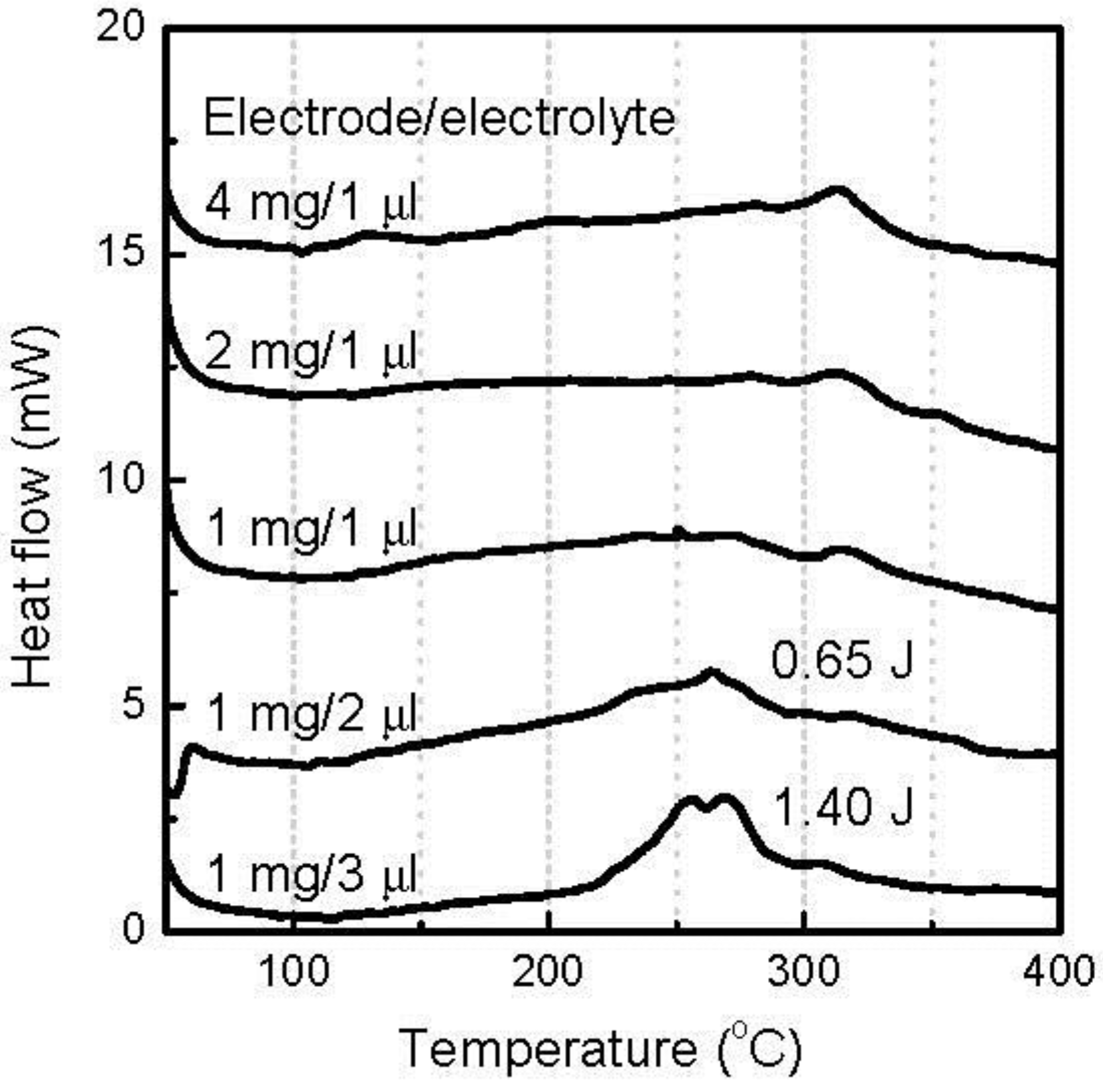
Figure 3 presents the DSC curves of the mixtures of initial cathodes and the electrolyte at various ratios. The most distinguished exothermic peaks were observed in the temperature range of 220–280 °C, with a mixture of 1 mg cathode and 3 μL electrolyte. As the electrolyte in the mixture decreased, the peaks faded rapidly. According to our previous report [
31], it was easy to find that these DSC profiles were similar to that obtained with the neat electrolyte during DSC analysis, including peak position and shape. Therefore, these peaks should be attributed to the thermal decomposition of the coexisting electrolyte. However, it was noticed that the exothermic heat of these peaks was only 1.40 J, much lower than the 2.24 J of the 3 μL neat electrolyte [
31]. Moreover, when the coexisting electrolyte decreased to 1 μL, no discernible thermal peak was observed in this temperature range. These results suggested that the fresh FeOF cathode powder reacted with the electrolyte at an elevated temperature. Accordingly, an exothermic peak appeared at 315 °C, and increased with the coexisting cathode amount. In the viewpoint of the safety, due to the reactions between the fresh FeOF cathode and the electrolyte, the mixture showed less thermal risk than the neat electrolyte at elevated temperature.
By controlling the cutoff voltage for the discharge procedure, FeOF cathodes with different lithiation levels were obtained.
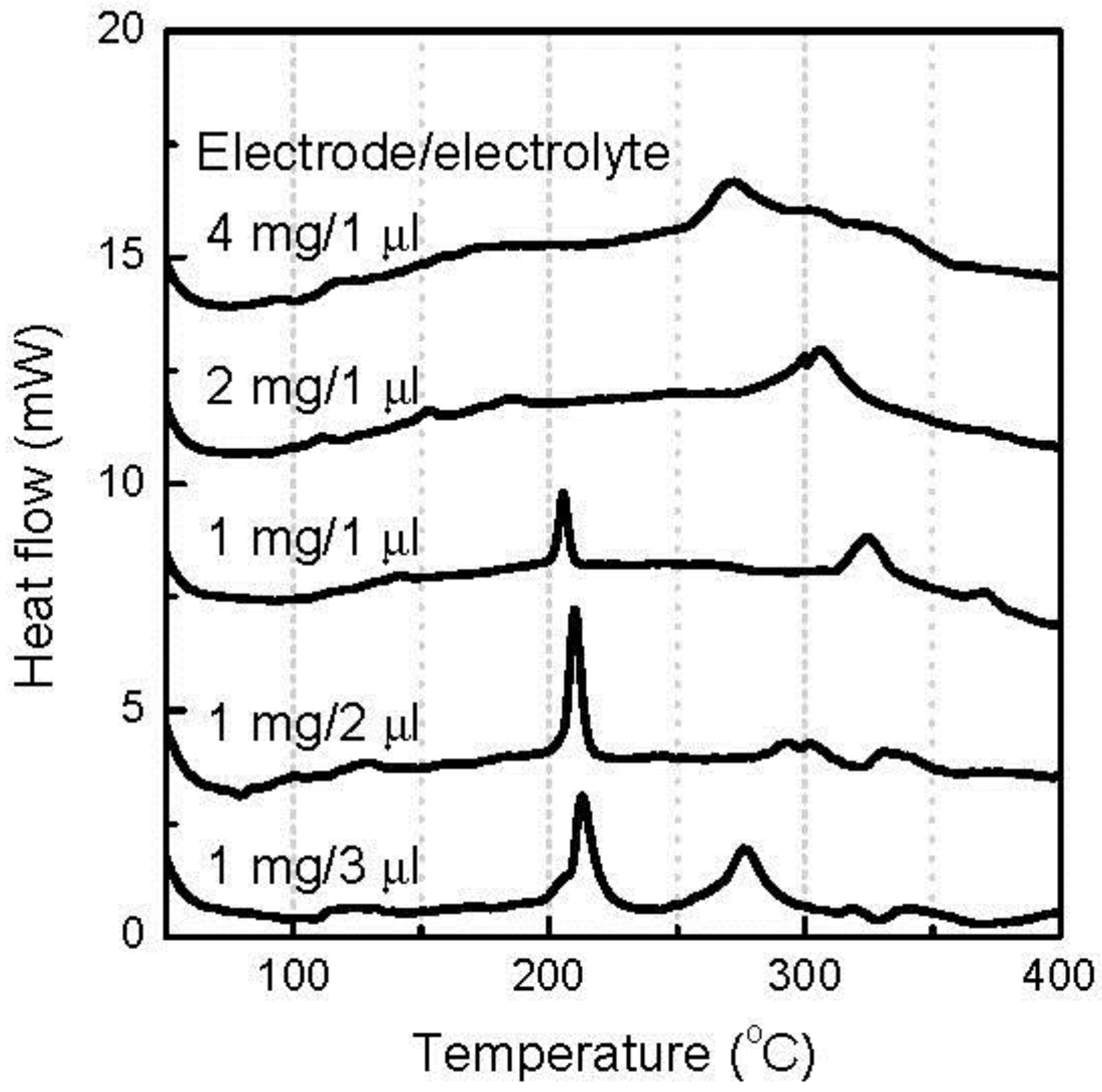
Figure 4 shows the DSC curves of the various amounts of discharged FeOF cathode down to 2.0 V with the associated electrolyte. Theoretically, the cathode consists of almost 50:50 mol% mixture of FeOF and LiFeOF [
29]. A new sharp exothermic peak appeared at about 210 °C, indicating, as we expected, a higher reaction activity of the 0.6Li-inserted FeOF cathode than the fresh one. This peak vanished with the increasing ratio of the cathode over the electrolyte. Instead, a wide exothermic plateau starting from 100 °C gradually became apparent. Obviously, besides Li-inserted cathodes, enough electrolyte was necessary for the generation of the exothermic peak at 210 °C. When the coexisting cathode increased to 4 mg, its overabundance induced mild exothermic peaks at temperatures above 250 °C. In contrast, when 3 μL electrolyte was mixed with 1 mg cathode, an exothermic peak appeared at 280 °C, which might be attributed to the thermal decomposition of residual electrolyte.
With the further decrease of the cutoff voltage to 1.3 V, 1.4Li was introduced into the FeOF cathode and caused a conversion reaction.
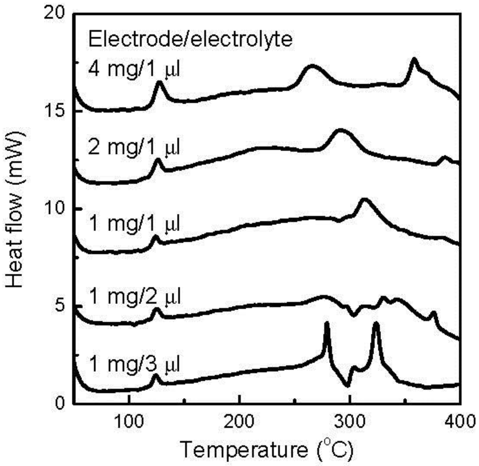
Figure 5 shows the DSC curves of the various amounts of discharged FeOF cathode down to 1.3 V with the associated electrolyte. The data could be divided into two groups: one for the samples containing 1 mg cathode, while the coexisting electrolyte varied from 1 μL to 3 μL, and one for the samples containing 1 μL electrolyte, while the cathode varied from 1 to 4 mg. In the first group, small exothermic peaks with similar intensity were distinguished, with all samples at a low temperature of 125 °C. At the same time, the peaks in the temperature range of 250–350 °C were found to vary with the amount of coexisting electrolyte. When the coexisting electrolyte was over 2 μL, two presentative exothermic peaks appeared around 300 °C. In the second group, the same exothermic peaks at 125 °C were detected with all of the samples similar to that in the first group, but the peak intensity showed a proportional relationship to the amount of cathode in the mixture. The same peaks were hardly observed for the discharged cathode down to 2.0 V, as shown in
Figure 4, so the exothermic peaks at 125 °C should be attributable to the reactions between the discharge products of the conversion reaction in the FeOF cathode and the associated electrolyte. Besides the increasing peaks at 125 °C, a large amount of cathode also induced a peak shift from 320 °C to 270 °C, and the appearance of a new peak at a temperature higher than 350 °C. It was also noticed that the cathode/electrolyte ratio, besides the mass of the mixture, directly affected the thermal behavior of the mixture.
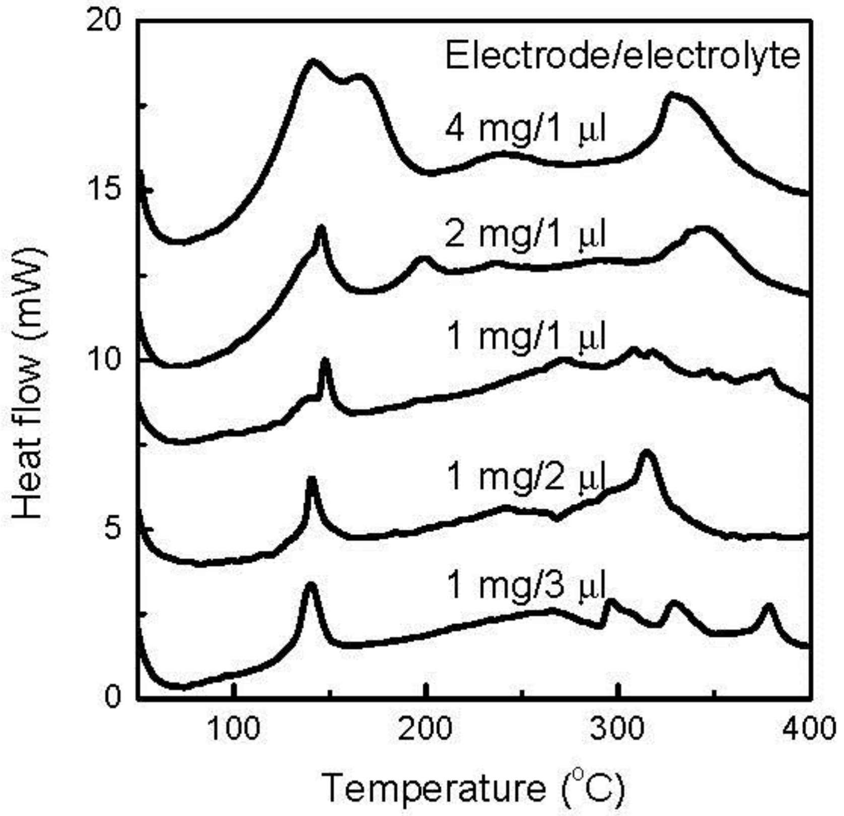
When the discharge cutoff voltage decreased to 0.7 V, 2.7Li was introduced to the FeOF cathode and caused a near-theoretical conversion reaction. Accordingly, the thermal characteristics of the cathode were determined by the products of the conversion reaction.
Figure 6 shows the DSC curves of the various amounts of discharged FeOF cathode down to 0.7 V with the associated electrolyte. When the amount of the cathode in the mixture remained at 1 mg, a larger amount of coexisting electrolyte induced a higher exothermic peak at about 150 °C, but the effect was limited. The heat increased from 0.34 J to 0.44 J, with the increase of the electrolyte from 1 μL to 3 μL. Moreover, no drastic heat was generated in a higher temperature range with the increase of electrolyte. In contrast, the cathode increase showed a strong effect on the thermal stability of the mixture. As the cathode amount increased, the most striking feature was the rapid rise of the exothermic peaks centered at 150 °C. When the cathode was added from 1 to 4 mg in the mixture, the heat amount in the temperature range of 100–200 °C increased from 0.34 to as high as 3.01 J. Obviously, there was not a linear relationship between the peak intensity and the cathode amount. Indeed, the amount of generated exothermic heat was exponentially proportional to the amount of cathode involved. Simultaneously, a gradual variation in the peak shape was also observed. Moreover, several exothermic peaks appeared at higher temperatures, but the intensities were much smaller than that of the peak at 150 °C. So, the thermal risk caused by the fully converted FeOF cathode mainly existed at a temperature range lower than 200 °C.
Charged FeOF cathodes with different cycle depths were obtained by discharging the fresh FeOF cathode down to 2.0, 1.3, and 0.7 V, respectively, and then charging it up to 4.0 V. Ideally, the thermal behavior of the charged cathode should be similar to that of the initial cathode.
Figure 7 shows the DSC curves of the various amounts of charged cathodes with the associated electrolyte. Although the DSC curves varied with the cycle depth and the cathode/electrolyte ratio, three points can be summarized from this figure. First, when coexisting with abundant electrolytes, the charged cathode gave sharp exothermic peaks, which had varying peak intensities and positions on the cycle depth, in the temperature range of 180–250 °C. Second, the overabundant electrolytes thermally decomposed and gave an exothermic peak at about 280 °C, regardless of the cathode cycle depth. Third, when the cathode was overabundant, mild exothermic heat was found in a wide temperature range of 240–350 °C, while the heat amount increased with increasing cycle depth. Although there are discrepancies in the DSC profile between the discharged FeOF cathode down to 2.0 V (
Figure 4) and the inital FeOF (
Figure 3), the former showed a similar DSC profile to the FeOF cathode charged up to 4.0 V after discharge down to 2.0 V, as shown in
Figure 7. Obviously, this phenomenon was attributed to the irreversible Li ions in the cathode. From the electrochemical charge/discharge profiles, the charged FeOF cathodes after discharge down to 2.0 and 1.3 V have similar irreversible capacities. Our previous XRD study [
29] also found that a charged FeOF cathode after discharge down to 1.3 V has a similar XRD spectrum to that of the discharged cathodes down to 1.8 V. These results also indicated that the irreversible Li ions remained in the electrode as a Li-Fe-O intermediated phase. On the other hand, for the charged cathode after discharge down to 0.7 V, a much larger irreversible capacity was obtained during electrochemical cycling. Accordingly, obvious exothermic heat was obtained at about 130 °C with the mixture containing the cathode. This suggests the remaining of some irreversible Li ions as a conversion reaction product in the charged FeOF cathode.
From the DSC analysis, it was noticed that the converted FeOF cathode reacted with the associated electrolyte and gave exothermic heat at a low temperature of about 150 °C. Moreover, the exothermic heat generation was exponentially proportional to the amount of involved cathode. As the exothermic reaction happened at a rather low temperature, it would show very serious adverse effect to the thermal safety of the battery. Therefore, it is necessary to elucidate the mechanism underlying exothermic heat generation. Theoretically, there are three kinds of reaction products in the fully converted FeOF cathode: LiF, Li
2O, and nano-sized metal Fe particles. To evaluate their roles in dangerous exothermic heat generation, the thermal behaviors of the corresponding pure chemicals in the electrolyte were analyzed by DSC.
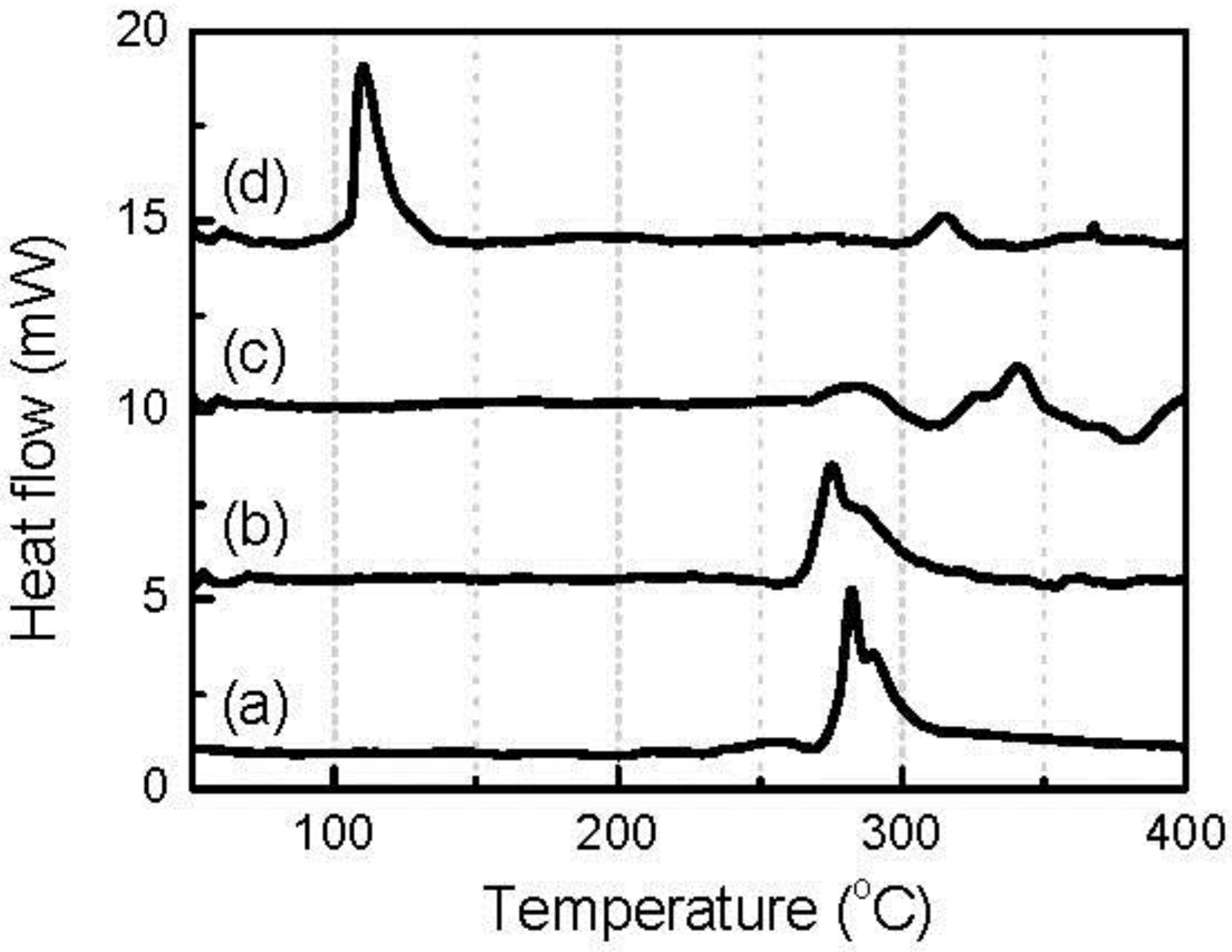
Figure 8 shows the DSC curves of given amounts of LiF, Li
2O, and nano-Fe particles mixed with 1 μL of 1 mol dm
−3 LiPF
6/EC-DMC solution. The amount of each solid reagent was controlled to be the same as that theoretically contained in 1 mg fully converted FeOF cathode. For reference, the figure also shows the DSC curve of 1 μL electrolyte. When 0.17 mg LiF was mixed with the electrolyte, the obtained DSC curve showed a high degree of similarity to that obtained with the neat electrolyte. This indicated that LiF was thermally stable in the electrolyte, as expected. Nano-sized metal particles are well known to be flammable reagents, and are therefore supposed to be unstable at elevated temperatures. During DSC analysis, nano-Fe particles actually reacted with the electrolyte, but the reactions happened at a temperature higher than 270 °C, and included some exothermic ones. The first reaction had an onset temperature of about 270 °C and was exothermic. This temperature was quite close to that of the thermal decomposition of the electrolyte. It was supposed that PF
5 was generated from the thermal decomposition of the electrolyte first, and then the nano-Fe was oxidized by this strong oxidizer. Fortunately, these exothermic reactions were mild, and the heat emission was small. In the case of Li
2O, the situation was the most serious. When DSC analysis was carried out on the mixture of 0.20 mg Li
2O and 1 μL electrolyte, major exothermic heat was generated at a low temperature of about 120 °C, and almost no exothermic heat was found at elevated temperature, which would have been caused by the decomposition of the electrolyte. This indicates that the Li
2O powder reacted with the electrolyte rapidly at about 120 °C, and gave out large exothermic heat. Based on the above analysis, it was evident that the Li
2O generated from the conversion reaction caused the major thermal risk of the converted FeOF cathode.
As Li
2O will be generated in all oxygen-containing conversion-type oxide cathode materials, it could be deduced that a similar thermal risk will exist in this kind of active material for Li-ion batteries. To evaluate the suppression of thermal risk by the replacement of the oxygen with fluorine, the thermal stabilities of the FeOF cathode and its oxygen-free counterpart, FeF
3, were compared in their fully discharged states. According to our previous reports [
22,
23,
24], FeF
3 showed a rather low thermal risk in the associated electrolyte because of the absence of an oxygen component. Although discharged FeF
3 was found to react with the electrolyte and give some exothermic heat at 120 °C, the main exothermic reaction of the mixture came from the thermal decomposition of the overabundant electrolyte at about 270 °C. Besides FeF
3, the LiFePO
4 cathode was also used as a comparison reference here, because LiFePO
4 has been widely used as a thermally stable cathode material for Li-ion batteries. LiFePO
4 was reported to have rather good thermal stability up to 500 °C without a coexisting electrolyte [
23]. However, when it was mixed with electrolytes, dominant exothermic heat was observed in a temperature range of 250–350 °C for the charged LiFePO
4 cathode, and 220–330 °C for the discharged LiFePO
4 cathode, and increased with the amount of coexisting electrolytes. In this study, the LiFePO
4 cathode in its unstable charged state was used for quantitative comparison.
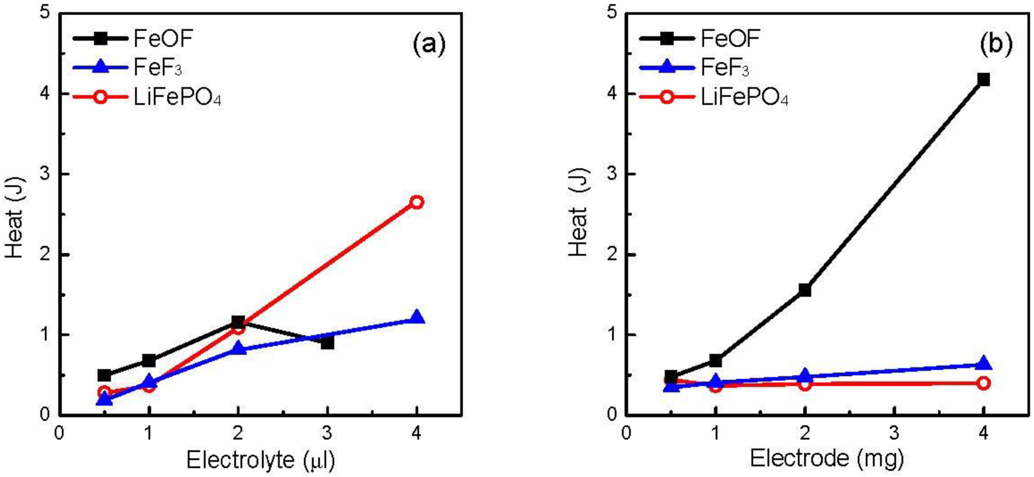
Figure 9a shows the total heat generation of 1 mg cathode with various amounts of electrolytes. Both the FeF
3 and LiFePO
4 cathodes showed higher heat generation with the electrolyte increase, as did the FeOF cathode before a break point at 3 μL. After the break point, due to the absence of drastic reactions in the high-temperature range, the FeOF mixture generated less heat than the two counterparts, especially LiFePO
4. In contrast, when the coexisting cathode was superfluous in the mixture, the situation was completely different.
Figure 9b shows the total heat generation of the various amounts of cathode with 1 μL electrolyte. For the FeF
3 and LiFePO
4 cathodes, the cathode increase had a very slight effect on the total heat generation from the mixtures. However, the increase of the fully discharged FeOF cathode induced much larger heat generation than that for the other two cathodes, due to the exothermic reactions between converted Li
2O and the electrolytes. When the cathode increased to 4 mg, the total heat amount was about seven times larger than that of the FeF
3 cathode. It strongly suggests that the thermal stability should be finally attributed to the oxygen content of the conversion-type cathode active material. By combining the results of
Figure 9a,b, it could be deduced that oxygen-containing conversion-type cathode materials have higher thermal risk than oxygen-free ones, but the thermal risk can be reduced by optimization of the cathode/electrolyte ratio in the cell.


