3.1. Electrochemical Performances for Electrolytes with Cs2CO3 Addition
Generally, KOH solutions with concentrations varying from 4.0 M to 8.5 M are used for Ni/MH batteries in the research field and for commercial applications [
11,
56,
57,
58]. In this study, the electrolyte concentration (KOH + Cs
2CO
3) is fixed at 6.77 M. Concentrations of KOH and Cs
2CO
3 in various electrolytes are shown in
Table 2.
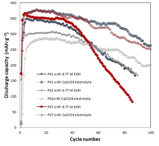
The effects of Cs
2CO
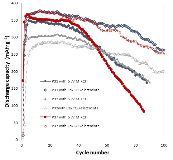
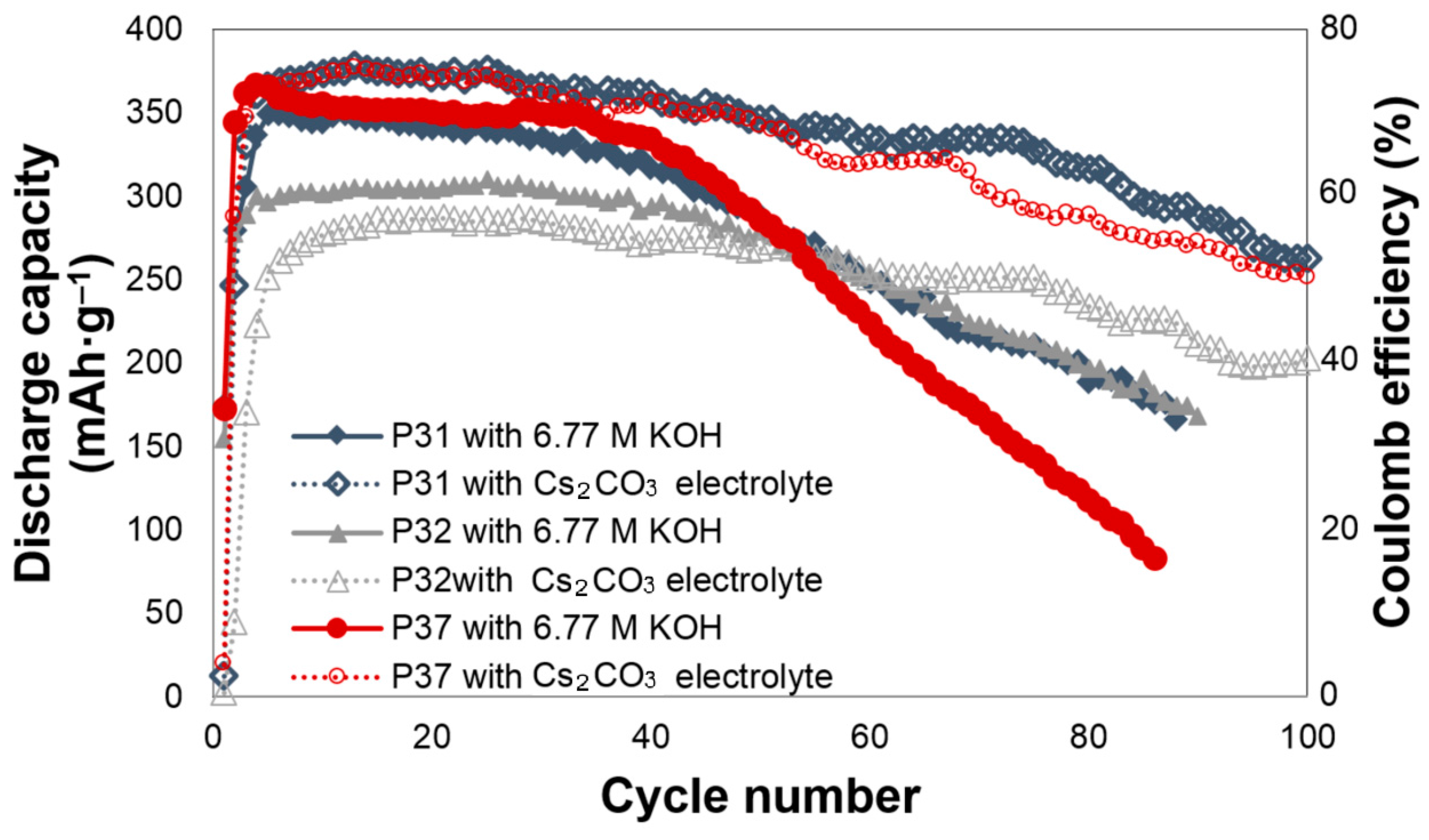
3 addition on the electrochemical performances of alloys P31, P32, and P37 are shown in
Figure 1. All of the cells require approximately three to five cycles to be activated. For alloy P31, Cs
2CO
3 slightly increases the initial discharge capacity, and greatly decreases the degradation. The initial discharge capacities of alloy P31 in the 6.77 M KOH and 6.44 M KOH + 0.33 M Cs
2CO
3 electrolytes are 349 and 375 mAh·g
‒1, respectively. In the 6.77 M KOH electrolyte, the capacity of alloy P31 begins to fade after the 20th cycle, while the capacity fade begins at the 55th cycle in the 6.44 M KOH + 0.33 M Cs
2CO
3 electrolyte. The same trend was observed in alloy P37, where the addition of Cs
2CO
3 increases the initial discharge capacity from 364 mAh·g
‒1 to 375 mAh·g
‒1, and changes the beginning of the capacity fade from the 30th to the 65th cycle. For alloy P32, Cs
2CO
3 does not increase the initial discharge capacity; however, it greatly decreases the decay, as shown in
Figure 1. In comparison to alloy P32, both alloys P31 and P37 contain Al, raising the possibility that the presence of Al results in the alloy surface reacting with the CO
32− ions in the electrolyte and forming Al
2(CO
3)
3. Al
2(CO
3)
3, which is known to be unstable in water [
59]. Such phenomenon may assist in the dissolution of Al into the highly alkaline electrolyte, and therefore increase the reactive surface area.
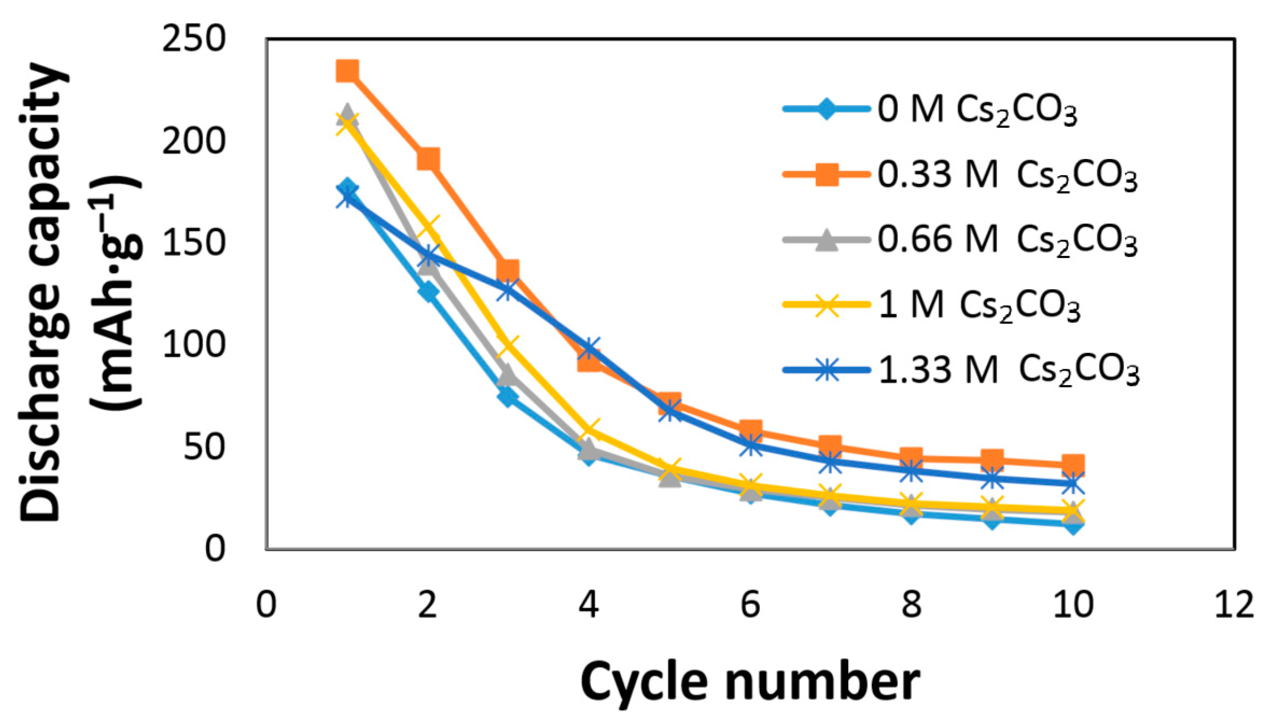
The effects of Cs
2CO
3 on the AR3 alloy electrode performances are shown in
Figure 2. The AR3 MH alloy is very reactive to the KOH electrolyte due to the alloy’s high content of Mg and the high porosity caused by the mechanical alloying preparation [
12]. A rapid decay in the KOH electrolyte was previously reported [
5,
6,
12].
Figure 2 shows an increase in initial discharge capacity and a decrease in capacity decay with the addition of Cs
2CO
3. The discharge capacity, degradation, and HRD of the Cs
2CO
3-containing electrolytes are normalized to those of the 6.77 M KOH electrolyte and presented in
Table 2. The optimized conditions were obtained at the concentration of 6.44 M KOH + 0.33 M Cs
2CO
3, which exhibited the highest discharge capacity and lowest degradation.
Table 2 also indicates that a small addition of Cs
2CO
3 has an insignificant effect on HRD, while a high concentration of Cs
2CO
3 in the electrolyte has a negative influence on HRD.
3.2. Effects of Cs2CO3 Addition on MgNi Alloy
Weights of the cycled AR3 alloy electrodes were measured. After 10 cycles, weights of the alloy electrodes cycled in all of the electrolytes increased due to surface metal oxidation and the deposition of some salts. Surface metal oxidation during charge leads to the formation of surface metal hydroxide, such as Mg(OH)
2 [
11,
16]. The majority of salt depositions are carbonates and bicarbonates [
52]. Weight gains of the alloy electrodes cycled in the Cs
2CO
3-containing electrolytes are normalized to that in the 6.77 M KOH electrolyte and presented in
Table 3. As the Cs
2CO
3 concentration in the electrolyte increases, the weight gain decreases. The addition of Cs
2CO
3 changes the physical and chemical properties of the electrolyte. Cs
2CO
3 reacts with the MH alloy surface during electrochemical cycling, which results in a protective layer and greatly decreases the reaction rate of metal oxidation. Therefore, the weight gain due to surface oxidation (listed in
Table 3) is substantially reduced by the addition of Cs
2CO
3 in the electrolyte.
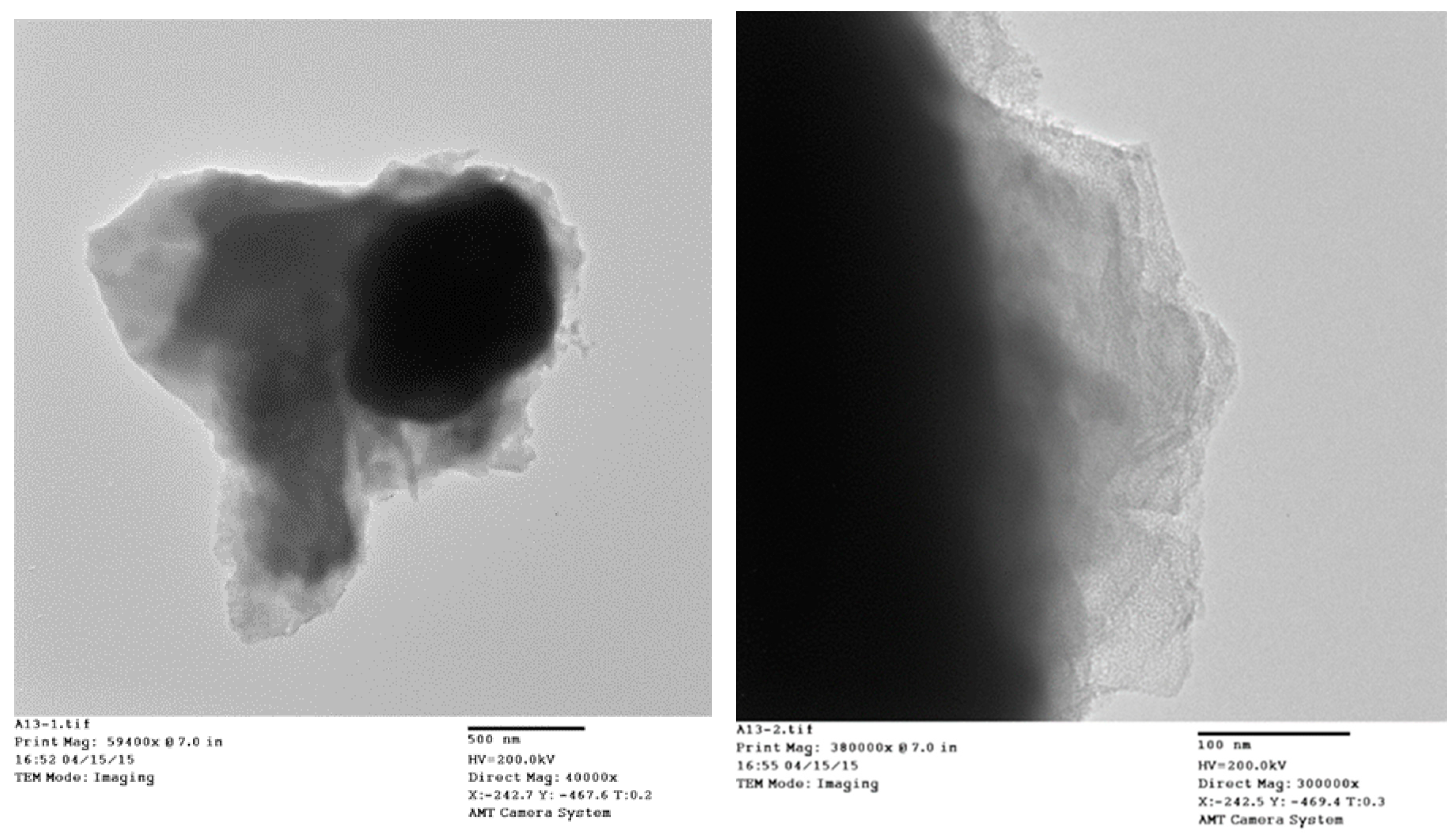
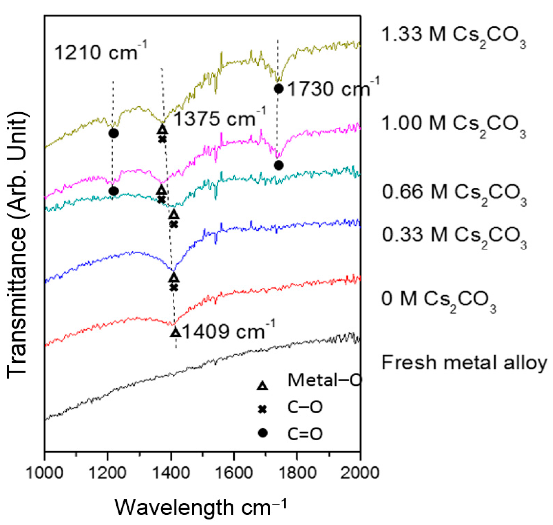
TEM micrographs of the cycled AR3 indicate that a thin layer of fluffy material covers the surface of the MH alloy (
Figure 3a,b). FTIR was used to characterize the surface structure, and the results are shown in
Figure 4. For the fresh MH alloy, there is no clear diffraction peak, which indicates that the alloy surface is clean. For the alloy cycled in the 6.77 M KOH electrolyte, a peak at approximately 1409 cm
‒1 is observed, which is related to the vibration of surface metal–O bonds [
60]. For the electrode cycled in the 6.44 M KOH + 0.33 M Cs
2CO
3 electrolyte, the same peak is seen, but shifted slightly to a lower wavelength, implying a decrease in bond strength. However, the peak intensity increases, which suggests the appearance of C–O bonds on the alloy surface, since the stretching vibration of the C–O bond occurs at approximately the same wavelength [
61] as the metal–O bond. With further increases in concentration of Cs
2CO
3 in the electrolyte, the metal–O bond becomes weaker with the peak shifting even lower, to around 1375 cm
‒1, and the amount of C–O bond decreases, as shown by a reduction in peak intensity compared with the electrode cycled in the 6.77 M KOH electrolyte. Moreover, peaks at approximately 1730 and 1210 cm
‒1 start to appear as the content of Cs
2CO
3 increases, which is related to the vibration of the C=O bond in carbonate [
61]. FTIR results demonstrate the changes in the surface groups on the MH alloy surface with varying Cs
2CO
3 concentration.
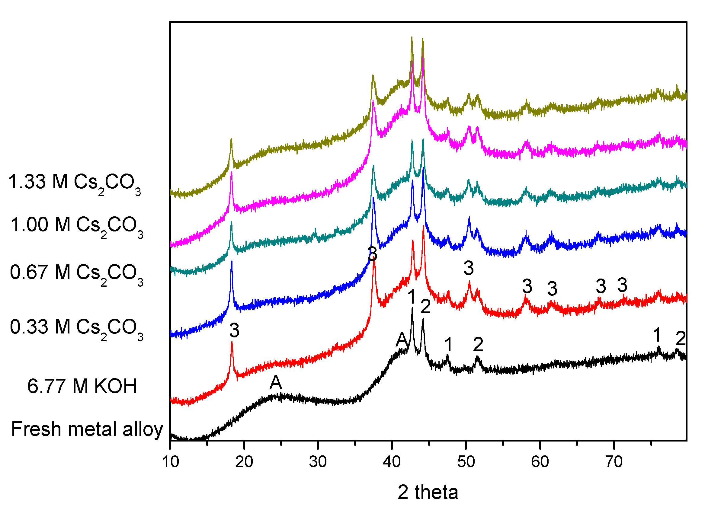
XRD patterns before and after electrochemical cycling are shown in
Figure 5. As our previous study has shown [
62], the two broad peaks at approximately 23° and 42° (marked as “A”) are from the broadening of the MgNi
2 and Mg
2Ni phases. These two broad peaks exist in all of the cycled AR3 samples, suggesting high stability for MgNi
2 and Mg
2Ni during cycling. Except for the peaks marked as “A”, there are some strong peaks related to metallic Mn and Co (marked as “1” and “2” in
Figure 5, respectively). Mn and Co fine particles are the remnants from the mechanical alloying process, and act as catalysts for hydrogen storage to enhance the electrochemical capacity [
11]. Mg(OH)
2 is also found in all of the cycled AR3 (marked as “3” in
Figure 5), and is the oxidation product from high-Mg AR3. The peaks at approximately 18° and 33° are the (001) and (100) diffraction peaks for the hexagonal Mg(OH)
2. Results from the phase deconvolution by Jade 9.0 software (MDI, Livermore, CA, USA) are summarized in
Table 4 and
Table 5. While no obvious trends are found in the crystallite sizes of phases with cycling in different electrolytes, clear trends are observed in phase abundances. An increase in Cs
2CO
3 concentration in the exchange of KOH reduces both the amount of Mg(OH)
2 (decrease in oxidation) and the Mg
2Ni-to-MgNi
2 ratio (last column in
Table 5). The Mg
2Ni phase is more oxidable compared with the MgNi
2 phase, due to its higher Mg content. Upon contacting the KOH electrolyte, the Mg
2Ni phase is oxidized into Mg(OH)
2, which results in a reduction in the Mg
2Ni-to-MgNi
2 ratio from 1.50 to 0.67. Partial replacement of the corrosive KOH with Cs
2CO
3 increases the Mg
2Ni-to-MgNi
2 ratio, which is another indication of decrease in alloy oxidation.
The chemical compositions of fresh and cycled MH alloys determined by ICP are compared in
Table 6. Similar to the results in previous reports, the bulk composition changes slightly after cycling [
5,
6]. The loss of Mg occurs at approximately 1.5%, and results in an increase in the concentrations of other elements.
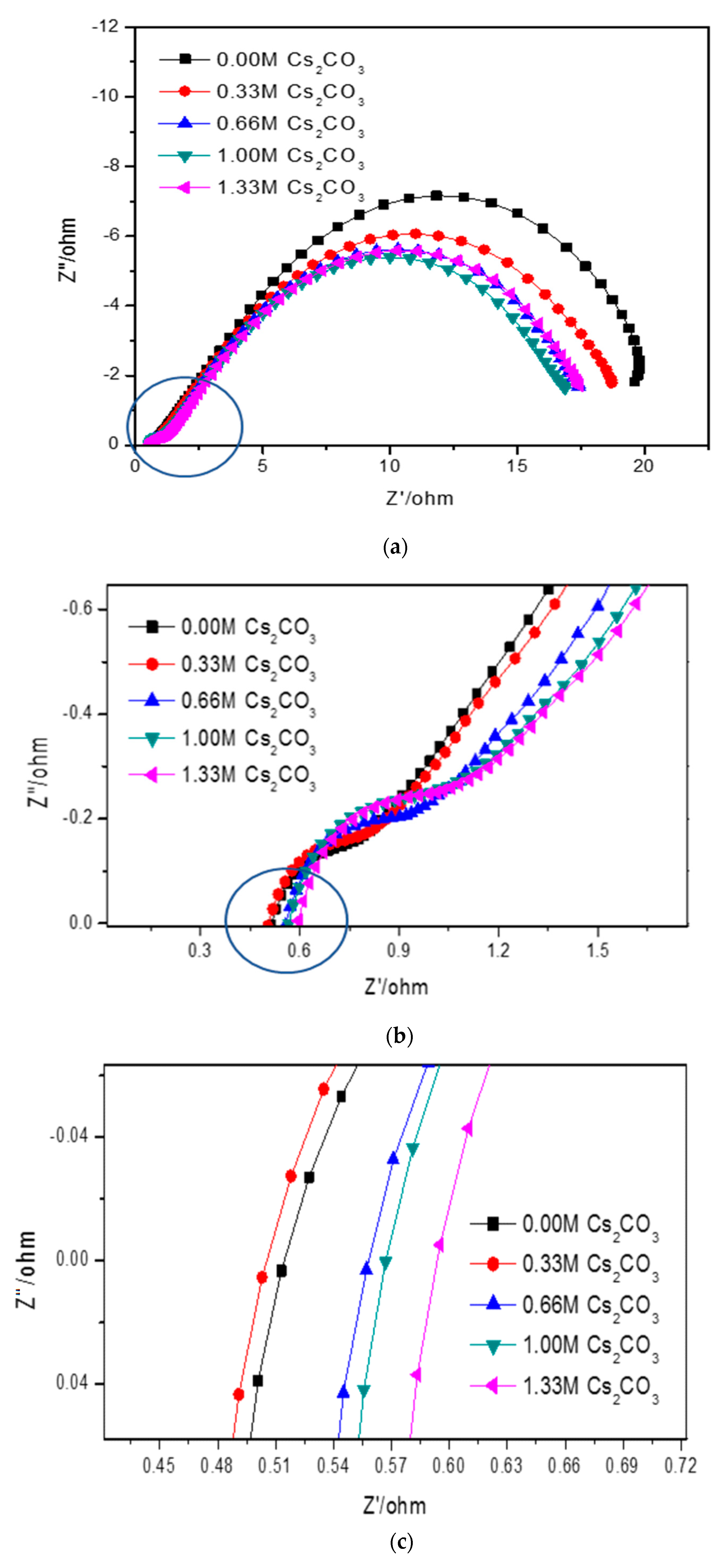
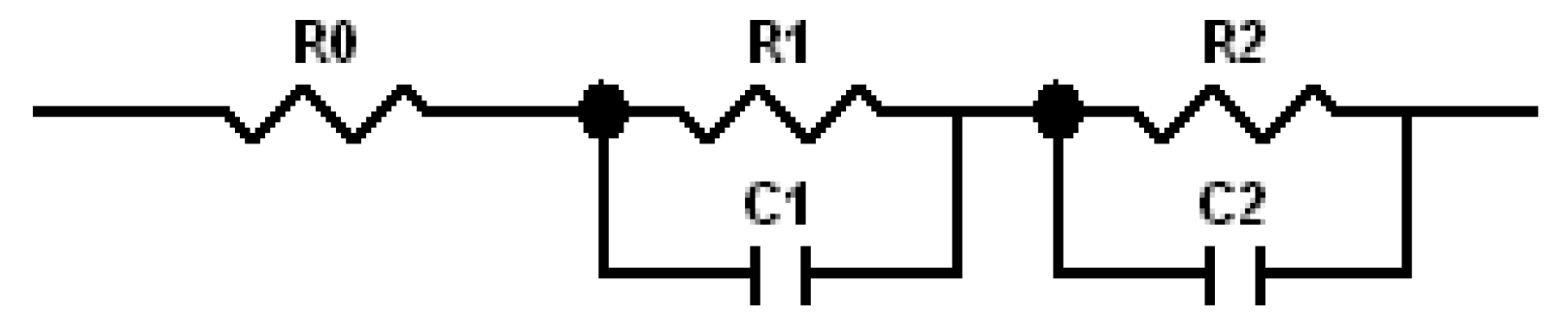
Cole–Cole plots obtained from the alternating current (AC) impedance measurements are shown in
Figure 6. The reported equivalent circuit model for Ni-MH batteries using Mg-based alloy anodes is shown in
Figure 7 [
63,
64,
65,
66,
67]. Constant phase elements are used in this circuit model, due to the inhomogeneity properties of the electrode surface, such as porosity and roughness. Results obtained from the Cole–Cole plots are presented in
Table 7.
R0 represents the resistance of ions traveling through the electrolyte and separator. The electrolyte containing 6.44 M KOH + 0.33 M Cs
2CO
3 shows the lowest
R0, which is consistent with its high discharge capacity, low degradation, and similar HRD compared with the 6.77 M KOH electrolyte.
R1 is the resistance among alloy particles and increases as the Cs
2CO
3 concentration increases.
R2 is the whole electrode resistance, and the addition of Cs
2CO
3 greatly decreases
R2 compared with the pure KOH electrolyte.
C1 represents the particle capacitance, which is closely related to the contact area among alloy particles. With increasing Cs
2CO
3 concentration,
C1 decreases.
C2 is the electrode capacitance, which is an indication of the amount of the active area in the electrode.
Table 7 shows that the addition of Cs
2CO
3 decreases
C2 as well. The product of
R2 and
C2 represents the electrode activity performance [
68,
69], and a smaller value suggests better electrochemical performances.
Table 7 shows an optimized
R2·
C2 value at 5.77 M KOH + 1.00 M Cs
2CO
3.
3.3. Discussion
Results obtained from the current study indicate that the addition of Cs
2CO
3 alters the chemical and physical properties of the KOH electrolyte. As shown in
Figure 6 and
Table 7, an addition of 0.33 M Cs
2CO
3 decreases the solution resistance. Even if the electrolyte concentration was fixed at 6.77 M, the number of conductive ions increased with the addition of Cs
2CO
3. Therefore, the 6.44 M KOH + 0.33 M Cs
2CO
3 electrolyte has a decreased resistance and increased conductivity. While a low Cs
2CO
3 concentration promotes proton transfer in the system and improves both the discharge capacity and cycling performance, a higher Cs
2CO
3 concentration increases the solution resistivity due to the increased concentrations of larger cations (Cs
+) and anions (CO
32−) in the electrolyte, according to Stokes’ Law [
12].
Cs
2CO
3 also changes the alloy surface structure during cycling. The FTIR results show that a small addition of Cs
2CO
3 decreases the strength of surface metal–O bond, but generates the C–O bond on the alloy surface. By further increasing the Cs
2CO
3 concentration, the C=O bond begins to appear, in relation with decreasing C–O bond. The changes in surface groups by electrolyte additive consequently change the chemical and physical properties of the alloy particles. In our previous work [
52], 32 types of salt additives in KOH electrolytes were tested, and some oxyacid salts were reported to create more surface groups that promoted proton transfer. In the current study, the addition of Cs
2CO
3 provides C–O and C=O bonds as new active sites for proton transfer. However, protons bond to the two active sites differently; protons are covalently bound to C–O, but electrostatically bound to C=O [
52,
66]. With the stronger attraction to C–O, more protons can be bound and later transferred (driven by voltage). Therefore, the largest number of C–O bonds, which occur at a small addition of Cs
2CO
3 (6.44 M KOH + 0.33 M Cs
2CO
3), were demonstrated to be the most effective in improving the electrochemical performances among all of the electrolytes tested in the current study.
The addition of Cs
2CO
3 also changes the bulk structure of the alloy particles. The TEM images show a layer of solid covering the MH alloy particle (
Figure 3), which ranges from 20 nm to 500 nm. This surface layer decreases the contact area among alloy particles (as shown by the decrease in
C1) and increases the barrier for proton transfer among the particles (as shown by the increase in
R1). The ICP results show that a small amount of Cs
2CO
3 results in this decrease, but further increases in Cs
2CO
3 concentration increase the loss of Mg after cycling. For the pure KOH electrolyte, the alloy particles are covered by Mg(OH)
2. However, a small addition of Cs
2CO
3 reduces the particle size of Mg(OH)
2 on the surface, as indicated by the increase in full width at half maximum of the Mg(OH)
2 peaks (
Figure 5). Smaller Mg(OH)
2 crystals are more strongly adsorbed on the surface of the MH alloy, which is not easily removed from the electrolyte, and also protects the bulk alloy from further oxidation. As the Cs
2CO
3 concentration further increases in the electrolyte, more MgCO
3 starts to form on the alloy surface. Since the solubility of MgCO
3 in KOH solution is greater than that of Mg(OH)
2, the loss of Mg occurs at a higher rate at higher Cs
2CO
3 concentrations. Therefore, high Cs
2CO
3 concentrations are not suggested for Mg–Ni alloys. On the other hand, if properly balanced with the loss of Mg, an appropriate amount of carbonate formation by adding Cs
2CO
3 can promote the dissolution of surface oxidation products and consequently reveal a clean metal surface exposed to the electrolyte, which can lead to a decrease in electrode resistance (as shown by the decrease in
R2 as the Cs
2CO
3 concentration increases).


