Corrections of Voltage Loss in Hydrogen-Oxygen Fuel Cells


Division for Experimental Physics, School of Nuclear Science & Engineering, National Research Tomsk Polytechnic University, Lenina Ave. 43, 634034 Tomsk, Russia
*
Author to whom correspondence should be addressed.
Batteries 2020, 6(1), 9; https://doi.org/10.3390/batteries6010009
Submission received: 21 November 2019
/
Revised: 31 January 2020
/
Accepted: 1 February 2020
/
Published: 6 February 2020
Abstract
:Normally, the Nernst voltage calculated from the concentration of the reaction gas in the flow channel is considered to be the ideal voltage (reversible voltage) of the hydrogen-oxygen fuel cell. The Nernst voltage loss in fuel cells in most of the current literature is thought to be due to the difference in concentration of reaction gas in the flow channel and concentration of reaction gas on the catalyst layer at the time as when the high net current density is generated. Based on the Butler–Volmer equation in the hydrogen-oxygen fuel cell, this paper demonstrates that Nernst voltage loss caused by concentration difference of reaction gas in the flow channel and reaction gas on the catalyst layer at equilibrium potential. According to the relationship between the current density and the concentration difference it can be proven that Nernst voltage loss does not exist in hydrogen-oxygen fuel cells because there is no concentration difference of reaction gas in the flow channel and on the catalytic layer at equilibrium potential when the net current density is zero.
1. Introduction
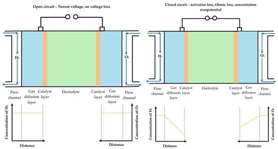
A fuel cell is a chemical device that direct converts the chemical energy contained in fuel into electric energy. It is the fourth power generation technology after hydroelectric, thermal, and atomic power generation. Since the fuel cell converts the Gibbs free energy of the chemical energy of the fuel into electric energy through an electrochemical reaction, it is not limited by the effect of the Carnot cycle, so the efficiency is high [1]. The two parameters that are closely related to performance of the fuel cell are the output voltage and current of the cell. Under a certain temperature, pressure, and concentration of the substance, the maximum theoretical voltage that the fuel cell can output is determined by the Nernst equation, which is called reversible voltage (Nernst voltage) [2,3,4]. However, there are a series of irreversible processes in actual fuel cells. These irreversible processes lead to a series of corresponding irreversible voltage losses in the fuel cell. The cell voltage losses comprise of three major components: (1) Activation loss (loss due to electrochemical reaction), which is the lost Galvani potential in order to generate a net current; (2) Ohmic loss (loss due to ionic and electronic conduction), which is linear related to the current; (3) Concentration loss (loss due to mass transport of the gases from the flow channel to the catalytic layer) [5,6,7,8,9,10,11,12,13]. Parameters used for modeling the hydrogen-oxygen fuel cell are presented in Table 1. The literature considers that concentration loss leads to two different voltage losses: concentration overpotential and Nernst voltage loss [10]. In most of the literature, it is believed that Nernst voltage loss ( or ) caused by concentration loss are due to the concentration difference of reaction gas in the flow channel and on the catalytic layer at the time at which the net current density is generated (closed circuit) [14,15,16,17,18,19,20,21,22,23]. Thus, the cell voltage loss with respect to the Nernst voltage at inlet conditions are believed in the literature to be interpreted in terms of four components: (1) Nernst voltage loss; (2) ohmic loss; (3) activation loss; and (4) concentration overpotential [14]. However, it should be noted that according to the definition of Nernst voltage, the Nernst voltage is calculated at inlet conditions without a net current, i.e., the Nernst voltage is an open circuit voltage [3]. It can be proved that in the case of open circuit, the concentration of the reaction gas in the flow channel is the same as that on the catalytic layer, so no concentration loss is generated. When the circuit is closed, although the concentration of the reaction gas on the catalyst layer decreases, it has no effect on the Nernst voltage according to the definition of Nernst voltage. Therefore, concentration loss does not lead to Nernst voltage loss. This result has important significance, especially in the case of a high net current density, when the concentration of the reaction gas on the catalyst layer is much lower than the concentration of the reaction gas in the flow channel, making the so-called Nernst voltage loss () very big, thereby seriously affecting the judgment of the hydrogen-oxygen fuel cell performances.
2. Theoretical Analysis
2.1. Galvani Potential
When the external circuit of the fuel cell is open, the reaction gas is continuously introduced into the flow channel. At this time, the electrode reaction starts on the catalytic layer. Take the anode reaction as an example:
H2 ⇄2 H+ + 2e−,
During the reaction, both the forward reaction and the reverse reaction need to overcome certain activation barriers (Figure 1), even though from the energy point of view the energy of the products is lower than the energy of the reactants (the reaction is spontaneous). However, due to the existence of activation barriers, the reaction rate is still limited. Current density is usually used instead of reaction rate as the basic performance parameter of the fuel cell [24].
The anode current density of the forward electrode reaction is
Since the operating process of fuel cell is considered to be a process with constant temperature and pressure, the decay rate of each reaction in each electrode is the same. Replace f1 by f [25,26]:
The anode current density of the reverse electrode reaction is
During the electrode reaction, the reactants are continuously consumed and the products continuously accumulate. At the same time, electrons accumulate at the metal electrodes, H+ accumulate at the surface of the catalyst layer, an electric field is formed between the metal electrode and the catalytic layer, the energy of the reaction system increases, the activation barrier of the forward reaction and the reverse reaction both changes (Figure 2), the rate of forward reaction decreases, and the rate of reverse reaction increases. α is called transfer coefficient, α expresses how the change in the electrical potential across the reaction interface changes the sizes of the forward versus reverse activation barriers. The value of α is always between 0 and 1. For “symmetric” reactions, α = 0.5. For most electrochemical reactions, α ranges from about 0.2 to 0.5 [25,26].
When current densities of the forward and reverse reaction are equal, the intensity electric field no longer increases and a stable equilibrium potential difference (Galvani potential ∆ϕ1) is achieved between the metal electrode and the catalyst layer [27,28]. At this time the anode current densities have been changed to
The anode exchange current density is
Similarly, the cathode exchange current density is
The Nernst voltage of the hydrogen-oxygen fuel cell is
2.2. Cell Voltage Losses
When the external circuit of the fuel cell is closed, the accumulated electrons are conducted from the anode to the cathode, and the hydrogen ions are transmitted from the anode side of the electrolyte to the cathode side. The electrode potential must be reduced, that is, activation loss. Activation loss is a part of the voltage that must be sacrificed to start the operation of the fuel cell. As the activation loss is generated, the activation barrier for the forward reaction decreases by , and the activation barrier for the reverse reaction increases by , the rate of forward reaction exceeds the rate of reverse reaction and the fuel cell produces a net current density.
Taking into account the influence of the net current generation on the concentrations of reactant and product, net current density is determined by the Butler–Volmer equation [28,29,30]:
In fact, the net reaction rate will affect the surface concentration of reactants and products on the catalyst layer. For example, when the forward reaction rate increases drastically and the reverse reaction rate decreases sharply, the surface concentration of the reactants on the catalyst layer tends to be depleted. Obviously for a certain net current density, the lower the concentration of the reactants on the catalyst layer, the greater the activation loss required to reach the same net current density, which leads to a sharp increase in the demand for additional activation loss. This additional activation loss is the concentration overpotential. At high current densities, the reactants on the catalytic layer are rapidly consumed, which leads to a sharp increase in the need for an activation loss, leading to a big concentration overpotential [31,32,33,34].
When the external circuit of the fuel cell is closed, between the flow channel and the catalyst layer surface, a stable concentration gradient is formed (Figure 3).
At this time, the net current density can be expressed according to the diffusion of reactive gas in the anode electrode [32,33,34,35]:
When , the limiting current density is obtained:
At high current densities, the second term in the Butler–Volmer equation can be discarded. Therefore, the net current density simplifies to
(13) can be expressed in the form of actual anode activation loss:
Theoretical anode activation loss based on the concentration of reactant in the flow channel is
The concentration overpotential of anode caused by concentration loss is
The concentration overpotential calculated by us is the same as the expression presented in literatures.
Obviously, the actual closed-circuit voltage should be
The actual closed-circuit voltage can also be expressed as
According to the Nernst voltage loss expression in the literature, Nernst voltage loss occurs when the net current density is not zero. However, it can be seen from Equation (11) that there is no difference in concentration of reaction gas in the flow channel and concentration of reaction gas on the catalyst layer in the case of open circuit. According to Equation (9), the actual Nernst voltage is the same as the theoretical Nernst voltage, i.e., E0* = E0. Therefore, the concentration loss only leads to the concentration overpotential, not to Nernst voltage loss.
3. Conclusions
From the above discussion, it can be concluded that in the hydrogen-oxygen fuel cell the voltage losses that causes the Nernst voltage to fall can be divided into three categories: (1) activation loss at low current density; (2) the linear Ohmic loss inside the fuel cell; (3) the concentration overpotential due to the intensive decrease of concentration of reactants on the catalytic layer in the high current density. cannot be used as Nernst voltage loss for hydrogen-oxygen fuel cell because the Nernst voltage belongs to an open circuit voltage in essence.
Author Contributions
Conceptualization, J.L.; validation, J.L., V.K. and A.L.; resources, J.L.; writing—original draft preparation, J.L.; writing—review and editing, V.K. and A.L.; funding acquisition, V.K. and A.L. All authors have read and agreed to the published version of the manuscript.
Funding
The research was funded by the Governmental program “Science”, research project No. FSWW-2020-0017.
Acknowledgments
This work was carried out within the framework of the Competitiveness Enhancement Program of National Research Tomsk Polytechnic University.
Conflicts of Interest
The authors declare no conflict of interest.
References
- Derr, I.; Fetyan, A.; Schutjajew, K.; Roth, C. Electrochemical analysis of the performance loss in all vanadium redox flow batteries using different cut-off voltages. Electrochim. Acta 2017, 224, 9–16. [Google Scholar] [CrossRef]
- Miyashita, T. Loss of Gibbs Energy Using Sm-Doped Ceria Electrolytes in SOFCs Considering Local Equilibrium while Ion Hopping. Open Mater. Sci. J. 2009, 3, 47–49. [Google Scholar] [CrossRef] [Green Version]
- Chiodelli, G.; Malavasi, L. Electrochemical open circuit voltage (OCV) characterization of SOFC materials. Ionics 2013, 19, 1135–1144. [Google Scholar] [CrossRef]
- Miyashita, T. A Current-Independent Constant Anode Voltage Loss Using Sm-Doped Ceria Electrolytes in SOFCs. ECS Trans. 2014, 59, 53–61. [Google Scholar] [CrossRef] [Green Version]
- Barnhart, C.J.; Dale, M.; Brandt, A.R.; Benson, S.M. The energetic implications of curtailing versus storing solar- and wind-generated electricity. Energy Environ. Sci. 2013, 6, 2804–2810. [Google Scholar] [CrossRef] [Green Version]
- Calise, F.; Dentice d’Accadia, M.; Palombo, A.; Vanoli, L. Simulation and exergy analysis of a hybrid Solid Oxide Fuel Cell (SOFC)–Gas Turbine System. Energy 2006, 31, 3278–3299. [Google Scholar] [CrossRef]
- Fowler, M.W.; Mann, R.F.; Amphlett, J.C.; Peppley, B.A.; Roberge, P.R. Incorporation of voltage degradation into a generalised steady state electrochemical model for a PEM fuel cell. J. Power Sources 2002, 106, 274–283. [Google Scholar] [CrossRef]
- Rakhtala, S.M.; Ghaderi, R.; Ranjbar Noei, A. Proton exchange membrane fuel cell voltage-tracking using artificial neural networks. J. Zhejiang Univ. Sci. C 2011, 12, 338–344. [Google Scholar] [CrossRef]
- Kundu, S.; Fowler, M.; Simon, L.C.; Abouatallah, R. Reversible and irreversible degradation in fuel cells during Open Circuit Voltage durability testing. J. Power Sources 2008, 182, 254–258. [Google Scholar] [CrossRef]
- Ahmed, K.; Föger, K. Analysis of equilibrium and kinetic models of internal reforming on solid oxide fuel cell anodes: Effect on voltage, current and temperature distribution. J. Power Sources 2017, 343, 83–93. [Google Scholar] [CrossRef]
- Bove, R.; Lunghi, P.; Msammes, N. SOFC mathematic model for systems simulations. Part one: From a micro-detailed to macro-black-box model. Int. J. Hydrog. Energy 2005, 30, 181–187. [Google Scholar] [CrossRef]
- Ranjbar, F.; Chitsaz, A.; Mahmoudi, S.M.S.; Khalilarya, S.; Rosen, M.A. Energy and exergy assessments of a novel trigeneration system based on a solid oxide fuel cell. Energy Conv. Manag. 2014, 87, 318–327. [Google Scholar] [CrossRef]
- Arato, E.; Costa, P. Transport mechanisms and voltage losses in PEMFC membranes and at electrodes: A discussion of open-circuit irreversibility. J. Power Sources 2006, 159, 861–868. [Google Scholar] [CrossRef]
- Sharma, A.K.; Ahmed, K.; Birgersson, E. Nernst voltage losses in planar fuel cells caused by changes in chemical composition: Effects of operating parameters. Ionics 2018, 24, 2047–2054. [Google Scholar] [CrossRef]
- Winkler, W.; Williams, M.C. Basics for Fuel Cell Performance Loss Evaluation. ECS Trans. 2018, 83, 53–69. [Google Scholar] [CrossRef]
- Erilin, I.S.; Smorodova, O.V.; Baikov, I.R.; Kitaev, S.V. Experimental study of fuel cell properties based on current-voltage characteristic. J. Phys. Conf. Ser. 2018, 1111, 012070. [Google Scholar] [CrossRef]
- Gemmen, R.S.; Johnson, C.D. Effect of load transients on SOFC operation-current reversal on loss of load. J. Power Sources 2005, 144, 152–164. [Google Scholar] [CrossRef]
- Noren, D.A.; Hoffman, M.A. Clarifying the Butler–Volmer equation and related approximations for calculating activation losses in solid oxide fuel cell models. J. Power Sources 2005, 152, 175–181. [Google Scholar] [CrossRef]
- Luo, Y.Q.; Jiao, K.; Jia, B. Elucidating the constant power, current and voltage cold start modes of proton exchange membrane fuel cell. Int. J. Heat Mass Transf. 2014, 77, 489–500. [Google Scholar] [CrossRef]
- Au, S.F.; Peelen, W.H.A.; Standaert, F.R.A.M.; Hemmes, K.; Uchida, I. Verification of Analytical Fuel Cell Models by Performance Testing at a 110 cm2 Molten Carbonate Fuel Cell. J. Electrochem. Soc. 2001, 148, A1051. [Google Scholar] [CrossRef]
- Selimovic, A.; Palsson, J. Networked solid oxide fuel cell stacks combined with a gas turbine cycle. J. Power Sources 2002, 106, 76–82. [Google Scholar] [CrossRef]
- Reimer, U.; Lehnert, W.; Holade, Y.; Kokoh, B. Irreversible Losses in Fuel Cells. Fuel Cells and Hydrogen. 2018, pp. 15–40. Available online: https://doi.org/10.1016/B978-0-12-811459-9.00002-5. (accessed on 5 February 2020).
- Greene, E.S.; Chiu, W.K.S.; Medeiros, M.G. Mass transfer in graded microstructure solid oxide fuel cell electrodes. J. Power Sources 2006, 161, 225–231. [Google Scholar] [CrossRef]
- Yi, B.L. Fuel Cell—Principles, Technology, Apply, 1st ed.; Chemical Industry Press: Beijing, China, 2003; pp. 9–13. [Google Scholar]
- Ryan, O.; Suk-won, C.; Whitney, G.C.; Fritz, B.P. Chapter 3 Fuel Cell Reaction Kinetics, In Fuel Cell Fundamentals, 3rd ed.; John Wiley and Sons: Hoboken, NJ, USA, 2016; pp. 85–90. [Google Scholar]
- Colleen, S. PEM Fuel Cell Modeling and Simulation Using MATLAB, 1st ed.; Publishing House of Electronics Industry: Beijing, China, 2013; pp. 12–94. [Google Scholar]
- Reymond, F.; Fermin, D.; Lee, H.J.; Girault, H.H. Electrochemistry at liquid/liquid interfaces: Methodology and potential applications. Electrochim. Acta 2000, 45, 2647–2662. [Google Scholar] [CrossRef]
- Ryan, O.; Suk-won, C.; Whitney, G.C.; Fritz, B.P. Chapter 5 Fuel Cell Mass Transport, In Fuel Cell Fundamentals, 3rd ed.; John Wiley and Sons: Hoboken, NJ, USA, 2016; p. 169. [Google Scholar]
- Cha, Q.X. Introduction to Dynamics of Electrode Process, 3rd ed.; Science Press: Beijing, China, 2016; pp. 129–146. [Google Scholar]
- Bard, A.J.; Faulkner, L.R. Electrochemical Methods Fundamentals and Applications, 2nd ed.; Chemical Industry Press: Beijing, China, 2005; pp. 61–93. [Google Scholar]
- Samec, Z. Electrochemistry at the interface between two immiscible electrolyte solutions. Pure Appl. Chem. 2004, 76, 2147–2180. [Google Scholar] [CrossRef]
- Wang, L.S.; Li, Y. Fuel Cell, 2nd ed.; Metallurgical Industry Press: Beijing, China, 2005; pp. 29–30. [Google Scholar]
- Cao, D.X.; Wang, G.L.; Lyu, Y.Z. Fuel Cell System, 1st ed.; BEIHANG University Press: Beijing, China, 2009; pp. 46–48. [Google Scholar]
- Wei, W.C. Technology of Solid Oxide Fuel Cells, 1st ed.; Shanghai Jiaotong University Press: Shanghai, China, 2014; pp. 56–58. [Google Scholar]
- Lu, C.T.; Chiu, Y.W.; Li, M.J.; Hsueh, K.L.; Hung, J.S. Reduction of the Electrode Overpotential of the Oxygen Evolution Reaction by Electrode Surface Modification. Int. J. Electrochem. 2017, 2017, 1–7. [Google Scholar] [CrossRef]
Figure 1.
Energy change of reaction process in anode electrode. —Gibbs free energy of anode reactants; —activation energy of forward reaction in anode; —Gibbs free energy of anode products; —activation energy of reverse reaction in anode.
Figure 1.
Energy change of reaction process in anode electrode. —Gibbs free energy of anode reactants; —activation energy of forward reaction in anode; —Gibbs free energy of anode products; —activation energy of reverse reaction in anode.

Figure 2.
Energy change of reaction process during equilibrium potential of anode.

Figure 3.
Diagram of the diffusion layer formed at the anode during the operation of the hydrogen-oxygen fuel cell [28].
Figure 3.
Diagram of the diffusion layer formed at the anode during the operation of the hydrogen-oxygen fuel cell [28].


Table 1.
Parameters used for modeling the hydrogen-oxygen fuel cell.
| Parameter | Meaning |
|---|---|
| The anode current density of the forward electrode reaction, A∙cm−2 | |
| The anode current density of the reverse electrode reaction, A∙cm−2 | |
| Anode exchange current density, A∙cm−2 | |
| Cathode exchange current density, A∙cm−2 | |
| j | Net current density, A∙cm−2 |
| jL | The limiting current density, A∙cm−2 |
| Surface concentration of reactant of electrode reaction on the catalyst layer, mol∙cm−2 | |
| Surface concentration of reactant of electrode reaction on the anode catalyst layer, mol∙cm−2 | |
| Surface concentration of product of electrode reaction on the anode catalyst layer, mol∙cm−2 | |
| Surface concentration of reactant of electrode reaction on the cathode catalyst layer, mol∙cm−2 | |
| Surface concentration of product of electrode reaction on the cathode catalyst layer, mol∙cm−2 | |
| Surface concentration of reactant of electrode reaction at equilibrium potential on the anode catalyst layer, mol∙cm−2 | |
| Surface concentration of product of electrode reaction at equilibrium potential on the anode catalyst layer, mol∙cm−2 | |
| Surface concentration of reactant of electrode reaction at equilibrium potential on the cathode catalyst layer, mol∙cm−2 | |
| Surface concentration of product of electrode reaction at equilibrium potential on the cathode catalyst layer, mol∙cm−2 | |
| Concentration of reactant in the flow channel, mol∙cm−2 | |
| Concentration of reactant in the flow channel of the anode, mol∙cm−2 | |
| Concentration of reactant in the flow channel of the cathode, mol∙cm−2 | |
| E | Nernst voltage of hydrogen-oxygen fuel cell, V |
| E0 | Standard reversible voltage of hydrogen-oxygen fuel cell, V |
| E0 | Nernst voltage of hydrogen-oxygen fuel cell determined by the concentration of the reactive gas in the flow channel, V |
| E0* | Nernst voltage of hydrogen-oxygen fuel cell determined by the concentration of the reactive gas at equilibrium potential on the catalyst layer, V |
| ∆ϕ1 | Galvanic potential of the anode, V |
| ∆ϕ2 | Galvanic potential of the cathode, V |
| Concentration overpotential of the anode, V | |
| Concentration overpotential of the cathode, V | |
| n | Number of moles of electrons produced by 1 mol H2 |
| R | Ideal gas constant, 8.314472 J·mol−1·K−1 |
| F | Faraday constant, 96485.33289 C·mol−1 |
| T | The operating temperature of the fuel cell, K |
| f1 | The rate of decay from the activated state to the product, , k—Boltzmann constant; h—Planck constant. |
| αa | Transfer coefficient of anode electrode reaction |
| αc | Transfer coefficient of cathode electrode reaction |
| Activation loss of the anode, V | |
| Activation loss of the cathode, V | |
| δa | Thickness of anodic electrode (diffusion layer), cm |
| The effective reactant diffusivity within anodic electrode, cm2/s | |
| vohmic | Ohmic loss, V |
© 2020 by the authors. Licensee MDPI, Basel, Switzerland. This article is an open access article distributed under the terms and conditions of the Creative Commons Attribution (CC BY) license (http://creativecommons.org/licenses/by/4.0/).
Share and Cite
MDPI and ACS Style
Lyu, J.; Kudiiarov, V.; Lider, A. Corrections of Voltage Loss in Hydrogen-Oxygen Fuel Cells. Batteries 2020, 6, 9. https://doi.org/10.3390/batteries6010009
AMA Style
Lyu J, Kudiiarov V, Lider A. Corrections of Voltage Loss in Hydrogen-Oxygen Fuel Cells. Batteries. 2020; 6(1):9. https://doi.org/10.3390/batteries6010009
Chicago/Turabian StyleLyu, Jinzhe, Viktor Kudiiarov, and Andrey Lider. 2020. "Corrections of Voltage Loss in Hydrogen-Oxygen Fuel Cells" Batteries 6, no. 1: 9. https://doi.org/10.3390/batteries6010009
Note that from the first issue of 2016, this journal uses article numbers instead of page numbers. See further details here.