
Thermal Propagation Modelling of Abnormal Heat Generation in Various Battery Cell Locations
by
 , , , ,
Ao Li
1 ,
,
Anthony Chun Yin Yuen
1,* ,
,
Wei Wang
1,
Jingwen Weng
2,
Chun Sing Lai
3 ,
,
Sanghoon Kook
1 and
Guan Heng Yeoh
1 1
School of Mechanical and Manufacturing Engineering, University of New South Wales, Sydney, NSW 2052, Australia
2
State Key Laboratory of Fire Science, University of Science and Technology of China, Hefei 230026, China
3
Brunel Interdisciplinary Power Systems Research Centre, Department of Electronic and Electrical Engineering, Brunel University London, Kingston Lane, London UB8 3PH, UK
*
Author to whom correspondence should be addressed.
Batteries 2022, 8(11), 216; https://doi.org/10.3390/batteries8110216
Submission received: 7 October 2022
/
Revised: 1 November 2022
/
Accepted: 3 November 2022
/
Published: 4 November 2022
Abstract
:With the increasing demand for energy capacity and power density in battery systems, the thermal safety of lithium-ion batteries has become a major challenge for the upcoming decade. The heat transfer during the battery thermal runaway provides insight into thermal propagation. A better understanding of the heat exchange process improves a safer design and enhances battery thermal management performance. This work proposes a three-dimensional thermal model for the battery pack simulation by applying an in-house model to study the internal battery thermal propagation effect under the computational fluid dynamics (CFD) simulation framework. The simulation results were validated with the experimental data. The detailed temperature distribution and heat transfer behaviour were simulated and analyzed. The thermal behaviour and cooling performance were compared by changing the abnormal heat generation locations inside the battery pack. The results indicated that various abnormal heat locations disperse heat to the surrounding coolant and other cells. According to the current battery pack setups, the maximum temperature of Row 2 cases can be increased by 2.93%, and the temperature difference was also increased. Overall, a new analytical approach has been demonstrated to investigate several stipulating battery thermal propagation scenarios for enhancing battery thermal performances.
1. Introduction
Electrification will be increasingly integrated to our daily lives with the rapid development of energy storage systems. Lithium-ion batteries (LIBs), one of the most commonly used energy storage units, are now found everywhere owing to their high energy density, high power output, low self-discharge rate and little memory effect. Nevertheless, these advancements also have some counterparts, potentially causing a thermal runaway (TR) phenomenon due to its less thermal stability. Many LIB fires happened in the recent decade [1,2,3,4], and battery safety has become an essential topic for the development of LIBs. Due to different energy demands, battery cells are usually packed in series or in parallel to work as a battery pack or a battery system. Considering the performance of LIBs, the operating temperature range stays from 15 °C to 40 °C based on battery types [5], while the temperature difference is under 5 °C. In order to keep the most suitable working temperature range and avoid thermal issues, such as battery cell dissimilarity [6], gradual aging effects [7], etc., a battery thermal management system (BTMS) becomes an essential component for battery packs or systems [8]. In practical situations, some improper conditions, such as mechanical, electrical, and thermal abuse, cause an abnormal temperature. The exothermic reaction occurs when the battery temperature is over a specific value, leading to heat cumulation. Afterwards, the other chain reactions are triggered with more heat and gas, resulting in battery fire and explosion. This process is considered a battery TR.
Based on various TR trigger conditions, overheating initiation can be generated by different situations: (a) cooling systems fail to control the temperature; (b) internal defects, such as short-circuiting, generate heat and transfer to adjacent cells; (c) external heat leads to unexpected high temperature. Many research works have been done for the TR investigation. Goupil et al. [9] analyzed the influence of the heating rate on the outgassing and cell casing temperature, as well as the comparison of produced flame and released smoke. The results showed that a high heating rate leads to a more violent TR, while it does not affect maximum cell and outgassing temperature too much. Chen et al. [10] applied the t2 fire principle to numerically predict the fire hazard and total heat release. The ignition time difference parameter was also investigated for the application of battery fire analysis. Huang et al. [11] studied the feature of battery TR under a different state of charge (SOC). The safe, critical, and hazardous regions were defined based on the response to thermal behaviour. The TR mechanism is still the current research focus in battery thermal safety.
In most scenarios, a single cell TR will propagate to the neighbour cells, accelerating the heat cumulations and leading to a serious situation. Therefore, an effective and efficient BTMS keeps the battery or battery systems working under a suitable condition and provides a fire-safe environment before the TR occurs. Depending on the cooling medium, BTMS can be categorized by several types: air cooling BTMS [12,13,14,15], liquid cooling BTMS [16,17,18], heat pipe cooling BTMS [19,20,21], phase change material (PCM) cooling BTMS [22,23,24,25,26], and hybrid cooling BTMS [27,28,29,30]. The performance and effectiveness of the BTMS play an important role in battery thermal safety.
Compared to other cooling BTMS, air cooling BTMS is one of the most suitable cooling methods due to its relatively low cost of manufacturing and maintenance, simple configuration, high reliability, etc. Numerous studies have been done in this area from both experimental and numerical perspectives. Lopez et al. [31] focused on experimental elucidation and analysis of various LIB module configurations. The TR propagation has been characterized, and the safe practices were achieved by increasing the inner cell spacing. With the development of computer science, the computational fluid dynamics (CFD) technique has become a mature and effective tool to analyze many perspectives of battery studies, such as the single battery electro-thermal performance [32,33,34], each component of the battery cell [35,36,37], multi-scale multi-domain thermal analysis [38,39,40,41], the battery pack/module overall performances [42,43,44], etc. Tang et al. [45] built an electrochemical-thermal model to optimize the structural design of the battery module. In addition, various modes of heat transfer were investigated during the TR propagation. Heat conduction is the primary heat transfer mode for the direct-connect cell mode, while heat radiation is the primary mode for the indirect-connect cell mode. Chen et al. [46] introduced three novel schemes, hollow spoiler prisms, added PCM, and fins, to enhance the heat transfer capacity and safety of a battery pack. The numerical comparison results showed that compared to the conventional air-cooling system, all the proposed three schemes improved the cooling performance, where the case with a fin and PCM filled spoiler prism demonstrated the best result and prevented the TR propagation among battery cells. Yang et al. [47] investigated the battery cooling performance of the reverse-layered stagger-arranged battery pack configuration using CFD simulations and optimized the temperature distribution by adding a spoiler. The maximum temperature of the battery pack decreased by 1.85 K compared to the one without a spoiler. Zhai et al. [48] proposed an experimental-based Domino prediction model to predict the TR propagation path and probability. Meanwhile, the thermal analysis of three different trigger TR battery locations was demonstrated, and the whole TR propagation process was divided into four stages.
The cell TR or abnormal heat generation is an essential factor for BTMS. It also affects the temperature distribution of the whole battery system, which links to the battery energy density. Additionally, understanding the TR occurrence reduces the risks of battery fires. In essence, the in-depth characterisation of battery internal thermal propagation and heat transfer behaviours are key to fully realizing the effectiveness of BTMS and improving the battery performance without sacrificing safety risks. This study aims to investigate the influence of different TR cell locations on TR propagation based on the forced-air cooling BTMS. Based on previous research works and the research motivations, the key objectives of this work are constructed as follows:
- A three-dimensional thermal model with an in-house written code will be developed, and the detailed temperature distribution will be replicated by CFD simulations.
- The numerical results will be validated against the previous experimental results, and more scenarios with various conditions will be presented and compared.
- The heat transfer mechanism will be analyzed, and this will provide insight into the design of BTMS and the improvement of battery safety.
- The potential application of this work and the future perspectives will be presented.
The paper is constructed as follows. The overall numerical model framework is introduced in Section 2, and the model validation and verification are described as well. After that, the numerical analysis and results are exhibited in Section 3. In Section 4, the conclusions and future perspectives are demonstrated.
2. Numerical Model and Methodology
In this work, the commercial CFD software (ANSYS-Fluent) with an in-house written code is employed to simulate the battery thermal behaviour and replicate the temperature distribution across the battery pack. A battery pack with 24 × 18,650 cells was utilised, which uses air cooling BTMS by a fan located at the outlet, shown in Figure 1. The experiments were carried out by Behi. et al. [49] under the case with cell spacing of 2 mm and air velocity of 2 m·s−1. The battery pack comprises 24 cylindrical cells in parallel-series connection, and 54 holes (6 rows × 9 columns) were embedded in the inlet surface. The whole battery pack is set as 130 mm × 90 mm × 70 mm, and the diameter of each inlet hole is 5 mm. Besides, the main parameters of the single battery cell, the ventilation fan, and the outer polyvinyl chloride (PVC) case are summarized in Table 1, respectively.
2.1. CFD Model Description
CFD modelling is fundamentally based on the governing equations of fluid dynamics. These equations represent the mathematical statement of the conservation laws of physics. Also, the CFD model stands for the basic description of the fluid flow processes [50,51]. The appropriate numerical form of the physical boundary condition depends on the mathematical form of the governing equations and numerical algorithm used [52,53,54]. Generally, the governing equations include mass, momentum, and energy conservation, which are expressed below:
The mass conservation equation:
The momentum conservation equation:
The energy conservation equation:
These governing equations are used for computational procedures in finite difference or finite volume methods. In these equations, ρ, Cp, T, P, and K stand for the density, specific heat, temperature, pressure, and heat conductivity coefficient, respectively. The subscript a denotes the cooling air.
For the battery cell, the governing equations also can be applied. More specifically, the energy equation can be written as follows:
where q represents the heat generation rate per unit volume of a single battery, and the subscript b denotes the battery cell.
Moreover, the CFD methodology provides a numerical solution for turbulence flow. The shear-stress transport k-ω model simulates the turbulence flow during the battery pack cooling process. The k-ω model has improved the accuracy of the turbulence model for predicting free shear flows. The major two components, turbulence kinetic energy k and the specific dissipation rate ω, are calculated from the below transport equations:
where Gk represents the production of turbulence kinetic energy; Gω represents the generation of specific dissipation rate ω. Γ; Y and S represent the effective diffusivity, the dissipation, and user-defined source terms, respectively. Dω stands for the cross-diffusion term. Moreover, Gb and Gωb account for buoyancy terms. All the terms are calculated by the CFD software during the simulation process.
2.2. Model Verification and Validation
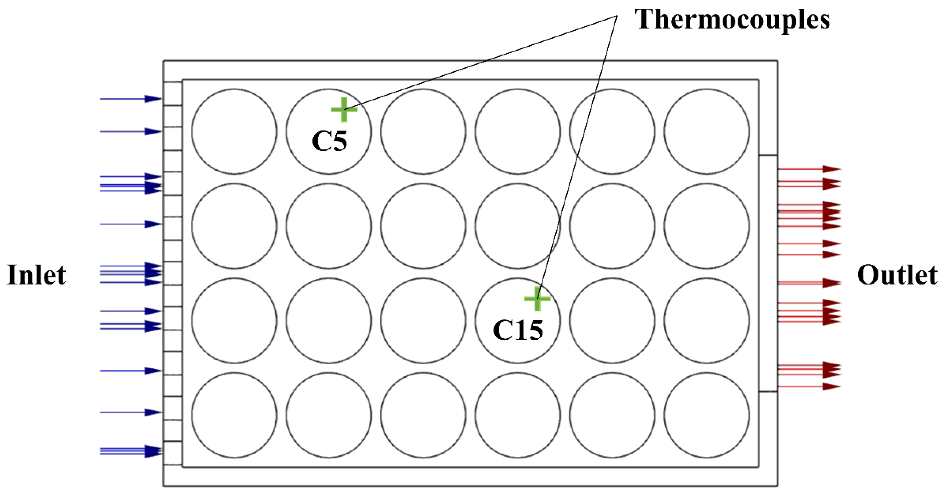
Typically, the cooling performance of the BTMS is evaluated by three index parameters: the maximum temperature, temperature difference and energy consumption [55]. To validate the numerical results of this work, the experimental data generated by Behi et al. [49] is chosen. The simulation configuration is the same as the experiment setup, which consists of a 24 cells battery pack, a PVC case, and a cooling fan, as shown in Figure 1. The testing point of the K-type thermocouple is designated at the specific position, which is the position of cell 5 (C5) and cell 15 (C15), as shown in Figure 2.
Under normal working conditions, the battery pack completed the discharge cycle with a 1.5 C discharge rate, which could be considered a heat source equal to 48,750 W·m−3. The air inlet velocity is 2 W·m−3 with coupled boundary conditions among air-battery and air-PVC case interfaces. The boundary walls are specified as adiabatic non-slip walls. The second-order upwind spatial discretization is applied for pressure, momentum, energy, turbulent kinetic energy and specific dissipation rate.
To achieve a credible CFD solution, mesh independence analysis is required to quantify the numerical errors and uncertainties. Based on the experimental layout, the geometry of the whole battery pack was built, and the computational region was mapped by an unstructured mesh, shown in Figure 3a. The maximum volume temperature and the surface weighted average temperature specified by C5 and C15 under various mesh element sizes to evaluate the mesh independence were illustrated in Figure 3b. Compared to the different grid size and element numbers, it is observed that the maximum volume temperature and the surface weighted average temperature of both cells stabilizes when the grid amount reaches 1.99 million. Hence, the medium element number of 1.99 million grids is applied for this battery pack simulation.
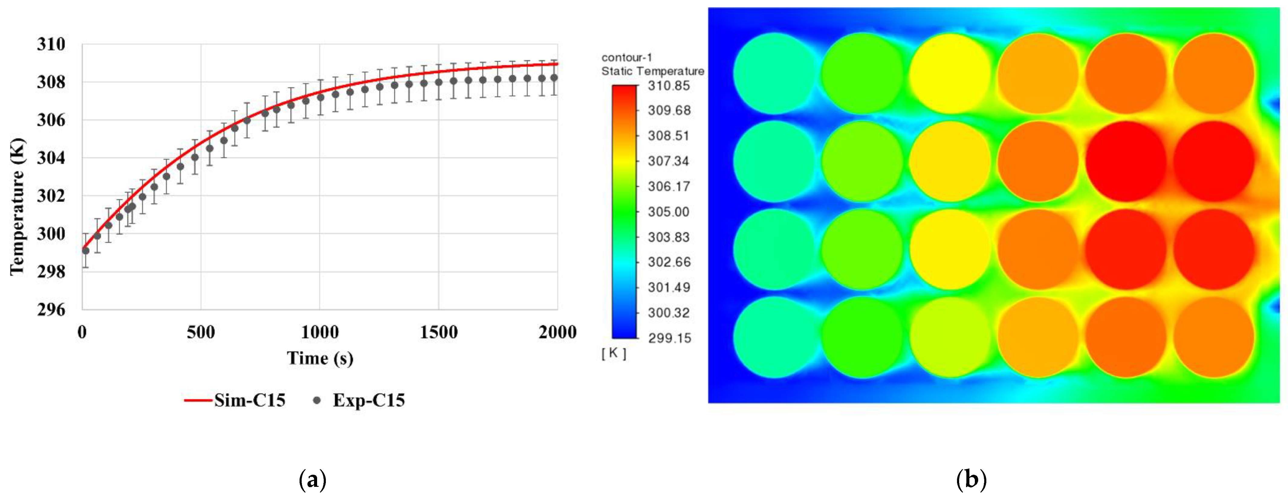
As shown in Figure 2, the experimental temperature data was collected and used to validate the numerical results. Validation of the CFD model means validating the numerical calculations by establishing a range of physical conditions obtained from the calculations and performing comparisons of the results from the CFD code with experiments that span the range of conditions. The comparison between the experimental data (black) and predicted temperature from the CFD model (red) is presented in Figure 4a, which demonstrates that the numerical results achieve an acceptable agreement with the experimental data. The relative error between the experimental and numerical results is approximately less than 0.3%. Thus, the error is acceptable, and the numerical model can capture the thermal behaviour and demonstrate proper prediction for the current setups. Figure 4b shows the temperature distribution of the cross-section plane for the whole computational domain.
3. Result and Discussion
3.1. Applied Extreme Heat to the Model
During the thermal runaway propagation, extra heat is generated due to complex exothermic reactions, and the temperature of the thermal runaway cell increased dramatically. This feather was captured experimentally by Lopez. et al. [31]. Based on the experimental data, we applied an in-house written user-defined function to replicate the temperature change of the thermal runaway cell. By using this code in the previously validated model, the current case successfully simulates the scenario with a cell experiencing thermal runaway. The case layout is the same as the pre-mentioned case, and an abnormal heat generation is applied in cell 6, shown in Figure 5a.
The heat propagation inside the battery pack was clearly presented in Figure 5b. Compared to Figure 4b, the added abnormal heat generation increased the maximum temperature with the value of 12 K. Additionally, the temperature difference also increased, which changed the original temperature distribution of the force-air cooling case.
In this case, the abnormal heat generation is applied, and the neighboring cell temperature is calculated and compared with the experimental data extracted from Lopez. et al. [31]. The comparison results between the numerical and experimental data are demonstrated in Figure 6, indicating a satisfactory agreement. The error of the maximum temperature for the neighboring cell is less than 1 K. Therefore, this case can be further expanded to analyze the heat transfer mechanism under the abnormal heat generation scenarios.
3.2. Different Abnormal Heat Generation Locations
Many previous studies focused on the design feature, such as channel configuration and coolant properties, to investigate the thermal behaviour of the battery pack and the cooling process. Different thermal runaway locations play an essential role in battery heat transfer and battery safety. Moreover, the heat propagation also affects the trigger of the thermal runaway for neighboring battery cells, which determines whether the abnormal heat generation will transfer to a severe battery fire or explosion. Experimental study on this point will cover an expensive expense, and it is hard to compare with various conditions. Hence, numerical investigation demonstrates an effective and efficient way to carry out the comparison study. It is safer and less polluted than heating or burning real battery cells and packs.
The current battery pack configuration from the top view of the battery pack consists of six cells in a row, the longitudinal direction along the forced-air cooling path, and four cells in a column, which is the transverse direction. Therefore, the battery pack can be treated as a symmetry set up along the air velocity direction. The total four rows can be divided into two rows near the outer case wall (Row 1 & 4), and another two in the middle (Row 2 & 3). Also, the top half with Row 1 & 2 can be mirrored to the bottom half with Row 3 & 4.
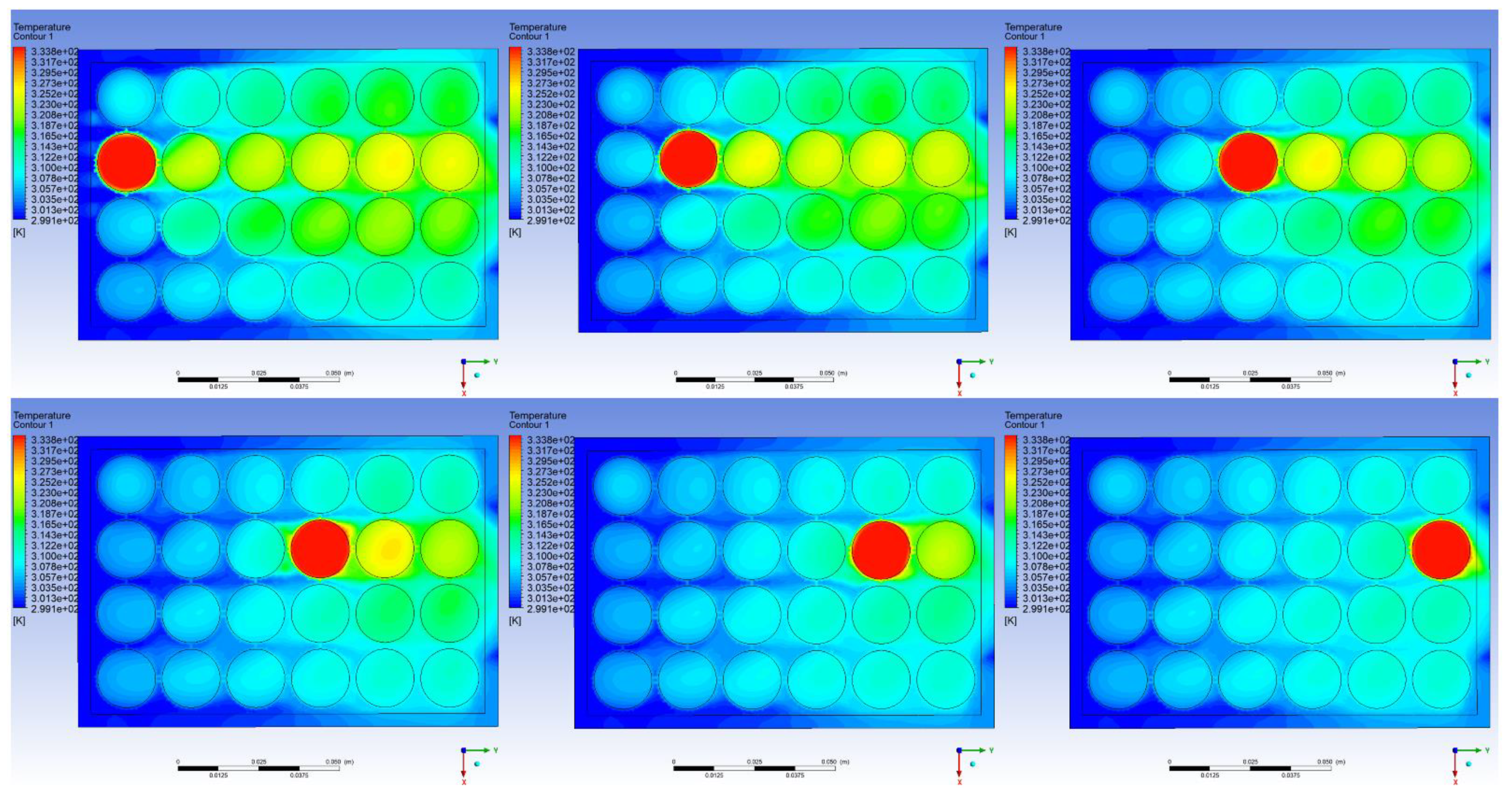
With the application of the in-house written user-defined function code, abnormal heat generation can be applied to the battery pack directly. The comparison of the various locations along the same row can be observed. For Row 2, the abnormal heat generation was applied from C2 (the nearest cell located to the air inlet) to C22 (the nearest cell located to the air outlet). The temperature distribution is shown in Figure 7. The applied abnormal heat generation was controlled as a thermal runaway in a single cell, but the heat did not trigger the thermal runaway of adjacent cells. The heat propagation has shown that the abnormal heat was transferred to the adjacent cell most along the longitudinal direction due to the forced-air cooling.
Due to the forced-air cooling, the abnormal heat was pushed to one dimension. For example, the case on the right of the top line showed that the cooling was efficient for the first two columns since the cooling air had not been heated up by the thermal runaway cell. Moreover, the location of the thermal runaway or abnormal heat generation affected the BTMS performance related to the maximum temperature and temperature difference. The thermal runaway cell not only heated the adjacent cells but also heated the cooling air, reducing the cooling performance of the downstream cells. From Figure 7, it is easy to find that the cells located upstream of the cell with abnormal heat generation were similar to the base case without extra heat. The temperature of the downstream cells was increased due to the abnormal heat generation, and the temperature difference was also increased.
According to the various locations of the thermal runaway cell, the maximum and minimum temperatures of C15 were compared and demonstrated in Figure 8. C15 is the cell in the same column as C14 and is also in Row 3. It can be concluded that the temperature of C15 was stabilized since the thermal runaway cell moved downstream of itself. Also, both the maximum and minimum temperatures increased by 9.1 K and 7.7 K, respectively, which illustrates that when abnormal heat is generated, or thermal runaway occurs, at the early stage, which is before the thermal runaway is triggered of adjacent cells, the increasing temperature is due to the fact that the cooling air was heated up and the cooling efficiency was reduced. Compared to cases C2 and C22, the maximum temperature was increased by 2.93%, and the minimum temperature was increased by 2.52%.
For Row 1, the thermal behaviour was similar to the Row 2 scenarios, shown in Figure 9. The demonstrated cases have abnormal heat generation at C5, C13 and C21. Considering the temperature change of C15, Row 2 (C6, C14, C22) has more influence on the temperature change than Row 1 (C5, C13, C21), and C15 is closer to Row 2. Additionally, comparing C5 case with C13 and C21, the corner temperature is higher, which is the same reason that the cooling air was heated up and the cooling performance is not enough for the corner cell.
4. Conclusions
This work developed a three-dimensional thermal model for the battery pack simulation by applying an in-house written code by ANSYS Fluent. The detailed temperature distribution of the whole battery pack was demonstrated under normal operating conditions and severe conditions, sucfigureh as thermal runaway or abnormal heat generation. After validating both scenarios, the comparison study of various extreme heat locations was carried out. The heat transfer mechanism inside the battery pack was investigated. The battery cell with abnormal heat generation not only increases the temperature of adjacent cells but also can heat the cooling air and leads to a relatively poor cooling performance. Take Row 2 cases as an example, the maximum temperature can be increased by 2.93%, and the cell temperature unbalancing was also increased.
The results highlight one significant advantage of the numerical analysis, which is the capability to simulate severe scenarios and ease of comparison with many different setups. The proposed model can be further applied to battery performance evaluation and optimization design. For future perspectives, more parameters can be involved and analyzed at the same time, including energy density [56] and charging cycle parameters. Moreover, these numerical results can be built as a dataset for coupling with machine learning techniques [57], such as artificial neural networks, to comprehensively enhance both the battery cell and the BTMS performance simultaneously, as well as improve the safety of the battery and energy storage system.
Author Contributions
Conceptualization, A.L. and A.C.Y.Y.; methodology, A.L. and W.W.; software, J.W.; validation, A.L. and J.W.; formal analysis, A.L. and C.S.L.; investigation, W.W.; resources, W.W. and J.W.; data curation, A.C.Y.Y.; writing—original draft preparation, A.L.; writing—review and editing, A.C.Y.Y. and S.K.; visualization, A.L.; supervision, G.H.Y.; project administration, A.C.Y.Y.; funding acquisition, G.H.Y. All authors have read and agreed to the published version of the manuscript.
Funding
This research was funded by the Australian Research Council (ARC Industrial Transformation Training Centre IC170100032) and the Australian Government Research Training Program Scholarship. The authors deeply appreciate all financial and technical supports.
Conflicts of Interest
The authors declare no conflict of interest.
References
- Kong, L.; Li, C.; Jiang, J.; Pecht, M.G. Li-ion battery fire hazards and safety strategies. Energies 2018, 11, 2191. [Google Scholar] [CrossRef] [Green Version]
- Wang, Q.; Mao, B.; Stoliarov, S.I.; Sun, J. A review of lithium ion battery failure mechanisms and fire prevention strategies. Prog. Energy Combust. Sci. 2019, 73, 95–131. [Google Scholar] [CrossRef]
- Sun, P.; Bisschop, R.; Niu, H.; Huang, X. A review of battery fires in electric vehicles. Fire Technol. 2020, 56, 1361–1410. [Google Scholar] [CrossRef]
- Yuen, A.C.Y.; Chen, T.B.Y.; Li, A.; de Cachinho Cordeiro, I.M.; Liu, L.; Liu, H.; Lo, A.L.P.; Chan, Q.N.; Yeoh, G.H. Evaluating the fire risk associated with cladding panels: An overview of fire incidents, policies, and future perspective in fire standards. Fire Mater. 2021, 45, 663–689. [Google Scholar] [CrossRef]
- Arora, S. Selection of thermal management system for modular battery packs of electric vehicles: A review of existing and emerging technologies. J. Power Sources 2018, 400, 621–640. [Google Scholar] [CrossRef]
- Yang, N.; Zhang, X.; Shang, B.; Li, G. Unbalanced discharging and aging due to temperature differences among the cells in a lithium-ion battery pack with parallel combination. J. Power Sources 2016, 306, 733–741. [Google Scholar] [CrossRef]
- Yuan, W.; Liang, D.; Chu, Y.; Wang, Q. Aging effect delays overcharge-induced thermal runaway of lithium-ion batteries. J. Loss Prev. Process Ind. 2022, 79, 104830. [Google Scholar] [CrossRef]
- Shahjalal, M.; Shams, T.; Islam, M.E.; Alam, W.; Modak, M.; Hossain, S.B.; Ramadesigan, V.; Ahmed, M.R.; Ahmed, H.; Iqbal, A. A review of thermal management for Li-ion batteries: Prospects, challenges, and issues. J. Energy Storage 2021, 39, 102518. [Google Scholar] [CrossRef]
- Goupil, V.; Gaya, C.; Boisard, A.; Robert, E. Effect of the heating rate on the degassing and combustion of cylindrical Li-Ion cells. Fire Saf. J. 2022, 1036, 13348. [Google Scholar] [CrossRef]
- Chen, M.; Liu, J.; Dongxu, O.; Cao, S.; Wang, Z.; Wang, J. A Simplified Analysis to Predict the Fire Hazard of Primary Lithium Battery. Appl. Sci. 2018, 8, 2329. [Google Scholar] [CrossRef]
- Huang, P.; Yao, C.; Mao, B.; Wang, Q.; Sun, J.; Bai, Z. The critical characteristics and transition process of lithium-ion battery thermal runaway. Energy 2020, 213, 119082. [Google Scholar] [CrossRef]
- Qin, P.; Sun, J.; Yang, X.; Wang, Q. Battery thermal management system based on the forced-air convection: A review. eTransportation 2021, 7, 100097. [Google Scholar] [CrossRef]
- Li, X.; Zhao, J.; Yuan, J.; Duan, J.; Liang, C. Simulation and analysis of air cooling configurations for a lithium-ion battery pack. J. Energy Storage 2021, 35, 102270. [Google Scholar] [CrossRef]
- Li, A.; Yuen, A.C.Y.; Wang, W.; Weng, J.; Yeoh, G.H. Numerical investigation on the thermal management of lithium-ion battery system and cooling effect optimization. Appl. Therm. Eng. 2022, 215, 118966. [Google Scholar] [CrossRef]
- Li, A.; Yuen, A.C.Y.; Wang, W.; Chen, T.B.Y.; Lai, C.S.; Yang, W.; Wu, W.; Chan, Q.N.; Kook, S.; Yeoh, G.H. Integration of Computational Fluid Dynamics and Artificial Neural Network for Optimization Design of Battery Thermal Management System. Batteries 2022, 8, 69. [Google Scholar] [CrossRef]
- Deng, Y.; Feng, C.; Jiaqiang, E.; Zhu, H.; Chen, J.; Wen, M.; Yin, H. Effects of different coolants and cooling strategies on the cooling performance of the power lithium ion battery system: A review. Appl. Therm. Eng. 2018, 142, 10–29. [Google Scholar] [CrossRef]
- Wang, Y.; Zhang, G.; Yang, X. Optimization of liquid cooling technology for cylindrical power battery module. Appl. Therm. Eng. 2019, 162, 114200. [Google Scholar] [CrossRef]
- Yang, Y.; Li, W.; Xu, X.; Tong, G. Heat dissipation analysis of different flow path for parallel liquid cooling battery thermal management system. Int. J. Energy Res. 2020, 44, 5165–5176. [Google Scholar] [CrossRef]
- Liang, J.; Gan, Y.; Li, Y. Investigation on the thermal performance of a battery thermal management system using heat pipe under different ambient temperatures. Energy Convers. Manag. 2018, 155, 1–9. [Google Scholar] [CrossRef]
- Wang, J.; Gan, Y.; Liang, J.; Tan, M.; Li, Y. Sensitivity analysis of factors influencing a heat pipe-based thermal management system for a battery module with cylindrical cells. Appl. Therm. Eng. 2019, 151, 475–485. [Google Scholar] [CrossRef]
- Jouhara, H.; Serey, N.; Khordehgah, N.; Bennett, R.; Almahmoud, S.; Lester, S.P. Investigation, development and experimental analyses of a heat pipe based battery thermal management system. Int. J. 2020, 1, 100004. [Google Scholar] [CrossRef]
- Weng, J.; Yang, X.; Zhang, G.; Ouyang, D.; Chen, M.; Wang, J. Optimization of the detailed factors in a phase-change-material module for battery thermal management. Int. J. Heat Mass Transf. 2019, 138, 126–134. [Google Scholar] [CrossRef]
- Weng, J.; Ouyang, D.; Yang, X.; Chen, M.; Zhang, G.; Wang, J. Optimization of the internal fin in a phase-change-material module for battery thermal management. Appl. Therm. Eng. 2020, 167, 114698. [Google Scholar] [CrossRef]
- Wang, J.; Huang, Q.; Li, X.; Zhang, G.; Wang, C. Experimental and numerical simulation investigation on the battery thermal management performance using silicone coupled with phase change material. J. Energy Storage 2021, 40, 102810. [Google Scholar] [CrossRef]
- Weng, J.; Huang, Q.; Li, X.; Zhang, G.; Ouyang, D.; Chen, M.; Yuen, A.C.Y.; Li, A.; Lee, E.W.M.; Yang, W. Safety Issue on PCM-based Battery Thermal Management: Material Thermal Stability and System Hazard Mitigation. Energy Storage Mater. 2022, 53, 580–612. [Google Scholar] [CrossRef]
- Yuan, X.; Zhou, X.; Pan, Y.; Kosonen, R.; Cai, H.; Gao, Y.; Wang, Y. Phase change cooling in data centers: A review. Energy Build. 2021, 236, 110764. [Google Scholar] [CrossRef]
- Song, L.; Zhang, H.; Yang, C. Thermal analysis of conjugated cooling configurations using phase change material and liquid cooling techniques for a battery module. Int. J. Heat Mass Transf. 2019, 133, 827–841. [Google Scholar] [CrossRef]
- Li, J.; Zhang, H. Thermal characteristics of power battery module with composite phase change material and external liquid cooling. Int. J. Heat Mass Transf. 2020, 156, 119820. [Google Scholar] [CrossRef]
- Chen, K.; Hou, J.; Song, M.; Wang, S.; Wu, W.; Zhang, Y. Design of battery thermal management system based on phase change material and heat pipe. Appl. Therm. Eng. 2021, 188, 116665. [Google Scholar] [CrossRef]
- Weng, J.; Xiao, C.; Yang, X.; Ouyang, D.; Chen, M.; Zhang, G.; Waiming, E.L.; Yuen, R.K.K.; Wang, J. An energy-saving battery thermal management strategy coupling tubular phase-change-material with dynamic liquid cooling under different ambient temperatures. Renew. Energy 2022, 195, 918–930. [Google Scholar] [CrossRef]
- Lopez, C.F.; Jeevarajan, J.A.; Mukherjee, P.P. Experimental analysis of thermal runaway and propagation in lithium-ion battery modules. J. Electrochem. Soc. 2015, 162, A1905. [Google Scholar] [CrossRef]
- Immonen, E.; Hurri, J. Incremental thermo-electric CFD modeling of a high-energy Lithium-Titanate Oxide battery cell in different temperatures: A comparative study. Appl. Therm. Eng. 2021, 197, 117260. [Google Scholar] [CrossRef]
- Estevez, M.A.P.; Calligaro, S.; Bottesi, O.; Caligiuri, C.; Renzi, M. An electro-thermal model and its electrical parameters estimation procedure in a lithium-ion battery cell. Energy 2021, 234, 121296. [Google Scholar] [CrossRef]
- Mesbahi, T.; Sugrañes, R.B.; Bakri, R.; Bartholomeüs, P. Coupled electro-thermal modeling of lithium-ion batteries for electric vehicle application. J. Energy Storage 2021, 35, 102260. [Google Scholar] [CrossRef]
- Li, A.; Yuen, A.C.Y.; Wang, W.; de Cachinho Cordeiro, I.M.; Wang, C.; Chen, T.B.Y.; Zhang, J.; Chan, Q.N.; Yeoh, G.H. A review on lithium-ion battery separators towards enhanced safety performances and modelling approaches. Molecules 2021, 26, 478. [Google Scholar] [CrossRef]
- Cui, X.; Chen, S.; Xiao, M.; Li, W. A computational fluid dynamics coupled multi-objective optimization framework for thermal system design for Li-ion batteries with metal separators. J. Electrochem. Energy Convers. Storage 2021, 18, 030903. [Google Scholar] [CrossRef]
- Shiea, M.; Querio, A.; Buffo, A.; Boccardo, G.; Marchisio, D. CFD-PBE modelling of continuous Ni-Mn-Co hydroxide co-precipitation for Li-ion batteries. Chem. Eng. Res. Des. 2022, 177, 461–472. [Google Scholar] [CrossRef]
- Liu, H.; Wang, C.; de Cachinho Cordeiro, I.M.; Yuen, A.C.Y.; Chen, Q.; Chan, Q.N.; Kook, S.; Yeoh, G.H. Critical assessment on operating water droplet sizes for fire sprinkler and water mist systems. J. Build. Eng. 2020, 28, 100999. [Google Scholar] [CrossRef]
- Yuen, A.C.Y.; Chen, T.B.Y.; de Cachinho Cordero, I.M.; Liu, H.; Li, A.; Yang, W.; Cheung, S.C.P.; Chan, Q.N.; Kook, S.; Yeoh, G.H. Developing a solid decomposition kinetics extraction framework for detailed chemistry pyrolysis and combustion modelling of building polymer composites. J. Anal. Appl. Pyrolysis 2022, 163, 105500. [Google Scholar] [CrossRef]
- Yuen, A.C.Y.; de Cachinho Cordeiro, I.M.; Chen, T.B.Y.; Chen, Q.; Liu, H.; Yeoh, G.H. Multiphase CFD modelling for enclosure fires—A review on past studies and future perspectives. Exp. Comput. Multiph. Flow 2021, 4, 1–25. [Google Scholar] [CrossRef]
- Sun, W.; Liu, W.-D.; Liu, Q.; Chen, Z.-G. Advances in thermoelectric devices for localized cooling. Chem. Eng. J. 2022, 450, 138389. [Google Scholar] [CrossRef]
- Jishnu, A.; Garg, A.; Shaosen, S.; Su, Y.; Panigrahi, B.K. A novel procedure combining computational fluid dynamics and evolutionary approach to minimize parasitic power loss in air cooling of Li-ion battery for thermal management system design. Energy Storage 2021, 3, e210. [Google Scholar] [CrossRef]
- Falcone, M.; de Volo, E.P.B.; Hellany, A.; Rossi, C.; Pulvirenti, B. Lithium-Ion Battery Thermal Management Systems: A Survey and New CFD Results. Batteries 2021, 7, 86. [Google Scholar] [CrossRef]
- Jindal, P.; Sharma, P.; Kundu, M.; Singh, S.; Shukla, D.K.; Pawar, V.J.; Wei, Y.; Breedon, P. Computational Fluid Dynamics (CFD) analysis of Graphene Nanoplatelets for the cooling of a multiple tier Li-ion battery pack. Therm. Sci. Eng. Prog. 2022, 31, 101282. [Google Scholar] [CrossRef]
- Tang, Z.; Song, A.; Wang, S.; Cheng, J.; Tao, C. Numerical Analysis of Heat Transfer Mechanism of Thermal Runaway Propagation for Cylindrical Lithium-ion Cells in Battery Module. Energies 2020, 13, 1010. [Google Scholar] [CrossRef] [Green Version]
- Chen, W.; Hou, S.; Shi, J.; Han, P.; Liu, B.; Wu, B.; Lin, X. Numerical Analysis of Novel Air-Based Li-Ion Battery Thermal Management. Batteries 2022, 8, 128. [Google Scholar] [CrossRef]
- Yang, W.; Wang, Y.; Guo, F.; Bai, Y.; Liu, X. Optimization study of air-cooled stagger-arranged battery pack with reverse-layered airflow. J. Energy Storage 2022, 55, 105524. [Google Scholar] [CrossRef]
- Zhai, H.; Li, H.; Ping, P.; Huang, Z.; Wang, Q. An experimental-based Domino prediction model of thermal runaway propagation in 18,650 lithium-ion battery modules. Int. J. Heat Mass Transf. 2021, 181, 122024. [Google Scholar] [CrossRef]
- Behi, H.; Karimi, D.; Behi, M.; Ghanbarpour, M.; Jaguemont, J.; Sokkeh, M.A.; Gandoman, F.H.; Berecibar, M.; van Mierlo, J. A new concept of thermal management system in Li-ion battery using air cooling and heat pipe for electric vehicles. Appl. Therm. Eng. 2020, 174, 115280. [Google Scholar] [CrossRef]
- Yuen, A.C.Y.; Chen, T.B.Y.; Wang, C.; Wei, W.; Kabir, I.; Vargas, J.B.; Chan, Q.N.; Kook, S.; Yeoh, G.H. Utilising genetic algorithm to optimise pyrolysis kinetics for fire modelling and characterisation of chitosan/graphene oxide polyurethane composites. Compos. Part B Eng. 2020, 182, 107619. [Google Scholar] [CrossRef]
- Sharma, A.R.; Sai, C.S.; Kumar, A.; Reddy, R.V.J.; Danyharsha, D.; Jilte, R. Three-dimensional CFD study on heat dissipation in cylindrical lithium-ion battery module. Mater. Today Proc. 2021, 46, 10964–10968. [Google Scholar] [CrossRef]
- Yuen, A.C.Y.; Yeoh, G.H. Numerical simulation of an enclosure fire in a large test hall. Comput. Therm. Sci. Int. J. 2013, 5, 459–471. [Google Scholar] [CrossRef]
- De Cachinho Cordeiro, I.M.; Liu, H.; Yuen, A.C.Y.; Chen, T.B.Y.; Li, A.; Cao, R.F.; Yeoh, G.H. Numerical investigation of expandable graphite suppression on metal-based fire. Heat Mass Transf. 2022, 58, 65–81. [Google Scholar] [CrossRef]
- Li, W.; Garg, A.; Wang, N.; Gao, L.; le Phung, M.L.; Tran, V.M. Computational Fluid Dynamics-Based Numerical Analysis for Studying the Effect of Mini-Channel Cooling Plate, Flow Characteristics, and Battery Arrangement for Cylindrical Lithium-Ion Battery Pack. J. Electrochem. Energy Convers. Storage 2022, 19, 041003. [Google Scholar] [CrossRef]
- Wang, Y.; Liu, B.; Han, P.; Hao, C.; Li, S.; You, Z.; Wang, M. Optimization of an air-based thermal management system for lithium-ion battery packs. J. Energy Storage 2021, 44, 103314. [Google Scholar] [CrossRef]
- Bi, Z.; Guo, X. Solidification for solid-state lithium batteries with high energy density and long cycle life. Energy Mater. 2022, 2, 200011. [Google Scholar] [CrossRef]
- Deng, Q.; Lin, B. Automated machine learning structure-composition-property relationships of perovskite materials for energy conversion and storage. Energy Mater. 2021, 1, 100006. [Google Scholar] [CrossRef]
Figure 1.
Schematic figure of the battery pack with 24 18,650 cells.

Figure 2.
Schematic figure of thermocouple testing point.

Figure 3.
(a) Schematic of the computational domain and mesh; (b) Mesh independence analysis.

Figure 4.
(a) Numerical model validation, the error bar is 0.3%; (b) Temperature distribution in the cross-section plane.
Figure 4.
(a) Numerical model validation, the error bar is 0.3%; (b) Temperature distribution in the cross-section plane.

Figure 5.
(a) Schematic figure of the battery with a thermal runaway cell; (b) Temperature distribution in the cross-section plane under this scenario.
Figure 5.
(a) Schematic figure of the battery with a thermal runaway cell; (b) Temperature distribution in the cross-section plane under this scenario.

Figure 6.
Comparison between the numerical and experimental data for a temperature change of the neighboring cell. The error bar is 2.5%.
Figure 6.
Comparison between the numerical and experimental data for a temperature change of the neighboring cell. The error bar is 2.5%.

Figure 7.
Comparison of the temperature distributions among the applied abnormal heat generation on different cells in Row 2.
Figure 7.
Comparison of the temperature distributions among the applied abnormal heat generation on different cells in Row 2.

Figure 8.
Temperature changes of cell 15 among the applied abnormal heat generation on different cells in Row 2.
Figure 8.
Temperature changes of cell 15 among the applied abnormal heat generation on different cells in Row 2.

Figure 9.
Comparison of the temperature distributions among the applied abnormal heat generation on different cells in Row 1.
Figure 9.
Comparison of the temperature distributions among the applied abnormal heat generation on different cells in Row 1.


Table 1.
Parameters and properties of the battery cell, ventilation fan and outer case.
| Parameters of Battery Cell | Parameters of Ventilation Fan | Parameters of Outer Case | |||
|---|---|---|---|---|---|
| Specific heat capacity | 1200 J·kg−1K−1 | Outlet diameter | 50 mm | Specific heat capacity | 600 J·kg−1K−1 |
| Density | 2722 kg·m−3 | Inlet air temperature | 299.15 K | Density | 100 kg·m−3 |
| Anisotropic thermal conductivities | kr = 0.2 W·m−1K−1, kz = 37.6 W·m−1K−1 | Pack size (length × width × height) | 130 mm × 90 mm × 70 mm | Thermal conductivities | 0.1 W·m−1K−1 |
Publisher’s Note: MDPI stays neutral with regard to jurisdictional claims in published maps and institutional affiliations. |
© 2022 by the authors. Licensee MDPI, Basel, Switzerland. This article is an open access article distributed under the terms and conditions of the Creative Commons Attribution (CC BY) license (https://creativecommons.org/licenses/by/4.0/).
Share and Cite
MDPI and ACS Style
Li, A.; Yuen, A.C.Y.; Wang, W.; Weng, J.; Lai, C.S.; Kook, S.; Yeoh, G.H. Thermal Propagation Modelling of Abnormal Heat Generation in Various Battery Cell Locations. Batteries 2022, 8, 216. https://doi.org/10.3390/batteries8110216
AMA Style
Li A, Yuen ACY, Wang W, Weng J, Lai CS, Kook S, Yeoh GH. Thermal Propagation Modelling of Abnormal Heat Generation in Various Battery Cell Locations. Batteries. 2022; 8(11):216. https://doi.org/10.3390/batteries8110216
Chicago/Turabian StyleLi, Ao, Anthony Chun Yin Yuen, Wei Wang, Jingwen Weng, Chun Sing Lai, Sanghoon Kook, and Guan Heng Yeoh. 2022. "Thermal Propagation Modelling of Abnormal Heat Generation in Various Battery Cell Locations" Batteries 8, no. 11: 216. https://doi.org/10.3390/batteries8110216
Note that from the first issue of 2016, this journal uses article numbers instead of page numbers. See further details here.