
Phenazine-Based Compound as a Universal Water-Soluble Anolyte Material for the Redox Flow Batteries

1
Skolkovo Institute of Science and Technology, Bolshoy Boulevard 30, bld. 1, 121205 Moscow, Russia
2
Federal Research Center of Problems of Chemical Physics and Medicinal Chemistry of Russian Academy of Sciences, Semenov Prospect 1, Moscow Region, 142432 Chernogolovka, Russia
3
Department of Chemistry and Biochemistry, University of South Carolina, 631 Sumter Street, Columbia, SC 29208, USA
4
Chemistry Department, Lomonosov Moscow State University, Leninskiye Gory 1/3, 119991 Moscow, Russia
*
Author to whom correspondence should be addressed.
Batteries 2022, 8(12), 288; https://doi.org/10.3390/batteries8120288
Submission received: 31 October 2022
/
Revised: 21 November 2022
/
Accepted: 8 December 2022
/
Published: 14 December 2022
(This article belongs to the Section Battery Materials and Interfaces: Anode, Cathode, Separators and Electrolytes or Others)
Abstract
:Aqueous organic redox flow batteries (AORFBs) are emerging energy storage technologies due to their high availability, low cost of organic compounds, and the use of eco-friendly water-based supporting electrolytes. In the present work, we demonstrate a unique phenazine-based material that shows redox reversibility in neutral, basic, and acidic conditions with the redox potentials of −0.85 V (1.0 M KOH), −0.67 V (1.0 M NaCl), −0.26 V, and 0.05 V (1.0 M H2SO4) vs. the Ag/AgCl reference electrode and two-electron transfer process at all pH values. High solubility of the phenazine compound in water-based electrolytes up to 1.3 M is achieved by introducing quaternary amonium-based substituents, leading to the outstanding theoretical volumetric capacity of 70 Ah L−1. Laboratory redox flow batteries in neutral and acidic electrolytes presented >100 cycles of stable operation with a capacity loss of 0.25 mAh L−1 and 1.29 mAh L−1 per cycle, respectively. The obtained results demonstrate a material with the potential for not only fundamental understanding but also the practical application of AORFBs in the development of new-generation energy storage technologies.
1. Introduction
The rapid increase in the contribution of renewable energy sources, for example, solar, wind, or geothermal power, requires the design and development of large-scale energy storage systems that are able to buffer and distribute electricity from renewables to the grid [1,2]. According to the Energy Storage Grand Challenge Market Report, the energy storage market is estimated to grow to 2.5–4 TW·h by 2030, which is approximately 3 to 5 times higher compared to the current 800 GW·h market [1]. The existing stationary energy capacities are mostly presented by pumped-storage hydropower and compressed-air energy storage, while the new projects are mainly based on lithium-ion batteries. However, the lithium content is limited for future demand for all high-capacity energy storage, even in the short-to-medium perspective [3].
These shortcomings could be overcome in post-lithium electrochemical energy storage technology, for example, in redox flow batteries (RFBs) [4,5,6]. Redox flow batteries are considered a safe alternative compared to lithium-ion-based analogs and are more promising for applications where long-duration storage is required. However, inorganic RFB technology is hampered due to the economic reasons (for example, the price of vanadium was varied 10 times over the last 10 years [7]), instability of inexpensive Fe-base electrolytes [8], crossover issue, and the use of unsafe redox-active materials (such as heavy metals (vanadium) or other toxic materials (liquid bromine)). In this regard, interest in organic redox-active molecules is rapidly increasing [9,10,11].
Organic chemistry provides great opportunities to design molecules with the desired properties. Thus, to achieve the high redox stability of the compounds, different core structures possessing donor blocks [12,13,14,15], acceptor blocks [16,17,18,19], and solubilizing ligands [20,21,22,23,24] could be used. To suppress the crossover of the redox species, core structures could be combined into oligomers [25,26,27,28,29,30] or complemented by charged ligands [15,31,32]. Several classes of the compounds were already found to be promising redox-active materials for the RFBs, including quinones and hydroquinones [29,33,34,35], viologens [15,36,37,38,39,40], TEMPO-based molecules [32,41,42,43,44,45], alloxazines [46,47,48], and phenazines [14,49,50,51,52,53].
Quinones and phenazines are considered the most well-known and prospective compounds among the anolyte materials. Although anthraquinones are able to possess very high stability in acetic media, the redox potentials of the anthraquinones are significantly high; for example, the redox potential of the anthraquinone-2,6-disulfonic acid is only −0.2 V vs. Ag/AgCl [29]. The introduction of the donor ethylene glycol chains and application of neutral solutions lead to the potential shift to the more negative region up to −0.64 V vs. Ag/AgCl [33]. Phenazine-based compounds are able to possess lower reduction potentials up to −1.1 V vs. Ag/AgCl [49] in basic conditions. Thus, phenazine could be named as one of the most prospective core structures for the creation of the organic anolytes.
Proper modification of the core structures allows the acquiring of promising compounds with predetermined behavior. Thus, the design of the novel phenazine-based compound with ethylene glycol substituents allowed us to obtain and investigate the first redox-active phenazine derivative with high solubility in organic solvents [54]. However, phenazines could also be used as promising anolytes in AORFBs (Supplementary Materials Table S1). For example, Yun Yu Lai et al. demonstrated high redox stability of the amino-substituted phenazine-based compounds; however, the low solubility, ranging from 0.10 to 0.34 M, limits their practical applicability in commercial cells [14]. Hollas et al. [50] and Wang et al. [51] reported the introduction of the -OH functional group(s) to the phenazine core, leading to a significant increase in the solubility of the compound in alkaline solutions (e.g., 1.7 M in 1.0 M KOH). The introduction of the -COOH group allowed for an increase in both solubility and redox stability, yet these compounds in basic solutions convert to the anionic form, resulting in a high crossover of active compounds through the ion-exchange membrane [49,52].
In the present work, we report the rational design of a highly water-soluble compound, 3,3’-(phenazine-2,3-diylbis(oxy))bis(N,N,N-trimethylpropan-1-aminium) (M1), based on phenazine modification by the introduction of substituents containing quaternary ammonium bases, which were successfully applied for the modification of different core structures in previously reported research work [15,31,32,55,56,57]. Such modification of the phenazine molecule allows for the creation of anolyte material as a ionic positive-charge form (cationic phenazine-based molecule and Br− counterions). Such a structure of the compound affords the suppression of the crossover between the positively charged anolyte and positively charged catholyte in the cell, resulting in more stable battery cycling.
Herein, the design and synthesis of the phenazine-based compound M1 are proposed. For the proper evaluation of the electrochemical properties of M1, cyclic voltammetry (CV) measurements were performed in a wide range of pH, revealing the high stability of two-electron reduction of M1 in acidic, neutral, and base conditions. This allowed for the creation and cycling of the RFBs with the M1 anolyte and 1.0 M H2SO4, NaCl, and KOH supporting electrolytes (SEs). Hence, in this work, we presented for the first time the possibility of using one compound for RFBs with any pH of the SE.
2. Materials and Methods
2.1. Synthesis and Characterization
All applied reagents and solvents were obtained from Sigma-Aldrich or Acros Organics and used as received or purified according to standard procedures. Applied membranes were purchased from Fuel Cell Store. The 1H and 13C NMR spectra were measured by using Bruker AVANCE III 500 instrument. Chemical analysis was performed by using a Vario Microcube instrument. High-performance liquid chromatographs were obtained by using a Shimadzu 20A chromatograph with Orbit 100 C18 (5 μm particle size, 0.25 m × 4.6 mm, MZ-Analyentechnik GmbH, Mainz, Germany) analytical column.
2.2. Synthesis of Phenazine-2,3-diol (1) [54]
O-diaminobenzene (0.85 g, 7.8 mmol, 1.1 eq.) and 2,5-dihydroxy-p-benzoquinone (1.0 g, 7.1 mmol, 1.1 eq.) mixture was refluxed in water for 12 h. The solution was then stirred for 12 h at room temperature. The obtained precipitate was isolated by filtration, affording 1.2 g of the target product 1 (78% yield).
1H NMR (DMSO-d6, 500 MHz, δ): 11.02 (OH, br s, 2H); 8.11 (s, 2H); 7.79 (s, 2H); 7.35 (s, 2H).
2.3. Synthesis of 3,3’-(Phenazine-2,3-diylbis(oxy))bis(N,N,N-trimethylpropan-1-aminium) bromide (M1)
Compound 1 (5.0 g, 23.5 mmol) and (3-bromopropyl)-trimethylammonium bromide (25.0 g, 94 mmol, 4 eq.) were dissolved in absolute N,N-dimethylformamide (150 mL), and potassium carbonate (16.3 g, 117.5 mmol, 5 eq.) was added under argon. The mixture was stirred at 80 °C for 12 h. The solvent was removed in vacuo, and the residue was re-dissolved in 100 mL of 2-propanol. The solution was filtered through a pad of silica (5 cm deep). The solvent was evaporated to 30 mL under reduced pressure and cooled down to 10 °C in an ice bath. The product was precipitated as pale-yellow powder, filtered, and dried in air. The yield of M1 was 30%.
1H NMR (DMSO-d6, 500 MHz, δ): 8.07 (dd, 2H); 7.82 (dd, 2H); 7.37 (s, 2H); 4.29 (t, 4H); 4.02 (m, 4H); 3.12 (s, 18H); 3.91 (m, 4H).
13C NMR (CDCl3, 126 MHz, δ): 153.98; 141.78; 130.73; 128.96; 106.37; 66.90; 63.90; 53.48; 23.06.
Chemical analysis (%) for C24H36Br2N4O2: C, 50.36; H, 6.34; Br, 27.92; N, 9.79; O, 5.59; found C, 46.82; H, 6.126; N, 8.94.
2.4. Solubility Experiments
The deionized water or 1.0 M background electrolyte solution (NaCl, H2SO4, or KOH) was added drop by drop to 20 mg (0.035 mmol) of M1 powders until the full dissolution of the powders. The solvent and solution weights were used for the calculation of the M1 concentration.
2.5. Solutions pH Measurements
Measurements of the pH were performed by using pH/mV/°C meter HI 83141 and pH electrode HI 1230D by HANNA instruments (Woonsocket, RI, USA).
2.6. Melting Point Determination
Thermoanalytical measurements were performed by Netzsch DSC 214 Polyma instrument under N2, with a heating rate of 10 °C min−1.
2.7. Density Functional Theory Calculations
In order to calculate the formal reduction potentials, a previously reported procedure was used [58]. Specifically, density functional theory (DFT) calculations were accomplished by utilizing a Gaussian16 (revision C.01) Software Package [59] with an ultrafine grid in three computations:
(i) Geometrical optimization;
(ii) Frequency check;
(iii) Single-point energy calculation and NBO analysis22 with a more accurate basis step.
The geometry optimization in the gas phase was carried out with the M06-2X/6-31 + g(d,p) level of theory and a tight convergence criterion. The minimized structures were confirmed with a frequency check, and the gas-phase optimized geometry structures were utilized for the calculation in this work. Following this structure optimization, we performed a single-point energy calculation, using the M06-2X/jun-cc-pvtz level of theory for more accurate free energies of the ground state for the phenazine molecule. Finally, a single-point calculation for the phenazine was performed at the same level of theory (M06-2x/jun-cc-pvtz) in water via a continuum solvation model based on the solvent model “density” (SDM) (i.e., the quantum mechanical electron density of the molecule). In all computations, Gaussian defaults were used unless otherwise specified.
2.8. CV Measurements
Cyclic voltammograms were recorded in a three-electrode cell with glassy carbon working electrode (WE) (d = 5 mm), Ag/AgCl reference electrode (RE), and carbon counter electrode (CE) under an argon atmosphere. In the case of working in high-pH regions, the Hg/HgO RE was used instead of Ag/AgCl. The calibration of Hg/HgO electrode vs. Ag/AgCl electrode is presented in Supplementary Figure S11. Before the measurements WE and CE were polished with ¼ 𝜇𝑚 diamond suspension. CVs of the supporting electrolytes were obtained before the measurements (Supplementary Figure S8). Measurements were performed on Metrohm Autolab potentiostat (Metrohm Autolab, Utrecht, The Netherlands).
2.9. RDE Experiments
Rotating disk electrode measurements were performed by using 15.0 mM active substance and 0.5 M SE (KOH, NaCl, or H2SO4) concentrations based on deionized water. A glassy carbon working electrode (d = 5 mm) was rotated by a Metrohm rotor (Metrohm Autolab) in a gas-tight cell, and the rotation speed varied from 300 to 2100 rpm; RE—Ag/AgCl; CE—carbon electrode. Current-potential curves were recorded on Metrohm Autolab potentiostat.
Diffusion coefficients from the rotation disk electrode measurements were calculated according to the Levich equation for rotation disk electrode measurements [60]:
where IL is the limiting current (A), n is the number of transferred electrons, F is the Faraday constant (C mol−1), A is electrode area (cm2), D is the diffusion coefficient (cm2 s−1), ω is the angular rotation rate of the electrode (rad s−1), ν is the kinematic viscosity (cm2 s−1), C is the redox-active material concentration (mol cm−3).
IL = 0.620 × n × F × A × D2/3 × ω1/2 × ν−1/6 × C
The standard electrochemical rate constant, k0, was measured by the use of the Koutecký-Levich method. The current responses at overpotentials in the range of 0 to 0.2 V were used to construct a Koutecky-Levich plot. At each overpotential value the data was linearly extrapolated to the intercept to give the kinetically-limited current ik. A plot of the logarithm of ik against overpotential provided linear relationship which was extrapolated to zero overpotential to give the intercept. The intercept can was related to the electrochemical rate constant and transfer coefficient:
where k0 is kinetic constant (cm s−1), R is universal gas constant (J⋅K−1 mol−1), T is room temperature (K).
Intercept = log (n × F × A × k0 × C) slope = β × F/(R × T) α = 1 − β
2.10. Impedance Measurements
Impedance curves were obtained on a Biologic VMP3 (BioLogic, Seyssinet-Pariset, France) potentiostat in the 1 MHz–0.01 Hz frequency range and 10 mV amplitude.
2.11. Membrane Pretreatment
Nafion 117 membrane was prepared by the following procedure: boiled in 3 wt.% H2O2 in deionized water; after that, boiled in 1 M H2SO4; and finally boiled in deionized water for 1 h, according to the procedure recommended by Bo Jiang et al. in a detailed study [61]. After that, Nafion 117 membrane was conditioned in 1.0 M NaCl solutions for 24 h at room temperature.
Anion-exchanged membranes (Neosepta AHA and Fumasept FAA-3-PK 130) were conditioned in 1.0 M NaCl, 1.0 H2SO4, or 1.0 M KOH solutions for 24 h at room temperature.
2.12. Membrane Conductivity Measurements
For the membrane conductivity measurements, the cell with 2 compartments (into each compartment carbon working electrode was placed) with a membrane between them were used. Concentrations of the supporting electrolytes were 1.0 M of NaCl, KOH, or H2SO4 in deionized water. The distance between the electrodes was 4 cm, and the membrane area was d = 1 cm.
2.13. H-Cell Tests
A small volume h-cell consisted of the following components: tanks with catholyte and anolyte, electrodes (graphite felt, electrodes size 0.5 cm × 1.0 × 0.3 cm), platinum wire current collectors (d = 0.5 mm), 2 stirring bars, and membrane (0.863 cm2) (Supplementary Figure S6).
Used electrolytes were based on 1M NaCl, 1M H2SO4, or 1M KOH solutions. The volume of electrolytes was 5 mL. Galvanostatic or galvanostatic + potentiostatic cycling was performed by using Biologic VMP3 (BioLogic, Seyssinet-Pariset, France) or Ellins (Electrochemical Instruments, Chernogolovka, Russia) potentiostat. For the charge–discharge stability tests, h-cells were charged till the upper cutoff and then discharged at the same current; after that, the cycle was repeated 50 or more times.
2.14. Redox Flow Battery Tests
A small volume RFB was used (Supplementary Figure S7). Peristaltic pump Heildolf Hei-Flow Precision 0.1 Multi was used to create the flow of electrolytes (flow rate 10 mL min−1).
The applied electrolytes were based on 1.0 M NaCl or H2SO4 water solutions. The volumes of electrolytes were 10 mL on each side. Galvanostatic or galvanostatic + potentiostatic cycling was performed by using Biologic VMP3 (BioLogic, Seyssinet-Pariset, France) or Ellins (Electrochemical Instruments, Chernogolovka, Russia) potentiostat under air conditions.
3. Results and Discussion
3.1. Synthesis and Characterization of M1
Phenazine modification was carried out by introducing substituents containing quaternary ammonium bases (Figure 1a). The designed compound M1 was synthesized in two steps from commercially available precursors. First, the condensation reaction of 2,5-dihydroxy-1,4-benzoquinone and o-phenylenediamine in water produced phenazine-2,3-diol (1). Then the reaction of the obtained precursor 1 with (3-bromopropyl)-trimethylammonium bromide in N,N-dimethylformamide (DMF) and potassium carbonate as the base resulted in compound M1.
M1 was characterized by NMR spectroscopy, high-performance liquid chromatography, and chemical analysis (NMR spectrum is presented in Figure 1c and Supplementary Figure S1–S4). Compound M1 was found to be a solid compound at ambient temperature (25 °C), with the melting point of 273 °C (Supplementary Figure S5). The solubility of M1 in water and typical electrolytes applied in the aqueous RFBs (1.0 M KOH, 1.0 M NaCl, and 1.0 M H2SO4) was estimated (Figure 1b and Table 1). The highest solubility of 1.3 M was achieved in an acidic solution due to the protonation of the N-center of M1. Thus, the 1.3 M solubility complemented by the possibility of two-electron transfer per molecule corresponds to the outstanding theoretical volumetric capacity of 70 Ah L−1.
3.2. Cyclic Voltammetry and Rotating Disk Electrode Measurements
The electrochemical properties of M1 were determined by cyclic voltammetry (CV) measurements in alkaline, neutral, and acidic conditions (Figure 2a–c). Additionally, CV tests under different scan rates (Figure 2d–f) and rotating disk electrode (RDE) measurements were performed (Figure 2g–i) to evaluate the reversibility of the redox processes, as well as to determine the diffusion and kinetic parameters.
Surprisingly, M1 demonstrated stable redox reactions under all conditions, revealing no degradation or side processes during the 100 CV cycling tests. In the case of basic conditions, a quasi-reversible redox reaction was observed at a half-wave potential, E1/2 of −0.85 V vs. Ag/AgCl with a peak splitting, ΔEp, of 0.16 V at 100 mV s−1, which increases with the increasing scan rate (Figure 2a,d). Measurements of M1 in neutral conditions (Figure 2b,e) resulted in an increase of the peak splitting, ΔEp, to 0.48 V and E1/2 of −0.67 V. The CV current-potential plots demonstrate a slight separation of the two peaks in the cathodic region, while the CV curves of M1 in acidic conditions (Figure 2c,f) show complete separation between the peaks, corresponding to the first and second electron transfer transitions. Moreover, for M1 in 1.0 M H2SO4 supporting electrolyte (SE), the observed redox reactions are electrochemically reversible with the peak splitting, ΔEp, of 59 and 58 mV for the transfer of first and second electrons, respectively. The obtained redox potentials are compatible with the results that were obtained for the phenazine-based molecules in previous works [12,47,48,49,50,51]. However, none of these described molecules has been investigated in all pH regions before.
To estimate the stability and establish the absence of side reactions of M1 at higher potentials, CVs within the high potential range were recorded (Supplementary Figure S9). On the CV plots, no signs of side electrochemical processes were observed up to 0.7 V (1.0 M KOH), 0.5 V (1.0 M NaCl), and 0.9 V (1.0 M H2SO4) vs. Ag/AgCl RE, thereby enabling the fabrication of high-voltage RFB cells.
Diffusion coefficients and kinetic parameters for M1 in different SEs were estimated by using RDE measurements. The resulting linear sweep voltammetry curves exhibited a concerted two-electron reduction in the case of neutral and alkaline conditions and step-by-step one-electron reductions for the acidic conditions (Figure 2g–i and Supplementary Figures S15–S17 and Tables S5–S7). The obtained values of the diffusion coefficients of M1 in water-based solutions were found between 5.66 × 10⁻⁶ and 9.64 × 10⁻⁷ cm2 s−1 (Table 1).
The Koutecký–Levich and Tafel analyses revealed mass-transport-independent currents (ik), kinetic constants (k0), and transfer coefficients (α) (Supplementary Figures S18 and S19). The kinetic parameters were found to be 5.16 × 10⁻⁴ and 2.59 × 10⁻⁴ for 0.5 M KOH and 0.5 M NaCl, respectively (Table 1). The kinetics parameters of the M1 molecule in acidic solutions were not determined due to the full electrochemical reversibility of the observed reaction.
3.3. Pourbaix Diagrams
To explore in more detail the proton and electron transfer behavior processes, the CV curves of M1 at different pH values were obtained (Figure 3a–c and Supplementary Figure S10). In the case of strong basic solutions (from 13 to 11 pH), the gradual shifting of the cathodic peak into the more negative regions could be noticed (Figure 3a). The Pourbaix diagram (Figure 3a, insert) of M1 in the 11–13 pH region demonstrated that the peak current was proportional to the acidity, with a slope of 52 mV·pH−1, which is comparable to the theoretical value of 59.2 mV·pH−1, corresponding to the 2H+/2e–process; an investigation of the phenazine-based compounds behavior in alkaline conditions is also presented in other works [49,51]. However, the current dependence was distinguished only by the shift of the cathodic current with the unchanged reduction potential of −0.83 V. We suggest that the observed behavior could be related to the high mobility of Me groups on—NMe3 centers, reacting with nitrogen centers of the phenazine core structure during the electrochemical reaction.
Moving to the lower pH region (from 11 to 8 pH), no significant peak shifts were observed, but a considerable peak broadening occurred, leading to the cathodic and anodic peak separation into two peaks (−0.40 V and −0.26 V for the cathodic and −0.34 V and −0.69 V for the anodic peaks at pH = 7.5; Figure 3b). In the transition to neutral environment conditions, the peaks with the potentials of −0.26 V and −0.34 V fully disappear, resulting in the CV curves presented in Figure 2d, where one cathodic and one anodic signal with a big potential separation (0.48 V) were observed. The suggested mechanism for M1 reduction in neutral conditions is presented in Supplementary Figure S12. We assumed two one-electron/one-proton (1e−/1H+) step-by-step-transfers, which were correlated with density functional theory (DFT) calculations of the formal reduction potentials of M1 under neutral conditions (Supplementary Figure S13 and Tables S2 and S3).
Under acidic conditions (pH 5 to pH 4), the complete separation of first and second electron transfer steps is detected. The potential of the second electron transfer is independent of the solution pH, indicating the absence of the proton transfer in this step. The observed process could be explained by the protonation of phenazine in acidic solution, followed by one-electron/one-proton (first redox potential) and one-electron (second redox potential) transfers. The suggested mechanism was confirmed by DFT calculations; see Supplementary Figures S12 and S14 and Table S4.
Such complicated redox behavior is atypical for organic molecules, which are not fully covered by the literature data. Thus, recently, the redox behavior of the anthraquinone derivative was investigated in different pH regions: authors claim the mix of 2e−/2H+ redox mechanism with 2e−/1H+ processes and associate the observed reactions with the formation of the hydrogen bonds between the protons in the bared-based electrolyte and the electron-rich oxygen atoms in the carbonyl groups [57].
In our studies, we faced the unique situation of the ability to apply one single compound demonstrating different and stable electrochemical processes under different conditions. As result, it is possible to test M1 as an anolyte material in aqueous redox flow batteries with any pH value of supporting electrolyte. To the best of our knowledge, no one compound was evaluated in neutral, alkaline, and acidic conditions before.
3.4. Investigation of M1 in Neutral Conditions
We started the evaluation of M1 as an anolyte material in neutral eco-friendly conditions, coupled with TEMPOL (4-hydroxy-2,2,6,6-tetramethylpiperidine-N-oxyl) catholyte. The CV curves of M1 and TEMPOL revealed a potential difference for the redox pair of 1.26 V (Figure 4a and Supplementary Figure S21). To select the optimal membrane for the system, we systematically explored the series of h-cell electrochemical devices (Supplementary Figure S6), using an M1/TEMPOL redox couple and various membranes: Nafion 117 cation-exchange membrane, Fumasep FAA-3PK-130, and Neosepta AHA anion-exchange membranes (Figure 4b; full cycling data are presented in Figures S22–S24, respectively).
The application of Nafion 117 cation-exchange membrane leads to a fast battery capacity decay due to high crossover rates of redox active species. It should be noted that the application of the anion-exchange membranes for the selected system is preferable due to the positive charge of the anolyte and charged form of catholyte materials. This assumption has been confirmed by the application of Neosepta AHA and Fumasep FAA-3PK-130 anion exchange membranes: namely, the quantities of the diffused anolyte and catholyte compounds were found to be significantly lower. Additionally, membrane resistance measurements in different conditions were performed (Supplementary Figure S20). It should be mentioned that Fumasep FAA-3PK-130 possesses the highest resistances in all conditions. Thus, the Neosepta AHA membrane was selected for the future studies due to its anion-exchange nature, high mechanical resistance, and applicable resistance in selected conditions.
Redox flow batteries (Supplementary Figure S7) based on M1 anolyte and TEMPOL catholyte were assembled and investigated. Obtained results are presented in Supplementary Figure S25 (50 cycles) and Figure 4d and Supplementary Figure S26 (100 cycles). The reproducibility of the obtained results and high cycling stability of the system should be emphasized; RFB demonstrated stable cycling during 100 charge–discharge processes, with a capacity fade of 0.25 mAh L−1 per cycle. The starting discharge capacity and discharge capacity after 100 cycles were found to be 146.8 mAh L−1 (92% from the theoretical value) and 115.0 mAh L−1 (72% from the theoretical value), respectively.
3.5. Investigation of M1 in Basic Conditions
At the next stage of our study, we investigated M1 as an anolyte material in alkaline conditions coupled with K4Fe(CN)6, which is frequently used as catholyte material for the RFBs [33,50,51,62,63,64,65,66,67] (Supplementary Table S1). Before running the experiments, CV tests were performed; the oxidation of K4Fe(CN)6 and reduction of M1 are separated by ~1.12 V (Supplementary Figure S27), which is the feasible potential of AORFBs.
A mixture of K4Fe(CN)6 and K3Fe(CN)6 is usually used as the cathode-side electrolyte for the RFB [33,62]. However, h-cell tests revealed fast degradation of battery capacity in the case of the application of both galvanostatic and mixed galvanostatic with potentiostatic modes (Figure 5). In spite of this fact, the CVs obtained after battery cycling revealed minimal signs of decomposition of anolyte materials (Supplementary Figures S28 and S29).
The thoughtful investigation of K4Fe(CN)6 and K3Fe(CN)6 in aqueous SEs with different pH values was previously performed by Lou and co-authors [68]. Moderate electrochemical stability of the K3[Fe(CN)6]/K4[Fe(CN)6] redox couple was found under weak basic conditions and poor electrochemical performance under strong alkaline solution with the decomposition of [Fe(CN)6]4−/3− ion to toxic KCN. Thus, the poor stability of the RFBs with M1/K4Fe(CN)6 could be explained by the low stability of the selected catholyte material rather than by the low stability of the M1 compound under selected conditions. At the same time, there are no other affordable and stable catholyte compounds to perform more accurate investigations in alkaline conditions.
3.6. Investigation of M1 in Acidic Conditions
Next, we investigated the redox behavior of the M1 phenazine compound in acidic solutions. The well-known VOSO4 catholyte was selected as a redox pair [69,70,71], and the Neosepta AHA membrane was used as a separator. First, we investigated the electrochemical performance of the h-cell with 5 mM M1 and 15 mM VOSO4 under galvanostatic cycling conditions (Figure 6a and Supplementary Figure S30). Unfortunately, the starting discharge capacities were significantly lower compared to the theoretical ones, and fast degradation of the battery capacity was observed after 25 cycles. Thus, we performed other h-cell experiments via cycling in mixed galvanostatic and potentiostatic mode with the 2 h delays at the maximum and minimum potentials. This approach allowed us to increase the discharge capacity up to 73% from the theoretical value and obtain a stable cycling performance during 50 cycles (Figure 6b and Supplementary Figure S31); the discharge capacity on the 50th cycle was found to be 67% from the theoretical value (Coulombic efficiency, 92%).
For the more comprehensive examination of the capacity and Coulombic efficiency dependence from the charge–discharge currents, the h-cells were cycled under different cycling conditions (Supplementary Figure S32). Charge–discharge currents from 0.4 mA to 2.0 mA applied to an h-cell led to a slight decrease of the capacity from 220 mAh L−1 (65th cycle, 82% from the theoretical value) to 194 mAh L−1 (72% from the theoretical value), respectively (Supplementary Figures S32 and S33). The constant increase of the Coulombic efficiency during the cycling, independent of charge–discharge current density and limited by approximately 80%, can be observed. Thus, the application of higher charge–discharge currents without significant capacity loss is possible.
Successful h-cell cycling enabled the fabrication of an RFB based on the VOSO4/M1 redox pair. A redox flow battery with 5 mM M1 anolyte concentration and 0.5 mA charge–discharge currents (Figure 6c and Supplementary Figure S34) demonstrated stable cycling for 160 cycles, with a Coulombic efficiency of 90%, but with low active material utilization (theoretical capacity was calculated to be 160 mAh L−1; maximum achieved discharge capacity, 72 mAh L−1).
The application of mixed galvanostatic and potentiostatic mode with the delays at the maximum and minimum potentials and 4.0 mA charge–discharge currents allowed for the fabrication of RFBs with increased redox-active material concentrations (20 mM of M1; Figure 6d and Supplementary Figure S35). The RFB demonstrated stable charge–discharge cycling for 325 cycles (48 days), with up to 80% Coulombic efficiency and 35% utilization of the active material after 325 cycles. Despite the excess of cathode-side material used in the experiment, we associated the battery capacity degradation during 75–175 cycles with the crossover of VOSO4 through the membrane. The exchange of the catholyte solution with the fresh one allowed us to slow down the battery capacity fade up to its stabilization on 300–325 cycles. Thus, the creation or selection of highly soluble organic catholyte material as a pair to M1 anolyte could be named as a future goal.
The performed study featured the phenazine-based compound M1 as a promising candidate for the substitution of all-vanadium RFB technology due to its high solubility in acidic solutions and high operational stability upon charge–discharge cycling.
4. Conclusions
Herein, we demonstrated a unique phenazine-based material, M1, which provides redox reversibility in neutral, basic, and acidic conditions, with the redox potentials of −0.85 V (1.0 M KOH), −0.67 V (1.0 M NaCl), −0.26 V, and 0.05 V (1.0 M H2SO4). High solubility of the compound of up to 1.3 M in 1 M H2SO4 water solution was achieved by introducing the substituents containing quaternary ammonium bases, which, in combination with the possibility of two-electron transfer, led to the theoretical volumetric capacity of 70 Ah L−1. The redox flow battery based on the novel phenazine-based anolyte and TEMPOL catholyte in neutral conditions demonstrated stable behavior under 100 cycles, with the capacity decay of 0.25 mAh L−1 per cycle and the utilization of active material of 72% after 100 cycles. The redox flow battery based on M1/VOSO4 in acidic conditions exhibited 325 cycles of stable work with the capacity fade of 1.29 mAh L−1 per cycle. The obtained results proved that the obtained phenazine-based compound can be utilized as an anolyte material of great fundamental and practical interest for the design and development of organic redox flow batteries.
Supplementary Materials
Author Contributions
E.I.R. conceptualization, investigation, methodology, and writing—original draft; A.V.A. investigation, resources, and writing—review and editing; O.S. investigation and writing—review and editing; K.J.S. funding acquisition, methodology, project administration, supervision, and writing—review and editing. All authors have read and agreed to the published version of the manuscript.
Funding
This work was supported by the Skoltech Next Generation Program “Energy-dense and Durable Nonaqueous Redox Flow Batteries enabled by Flowing Solid-state Capacity Boosters”. The synthesis of compound M1 was supported by Ministry of Science and Higher Education of the Russian Federation within the project FFSG-2022-0004 (122111700041-8) at FRC PCPMC RAS.
Data Availability Statement
Not applicable.
Acknowledgments
The work was performed by using the equipment of the Multi-User Analytical Center of FRC PCPMC RAS.
Conflicts of Interest
The authors declare no conflict of interest.
References
- U.S. Department of Energy. Energy Storage Grand Challenge Energy Storage Market Report 2020; U.S. Department of Energy: Washington, DC, USA, 2020. [Google Scholar]
- Maddukuri, S.; Malka, D.; Chae, M.S.; Elias, Y.; Luski, S.; Aurbach, D. On the Challenge of Large Energy Storage by Electrochemical Devices. Electrochim. Acta 2020, 354, 136771. [Google Scholar] [CrossRef]
- Florin, N.; Dominish, E. Sustainability Evaluation of Energy Storage Technologies. 2017. Available online: https://acola.org/wp-content/uploads/2018/08/wp3-sustainability-evaluation-energy-storage-full-report.pdf (accessed on 28 October 2022).
- Zhen, Y.; Li, Y. Redox Flow Battery. Stud. Surf. Sci. Catal. 2019, 179, 385–413. [Google Scholar] [CrossRef]
- Arenas, L.F.; Ponce de León, C.; Walsh, F.C. Redox Flow Batteries for Energy Storage: Their Promise, Achievements and Challenges. Curr. Opin. Electrochem. 2019, 16, 117–126. [Google Scholar] [CrossRef]
- Holland-Cunz, M.V.; Cording, F.; Friedl, J.; Stimming, U. Redox Flow Batteries—Concepts and Chemistries for Cost-Effective Energy Storage. Front. Energy 2018, 12, 198–224. [Google Scholar] [CrossRef] [Green Version]
- LIVE. Vanadium Price, News and Articles. Available online: https://www.vanadiumprice.com/ (accessed on 28 October 2022).
- Zeng, Y.K.; Zhao, T.S.; An, L.; Zhou, X.L.; Wei, L. A comparative study of all-vanadium and iron-chromium redox flow batteries for large-scale energy storage. J. Power Sources 2015, 300, 438–443. [Google Scholar] [CrossRef]
- Zhong, F.; Yang, M.; Ding, M.; Jia, C. Organic Electroactive Molecule-Based Electrolytes for Redox Flow Batteries: Status and Challenges of Molecular Design. Front. Chem. 2020, 8, 451. [Google Scholar] [CrossRef]
- Chen, R. Redox Flow Batteries for Energy Storage: Recent Advances in Using Organic Active Materials. Curr. Opin. Electrochem. 2020, 21, 40–45. [Google Scholar] [CrossRef]
- Winsberg, J.; Hagemann, T.; Janoschka, T.; Hager, M.D.; Schubert, U.S. Redox-Flow Batteries: From Metals to Organic Redox-Active Materials. Angew. Chem. Int. Ed. 2017, 56, 686–711. [Google Scholar] [CrossRef]
- Kowalski, J.A.; Casselman, M.D.; Kaur, A.P.; Milshtein, J.D.; Elliott, C.F.; Modekrutti, S.; Attanayake, N.H.; Zhang, N.; Parkin, S.R.; Risko, C.; et al. A Stable Two-Electron-Donating Phenothiazine for Application in Nonaqueous Redox Flow Batteries. J. Mater. Chem. A 2017, 5, 24371–24379. [Google Scholar] [CrossRef]
- Sevov, C.S.; Brooner, R.E.M.; Chénard, E.; Assary, R.S.; Moore, J.S.; Rodríguez-López, J.; Sanford, M.S. Evolutionary Design of Low Molecular Weight Organic Anolyte Materials for Applications in Nonaqueous Redox Flow Batteries. J. Am. Chem. Soc. 2015, 137, 14465–14472. [Google Scholar] [CrossRef]
- Lai, Y.Y.; Li, X.; Liu, K.; Tung, W.Y.; Cheng, C.F.; Zhu, Y. Stable Low-Cost Organic Dye Anolyte for Aqueous Organic Redox Flow Battery. ACS Appl. Energy Mater. 2020, 3, 2290–2295. [Google Scholar] [CrossRef]
- Liu, Y.; Li, Y.; Zuo, P.; Chen, Q.; Tang, G.; Sun, P.; Yang, Z.; Xu, T. Screening Viologen Derivatives for Neutral Aqueous Organic Redox Flow Batteries. ChemSusChem 2020, 13, 2245–2249. [Google Scholar] [CrossRef] [PubMed]
- Romadina, E.I.; Volodin, I.A.; Stevenson, K.J.; Troshin, P.A. New Highly Soluble Triarylamine-Based Materials as Promising Catholytes for Redox Flow Batteries. J. Mater. Chem. A 2021, 9, 8303–8307. [Google Scholar] [CrossRef]
- Hagemann, T.; Winsberg, J.; Wild, A.; Schubert, U.S. Synthesis and Electrochemical Study of a TCAA Derivative–A Potential Bipolar Redox-Active Material. Electrochim. Acta 2017, 228, 494–502. [Google Scholar] [CrossRef]
- Gerhardt, M.R.; Beh, E.S.; Tong, L.; Gordon, R.G.; Aziz, M.J.; John, H.; Paulson, A. Comparison of Capacity Retention Rates During Cycling of Quinone-Bromide Flow Batteries. MRS Adv. 2017, 2, 431–438. [Google Scholar] [CrossRef] [Green Version]
- Wedege, K.; Dražević, E.; Konya, D.; Bentien, A. Organic Redox Species in Aqueous Flow Batteries: Redox Potentials, Chemical Stability and Solubility. Sci. Rep. 2016, 6, 39101. [Google Scholar] [CrossRef] [Green Version]
- Kwabi, D.G.; Lin, K.; Ji, Y.; Kerr, E.F.; Goulet, M.A.; De Porcellinis, D.; Tabor, D.P.; Pollack, D.A.; Aspuru-Guzik, A.; Gordon, R.G.; et al. Alkaline Quinone Flow Battery with Long Lifetime at PH 12. Joule 2018, 2, 1894–1906. [Google Scholar] [CrossRef]
- Jin, S.; Jing, Y.; Kwabi, D.G.; Ji, Y.; Tong, L.; De Porcellinis, D.; Goulet, M.A.; Pollack, D.A.; Gordon, R.G.; Aziz, M.J. A Water-Miscible Quinone Flow Battery with High Volumetric Capacity and Energy Density. ACS Energy Lett. 2019, 4, 1342–1348. [Google Scholar] [CrossRef]
- Xing, X.; Liu, Q.; Xu, W.; Liang, W.; Liu, J.; Wang, B.; Lemmon, J.P. All-Liquid Electroactive Materials for High Energy Density Organic Flow Battery. ACS Appl. Energy Mater. 2019, 2, 2364–2369. [Google Scholar] [CrossRef]
- Debruler, C.; Hu, B.; Moss, J.; Luo, J.; Liu, T.L. A Sulfonate-Functionalized Viologen Enabling Neutral Cation Exchange, Aqueous Organic Redox Flow Batteries toward Renewable Energy Storage. ACS Energy Lett. 2018, 3, 663–668. [Google Scholar] [CrossRef]
- Hu, B.; Tang, Y.; Luo, J.; Grove, G.; Guo, Y.; Liu, T.L. Improved Radical Stability of Viologen Anolytes in Aqueous Organic Redox Flow Batteries. Chem. Commun. 2018, 54, 6871–6874. [Google Scholar] [CrossRef] [PubMed]
- Shrestha, A.; Hendriks, K.H.; Sigman, M.S.; Minteer, S.D.; Sanford, M.S. Realization of an Asymmetric Non-Aqueous Redox Flow Battery through Molecular Design to Minimize Active Species Crossover and Decomposition. Chem. A Eur. J. 2020, 26, 5369–5373. [Google Scholar] [CrossRef] [PubMed]
- Antoni, P.W.; Bruckhoff, T.; Hansmann, M.M. Organic Redox Systems Based on Pyridinium-Carbene Hybrids. J. Am. Chem. Soc. 2019, 141, 9701–9711. [Google Scholar] [CrossRef] [PubMed]
- Baran, M.J.; Braten, M.N.; Montoto, E.C.; Gossage, Z.T.; Ma, L.; Chénard, E.; Moore, J.S.; Rodríguez-López, J.; Helms, B.A. Designing Redox-Active Oligomers for Crossover-Free, Nonaqueous Redox-Flow Batteries with High Volumetric Energy Density. Chem. Mater. 2018, 30, 3861–3866. [Google Scholar] [CrossRef]
- Hendriks, K.H.; Robinson, S.G.; Braten, M.N.; Sevov, C.S.; Helms, B.A.; Sigman, M.S.; Minteer, S.D.; Sanford, M.S. High-Performance Oligomeric Catholytes for Effective Macromolecular Separation in Nonaqueous Redox Flow Batteries. ACS Cent. Sci. 2018, 4, 189–196. [Google Scholar] [CrossRef] [PubMed] [Green Version]
- Goulet, M.A.; Tong, L.; Pollack, D.A.; Tabor, D.P.; Odom, S.A.; Aspuru-Guzik, A.; Kwan, E.E.; Gordon, R.G.; Aziz, M.J. Extending the Lifetime of Organic Flow Batteries via Redox State Management. J. Am. Chem. Soc. 2020, 141, 8014–8019. [Google Scholar] [CrossRef]
- Burgess, M.; Chénard, E.; Hernández-Burgos, K.; Nagarjuna, G.; Assary, R.S.; Hui, J.; Moore, J.S.; Rodríguez-López, J. Impact of Backbone Tether Length and Structure on the Electrochemical Performance of Viologen Redox Active Polymers. Chem. Mater. 2016, 28, 7362–7374. [Google Scholar] [CrossRef]
- Yan, Y.; Robinson, S.G.; Sigman, M.S.; Sanford, M.S. Mechanism-Based Design of a High-Potential Catholyte Enables a 3.2 V All-Organic Nonaqueous Redox Flow Battery. J. Am. Chem. Soc. 2019, 141, 15301–15306. [Google Scholar] [CrossRef]
- Liu, Y.Y.; Goulet, M.A.; Tong, L.; Liu, Y.Y.; Ji, Y.; Wu, L.; Gordon, R.G.; Aziz, M.J.; Yang, Z.; Xu, T. A Long-Lifetime All-Organic Aqueous Flow Battery Utilizing TMAP-TEMPO Radical. Chem 2019, 5, 1861–1870. [Google Scholar] [CrossRef]
- Chai, J.; Wang, X.; Lashgari, A.; Williams, C.K.; Jiang, J. A Ph-Neutral, Aqueous Redox Flow Battery with a 3600-Cycle Lifetime: Micellization-Enabled High Stability and Crossover Suppression. ChemSusChem 2020, 13, 4069–4077. [Google Scholar] [CrossRef]
- Lee, W.; Park, G.; Kwon, Y. Alkaline Aqueous Organic Redox Flow Batteries of High Energy and Power Densities Using Mixed Naphthoquinone Derivatives. Chem. Eng. J. 2020, 386, 123985. [Google Scholar] [CrossRef]
- Geysens, P.; Li, Y.; Vankelecom, I.; Fransaer, J.; Binnemans, K. Highly Soluble 1,4-Diaminoanthraquinone Derivative for Nonaqueous Symmetric Redox Flow Batteries. ACS Sustain. Chem. Eng. 2020, 8, 3832–3843. [Google Scholar] [CrossRef]
- Chai, J.; Lashgari, A.; Wang, X.; Williams, C.K.; Jiang, J. All-PEGylated Redox-Active Metal-Free Organic Molecules in Non-Aqueous Redox Flow Battery. J. Mater. Chem. A 2020, 8, 15715–15724. [Google Scholar] [CrossRef]
- Chai, J.; Lashgari, A.; Cao, Z.; Williams, C.K.; Wang, X.; Dong, J.; Jiang, J. PEGylation-Enabled Extended Cyclability of a Non-Aqueous Redox Flow Battery. ACS Appl. Mater. Interfaces 2020, 12, 15262–15270. [Google Scholar] [CrossRef] [PubMed]
- Luo, J.; Wu, W.; Debruler, C.; Hu, B.; Hu, M.; Liu, T.L. A 1.51 v PH Neutral Redox Flow Battery towards Scalable Energy Storage. J. Mater. Chem. A 2019, 7, 9130–9136. [Google Scholar] [CrossRef]
- Liu, S.; Zhou, M.; Ma, T.; Liu, J.; Zhang, Q.; Tao, Z.; Liang, J. A Symmetric Aqueous Redox Flow Battery Based on Viologen Derivative. Chinese Chem. Lett. 2019, 31, 1690–1693. [Google Scholar] [CrossRef]
- Zhu, Y.; Yang, F.; Niu, Z.; Wu, H.; He, Y.; Zhu, H.; Ye, J.; Zhao, Y.; Zhang, X. Enhanced Cyclability of Organic Redox Flow Batteries Enabled by an Artificial Bipolar Molecule in Neutral Aqueous Electrolyte. J. Power Sources 2019, 417, 83–89. [Google Scholar] [CrossRef]
- Huang, Z.; Kay, C.W.M.; Kuttich, B.; Rauber, D.; Kraus, T.; Li, H.; Kim, S.; Chen, R. An “Interaction-Mediating” Strategy towards Enhanced Solubility and Redox Properties of Organics for Aqueous Flow Batteries. Nano Energy 2020, 69, 104464. [Google Scholar] [CrossRef]
- Hu, P.; Lan, H.; Wang, X.; Yang, Y.; Liu, X.; Wang, H.; Guo, L. Renewable-Lawsone-Based Sustainable and High-Voltage Aqueous Flow Battery. Energy Storage Mater. 2019, 19, 62–68. [Google Scholar] [CrossRef]
- Ok, B.; Na, W.; Kwon, T.H.; Kwon, Y.W.; Cho, S.; Hong, S.M.; Lee, A.S.; Lee, J.H.; Koo, C.M. Understanding the Enhanced Electrochemical Performance of TEMPO Derivatives in Non-Aqueous Lithium Ion Redox Flow Batteries. J. Ind. Eng. Chem. 2019, 80, 545–550. [Google Scholar] [CrossRef]
- Chang, Z.; Henkensmeier, D.; Chen, R. Shifting Redox Potential of Nitroxyl Radical by Introducing an Imidazolium Substituent and Its Use in Aqueous Flow Batteries. J. Power Sources 2019, 418, 11–16. [Google Scholar] [CrossRef]
- Kosswattaarachchi, A.M.; Cook, T.R. Concentration-Dependent Charge-Discharge Characteristics of Non-Aqueous Redox Flow Battery Electrolyte Combinations. Electrochim. Acta 2018, 261, 296–306. [Google Scholar] [CrossRef]
- Lin, K.; Gómez-Bombarelli, R.; Beh, E.S.; Tong, L.; Chen, Q.; Valle, A.; Aspuru-Guzik, A.; Aziz, M.J.; Gordon, R.G. A Redox-Flow Battery with an Alloxazine-Based Organic Electrolyte. Nat. Energy 2016, 1, 16102. [Google Scholar] [CrossRef] [Green Version]
- Chu, C.; Kwon, B.W.; Lee, W.; Kwon, Y. Effect of Temperature on the Performance of Aqueous Redox Flow Battery Using Carboxylic Acid Functionalized Alloxazine and Ferrocyanide Redox Couple. Korean J. Chem. Eng. 2019, 36, 1732–1739. [Google Scholar] [CrossRef]
- Chang, D.R.; Kim, Y.; Jung, S. Comprehensive Study of the Performance of Alkaline Organic Redox Flow Batteries as Large-Scale Energy Storage Systems. Int. J. Energy Res. 2019, 43, 4449–4458. [Google Scholar] [CrossRef]
- Xu, J.; Pang, S.; Wang, X.; Wang, P.; Ji, Y. Ultrastable Aqueous Phenazine Flow Batteries with High Capacity Operated at Elevated Temperatures. Joule 2021, 5, 2437–2449. [Google Scholar] [CrossRef]
- Hollas, A.; Wei, X.; Murugesan, V.; Nie, Z.; Li, B.; Reed, D.; Liu, J.; Sprenkle, V.; Wang, W. A Biomimetic High-Capacity Phenazine-Based Anolyte for Aqueous Organic Redox Flow Batteries. Nat. Energy 2018, 3, 508–514. [Google Scholar] [CrossRef]
- Wang, C.; Li, X.; Yu, B.; Wang, Y.; Yang, Z.; Wang, H.; Lin, H.; Ma, J.; Li, G.; Jin, Z. Molecular Design of Fused-Ring Phenazine Derivatives for Long-Cycling Alkaline Redox Flow Batteries. ACS Energy Lett. 2020, 5, 411–417. [Google Scholar] [CrossRef]
- Pang, S.; Wang, X.; Wang, P.; Ji, Y. Biomimetic Amino Acid Functionalized Phenazine Flow Batteries with Long Lifetime at Near-Neutral PH. Angew. Chem. Int. Ed. 2021, 60, 5289–5298. [Google Scholar] [CrossRef]
- Winsberg, J.; Stolze, C.; Muench, S.; Liedl, F.; Hager, M.D.; Schubert, U.S. TEMPO/Phenazine Combi-Molecule: A Redox-Active Material for Symmetric Aqueous Redox-Flow Batteries. ACS Energy Lett. 2016, 1, 976–980. [Google Scholar] [CrossRef]
- Romadina, E.I.; Komarov, D.S.; Stevenson, K.J.; Troshin, P.A. New Phenazine Based Anolyte Material for High Voltage Organic Redox Flow Batteries. Chem. Commun. 2021, 57, 2986–2989. [Google Scholar] [CrossRef] [PubMed]
- Hagemann, T.; Strumpf, M.; Schröter, E.; Stolze, C.; Grube, M.; Nischang, I.; Hager, M.D.; Schubert, U.S. (2,2,6,6-Tetramethylpiperidin-1-Yl)Oxyl-Containing Zwitterionic Polymer as Catholyte Species for High-Capacity Aqueous Polymer Redox Flow Batteries. Chem. Mater. 2019, 31, 7987–7999. [Google Scholar] [CrossRef]
- Wiberg, C.; Owusu, F.; Wang, E.; Ahlberg, E. Electrochemical Evaluation of a Napthalene Diimide Derivative for Potential Application in Aqueous Organic Redox Flow Batteries. Energy Technol. 2019, 7, 1900843. [Google Scholar] [CrossRef] [Green Version]
- Zhu, Y.; Li, Y.; Qian, Y.; Zhang, L.; Ye, J.; Zhang, X.; Zhao, Y. Anthraquinone-Based Anode Material for Aqueous Redox Flow Batteries Operating in Nondemanding Atmosphere. J. Power Sources 2021, 501, 229984. [Google Scholar] [CrossRef]
- Rhodes, Z.; Simoska, O.; Dantanarayana, A.; Stevenson, K.; Minteer, S. Using structure-function relationships to understand the mechanism of phenazine-mediated extracellular electron transfer in Escherichia coli. iScience 2021, 24, 103033. [Google Scholar] [CrossRef]
- Frisch, M.; Trucks, G.; Schlegel, H.; Scuseria, G.; Robb, M.; Cheeseman, J.; Scalmani, G.; Barone, V.; Petersson, G.; Nakatsuji, H.; et al. J. Gaussian 16 Rev. C.01; Gaussian, Inc.: Wallingford, CT, USA, 2016. [Google Scholar]
- Wang, H.; Sayed, S.Y.; Luber, E.J.; Olsen, B.C.; Shirurkar, S.M.; Venkatakrishnan, S.; Tefashe, U.M.; Farquhar, A.K.; Smotkin, E.S.; McCreery, R.L.; et al. Redox Flow Batteries: How to Determine Electrochemical Kinetic Parameters. ACS Nano 2020, 14, 2575–2584. [Google Scholar] [CrossRef]
- Jiang, B.; Yu, L.; Wu, L.; Mu, D.; Liu, L.; Xi, J.; Qiu, X. Insights into the Impact of the Nafion Membrane Pretreatment Process on Vanadium Flow Battery Performance. ACS Appl. Mater. Interfaces 2016, 8, 12228–12238. [Google Scholar] [CrossRef]
- Tong, L.; Goulet, M.A.; Tabor, D.P.; Kerr, E.F.; De Porcellinis, D.; Fell, E.M.; Aspuru-Guzik, A.; Gordon, R.G.; Aziz, M.J. Molecular Engineering of an Alkaline Naphthoquinone Flow Battery. ACS Energy Lett. 2019, 4, 1880–1887. [Google Scholar] [CrossRef]
- Liu, Y.; Lu, S.; Chen, S.; Wang, H.; Zhang, J.; Xiang, Y. A Sustainable Redox Flow Battery with Alizarin-Based Aqueous Organic Electrolyte. ACS Appl. Energy Mater. 2019, 2, 2469–2474. [Google Scholar] [CrossRef]
- Guiheneuf, S.; Lê, A.; Godet-Bar, T.; Chancelier, L.; Fontmorin, J.M.; Floner, D.; Geneste, F. Behaviour of 3,4-Dihydroxy-9,10-Anthraquinone-2-Sulfonic Acid in Alkaline Medium: Towards a Long-Cycling Aqueous Organic Redox Flow Battery. ChemElectroChem 2021, 8, 2526–2533. [Google Scholar] [CrossRef]
- Wang, C.; Yang, Z.; Wang, Y.; Zhao, P.; Yan, W.; Zhu, G.; Ma, L.; Yu, B.; Wang, L.; Li, G.; et al. High-Performance Alkaline Organic Redox Flow Batteries Based on 2-Hydroxy-3-Carboxy-1,4-Naphthoquinone. ACS Energy Lett. 2018, 3, 2404–2409. [Google Scholar] [CrossRef]
- Mirle, C.; Medabalmi, V.; Ramanujam, K. Crossover-Free Hydroxy-Substituted Quinone Anolyte and Potassium Ferrocyanide Catholyte for Aqueous Alkaline Organic Redox Flow Battery. Catal. Today 2021, 370, 173–180. [Google Scholar] [CrossRef]
- Wang, B.; Zhang, Y.; Zhu, Y.; Shen, Y.M.; Wang, W.; Chen, Z.; Cao, J.; Xu, J. Redox-Active Poly(6-(1H-Pyrrol-1-Yl)Quinoxaline) as a Novel Organic Anode Material for Aqueous Hybrid Flow Batteries. J. Power Sources 2020, 451, 9227788. [Google Scholar] [CrossRef]
- Luo, J.; Sam, A.; Hu, B.; DeBruler, C.; Wei, X.; Wang, W.; Liu, T.L. Unraveling PH Dependent Cycling Stability of Ferricyanide/Ferrocyanide in Redox Flow Batteries. Nano Energy 2017, 42, 215–221. [Google Scholar] [CrossRef]
- Cunha, Á.; Martins, J.; Rodrigues, N.; Brito, F.P. Vanadium redox flow batteries: A technology review. Int. J. Energy Res. 2015, 39, 889–918. [Google Scholar] [CrossRef]
- Roe, S.; Menictas, C.; Skyllas-Kazacos, M. A High Energy Density Vanadium Redox Flow Battery with 3 M Vanadium Electrolyte. J. Electrochem. Soc. 2016, 163, A5023–A5028. [Google Scholar] [CrossRef]
- Lourenssen, K.; Williams, J.; Ahmadpour, F.; Clemmer, R.; Tasnim, S. Vanadium Redox Flow Batteries: A Comprehensive Review. J. Energy Storage 2019, 25, 100844. [Google Scholar] [CrossRef]
- Phenazine|C12H8N2—PubChem. Available online: https://pubchem.ncbi.nlm.nih.gov/compound/Phenazine (accessed on 28 October 2022).
- Hong, J.; Kim, K. Neutral Red and Ferroin as Reversible and Rapid Redox Materials for Redox Flow Batteries. ChemSusChem 2018, 11, 1866–1872. [Google Scholar] [CrossRef]
- Wellala, N.; Hollas, A.; Duanmu, K.; Murugesan, V.; Zhang, X.; Feng, R.; Shao, Y.; Wang, W. Decomposition pathways and mitigation strategies for highly-stable hydroxyphenazine flow battery anolytes. J. Mater. Chem. A 2021, 9, 21918–21928. [Google Scholar] [CrossRef]
- Safety Data Sheet Potassium Hydroxide, 0.5N (0.5M). According to Federal Register. Vol. 77, No. 58/Monday, 26 March 2012. Rules and Regulations. Available online: https://www.labchem.com/tools/msds/msds/LC19520.pdf (accessed on 28 October 2022).
- Rhodes, F.; Barbour, C. The Viscosities of Mixtures of Sulfuric Acid and Water. Ind. Eng. Chem. 1923, 15, 850–852. [Google Scholar] [CrossRef]
Figure 1.
(a) Synthesis of the 3,3′-(phenazine-2,3-diylbis(oxy))bis(N,N,N-trimethylpropan-1-aminium) (M1). (b) Photograph of concentrated solutions of M1 in pure water, 1.0 M NaCl, 1.0 M H2SO4, and 1.0 M KOH solutions. (c) NMR spectrum of M1 in DMSO-d6 (* marked peak at 4.06 ppm appeared due to proton–deuterium exchange at DMSO-HDO-D2O system).

Figure 2.
Multiple CVs of 30 mM aqueous solutions of M1 with (a) 1.0 M KOH, (b) 1.0 M NaCl, and (c) 1.0 M H2SO4 SEs at a scan rate of 100 mV s−1. CVs under different scan rates for 30 mM aqueous solution of M1 with (d) 1.0 M KOH, (e) 1.0 M NaCl, and (f) 1.0 M H2SO4 SE. Linear sweep voltammetry tests with a glassy carbon rotating disk electrode for M1 in (g) 0.5 M KOH, (h) 0.5 M NaCl, and (i) 0.5 M H2SO4 as a SE at a scan rate of 10 mV s−1.

Figure 3.
CV curves of M1 solution at different pH values with a scan rate of 100 mV s−1 at alkaline (a), neutral to alkaline (b), and acidic (c) conditions.
Figure 3.
CV curves of M1 solution at different pH values with a scan rate of 100 mV s−1 at alkaline (a), neutral to alkaline (b), and acidic (c) conditions.
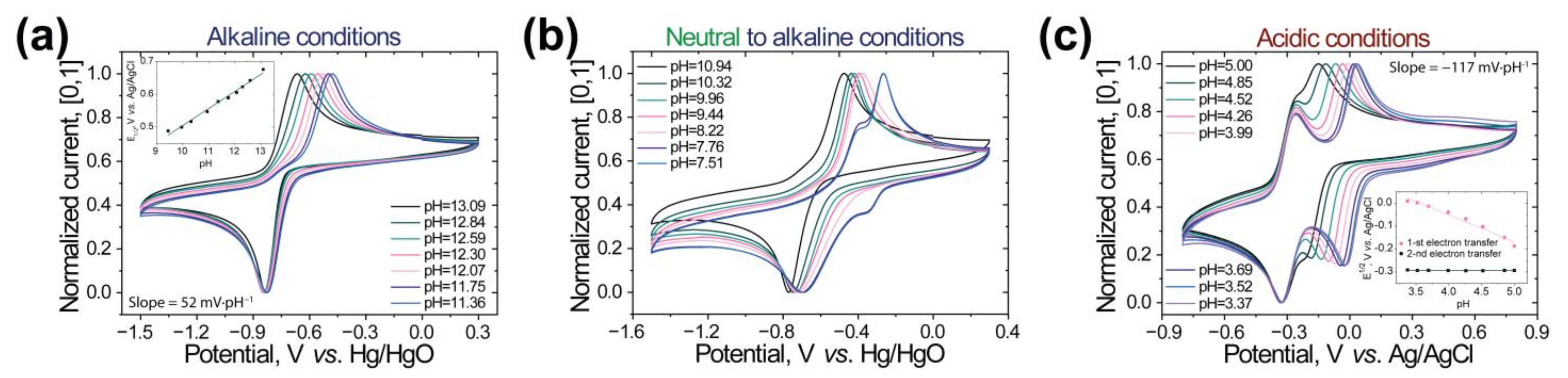
Figure 4.
(a) CVs of M1 and TEMPOL. (b) Discharge capacities vs. cycle number and Coulombic efficiencies of the h-cell based on 5 mM M1 and 10 mM TEMPOL with Nafion 117, Fumasep FAA-3PK-130, and Neosepta AHA membranes. (c) CV of the anolytes and catholytes before and after cycling of the h-cells with Fumasep-3PK-130 and Neosepta AHA membranes. (d) Electrochemical performance of the RFB with 3 mM M1 anolyte and 30 mM TEMPOL catholyte in 1.0 M NaCl water solution during 100 cycles. Cyclic Coulombic efficiency, charge, and discharge capacity as the functions of a number of cycles are presented. Battery charging and discharging time was limited to 8 000 s, that is, 138% of the theoretical battery capacity.
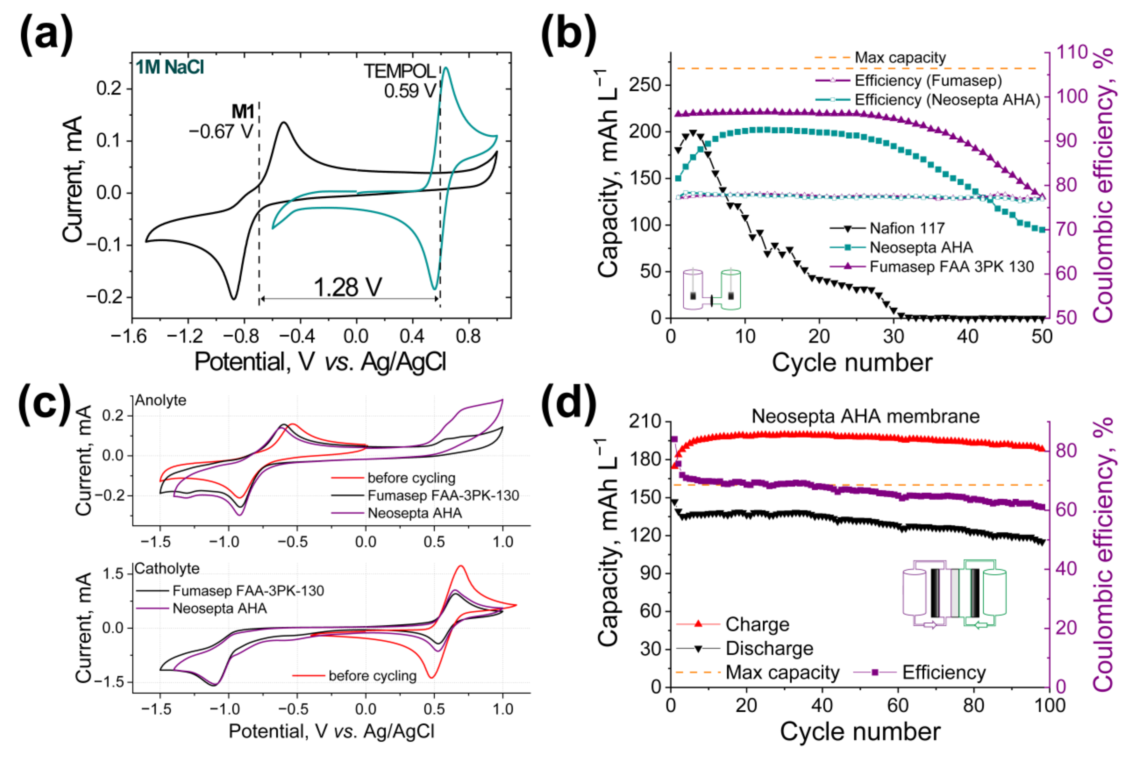
Figure 5.
Electrochemical performance of h-cell with 5 mM M1 anolyte and 15 mM K4Fe(CN)6 + 7.5 mM K3Fe(CN)6 catholyte in 1.0 M KOH water solution. Neosepta AHA membrane was used. Cyclic Coulombic efficiency, charge, and discharge capacity as the functions of a number of cycles are presented. (a) Cycling performed in galvanostatic mode. (b) Cycling performed in mixed galvanostatic + potentiostatic mode with the delay at the maximum and minimum potential of 2 h.
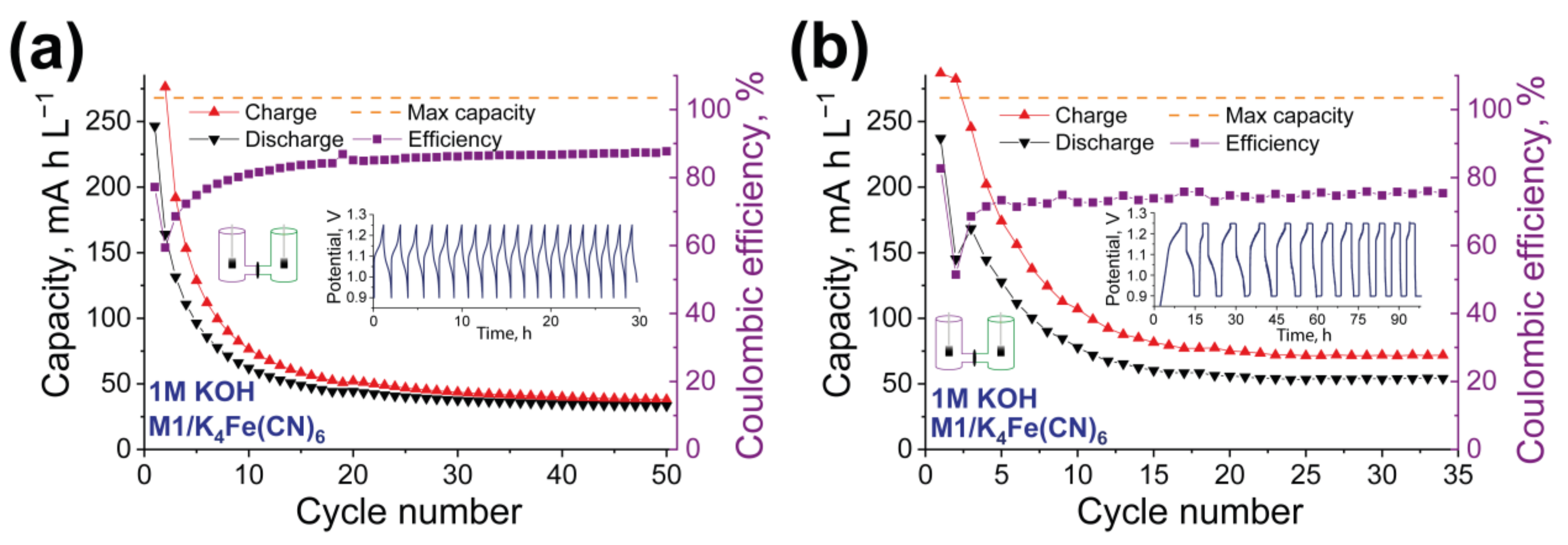
Figure 6.
Electrochemical performance of h-cell with 5 mM M1 anolyte and 15 mM VOSO4 catholyte in 1.0 M H2SO4 water solution. Cyclic Coulombic efficiency, charge, and discharge capacity as the functions of a number of cycles are presented in the case of application of galvanostatic (a) and mixed galvanostatic + potentiostatic mode with the delay at the maximum and minimum potential of 2 h (b). (c) Electrochemical performance of the RFB with 3 mM M1 anolyte and 10 mM VOSO4 catholyte in 1.0 M H2SO4 water solution during 160 cycles. Cyclic Coulombic efficiency, charge, and discharge capacity as the functions of a number of cycles are presented. (d) Electrochemical performance of the RFB with 20 mM M1 anolyte and 60 mM VOSO4 catholyte in 1.0 M H2SO4 water solution during 325 cycles. Cyclic Coulombic efficiency, charge, and discharge capacity as the functions of a number of cycles are presented.


Table 1.
The solubilities, redox potentials, stability under CV tests, diffusion coefficients, and kinetic parameters for M1 compound in different water-based SE.
Table 1.
The solubilities, redox potentials, stability under CV tests, diffusion coefficients, and kinetic parameters for M1 compound in different water-based SE.
| M1 | 1.0 M KOH | 1.0 M NaCl | 1.0 M H2SO4 |
| Solubility, M | 0.56 | 0.70 | 1.30 |
| E1/2 a, V | −0.85 | −0.67 | +0.05 (1st electron) −0.26 (2nd electron) |
| Cycling stability b | Stable | Stable | Stable |
| Kinetic rate constant(s) c, cm s−1 | 5.16 × 10⁻⁴ ± 8 × 10⁻⁷ | 2.59 × 10⁻⁴ ± 1 × 10⁻⁷ | - |
| M1 | 0.5 M KOH | 0.5 M NaCl | 0.5 M H2SO4 |
| Diffusion coefficient(s) d, cm2 s−1 c | 1.94 × 10⁻⁶ ± 3 × 10⁻⁹ | 9.64 × 10⁻⁷ ± 6 × 10⁻⁹ | 1st electron reduction 2.09 × 10⁻⁶ ± 5 × 10⁻¹⁰ 2nd electron reduction 5.66 × 10⁻⁶ ± 1 × 10⁻⁹ |
a Recorded at 100 mV s−1, using a glassy carbon WE, carbon CE, and Ag/AgCl RE in 1.0 M SE. b Stability tested within 100 CV cycles. c Calculated by Koutecký–Levich equation, followed by Tafel analysis. d Calculated by Levich equation for RDE.
Publisher’s Note: MDPI stays neutral with regard to jurisdictional claims in published maps and institutional affiliations. |
© 2022 by the authors. Licensee MDPI, Basel, Switzerland. This article is an open access article distributed under the terms and conditions of the Creative Commons Attribution (CC BY) license (https://creativecommons.org/licenses/by/4.0/).
Share and Cite
MDPI and ACS Style
Romadina, E.I.; Akkuratov, A.V.; Simoska, O.; Stevenson, K.J. Phenazine-Based Compound as a Universal Water-Soluble Anolyte Material for the Redox Flow Batteries. Batteries 2022, 8, 288. https://doi.org/10.3390/batteries8120288
AMA Style
Romadina EI, Akkuratov AV, Simoska O, Stevenson KJ. Phenazine-Based Compound as a Universal Water-Soluble Anolyte Material for the Redox Flow Batteries. Batteries. 2022; 8(12):288. https://doi.org/10.3390/batteries8120288
Chicago/Turabian StyleRomadina, Elena I., Alexander V. Akkuratov, Olja Simoska, and Keith J. Stevenson. 2022. "Phenazine-Based Compound as a Universal Water-Soluble Anolyte Material for the Redox Flow Batteries" Batteries 8, no. 12: 288. https://doi.org/10.3390/batteries8120288
Note that from the first issue of 2016, this journal uses article numbers instead of page numbers. See further details here.