Article

A New Charging Algorithm for Li-Ion Battery Packs Based on Artificial Neural Networks

by
João P. D. Faria
1,2,
Ricardo L. Velho
2,
Maria R. A. Calado
1,2,*,
José A. N. Pombo
2,
João B. L. Fermeiro
1,2 and
Sílvio J. P. S. Mariano
1,2
1
IT—Instituto de Telecomunicações, 6201-001 Covilhã, Portugal
2
Department of Electromechanical Engineering, Faculty of Engineering, University of Beira Interior, 6201-001 Covilhã, Portugal
*
Author to whom correspondence should be addressed.
Batteries 2022, 8(2), 18; https://doi.org/10.3390/batteries8020018
Submission received: 23 December 2021 / Revised: 1 February 2022 / Accepted: 11 February 2022 / Published: 15 February 2022
(This article belongs to the Special Issue Anode and Cathode Materials for Lithium-Ion and Sodium-Ion Batteries)

Abstract

:
This paper shows the potential of artificial intelligence (AI) in Li-ion battery charging methods by introducing a new charging algorithm based on artificial neural networks (ANNs). The proposed charging algorithm is able to find an optimized charging current profile, through ANNs, considering the real-time conditions of the Li-ion batteries. To test and validate the proposed approach, a low-cost battery management system (BMS) was developed, supporting up to 168 cells in series and n cells in parallel. When compared with the multistage charging algorithm, the proposed charging algorithm revealed a shorter charging time (7.85%) and a smaller temperature increase (32.95%). Thus, the results show that the proposed algorithm based on AI is able to effectively charge and balance batteries and can be regarded as a subject of interest for future research.

1. Introduction

Lithium-ion (Li-ion) batteries have emerged as an enabling technology, and several studies have included them in energy storage systems (ESSs) due to their characteristics, as follows: high specific energy, high energy density, high energy efficiency, high working cell voltage, long cycle life, no memory effects, relative low cost and low self-discharge rate [1,2].
Despite all the improvements and technological advances, Li-ion batteries still face some concerns and technical challenges. To address these challenges, some studies have been undertaken to develop new and more environmentally friendly Li-ion batteries with high performance/energy density as well as cost-efficiency and safety. Innovative materials and chemistries have been used to accelerate the design and optimization of the next generation of Li-ion batteries [3]. One of the most promising solutions is lithium–sulfur batteries (Li–S), which replace the cobalt cathodes of conventional Li-ion batteries with sulfur cathodes, producing thinner, lighter and lower-cost lithium batteries [4,5].
However, new lithium battery technologies raise several concerns. A key concern is the charging approach, essential to improve efficiency, charging time, battery aging and lifespan, and to avoid battery overcharging, one of the most severe safety problems for the large-scale application of Li-ion batteries [6]. To reduce charging time, higher charger rates are required to replenish the charge in the battery in the minimum possible time. However, this results in an accelerated battery capacity fade, leading to a lower lifespan and decreased charging efficiency due to the Joule heating effect [7,8].
Another concern is related to the inevitable need to interconnect multiple Li-ion batteries cells in series to obtain the required voltage levels. The intrinsic and extrinsic differences between cells result in a lack of uniformity that reduces usable capacity and, consequently, the performance of the pack. To address the above-mentioned concerns, some attempts have been made to improve Li-ion battery charging performance. However, designing proper charging approaches entails some technical challenges. For example, lowering battery charging time while increasing charging efficiency and extending lifespan are interrelated and antagonistic goals. Furthermore, constraints must be imposed (e.g., on current, voltage, and temperature) to protect the battery from overcharging and overheating, which can lead to premature degradation and safety issues [9].
To overcome these technical challenges, many charging approaches have been proposed. These can be roughly classified into the following four main groups: simple charging methods, optimized charging methods, model-based charging methods, and AC charging methods [10]. In simple charging methods, such as the constant-current (CC) or constant-voltage (CV) methods, one parameter (either current or voltage) remains constant throughout the entire charging process. However, these methods present several disadvantages and are rarely used in modern commercial applications [11]. To overcome these disadvantages, several optimized charging methods—such as CC/CV, multistage or pulse charging—were developed based on simple charging methods. To optimize these methods, some authors use AI based approaches to find the charging current profile, such as particle swarm optimization (PSO) [12,13], gray prediction [14,15], fuzzy control [16,17,18], ant colony algorithm [19], genetic algorithm (GA) [20] and Taguchi method [21,22].
Other authors use model-based charging methods to find the charging current profile [23,24,25]. These methods take advantage of battery models, such as equivalent circuit models (ECM) and electrochemical models (EM).
The AC charging methods, specifically the sinusoidal-ripple-current (SRC) method, has recently attracted much attention regarding Li-ion battery charging. In this type of methods, the AC impedance analysis is used to explore the optimal charging frequency.
In contrast to the aforementioned methods, the proposed approach uses artificial neural networks (ANNs) to determine the charging current profile and the balancing orders, based on the current state of the battery pack, i.e., the real time conditions of the pack. ANNs are a machine learning approach, inspired by the information processing of biologic neurons and their interconnections, to learn or discover underlying patterns embedded in the training dataset, without requiring any physical knowledge of the modeled system. There are many machines learning approaches that differ in terms of architecture, complexity, popularity, training methods and working principles, including the convolutional neural network (CNN), recurrent neural networks (RNNs), long short-term memory networks (LSTMs) and gated recurrent unit (GRU) [26]. However, when compared to other state-of-the-art machine learning approaches, ANNs are less complex (have fewer parameters to learn), easier to design, and have a lower computational cost, especially in the training process, i.e., they require a smaller training dataset to achieve similar results. For these reasons, ANNs are widely applied in the estimation and monitoring of several battery parameters, such as state-of-charge (SOC), state-of-health (SOH), state-of-function (SOF), and others (SOX) [27,28,29].
In this context, the proposed algorithm uses two multi-layer feed-forward neural networks (FFNN), one to estimate the cell balancing orders, and a second to estimate the battery pack charging current. One of the most important features of an ANN is how the learning/training process occurs, i.e., how internal states (weights and biases) are updated by extrapolating the input patterns for the desired output. Conventionally, this learning/training process uses gradient-based algorithms. Although these algorithms are very efficient in local exploration, they can converge prematurely into local minimums; they require continuity, convexity, and differentiability conditions; their efficiency is dependent upon initial positioning. To mitigate these limitations, both FFNNs were trained with the PSO algorithm.
The PSO is a metaheuristic population algorithm, well known for its simplicity of implementation and good performance, which has already shown excellent performance in the FFNN training process [30]. The use of ANNs applied to battery charging is novel and presents several advantages over the existing methods. For example, unlike simple charging methods that operate based on static battery parameters, the proposed approach can find the charging current profile considering the real-time conditions of the battery pack. When compared with optimized charging methods and model-based methods, the proposed approach has some key advantages. For instance, it does not require any physical knowledge of the modelled system, is able to generalize, and can detect complex nonlinear relationships between different battery pack parameters. Regarding the AC charging approach, the proposed method leads to a simpler control and easier implementation.
The use of ANNs applied to battery charging is a promising and innovative approach that allows shorter charging time and smaller temperature increase. Therefore, this approach is an interesting line for future research. Moreover, the proposed approach includes a cell balancing strategy based on ANNs, which is especially important to ensure the safety and efficiency of the system. To demonstrate the effectiveness of the proposed approach, a battery management system (BMS) platform with a passive balancing method was introduced. The implemented BMS is based on the Intersil ISL 94212 device, which enables a chain connection of up to a maximum of 14 devices, supporting systems up to 168SnP (168 cells in series and n cells in parallel). The Coulomb counting method was implemented to estimate state of charge (SOC). This method measures the charging/discharging current of a battery and integrates the current over time to estimate the SOC.
This paper is organized as follows: Section 2 presents a background on charging methods, balancing methods and artificial neural networks; Section 3 describes the proposed charging algorithm with cell balancing strategy based on two FFNNs and their training process with the PSO algorithm; Section 4 presents the implemented hardware, as well as the experimental results and compares the proposed approach with a multistage method, in terms of their charging time, cell temperature and cell voltage deviation; lastly, Section 5 concludes the paper and discusses the system implementation and algorithm.

2. Background

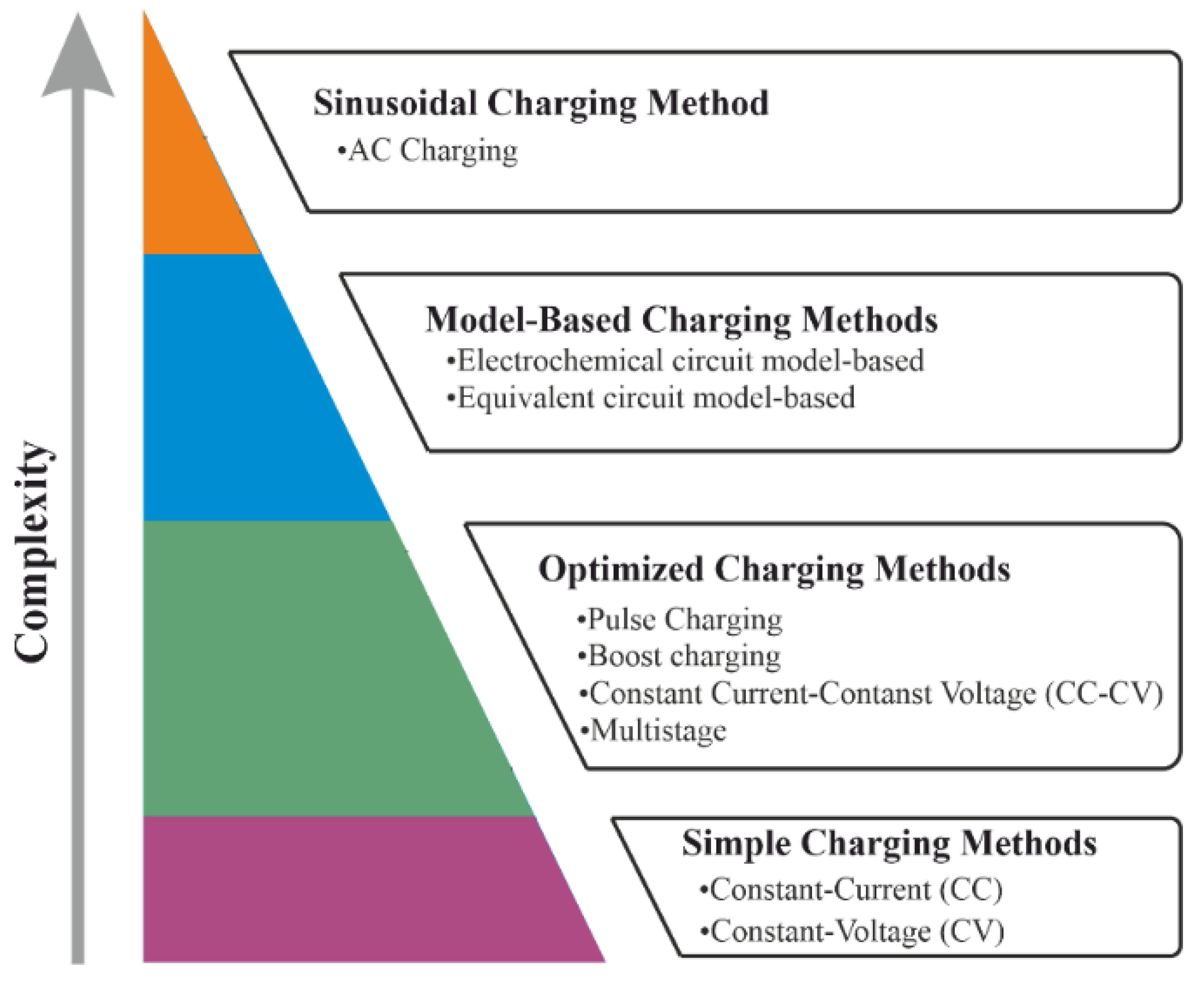
2.1. Charging Methods

Many charging methods have been reported in the literature, with various objectives, e.g., improving charging performance, charging time, energy loss, temperature rise, aging and lifespan. As seen in Figure 1, these methods can be roughly classified into the following four main groups with different levels of complexity: simple charging methods, optimized charging methods, model-based charging methods, and AC charging methods.
Simple charging methods are the most primitive charging approaches and can be divided into the CC and CV methods. In these charging approaches, one of the charging parameters, either current or voltage, remains constant throughout the charging process. However, due to the high currents used, battery lifespan may decrease [10].
Optimized charging methods were created to overcome the limitations of simple charging methods and can be divided into the following groups: multi-stage constant-current charging, constant-current/constant-voltage (CC/CV), boost charging, and pulse charging. The CC/CV method is the most popular strategy for Li-ion battery charging. It is divided into three distinct charging phases. In the first phase, named trickle charge (TC), the Li-ion battery is charged with a low charging current when cell voltage is below a critical value. When the Li-ion battery voltage is equal or higher than the critical value, the algorithm starts the second phase, named constant current (CC), wherein the Li-ion battery is subjected to a constant current until it reaches the full charge voltage. Then, the algorithm starts the third phase, named constant voltage (CV), when the Li-ion battery is subjected to a constant voltage until the minimum charging current or the charging time limit is reached [31,32].
The multistage method divides the charging time into different charging current stages [33]. In each current stage, the cell is charged with a lower current value than the previous stage. The criterion most often used to switch between stages (threshold crossing criterion) is when cells reach full charge voltage (typically 4.2 V). The authors in [34] proposed a new transition criterion based on the difference between the full charge voltage and the actual cell voltage, thereby reducing charging time and resulting in a small temperature increase. In [21], the authors proposed a new charging strategy whereby a Taguchi based PSO is used to search an optimal four-stage constant current pattern. Some authors use other optimization algorithms to find the best values of current for each stage, e.g., GA, Fuzzy, PSO and numerical optimization [11,20,35,36].
The pulse charge method can be divided into the following two different approaches: variable frequency pulse charge (VFPC) and variable duty pulse charge (VDPC). The basic idea of the VFPC is to optimize the frequency of the current pulse in order to minimize cell impedance (best electrochemical reaction of the battery) and, consequently, maximize energy transfer by varying the pulse amplitude while fixing pulse width, or vice versa [10,32,37]. There are many variants of this method. For example, in [38], the authors proposed a VFPC variant with the objective of determining the optimal charging frequency, i.e., the frequency for which the internal battery impedance is minimal and consequently energy transfer is maximum. Another variant was proposed in [39] with the same concept but using the VDPC. Boost charging consists of applying a very high current, during a short period, to charge a depleted battery and then switching to the standard CC–CV charging method. This method was first proposed in [40], and showed that it can charge a depleted battery to one-third of its rated capacity within 5 min. Another study [41] showed that the maximum boost charging current that could be safely applied to the tested high-energy cells was 6.7 times higher than the manufacturer-stated maximum.
The model-based charging methods calculate the charging current of a battery using the electrochemical model or the equivalent circuit model. The optimized charging process is achieved by controlling the polarization voltage. In addition, the equivalent circuit model can be combined with the temperature model, power loss model or the aging model to obtain a better charging performance [42]. In [43], a new model-based approach was proposed that resulted in significant improvement in terms of battery charging time and lifespan. In [1], the equivalent circuit model of Li-ion batteries was used to optimize the stages of the multistage method. The study shows that an optimal value for the multistage method can obtain faster charging, reduced capacity loss and longer cycle life.
Finally, the AC charging method seeks to charge Li-ion batteries at an optimal frequency (obtained from electrochemical impedance spectroscopy (EIS) analysis), thereby minimizing frequency-dependent impedance [44]. In [45], the authors proposed the sinusoidal-ripple-current, again based on the minimization of the internal impedance of the cell, allowing for maximum energy transfer.

2.2. Balancing Methodologies

There are two distinct methodologies for balancing Li-ion battery cells, as follows: active and passive methodologies. In passive methodologies, cells are balanced by discharging when the cell or pack is not being used, or by providing an alternative path for current flow during the charge operation. There are several distinct passive methodologies for Li-ion battery cells, such as the fixed shunt resistor, the shunt resistor, complete shunting, and the switched shunt resistor [46,47,48,49]. Passive methodologies are widely used due to their simplicity, cost, efficiency, volume, weight and robustness [46].
Active methodologies ideally use a non-dissipative process with external circuits, based on capacitors or inductors (DC–DC converters), to transfer energy among cells and balance the cell energy levels during the charge and discharge operation. Active balancing methodologies based on capacitors use a capacitor in parallel to transfer energy from a cell or pack with higher energy to a cell or pack with lower energy. Several balancing methodologies based on capacitors have been proposed, such as the modularized switched capacitor [46,47,49,50,51], double-tiered switched capacitor [46], automatic switched capacitor [52,53], single switched capacitor [49,50], chain structure of switched capacitor [51], and series-parallel switched capacitor [54,55]. Active balancing methodologies based on inductors use DC–DC converters (isolated or non-isolated) to transfer energy among cells. There are several active methodologies using isolated DC–DC converters, for example, the multi-winding transformer [46,47,48,49] and the multiple transformers [46,48]. An alternative is the use of non-isolated DC-DC converters, such as the buck, boost or buck-boost [48,56], the Cuk [48,49], full-bridge DC–DC [46,48] and the quasi-resonant converters [48,57].

3. Proposed Approach

3.1. Artificial Neural Networks

Although criticized as “black boxes” (making it harder to understand the possible correlations), FFNNs have proven to be a powerful tool and can approximate any continuous function, as established by the Universal Approximation Theorem [58]. Therefore, FFNNs can determine the charging current ( i k ) and the cell balancing orders (θk) in real-time. To perform an efficient and optimized control of the battery charging process, the proposed algorithm combines two FFNNs. The first FFNN (Figure 2a) is responsible for the determination of the charging current ( i k ). This FFNN uses the following three inputs to accurately determine the charging current: the difference between the full charge voltage ( f c V ) and the average cell voltage of the pack ( Ψ k ), which is represented by γ k ; the maximum difference between cell voltages ( ϕ k ); the pack temperature ( T k ), where k is the instant of time. The second FFNN (Figure 2b) estimates the balancing orders (θk) using the following three inputs: the average cell voltage of the pack ( Ψ k ), the voltage of each individual cell ( V i , k ), and the standard deviation of the pack voltage ( δ k ).
To ensure a reliable real-time charging current ( i k ), the FFNN1 training dataset was created with real data obtained through CC charging method wherein the Li-ion battery was subjected to different current values (from 0.25 A to 2 A with a 0.25 A step). Additionally, to improve the FFNN1 generalization capability, the training dataset was enriched with artificial data created according to security and operational guidelines. The obtained training dataset is represented in Figure 3, by a three-dimensional map that correlates: the maximum difference between cells voltages ( ϕ k ), the pack temperature ( T k and the difference between the full charge voltage and the average cell voltage of the pack ( γ k ).
As seen in Figure 3, the parameter γ k has a preponderant influence on the determination of the charging current, i.e., as the average cell voltage of the pack reaches the full charge voltage, the charging current must be reduced to protect the battery pack from overcharging and overheating. However, one must also consider the maximum difference between cells voltages. When the average cell voltage of the pack is far from the full charge voltage (4.2 V), the charging current only suffers a small decrease. As the average cell voltage of the pack gradually approaches the full charge voltage, the current is reduced to eliminate the imbalance between cells. Furthermore, the established guidelines prioritize the more effective top balancing. Another important aspect that can greatly affect battery pack lifespan is the operating temperature. Thus, to ensure a safe operation, the influence of temperature on the charging current is gradually increased, i.e., as the temperature rises the charging current is gradually reduced. However, if the pack operating temperature reaches 45 °C, the charging process is interrupted [59].
For the FFNN2 training process, the dataset was created according to Equations (1) and (2), such that when the voltage of each individual cell ( V i , k ) exceeds the average cell voltage of the pack ( γ k ) plus the standard deviation of the pack voltage ( δ k ) multiplied by coefficient α , the cell is considered balanced.
V i , k > γ k + δ k × α
α = 1 ( γ k f c V )
As can be seen in Figure 4, as the average cell voltage of the pack approaches the full charge voltage ( f c V ) , the voltage balancing threshold gradually becomes more stringent (by reducing coefficient α ), making the balancing process more demanding at the end of charging. This procedure allows a more effective balancing process at the end of the charging process (top balancing), when the charging current is lower and the balancing current is higher. Additionally, a safety rule was implemented, i.e., if any cell reaches the full charge voltage and the stopping criteria was not fulfilled, the cell is considered balanced.

3.2. Training Approach

The implemented training approach was an offline supervised method, using the particle swarm optimization (PSO) algorithm to optimize the FFNN’s internal states (weights and bias). The PSO algorithm is inspired by the working principles of cooperation and social behavior. This algorithm has a population of agents (particles), each one representing possible solutions and capable of communicating and cooperating with each other, creating solutions that “navigate” the multidimensional search space in search of an optimal solution. Each agent’s position is associated with a velocity, adjusted with an update equation that considers the individual and collective experiences, i.e., the agent’s own experience and the collective experience of the rest of the population. The basic idea is that agents move through space in search of an optimal solution. At each iteration, the algorithm evaluates every agent’s performance using a pre-defined objective function and then changes velocity towards the personal best performance until then ( x g b e s t ), as well as towards the best performance found among all particles ( x g b e s t ) [60].
Each agent’s velocity and position are determined using the following equations, respectively:
v i , d ( t + 1 ) = ϕ v i , d ( t ) + c 1 γ 1 ( x p b e s t , d ( t ) x i , d ( t ) ) + c 2 γ 2 ( x g b e s t , d ( t ) x i , d ( t ) )
x i , d ( t + 1 ) = x i , d ( t ) + v i , d ( t + 1 )
where, v i , d represents the velocity of the agent (i); x i , d is the position of the agent (i); ϕ is the inertia factor; c 1 and c 2 are the acceleration parameters; γ 1 and γ 2 are random numbers uniformly distributed between 0 and 1; x g b e s t is the agent’s personal best position; x g b e s t is the global best position; t represents the iteration; and d the problem dimension.
The flowchart of the implemented training approach is presented in Figure 5. This scheme generally illustrates the various steps, starting with dataset processing where the input dataset was normalized between −1 and 1, using the min–max normalizations method, thus ensuring a mean of 0 and a standard deviation of 1. Additionally, the input dataset was divided into two sets: the training set ( N t ) and the validation set ( N v ), corresponding to 75% and 25% of the data, respectively. Subsequently, all the variables and parameters were initiated, namely, the lower and upper bound (xlb and xub), the number of agents in the population, maximum number of iterations, and PSO control parameters.
Once the input dataset was created and all the variables and parameters were initiated, the problem dimension ( d a n n ) was calculated through Equation (5), which depends on the number of inputs ( m ), the number of neurons in the hidden layer ( n ), and the number of outputs ( o ).
d a n n = m × n + n × o + n + o
The agent initialization was carried out with the Nguyen–Widrow method [61]. Each agent i in the population is represented by Equation (6). The representation format includes the weights between neurons, and the bias of the hidden and output layer of each FFNN.
x i = ( w 1 , 1 , , w m , n W e i g h t s b e t w e e n t h e i n p u t t h e h i d d e n l a y e r , w 1 , 1 , , w n , o W e i g h t s b e t w e e n t h e h i d d e n t h e o u t p u t l a y e r , b 1 , , b n , b 1 , , b o B i a s o f t h e n e u r o n s t h e h i d d e n o u t p u t l a y e r s )
In each iteration, agents move through the multidimensional search space trying to minimize the learning error. Then, the performance of each agent is evaluated with the mean squared error (MSE) of the training dataset, expressed by Equation (7).
M S E = 1 N t i = 1 N t ( y ^ i y i ) 2
where y ^ i is the output response of the FFNN, y i is the target output and Nt is the number of samples of the training dataset.
Each particle’s velocity and position were updated with Equations (3) and (4), respectively. The hyperbolic strategy proposed in [62] was implemented, through successive iterations. In this strategy, if the lower or upper bound is exceeded, the movement of the particle is modified such that the new position is within the multidimensional search space. These procedures are represented by Equations (8) and (9).
v i , d ( t + 1 ) = v i , d ( t ) 1 + | v i , d ( t ) x u b , d x i , d ( t ) | i f   v i , d ( t + 1 ) > 0
v i , d ( t + 1 ) = v i , d ( t ) 1 + | v i , d ( t ) x i , d ( t ) x l b , d | i f   v i , d ( t + 1 ) < 0
There were two kinds of stopping criteria: the maximum number of iterations and a threshold based on the performance of the training and validation dataset. The latter is based on the MSE of the validation and training dataset given by x g b e s t in each iteration. This technique aims to find the exact moment when the FFNN starts to lose the ability to generalize (overfitting).

4. System Description and Experimental Results

4.1. System Description

The implemented system can be divided into the following three fundamental blocks: processing and control unit; acquisition and balancing unit; power unit. The implemented hardware blocks are shown in Figure 6. The processing and control unit can be subdivided into the following two distinct units: the main control unit and the auxiliary control unit. The main control unit algorithms were implemented in Mathworks Matlab® software running on a desktop workstation. This type of centralized control architecture allows great flexibility in the development of new charging algorithms with cell balancing strategies.
However, despite the flexibility, the workstation desktop that runs the main control unit algorithms does not natively support serial peripheral interface (SPI) communication (required by the acquisition and balancing unit). To solve this constraint, an auxiliary control unit was implemented to act as intermediary in the communication between the main control unit and the acquisition and balancing unit. This unit was based on a Texas Instruments® TMS320F28069 microcontroller.
The acquisition and balancing unit were based on an Intersil® ISL94212 device that allows a chain connection of up to 14 devices. Each device allows the simultaneous monitoring of 12 battery cells. In this study, the implemented system had 24 cells in series, resulting in a nominal power of 230 W/h.
Another important capability of this device is the possibility to easily implement low-cost balancing methods with few external components. Using this capability, the passive switched shunt resistor method, described in Figure 7, was implemented in this study. In this method, each cell in the pack is associated with a balancing resistor and a switch controlled by the ISL94212 device. The cells are balanced by discharging through a Rbal resistor (33Ohm) until all cells in the pack have reached the same voltage. However, the ISL94212 device only allows four temperature sensors. Therefore, using the capabilities of the TMS320F28069 microcontroller, a temperature acquisition system was developed to enable the use of a larger number of temperature sensors (in this case 12 sensors, 1 sensor for each 2 cells). Lastly, the power unit was the Magna-Power Electronics® DC SL 500-5.2 programmable power supply, which communicated through Standard Commands for Programmable Instruments (SCPI) with the main control unit.
As shown in Figure 8, the proposed charging process is categorized into four stages, as follows:
  • Stage 1. In this stage, all the system variables are initialized, and all the communication ports are configured. Additionally, the number of ISL94212 devices connected in the chain is checked and the initial voltages and temperatures of each battery pack is acquired.
  • Stage 2. The stop criteria, represented by Equations (10) and (11), is checked to verify if the battery packs are in charging condition or already fully charged.
V i , k 4.25
1 n i = 1 n V i , k f c V 1 n i = 1 n V i , k 0.01 V i , k 1 n i = 1 n V i , k + 0.01
where:
V i , k : Voltage of the i cell at time k ;
f c V : Full charge voltage (4.2 V);
n : Number of cells in the battery pack.
Equation (10) represents a safety criterion that prevents cell voltage from exceeding the threshold (4.25 V). The second equation establishes when charging results are considered acceptable, i.e., when the average cell voltage is greater than or equal to 4.2 V and all cells are within acceptable voltage limits (±0.01 V), at which point charging is interrupted and considered to have been successfully completed.
  • Stage 3. In this stage, the input data of the FFNNs is obtained. To accomplish this, the voltages and temperatures of each battery pack connected in the chain are acquired. When the acquisition process is complete, the data is passed through a moving average filter with the last six measured data points to reduce noise.
  • Stage 4. In this stage, the FFNN1 is executed, and the calculated charging current is communicated to the power unit through the SCPI.
  • Stage 5. Finally, FFNN2 is executed and then the output response value is evaluated in a comparison stage that normalizes the orders to binary values (0 or 1). Afterwards, the balancing orders are performed using the acquisition and balancing unit. The system then waits 60 s for the balancing process to finish in order to not compromise the accuracy of the next measurement process.

4.2. Experimental Results

The proposed algorithm was tested using 24 SAMSUNG ICR18650-26H 2600 mAh Li-ion battery cells [56], with reduced charge/discharge cycles. The results during the charging process with the proposed algorithm were also compared with the multistage method. Both charging algorithms were performed under the same conditions, i.e., the same stopping criteria and balancing algorithm, as previously explained. The multistage method was implemented with five current levels, using the conventional criterion of transition between current levels, i.e., transition occurs when a cell reaches the full charge voltage (4.2 V). The number of current levels was chosen based on the study carried out by [60], which concluded that the difference between applying different numbers of charging current levels is almost negligible when the number of charging current levels is greater than five.
Figure 9 presents the charging current profiles, the battery pack temperature, the difference between the full charge voltage and the average cell voltage of the pack and, finally, the maximum difference between cell voltages, for both experimental tests. For the proposed algorithm, the current had an initial value of 1.64 A (Figure 9a), due to a considerable difference between the cell voltages of 0.07 V (Figure 9b). After 4 min and 40 s, the current reached the maximum value of 2.18 A, due to a decrease in the difference between cell voltages (0.03 V at that moment). During the remaining charge, there was an oscillatory profile in the current. This is justified by the difference between cell voltages, i.e., when there is an increase in the cell voltage difference, there is a decrease in the charge current, and vice versa. Although there was a slight difference between cell voltages during the entire charging process, this difference was gradually reduced as the charging progressed, ending the charging process with a value of 0.01 V. As seen in Figure 9c, the difference between the full charge voltage and the average cell voltage followed the expected profile, i.e., a gradual decrease until the end of the charge, with steeper slopes when the charging current was higher. Additionally, the temperature did not exceed the predefined values for the cells, reaching a maximum value of only 33.59 °C, corresponding to a 9.28 °C temperature variation.
Figure 9b shows the current profile for the multistage method. The first transition between current levels occurred after 55 min and 40 s. However, the cell voltage exceeded the full charge voltage (4.2 V) and remained above this value for 3 min and 30 s. Therefore, and given the sampling time (60 s), the algorithm only performed one iteration at the second and third current levels. After 3 min and 30 s, the cell voltage dropped below 4.2 V and the charging current was fixed at the fourth level. This behavior occurred again in the next transition, but due to the absence of more current levels, the current was fixed at the fifth level. Figure 9d demonstrates that a much higher temperature value was obtained when compared with the proposed algorithm, due to the high charging time at high currents, reaching a maximum value of 38.68 °C, corresponding to a gradient of 13.84 °C.
Figure 10 shows the individual voltage of each cell in the pack for both experimental tests. As aforementioned, in the tests performed with the proposed algorithm (Figure 10a), the difference between cell voltages decreased towards the end of charging. The magnification of this final stage (in Figure 10a) clearly reveals how the charging process was completed successfully, fulfilling the stopping criteria with an average cell voltage of 4.203 V and a difference between cell voltages of 0.01 V. In contrast, in the experimental test with the multistage method (Figure 10b), there was a reduced difference between cell voltages throughout the charging process and there was a higher slope in voltage until the first transition, which is justified by the high charging current of 2.5 A. The zoom in Figure 10b shows the fulfillment of the stopping criteria (an average cell voltage of 4.202 V and a difference between cell voltages of 0.01 V), confirming once again the excellent results obtained by the proposed balancing algorithm.
Figure 11 illustrates the number of cells that required balancing during the charging process for both experimental tests, demonstrating the excellent performance of the proposed balancing algorithm using the FFNNs. For the proposed algorithm, after 1 h and 30 min of charging there was an increase in the number of cells that required balancing (Figure 11a), since the proposed algorithm privileges top balancing, making the balancing process more stringent at the end of the charging process. Before 1 h and 30 min of charging, few cells needed to be balanced, because balancing in this period is not very effective (compared with balancing performed at end of charging) and is only carried out to mitigate and prevent a higher difference between cell voltages. At the end of the charging process and since the stopping criteria were not met, all cells exceeded 4.2 V and, consequently, all cells were balanced. This procedure is essential to prevent cell voltage from further exceeding the full charge voltage (4.2 V) and allowing the stopping criteria to be met (Equations (10) and (11)).
Figure 11b presents the results for the experimental test with the multistage method. At the transition between current levels, all the cells required balancing, because all cells exceeded the full charge voltage. At the end of charging, as in the previous experimental test, all cells required balancing. For both experimental tests, the proposed balancing algorithm presented excellent results, managing to minimize the difference between cell voltages and reaching the predetermined stopping criteria. Therefore, it is important to note that regardless of the charging algorithm, the proposed balancing algorithm managed to overcome the existent difference between cell voltages.
Table 1 summarizes the performance of both charging algorithms concerning the charging time, difference between cell voltages at the end of the charging process, and temperature increase.
When compared to the multistage method, the proposed algorithm presented superior results, achieving a 7.85% reduction in charging time and a 32.95% reduction in temperature increase. Regarding the difference between cell voltages at the end of the charging process, the proposed balancing algorithm was able to reduce this difference throughout the charging process, in both cases ending with the same difference. Therefore, it should be noted that the proposed charging algorithm achieved a major reduction in charging time and in temperature increase.

5. Conclusions

This paper presents a new charging algorithm and a new battery-balancing strategy for Li-ion batteries that reduces charging time and temperature increase. The proposed charging algorithm determines, through an FFNN, the charging current profile, considering the real-time conditions of the batteries, i.e., considering the difference between the full charge voltage and the average pack voltage, the difference between cell voltages and the battery temperature. When compared with the multistage algorithm, it showed better results regarding charging time and temperature increase. Additionally, the proposed charging method was able to adapt to different battery conditions, as it adapts to the actual state of the battery pack. Another distinctive feature of the proposed charging method is the cell balancing capability, which is especially important to maintain a safe and efficient operation. The balancing orders were calculated considering the average pack voltage, the voltage of each individual cell, and the standard deviation of the battery pack. The proposed balancing strategy was able to eliminate the difference between the voltage of the cells throughout the charging process, presenting an excellent performance. To compare the robustness and versatility of the proposed balancing strategy, the multistage algorithm was also implemented. Both cases resulted in the same difference between cell voltages. However, when compared to the multistage method, the proposed algorithm presented superior results, achieving a 7.85% reduction in charging time and a 32.95% reduction in temperature increase.

Author Contributions

Conceptualization, J.P.D.F., R.L.V., J.A.N.P. and J.B.L.F.; methodology, J.P.D.F., R.L.V. and J.A.N.P.; software, J.P.D.F., R.L.V. and J.A.N.P.; validation, J.A.N.P., M.R.A.C. and S.J.P.S.M.; investigation, J.P.D.F., R.L.V., J.A.N.P., M.R.A.C., J.B.L.F., S.J.P.S.M.; formal analysis, M.R.A.C. and S.J.P.S.M.; writing—original draft preparation, J.P.D.F., R.L.V. and J.A.N.P.; writing—review and editing, S.J.P.S.M. and M.R.A.C.; visualization, J.P.D.F. and J.A.N.P.; supervision, J.A.N.P., S.J.P.S.M. and M.R.A.C. All authors have read and agreed to the published version of the manuscript.

Funding

This work is funded by FCT/MCTES through national funds and when applicable co-funded EU funds under the project UIDB/50008/2020.

Institutional Review Board Statement

Not applicable.

Informed Consent Statement

Not applicable.

Data Availability Statement

Not applicable.

Acknowledgments

J.P.D.Faria was supported by the doctoral Grant SFRH/BD/151349/2021 financed by the Portuguese Foundation for Science and Technology (FCT), and with funds from MPP2030, under MIT Portugal Program.

Conflicts of Interest

The authors declare no conflict of interest.

References

  1. Khan, A.B.; Choi, W. Optimal Charge Pattern for the High-Performance Multistage Constant Current Charge Method for the Li-Ion Batteries. IEEE Trans. Energy Convers. 2018, 33, 1132–1140. [Google Scholar] [CrossRef]
  2. Wu, T.; Liu, X.; Zhang, X.; Lu, Y.; Wang, B.; Deng, Q.; Yang, Y.; Wang, E.; Lyu, Z.; Li, Y.; et al. Full Concentration Gradient-Tailored Li-Rich Layered Oxides for High-Energy Lithium-Ion Batteries. Adv. Mater. 2021, 33, 2001358. [Google Scholar] [CrossRef] [PubMed]
  3. El Kharbachi, A.; Zavorotynska, O.; Latroche, M.; Cuevas, F.; Yartys, V.; Fichtner, M. Exploits, Advances and Challenges Benefiting beyond Li-Ion Battery Technologies. J. Alloys Compd. 2020, 817, 153261. [Google Scholar] [CrossRef]
  4. Li, S.; Leng, D.; Li, W.; Qie, L.; Dong, Z.; Cheng, Z.; Fan, Z. Recent Progress in Developing Li2S Cathodes for Li–S Batteries. Energy Storage Mater. 2020, 27, 279–296. [Google Scholar] [CrossRef]
  5. Su, Y.S.; Fu, Y.; Cochell, T.; Manthiram, A. A Strategic Approach to Recharging Lithium-Sulphur Batteries for Long Cycle Life. Nat. Commun. 2013, 4, 2985. [Google Scholar] [CrossRef]
  6. Ren, D.; Feng, X.; Lu, L.; He, X.; Ouyang, M. Overcharge Behaviors and Failure Mechanism of Lithium-Ion Batteries under Different Test Conditions. Appl. Energy 2019, 250, 323–332. [Google Scholar] [CrossRef]
  7. Mandli, A.R.; Ramachandran, S.; Khandelwal, A.; Kim, K.Y.; Hariharan, K.S. Fast Computational Framework for Optimal Life Management of Lithium Ion Batteries. Int. J. Energy Res. 2018, 42, 1973–1982. [Google Scholar] [CrossRef]
  8. Rodrigues, M.T.F.; Son, S.-B.; Colclasure, A.M.; Shkrob, I.A.; Trask, S.E.; Bloom, I.D.; Abraham, D.P. How Fast Can a Li-Ion Battery Be Charged? Determination of Limiting Fast Charging Conditions. ACS Appl. Energy Mater. 2021, 4, 1063–1068. [Google Scholar] [CrossRef]
  9. Liu, K.; Zou, C.; Li, K.; Wik, T. Charging Pattern Optimization for Lithium-Ion Batteries With an Electrothermal-Aging Model. IEEE Trans. Ind. Inform. 2018, 14, 5463–5474. [Google Scholar] [CrossRef]
  10. Lin, Q.; Wang, J.; Xiong, R.; Shen, W.; He, H. Towards a Smarter Battery Management System: A Critical Review on Optimal Charging Methods of Lithium Ion Batteries. Energy 2019, 183, 220–234. [Google Scholar] [CrossRef]
  11. Wang, S.C.; Liu, Y.H. A PSO-Based Fuzzy-Controlled Searching for the Optimal Charge Pattern of Li-Ion Batteries. IEEE Trans. Ind. Electron. 2015, 62, 2983–2993. [Google Scholar] [CrossRef]
  12. Faisal, M.; Hannan, M.A.; Ker, P.J.; Rahman, M.S.A.; Begum, R.A.; Mahlia, T.M.I. Particle Swarm Optimised Fuzzy Controller for Charging–Discharging and Scheduling of Battery Energy Storage System in MG Applications. Energy Rep. 2020, 6, 215–228. [Google Scholar] [CrossRef]
  13. Kalogiannis, T.; Hosen, M.S.; Gandoman, F.H.; Sokkeh, M.A.; Jaguemont, J.; Berecibar, M.; van Mierlo, J. Multi-Objective Particle Swarm Optimization and Training of Datasheet-Based Load Dependent Lithium-Ion Voltage Models. Int. J. Electr. Power Energy Syst. 2021, 133, 107312. [Google Scholar] [CrossRef]
  14. Chen, L.R.; Hsu, R.C.; Liu, C.S. A Design of a Grey-Predicted Li-Ion Battery Charge System. IEEE Trans. Ind. Electron. 2008, 55, 3692–3701. [Google Scholar] [CrossRef]
  15. Chen, L.-R.; Hsu, R.C.; Liu, C.S.; Yang, H.-Y.; Chu, N.-Y. A Grey-Predicted Li-Ion Battery Charge System. In Proceedings of the 30th Annual Conferenceof the IEEE industrlal Electronics Society, Busan, South Korea, 2–6 November 2004; pp. 502–507. [Google Scholar]
  16. Li, C.Y.; Liu, G.P. Optimal Fuzzy Power Control and Management of Fuel Cell/Battery Hybrid Vehicles. J. Power Sources 2009, 192, 525–533. [Google Scholar] [CrossRef]
  17. Mansiri, K.; Sukchai, S.; Sirisamphanwong, C. Fuzzy Control Algorithm for Battery Storage and Demand Side Power Management for Economic Operation of the Smart Grid System at Naresuan University, Thailand. IEEE Access 2018, 6, 32440–32449. [Google Scholar] [CrossRef]
  18. Faisal, M.; Hannan, M.A.; Ker, P.J.; Lipu, M.S.H.; Uddin, M.N. Fuzzy-Based Charging—Discharging Controller for Lithium-Ion Battery in Microgrid Applications. IEEE Trans. Ind. Appl. 2021, 57, 4187–4195. [Google Scholar] [CrossRef]
  19. Liu, Y.-H.; Teng, J.-H.; Lin, Y.-C. Search for an Optimal Rapid Charging Pattern for Lithium–Ion Batteries Using Ant Colony System Algorithm. IEEE Trans. Ind. Electron. 2005, 52, 1328–1336. [Google Scholar] [CrossRef]
  20. Guo, Z.; Liaw, B.Y.; Qiu, X.; Gao, L.; Zhang, C. Optimal Charging Method for Lithium Ion Batteries Using a Universal Voltage Protocol Accommodating Aging. J. Power Sources 2015, 274, 957–964. [Google Scholar] [CrossRef]
  21. Lee, C.; Chang, T.; Hsu, S.; Jiang, J. Taguchi-Based PSO for Searching an Optimal Four-Stage Charge Pattern of Li-Ion Batteries. J. Energy Storage 2019, 21, 301–309. [Google Scholar] [CrossRef]
  22. Amanor-boadu, J.M.; Guiseppi-Elie, A.; Sánchez-Sinencio, E. Search for Optimal Pulse Charging Parameters for Li-Ion Polymer Batteries Using Taguchi Orthogonal Arrays. IEEE Trans. Ind. Electron. 2018, 65, 8982–8992. [Google Scholar] [CrossRef]
  23. Perez, H.E.; Hu, X.; Dey, S.; Moura, S.J. Optimal Charging of Li-Ion Batteries with Coupled Electro-Thermal-Aging Dynamics. IEEE Trans. Veh. Technol. 2017, 66, 7761–7770. [Google Scholar] [CrossRef]
  24. Zou, C.; Hu, X.; Wei, Z.; Wik, T.; Egardt, B. Electrochemical Estimation and Control for Lithium-Ion Battery Health-Aware Fast Charging. IEEE Trans. Ind. Electron. 2018, 65, 6635–6645. [Google Scholar] [CrossRef]
  25. Wang, S.; Kuang, K.; Han, X.; Chu, Z.; Lu, L.; Ouyang, M. A Model-Based Continuous Differentiable Current Charging Approach for Electric Vehicles in Direct Current Microgrids. J. Power Sources 2021, 482, 229019. [Google Scholar] [CrossRef]
  26. Chen, J.C.; Chen, T.L.; Liu, W.J.; Cheng, C.C.; Li, M.G. Combining Empirical Mode Decomposition and Deep Recurrent Neural Networks for Predictive Maintenance of Lithium-Ion Battery. Adv. Eng. Inform. 2021, 50, 101405. [Google Scholar] [CrossRef]
  27. Yang, Q.; Xu, J.; Li, X.; Xu, D.; Cao, B. State-of-Health Estimation of Lithium-Ion Battery Based on Fractional Impedance Model and Interval Capacity. Int. J. Electr. Power Energy Syst. 2020, 119, 105883. [Google Scholar] [CrossRef]
  28. Rastegarpanah, A.; Hathaway, J.; Ahmeid, M.; Lambert, S.; Walton, A.; Stolkin, R. A Rapid Neural Network–Based State of Health Estimation Scheme for Screening of End of Life Electric Vehicle Batteries. Proc. Inst. Mech. Eng. Part I J. Syst. Control Eng. 2020, 235, 330–346. [Google Scholar] [CrossRef]
  29. Chandran, V.; Patil, C.K.; Karthick, A.; Ganeshaperumal, D.; Rahim, R.; Ghosh, A. State of Charge Estimation of Lithium-Ion Battery for Electric Vehicles Using Machine Learning Algorithms. World Electr. Veh. J. 2021, 12, 38. [Google Scholar] [CrossRef]
  30. Ashraf, A.; Bangyal, W.H.; Rauf, H.T.; Pervaiz, S.; Ahmad, J. Training of Artificial Neural Network Using New Initialization Approach of Particle Swarm Optimization for Data Classification. In Proceedings of the 2020 International Conference on Emerging Trends in Smart Technologies (ICETST), Karachi, Pakistan, 26–27 March 2020. [Google Scholar] [CrossRef]
  31. Hussein, A.A.H.; Batarseh, I. A Review of Charging Algorithms for Nickel and Lithium Battery Chargers. IEEE Trans. Veh. Technol. 2011, 60, 830–838. [Google Scholar] [CrossRef]
  32. Shen, W.; Vo, T.T.; Kapoor, A. Charging Algorithms of Lithium-Ion Batteries: An Overview. In Proceedings of the 2012 7th IEEE Conference on Industrial Electronics and Applications (ICIEA), Singapore, 18–20 July 2012; pp. 1567–1572. [Google Scholar] [CrossRef]
  33. Keil, P.; Jossen, A. Charging Protocols for Lithium-Ion Batteries and Their Impact on Cycle Life—An Experimental Study with Different 18650 High-Power Cells. J. Energy Storage 2016, 6, 125–141. [Google Scholar] [CrossRef]
  34. Velho, R.; Beirão, M.; Calado, M.D.R.; Pombo, J.; Fermeiro, J.; Mariano, S. Management System for Large Li-Ion Battery Packs with a New Adaptive Multistage Charging Method. Energies 2017, 10, 605. [Google Scholar] [CrossRef]
  35. Liu, C.L.; Wang, S.C.; Chiang, S.S.; Liu, Y.H.; Ho, C.H. PSO-Based Fuzzy Logic Optimization of Dual Performance Characteristic Indices for Fast Charging of Lithium-Ion Batteries. In Proceedings of the 2013 IEEE 10th International Conference on Power Electronics and Drive Systems (PEDS), Kitakyushu, Japan, 22–25 April 2013; pp. 474–479. [Google Scholar] [CrossRef]
  36. Mathieu, R.; Briat, O.; Gyan, P.; Vinassa, J.M. Fast Charging for Electric Vehicles Applications: Numerical Optimization of a Multi-Stage Charging Protocol for Lithium-Ion Battery and Impact on Cycle Life. J. Energy Storage 2021, 40, 102756. [Google Scholar] [CrossRef]
  37. Yin, M.; Cho, J.; Park, D. Pulse-Based Fast Battery IoT Charger Using Dynamic Frequency and Duty Control Techniques Based on Multi-Sensing of Polarization Curve. Energies 2016, 9, 209. [Google Scholar] [CrossRef]
  38. Chen, L.-R. A Design of an Optimal Battery Pulse Charge System by Frequency-Varied Technique. IEEE Trans. Ind. Electron. 2007, 54, 398–405. [Google Scholar] [CrossRef]
  39. Chen, L.R. Design of Duty-Varied Voltage Pulse Charger for Improving Li-Ion Battery-Charging Response. IEEE Trans. Ind. Electron. 2009, 56, 480–487. [Google Scholar] [CrossRef]
  40. Notten, P.H.L.; Op, J.H.G.; Beek, J.R.G. Van Boostcharging Li-Ion Batteries: A Challenging New Charging Concept. J. Power Sources 2005, 145, 89–94. [Google Scholar] [CrossRef]
  41. Amietszajew, T.; Mcturk, E.; Fleming, J.; Bhagat, R. Understanding the Limits of Rapid Charging Using Instrumented Commercial 18650 High-Energy Li-Ion Cells. Electrochim. Acta 2018, 263, 346–352. [Google Scholar] [CrossRef]
  42. Liu, J.; Duan, Q.; Chen, H.; Sun, J.; Wang, Q. An Optimal Multistage Charge Strategy for Commercial Lithium Ion Battery. Sustain. Energy Fuels 2018, 2, 1726–1736. [Google Scholar] [CrossRef]
  43. Santucci, A.; Sorniotti, A.; Lekakou, C. Power Split Strategies for Hybrid Energy Storage Systems for Vehicular Applications. J. Power Sources 2014, 258, 395–407. [Google Scholar] [CrossRef] [Green Version]
  44. Cho, S.Y.; Lee, I.O.; Baek, J.I.; Moon, G.W. Battery Impedance Analysis Considering DC Component in Sinusoidal Ripple-Current Charging. IEEE Trans. Ind. Electron. 2016, 63, 1561–1573. [Google Scholar] [CrossRef]
  45. Chen, L.R.; Wu, S.L.; Shieh, D.T.; Chen, T.R. Sinusoidal-Ripple-Current Charging Strategy and Optimal Charging Frequency Study for Li-Ion Batteries. IEEE Trans. Ind. Electron. 2013, 60, 88–97. [Google Scholar] [CrossRef]
  46. Gallardo-Lozano, J.; Romero-Cadaval, E.; Milanes-Montero, M.I.; Guerrero-Martinez, M.A. Battery Equalization Active Methods. J. Power Sources 2014, 246, 934–949. [Google Scholar] [CrossRef]
  47. Cao, J.; Schofield, N.; Emadi, A. Battery Balancing Methods: A Comprehensive Review. In Proceedings of the 2008 IEEE Vehicle Power and Propulsion Conference, Harbin, China, 3–5 September 2008; pp. 3–8. [Google Scholar] [CrossRef]
  48. Daowd, M.; Omar, N.; van den Bossche, P.; van Mierlo, J. A Review of Passive and Active Battery Balancing Based on MATLAB/Simulink. Int. Rev. Electr. Eng. 2011, 6, 2974–2989. [Google Scholar] [CrossRef]
  49. Qi, J.; Dah-Chuan Lu, D. Review of Battery Cell Balancing Techniques. In Proceedings of the 2014 Australasian Universities Power Engineering Conference (AUPEC), Perth, Australia, 28 September–1 October 2014; pp. 1–6. [Google Scholar] [CrossRef]
  50. Raman, S.R.; Xue, X.D.; Cheng, K.W.E. Review of Charge Equalization Schemes for Li-Ion Battery and Super-Capacitor Energy Storage Systems. In Proceedings of the 2014 International Conference on Advances in Electronics, Computers and Communications, Bangalore, India, 10–11 October 2014. [Google Scholar]
  51. Kim, M.-Y.; Kim, C.-H.; Kim, J.-H.; Moon, G.-W. A Chain Structure of Switched Capacitor for Improved Cell Balancing Speed of Lithium-Ion Batteries. IEEE Trans. Ind. Electron. 2014, 61, 3989–3999. [Google Scholar] [CrossRef]
  52. Ye, Y.; Cheng, K. An Automatic Switched-Capacitor Cell Balancing Circuit for Series-Connected Battery Strings. Energies 2016, 9, 138. [Google Scholar] [CrossRef] [Green Version]
  53. Ho, K.C.; Liu, Y.H.; Ye, S.P.; Chen, G.J.; Cheng, Y.S. Mathematical Modeling and Performance Evaluation of Switched-Capacitor-Based Battery Equalization Systems. Electronics 2021, 10, 2629. [Google Scholar] [CrossRef]
  54. Ye, Y.; Cheng, K.W.E. Modeling and Analysis of Series-Parallel Switched-Capacitor Voltage Equalizer for Battery/Supercapacitor Strings. IEEE J. Emerg. Sel. Top. Power Electron. 2015, 3, 977–983. [Google Scholar] [CrossRef]
  55. Xu, B.; Liu, L.; Wang, S.; Lin, Z.; Mai, R. A Series-Parallel Resonance-Switched-Capacitor Equalizer for the Hybrid Energy Storage System Based on Cascade Utilization. In Proceedings of the 2021 IEEE 2nd China International Youth Conference on Electrical Engineering (CIYCEE), Chengdu, China, 15–17 December 2021; pp. 1–6. [Google Scholar] [CrossRef]
  56. Zhang, Y.; Yang, R. An Improved Buck-Boost Circuit Equalization Method for Series Connected Battery Packs. In Proceedings of the 2021 IEEE 4th International Electrical and Energy Conference (CIEEC), Wuhan, China, 28–30 May 2021. [Google Scholar] [CrossRef]
  57. Wu, Q.; Gao, M.; Lin, H.; Dong, Z. A Bimodal Multichannel Battery Pack Equalizer Based on a Quasi-Resonant Two-Transistor Forward Converter. Energies 2021, 14, 1112. [Google Scholar] [CrossRef]
  58. Tang, S.; Yang, Y. Why Neural Networks Apply to Scientific Computing? Theor. Appl. Mech. Lett. 2021, 11, 100242. [Google Scholar] [CrossRef]
  59. SAMSUNG. Specification of Product for Lithium-Ion Rechargeable Cell-Model: ICR18650-26H; Samsung SDI Co., Ltd.: Yongin-si, Korea, 2011. [Google Scholar]
  60. Nunes, H.G.G.; Pombo, J.A.N.; Bento, P.M.R.; Mariano, S.J.P.S.; Calado, M.R.A. Collaborative Swarm Intelligence to Estimate PV Parameters. Energy Convers. Manag. 2019, 185, 866–890. [Google Scholar] [CrossRef]
  61. Nguyen, D.; Widrow, B. Improving the Learning Speed of 2-Layer Neural Networks by Choosing Initial Values of the Adaptive Weights. In Proceedings of the 1990 IJCNN International Joint Conference on Neural Networks, San Diego, CA, USA, 17–21 June 1990. [Google Scholar]
  62. Ruan, D.; Montero, J.; Lu, J.; Martinez, L.; D’hondt, P.; Kerre, E.E. Computational Intelligence in Decision and Control. In Proceedings of the 8th International FLINS Conference, Madrid, Spain, 21–24 September 2008; Volume 21, p. 24. [Google Scholar] [CrossRef] [Green Version]
Figure 1. Charging methods main groups.
Batteries 08 00018 g001
Figure 2. Representation of the proposed architectures: (a) implemented FFNN to estimate the charging current; (b) implemented FFNN to estimate the balancing orders.
Batteries 08 00018 g002
Figure 3. Representation of FFNN1 training dataset.
Batteries 08 00018 g003
Figure 4. Representation of FFNN2 training dataset.
Batteries 08 00018 g004
Figure 5. Flowchart of training algorithm.
Batteries 08 00018 g005
Figure 6. Implemented system diagram.
Batteries 08 00018 g006
Figure 7. Implemented passive switched shunt resistor method.
Batteries 08 00018 g007
Figure 8. Implemented system flowchart.
Batteries 08 00018 g008
Figure 9. (a,b) current profiles for the proposed algorithm and the multistage method, respectively; (c,d) charging parameters for the proposed algorithm and the multistage method, respectively.
Batteries 08 00018 g009
Figure 10. Voltage of each cell for: (a) proposed algorithm; (b) multistage algorithm.
Batteries 08 00018 g010
Figure 11. Number of cells balanced during charge for: (a) proposed algorithm; (b) multistage algorithm.
Batteries 08 00018 g011
Table 1. Comparison between the proposed charging algorithm and the multistage method.
Charging Time (h)Difference Between Cell Voltages (V)Temperature Increase (°C)
Multistage with five current levels2.420.0113.84
Proposed charging
Algorithm
2.230.019.28
Publisher’s Note: MDPI stays neutral with regard to jurisdictional claims in published maps and institutional affiliations.

