
Progress and Prospect of Practical Lithium-Sulfur Batteries Based on Solid-Phase Conversion
by
Yikun Yi
1,
Feng Hai
1,
Jingyu Guo
1,
Xiaolu Tian
1,
Shentuo Zheng
1,
Zhendi Wu
1,
Tao Wang
2,* and
Mingtao Li
1,* 1
Shaanxi Key Laboratory of Energy Chemical Process Intensification, School of Chemical Engineering and Technology, Xi’an Jiaotong University, No. 28, Xianning West Road, Xi’an 710049, China
2
School of Materials Science and Engineering, Dongguan University of Technology, Dongguan 523808, China
*
Authors to whom correspondence should be addressed.
Batteries 2023, 9(1), 27; https://doi.org/10.3390/batteries9010027
Submission received: 1 November 2022
/
Revised: 5 December 2022
/
Accepted: 21 December 2022
/
Published: 29 December 2022
(This article belongs to the Special Issue Lithium-Sulfur Batteries: Research Progress of Key Materials)
Abstract
:Lithium–sulfur (Li–S) batteries hold great promise in the field of power and energy storage due to their high theoretical capacity and energy density. However, the “shuttle effect” that originates from the dissolution of intermediate lithium polysulfides (LiPSs) during the charging and discharging process is prone to causing continuous irreversible capacity loss, which restricts the practical development. Beyond the traditional Li–S batteries based on the dissolution-diffusion mechanism, novel Li–S batteries based on solid-phase conversion exhibit superior cycling stability owing to the absolute prevention of polysulfides shuttling. Radically eliminating the formation of polysulfides in cathodes or cutting off their diffusion in electrolytes are the two main ways to achieve solid-phase conversion. Generally, direct transformation of sulfur to final Li2S without polysulfides participation tends to occur in short-chain sulfur polymers or special molecular forms of sulfur substances, while specific regulations of liquid electrolytes with solvating structure or solid-state electrolytes can effectively suppressing the polysulfides dissolution. In this review, we systematically organized and summarized the structures and approaches to achieve solid-phase conversion, introduce their preparation methods, discuss their advantages and disadvantages, and analyze the factors and effects of different structures on battery performances. Finally, the problems demanding a prompt solution for the practical development of solid-phase conversion-based Li–S batteries, as well as their future development direction, are suggested.
1. Introduction
Under the circumstance of severe environmental pollution and shortage of traditional fossil energy, vigorously developing new energy systems has always been the focus of research work. Thereinto, electrochemical energy storage systems represented by lithium batteries have gained great attention owing to their high energy and power density, long lifespan, and environment-friendly features, which are widely applied in various portable electronic equipment and the new energy vehicle industry. For commercial lithium–ion batteries based on reversible (de)intercalation electrochemistry of Li+ at both cathodes and anodes, the energy density plays a vital role as one crucial assessment for the business value. However, the current research on the cathodes of traditional lithium–ion batteries such as LiFePO4 (LFP), LiCoO2 (LCO), and LiNixCoyMnzO2 (NCM) has reached the bottleneck of their theoretical energy densities, gradually dissatisfying the rapidly increasing energy demand [1,2,3]. Consequently, the Li–S battery has become one promising candidate as the next-generation battery under its ultrahigh theoretical discharge capacity (1675 mAh g−1) and energy density (2600 Wh kg−1) based on conversion chemistry between anodic lithium and cathodic sulfur [4,5]. Besides, the natural abundance and low cost of sulfur further promote the development of Li–S systems for large-scale investigations and applications [6].
Li–S batteries have had increasing attention in regard to their mechanisms and improvements over the past decades. A typical Li–S battery works by the total reversible reaction of 2Li + S ↔ Li2S, which is a multi-step reaction involving several intermediate products Li2Sx (8 ≥ x ≥ 1). This unique multi-electron conversion chemistry enables Li–S batteries to possess ultrahigh theoretical capacity while being accompanied by some intractable problems that impede their commercial application [7,8]. Firstly, the intrinsic electrical insulation of elemental sulfur (a poor conductivity of 5 × 10⁻³⁰ S cm−1) and final products Li2S2/Li2S (10−13 S cm−1) hinder electron transportation in cathodes, leading to sluggish kinetics and low sulfur utilization [9]. Secondly, 80% volume expansion from sulfur to lithium sulfide easily triggers the collapse of electrodes and the whole batteries. Furthermore, the “shuttle effect” of soluble lithium polysulfides (Li2Sx, 8 ≥ x ≥ 4, LiPSs) generated from sulfur cathodes during the charging/discharging process severely causes the loss of active materials and the deterioration of cycling performance [10]. Simultaneously, partial LiPSs could pass through the separator to deposit on the lithium surface, resulting in the corrosion of anodes. Lastly, the Li dendrite caused by uneven lithium deposition also delivers a potential safety hazard for Li–S batteries [11].
Numerous efforts have been made to solve the challenges mentioned above, mainly in the modification of cathodes, electrolytes, and separators, as shown in Figure 1. Nazar group’s use of carbonaceous substrates to improve the electrical conductivity of cathodes and physically confine sulfur species was heuristically proposed by preparing a CMK-3/S cathode [12]. Nevertheless, weak physical adsorption between LiPS molecules and the surface of those meso- and micro-porous carbons still generates a considerable accumulation of high-concentration LiPSs in the electrolyte during long-term cycling [13,14]. Subsequently, a significant breakthrough by combining physical confinement and chemical bonding effects to alleviate the polysulfide shuttling to a large extent was widely achieved in cathode materials, electrolyte additives, and separator decorations [15,16]. Polar materials such as heteroatom-doped carbons [17,18,19], metal–organic frameworks (MOFs) [20,21], metallic compounds [22,23,24,25,26,27], nonmetallic nitrides [28,29,30], and covalent organic frameworks (COFs) all possess abundant active sites to anchor LiPS molecules chemically. In addition to the thermodynamic adsorption mentioned above, it is also a practical approach to kinetically accelerate the redox transformation of soluble polysulfides by reducing the reaction activation energy, which could shorten the residence time of LiPSs on the electrode surface and slow down their solubility and diffusion [31,32]. Ordinarily, chemisorption and electrocatalysis complement each other and synergistically enhance electrochemical performances of Li–S batteries. However, these methods treat the symptoms rather than the causes; that is, polysulfides’ intrinsic dissolution and diffusion can only be alleviated rather than completely suppressed, leading to a continuous decay of discharge capacities.
Based on this point of view, it is necessary to focus on the causing conditions of the shuttle effect, namely the generation and dissolution of LiPSs, for the practical application and development of Li–S batteries. Accordingly, a novel kind of Li–S batteries based on solid-phase conversion rose gradually and caught much attention. Different from the traditional Li–S system, this new one possesses distinct charge/discharge curves with only one single pair of plateaus between 1–3 V. As shown in Figure 2, it is due to this unique charging/discharging mechanism that solid-phase conversion-based Li–S batteries tend to exhibit excellent cycling performance, showing more promising development prospects. Figure 3 briefly illustrates the main pathways for realizing solid-phase conversion-based Li–S batteries. One direct approach is to eliminate the formation of soluble long-chain polysulfides in cathodes, which is mainly realized by physically confining small sulfur molecules (S2–4) in microchambers or chemically bonding short-chain sulfur species on polymer skeletons through covalent bonds [33,34]. Sulfurized polyacrylonitrile (SPAN), the most representative short-chain-sulfur-based organic composite synthesized by a simple pyrolysis and sulfurization process, has been proposed to covalently bond S2–4 chains via C-S and N-S bonds and deliver superior cycling stabilities, while the low sulfur content and poor rate performance limit the practical energy densities to a great extent [35]. Another guideline to restrain the shuttle effect performs by modifying electrolytes to inhibit the dissolution of LiPSs [36,37]. A few carbonate cosolvents or high-concentration lithium salts have been reported to contrast a compact solid electrolyte interface (SEI) on the surface of active species through the nucleophilic reaction, thus isolating LiPSs from the electrolyte during subsequent cycles. Furthermore, solid-state electrolyte (SSE), which not only solves the problem of polysulfide shuttling but also eliminates the hidden danger of traditional flammable liquid electrolytes, plays an effective solution in enhancing the cyclability of Li–S batteries [38]. However, those all-solid-state lithium-sulfur batteries (ASSLSBs) chronically suffer from low ionic conductivity and non-ignorable weight of the SSE, the remaining bottlenecks to improve sulfur reaction kinetics and mass energy densities. Despite these restrictions, Li–S batteries based on the above constructions are still the most promising for commercialization.
In this review, we have systemically investigated the historical development and state-of-the-art strategies in research of solid-phase-conversion Li–S batteries. Discussing the perspectives of short-chain-sulfur cathodes and modified electrolytes, we elaborated on their particular advantages and disadvantages of serving for practical application and introduced numerous efforts for further improving cell performance. Besides, integration of the two components was also attempted. Finally, we proposed some technological parameters to measure the criteria for achieving high energy density batteries. According to this summary, we hope to provide more convenience for exploring more flexible configurations of practical Li–S batteries based on solid-phase conversion.
2. Modifications on Sulfur Cathodes
In the traditional Li–S batteries with cyclo-S8 as an active substance, which undergoes the solid–liquid–solid conversion process of S8-LiPSs-Li2S2/Li2S, the shuttle effect could not be eradicated, whether through thermodynamic adsorption or kinetic catalysis owing to the inevitable dissolution tendency of LiPSs. Consequently, striding across the formation of soluble polysulfide intermediates in cathodes employing a straight transformation from short-chain sulfur molecules to solid Li2S would realize a solid–solid reaction path. Unlike the multi-phase conversion involving the formation of liquid LiPSs intermediates, Li–S batteries based on solid-phase conversion undergo one continuous plateau during the whole discharging process. At the same time, they still retain high capacities and possess substantially improved cycling performances. For the past few years, the structural regulation of short-chain sulfur has been mainly achieved through two approaches, physically confining sulfur species into micropores to restrain their growth to long-chain polysulfides or covalently binding -Sx- (x ≤ 4) segments onto the carbon skeleton of organic polymers [39,40]. However, the sulfur content of those cathode materials is severely limited by the micropore volume or quantities of unsaturated bonds, while intrinsic slow kinetics among solid substrates also impact their rate performances, leaving nonnegligible obstacles for commercial applications [41,42]. Herein, methods and strategies to construct short-chain-sulfur cathodes are depicted. The recent research progress was systematically reorganized, such as structural optimization of typical materials, additional modification of electrolytes, and design of novel constructions, which are expected to explore the proper ways for the practical development of Li–S batteries.
2.1. Organic Sulfur Polymers
2.1.1. Cathodic Design Based on SPAN Compounds
Origin and Preparation Optimizations of SPAN
The employment of SPAN in rechargeable lithium batteries can be traced back to 2002, when Wang et al. [43] first proposed the novel conductive sulfur polymer compounds as the cathodic active material with promising electrochemical properties. The sulfurized compounds were briefly prepared by pyrolyzing the mixtures of polyacrylonitrile (PAN) powder and sulfur with specific mass ratios at around 300 °C under an inert atmosphere. Through matching with a polyvinylidene fluoride-hexafluoropropylene-based gel electrolyte, the SPAN compound containing 53.4 wt% sulfur exhibited an adaptable initial discharge capacity of 850 mAh g−1 (totals were calculated based on the mass of whole composite SPAN materials, the same applies in all the SPAN-associated capacities hereinafter) and remained over 600 mAh g−1 after 50 cycles at a current density of 0.2 mA cm−2. Shortly afterwards, the same group further developed favorable rate capabilities with discharge capacities of 670.8, 652.3, 639.6, and 616.9 mAh g−1 at 0.5, 1, 1.5, and 2 mA cm−2, respectively (Figure 4a) [44]. Such splendid sulfur utilization and electrochemical performances rapidly received extensive attention. More attractively, SPAN cathodes delivered uniquely single charge-discharge platforms at voltages of 2.3 and 1.8 V, which differed from the dual platforms of traditional elemental sulfur cathodes.
On the basis of the above research, there were further investigations on the correlation of electrochemical performances with synthesis conditions and morphology of SPAN materials. Among general conditions, pyrolysis temperature might be the most closely related to the structure and performance of as-synthesized SPAN compounds. He et al. [45] initially prepared several SPAN samples at different temperatures from 120 to 400 °C, followed by characterization using Fourier-transform infrared (FT-IR) and UV-vis measurements. The spectra showed that PAN would perform an intramolecular cyclization at around 200 °C and chemically react with sulfur over 300 °C. Next, final electrochemical results decided on an optimized pyrolysis temperature of 350 °C with the highest reversible capacity of 1904 mAh g−1 and 1.9% capacity fading after 50 cycles (Figure 4b). Additionally, as the temperature continued to rise, another group found a different pattern that SPAN treated at 550 °C (SPAN550) which possessed higher thermostability and rate capability than SPAN330 [46]. Broadly speaking, lower temperature could raise preferable capacities, while the higher temperature was beneficial to rate performances and stabilities during long cycles, and the optimal pyrolysis temperature range comprehensively appeared from 450 to 500 °C.
On account of the vaporization of sublimed sulfur beyond 250 °C, the vapor pressure in the reactor became another determinant for the extent of the reaction and structure of SPAN particles. Wang et al. [47] turned the vapor pressure in high-pressure reactors full of argon to 2, 5. and 8 MPa (noted as S@pPAN-2, S@pPAN-5, and S@pPAN-8), compared with another sample obtained under normal pressure in argon (S@pPAN-0). The material characterization confirmed that a suitable pressure would contribute to favorable morphology and electric conductivity of the SPAN compound, leading to better properties in Li–S batteries. As shown in this work, S@pPAN-5 exhibited a high reversible capacity of 701 mAh g−1 and still remained 616.8 mAh g−1 after 100 cycles at a current density of 200 mA g−1. In addition, other synthesis conditions have also been systematically studied for better electrochemical performances, such as feeding ratios, mixing methods, and so on. For instance, Chen et al. [48] attempted two different mixing methods for composites of sulfur and dehydrogenated PAN (S/DPAN), and evaluated their costs and performances. By comparison with the composite obtained by conventional ball milling (S/DPAN-b), the product of manual mixing (S/DPAN-m) not only underwent a more straightforward and more economical approach but also displayed superior capacity retention and rate capabilities, which was attributed to the continuous electron conduction within the retained long PAN chains in S/DPAN-m according to morphological and electrochemical data. Recently, Wang’s [49] group verified a similar conclusion by comparing three SPAN composites from the molecular gradient weight of PAN precursors (84 k, 151 k, and 555 k), where the higher molecular weight facilitated a longer main chain and higher sulfur content, leading to preferable capacity and energy density (Figure 4c). Even at a higher operational temperature of 50 °C, the S@pPAN555k exhibited a reversible capacity of 900 mAh g−1 and stable cycling performance.
The morphology of active materials also played an influential role in cathodic properties, from nanoparticles to one-, two-, and even three-dimensional (noted as 1D, 2D, and 3D) structures with various conductive pathways or networks [50,51,52,53]. Aiming at the commercial pristine SPAN nanoparticles with poor specific surface area and low sulfur content, Wang et al. [54] designed a porous cross-linked PAN (CPAN) precursor with high surface area to form a 3D matrix for more sulfur loading, while the morphological structure still retained a regular smooth spherical shape. The resulting cathode with 53.63 wt% sulfur displayed a remarkable reversible capacity of 829 mAh g−1 at 0.2 C (1 C = 1675 mA g−1) and 659 mAh g−1 at a large current density of 5 C. On the other hand, in a primary monolithic SPAN cathode with an average particle size < 63 μm, the capacity and stability were proposed to be positively correlated with percolation and inversely with tortuosity, which were both adjusted by monomer content in the monolithic PAN precursor52. Noticeably, the monolithic SPAN cathode with appropriate parameters would even enable higher capacities of 540 mAh g−1 at 0.25 C and 170.5 mAh g−1 at 8 C than those of a reported fibrous SPAN cathode.
Nevertheless, agglomerate in stacks of SPAN particles was generally averse to fine electrochemical kinetics and structural stability, resulting in unsatisfied polarization and rate capability. Consequently, Zhao et al. [53] first developed SPAN nanosheets with a size of 300–500 nm and thickness of 5 nm using an inorganic salt template method. Benefiting from a fantastic cathode/electrolyte contact and shortened electronic/ionic transport channels, the nanosheet cathode showed a promising capacity of 887 mAh g−1 at 4.3 A g−1 after 100 cycles. What is more, considering the negative influence of a conductive agent, binder, and current collector on the actual energy density in the cathode, a novel free-standing SPAN cathode composed of cross-linked SPAN nanofibers via electrospun technique has recently caught much attention [52,55]. Within the cathode, the one-dimensional nanofiber allowed faster channels for lithium ion and electron migration compared with the powder, as well as better structural stability. Following that, electrochemical results provided an attractive capacity of 364.8 mAh g−1, even at a low operating temperature of 0 °C, which seemed to be enlightenment for more practical Li–S batteries.
Structure and Lithium Storage Mechanism of SPAN
Despite the preeminent electrochemical performances in Li–S batteries, the structure of SPAN molecules is still ambiguous and controversial. Up to now, it has been universally acknowledged that elemental sulfur existed in SPAN as short-chain forms rather than cyclic S8 molecules, which could be confirmed by thermogravimetry analysis (TGA) and X-ray diffraction (XRD) characterization. Besides, FT-IR, Raman, and X-ray photoelectron spectroscopy (XPS) have preliminarily verified that sulfur chains were covalently bound on the polymer skeleton, whereas the specific combining sites on polymer skeleton and the subsequent evolution process of SPAN structure during charging/discharging still remain different opinions.
When SPAN was first reported back in 2002, Wang et al. initially suggested that sulfur was fused at the molecular level in the cyclized PAN backbone [43]. Later, Yu’s group proposed the existence of C-S and S-S covalent bonds to explain the presentation of sulfur species [56]. In 2011, Buchmeiser et al. [57] elucidated a novel SPAN structure with unique thioamide groups embedded in the SPAN-derived backbone. In comparing two SPAN samples with different synthesis processes, the time-of-flight secondary ion mass spectrometry (TOF-SIMS), FT-IR, and XPS measurements suggested that sulfur chains exclusively combined with carbon atoms in polymer backbone other than nitrogen (N). Still, the elemental sulfur could react with partial nitrile groups to form thioamide fragments. Figure 4d displays a comprehensive model of the proposed SPAN structure containing all functional groups involved in this paper. More importantly, the authors mentioned that the initial capacity might originate from the lithiation of the π-conjugated polymer backbone. Later, Archer et al. [39] presented another molecular pattern of SPAN with metastable small sulfur species (S2/S3) covalently bound on the backbone containing pyridinic-N units. They demonstrated a three-step strategy for preparing SPAN nanocomposite. Dehydrogenation and cyclization of PAN occurred with sulfur as an oxidant to form a chain structure. Next, further carbonization proceeded to create a honeycomb carbon structure accompanied by partial nitrogen atoms removal. Since then, the chain structure seemed to have been generally accepted by a lot of researchers and applied to numerous subsequent theoretical calculations and mechanism analyses, but the fly in the ointment lacks a description about the specific location of terminal sulfur binding sites [58]. Complementarily, Wang’s group [59] designed four possible molecule structures of SPAN according to the experimental results of XRD, Raman, FT-IR, XPS, and elemental analysis, and finally determined the most reasonable one through theoretical frontier molecular orbital (FMO) and reaction enthalpy analysis by a density functional theory (DFT) method, in which both ends of each sulfur chain were attached to two adjacent carbon atoms in the polymer backbone.
It is worth noting that the vast majority of past studies concentrated on the C-S and S-S covalent bonds in SPAN structure while ignoring the environments of nitrogen atoms. They had faith in the formation of a pyridinic ring during the pyrolysis process. However, Jiang et al. first suggested N-S in addition to C-S and S-S bonds in the SPAN cathode [60], and later proposed a distinct skeleton consisting of pyridinic and pyrrolic nitrogen (noted as NPD and NPL) [61]. The authors performed 13C/15N solid-state nuclear magnetic resonance (ssNMR) and XPS tests to detect the existence of NPD and NPL and determined the optimal nitrogen configuration among six candidates through DFT calculations. Particularly, a revolutionary N-S bond was revealed for the first time, and its formation was claimed to be kinetically and thermodynamically controlled. This discovery can help us analyze the structure and evolution process of SPAN from another perspective, but the contradiction to previous reports brings perplexity to the unified understanding as well.
Apart from the static structure and forming process of SPAN compounds, their electrochemical kinetics and lithium storage mechanisms in Li–S batteries need logical exposition with equal urgency. He et al. [62] inspiringly used electrochemical impedance spectroscopy (EIS) to evaluate the electrochemical behaviors by measuring the electrolyte solution resistance (Re), charge transfer resistance (Rct). and interface impedance (Rsf) of batteries at various charging/discharging stages. An interesting pattern showed that Rct and Rsf decreased after lithiation while they increased after delithiation, and significantly, both decreased sharply after the initial lithiation, and tended to be stable thereafter. Correspondingly, the lithium ion diffusion coefficient of (DLi+) delivered the maximum value after the initial discharging/charging process. These tendencies could be preliminarily connected with the change of discharge specific capacities of SPAN cathodes during cycles, but regrettably, there was no specific elucidation for the relevance. Recently, Cavallo’s group [63] raised a new reaction mechanism involving thiyl radicals in SPAN cathodes. The radicals were detected by a 7Li solid-state NMR, an ex-situ electron paramagnetic resonance (EPR) measurement, and was further studied by theoretical simulations. As the authors illustrated (Figure 4e), the reaction pathway of pristine SPAN underwent cleavage of S-S bond, existence of conjugative structure with thiyl radicals, formation of lithiated ionic SPAN, and infinite extension of the unit structure. The superior capability of the cathode could be assigned to a fast coordination between Li+ and negative areas on SPAN backbone. Note that the initial lithiation process was irreversible and the radical SPAN performed as the product of delithiation in the following cycles, which was responsible for the distinctive voltage and capacity of the initial discharge plateau. Such a radical mechanism refreshed past study of structure and reaction kinetics of SPAN cathodes, providing inspiration for the investigation of other polymer-based cathodes in metal–sulfur batteries.
Analogical to the above stepwise reaction pathway, Wang et al. [64] synchronously presented a lithium storage mechanism from the viewpoint of conjugate double-bond instead of ion-coordination. It was explained that lithium combined with C=C and C=N bonds to partially irreversibly construct Li-C-C-Li and Li-C-N-Li bridges, which not only afforded the excess capacity within first discharging but contributed to the enhanced conductivity and subsequent reduced polarization of the cathode. Shortly afterwards, observing the nucleation-growth and decomposition of Li2S on SPAN nanofibers, another group put forward a similar conjecture where the Li coordinated backbones PAN-Li and SPAN-Li reversibly intertransformed [59]. FMO analysis in Figure 4f demonstrated the energy gaps of SPAN, SPAN-Li, and PAN-Li fragments with significant decreasing tendency (1.92, 1.15, and 0.6 eV, respectively), theoretically confirming the intensified conductivity, which was answerable to the excellent electrochemical performances.
Generally, the structure and lithium storage mechanism of SPAN have been investigated for many years, leaving various molecular models and reaction pathways as reference. These patterns tended to agree that the form of -S2/S3- was covalently bound on the cyclized PAN backbone and the direct formation of Li2S via S-S bond cleavage during lithiation. Besides, extra Li could combine with SPAN fractions to supply the excess capacity in the first cycle and improve the total conductivity of the polymer skeleton. Nevertheless, details that involved locations of S or Li atoms were slightly inconsistent, and electrochemical performances of pure SPAN cathodes in similar conditions still differed distinctly. Therefore, more comprehensive and meticulous studies integrating different opinions were required to build systematic knowledge of SPAN substrates for better performances and more mature applications in practical Li–S batteries.
2.1.2. Performance Optimizations of Li–SPAN Batteries
Despite the outstanding electrochemical potential, the actual behaviors of pristine SPAN cathodes in Li–S batteries have been less than satisfactory, which could be attributed to the following points. Firstly, a relatively poor intrinsic electronic conductivity and the resulting sluggish kinetics impact the long-term cycling stability and rate capabilities at large current densities. Following that, a significant volume change between combined sulfur chains and Li2S molecules would cause severe structural destruction in cathodes and continuous consumption of electrolyte. Moreover, the limited sulfur content in composites was a nonnegligible constraint on holistic energy density all the same. In this section, various optimizations on cathodes, electrolytes, or other components of the Li–SPAN batteries are discussed.
Optimizations of Cathodic Active Material Structure
The most direct way to improve the conductivity of cathodes is the introduction of chemically inert carbonaceous materials such as carbon nanotubes (CNTs) [59], graphene [65,66], microporous carbon [67,68,69], and so on. The porous carbon particles wrapped by SPAN shell could help increase the specific surface area for higher sulfur loading an alleviate the volume expansion during cycling. On the other hand, a better contact of solid–liquid phase interface on cathode side also benefits Li+ transport for faster kinetics. As a consequence, the carbon incorporated SPAN (C@SPAN) cathode displays superior rate performances and long-term cycling stabilities than the pure one. The extra addition of carbon with negligible capacity contributing would not substantially advance in the energy density, thus leading to a tendency to prepare freestanding cathodes without binders and current collectors. Ahn et al. [70] embedded a kind of vapor grown carbon fibers into SPAN fibers (SVF) through electrospun to construct a freestanding porous cathode for flexible Li–S batteries (Figure 5a). As a result of the improved accessibility and conductivity, the SVF cathode with active material mass loading of 6.37 mg cm−2 possessed discharge capacity of 341 mAh g−1 and high retention after 150 cycles at 1 C. More recently, Zhu’s group [71] combined SPAN particles with holey graphene to form a 3D hierarchically porous framework (3DHG/PS) by freeze-drying the hydrogel composite and the following annealing procedure. Benefitting from a significantly enhanced electronic conductivity and shortened Li+ transport pathway, the 3DHG/PS electrode with incredible mass loading of 15.2 mg cm−2 delivered excellent performances of nearly 361 mAh g−1 at 0.1 C (Figure 5b) and remained as fine as 233.6 mAh g−1 even after 1500 cycles at 2 C, with a capacity fading of merely 0.012% per cycle. These freestanding C@SPAN electrodes exhibited favorable prospect for high energy density Li–S cathodes or other electrochemical energy storage devices.
As the mixture level of SPAN and carbonaceous substrates just refers to physical microscopic morphology with a slight impact on the internal electrical conditions of SPAN molecule itself, certain limitations raise the effect of improving the electrochemical kinetics of molecules involved. Therefore, other additives that possess appropriate thermodynamic and electrochemical activities to chemically doped into SPAN, especially sulfur chains, come to mind. As chalcogenide elements, selenium (Se) and tellurium (Te) have also been proposed to serve as cathodic active component in lithium batteries with mediocre theoretical gravimetric capacities of 675 and 419 mAh g−1 but have a comparable volumetric capacity of 3253 and 2621 mAh cm−3, as well as greatly higher electrical conductivity of 1 × 10⁻³ and 2 × 10⁻² S m−1 than that of elemental S (5 × 10⁻²⁸ S m−1), respectively [72,73]. Accordingly, Li–Se or Li-Te systems usually perform better kinetics at higher rates than Li–S ones. In addition, under a special eutectic property, Se and Te can uniformly disperse in sulfur species at an atom level through S-Se or S-Te bonds, which is finely beneficial for these two substances to play the part of dopants into SPAN compounds. In 2014, Wang et al. [74] first discussed the performances of a selenium sulfide/carbonized polyacrylonitrile (SeSx/CPAN) composite by directly annealing the mixture of SeS2 and PAN at 600 °C. The obtained product SeS0.7/CPAN was verified to stably work long-term at various current densities because of the dual confinement by PAN backbones and a compact SEI layer on the surface of PAN particles. However, a relatively low content of only 33 wt% SeS0.7 and a poor proportion of S versus Se on account of the high temperature both limited the final capacities of the composite, with the remaining key issues about the pyrolysis temperature and S/Se ratio to be further optimized for more favorable energy density. For instance, Lou’ group [75] turned the reaction temperature of PAN powder and SeS2 (feeding mass ratio of 1:4) down to 380 °C, gaining a SeS2 content of 49 wt%, and then an even higher one of 63 wt% when using a multichannel fibrous PAN carrier. The achieved pPAN/SeS2 fibers displayed a satisfactory reversible capacity of 642.6 mAh g−1 at 0.5 A g−1 and an average coulombic efficiency of nearly 100%.
Instead of the direct use of selenium sulfide, elemental S and Se with adjustable mass ratio were reported to be simultaneously introduced into the mixture containing PAN materials, followed by a facile one-pot process to yield proper products [76]. Generally, a lower content of Se in SeS composite would conduct a higher specific capacity, while too little addition would also cause an inconspicuous enhancement of electroactivity. As Wang et al. [77] concluded, the trace amounts of Se atoms in SeSPAN compound could guide electrochemically reversible Se-S bonds to hold more sulfur species beyond typical C-S bonds. At the same period, another fractional step method recommended primarily synthesizing a solid solution of SeS through eutectic melting at above the melting temperature of Se before being annealed with PAN. This method further improved the dispersibility of Se in sulfur chains and the whole composite. Xie et al. [78] designed a Se0.06SPAN sample to serve as active cathode and achieved fast reaction kinetics owing to an improved Li+ diffusion coefficient and a reduced polarization after Se doping. It was also suggested that the accelerated conversion of soluble Li2Sn (n ≤ 4) intermediates was responsible for the excellent compatibility with an ether-based electrolyte (Figure 5c). A similar electrode (Se0.05S0.95PAN) was likewise fabricated into all-solid-state lithium–sulfur batteries for a successful application at room temperature with reversible capacity of 420.3 mAh g−1 and pleasant retention of 81% after 150 cycles [79].
Analogously, Te was performed to behave well as a eutectic accelerator in TexS1-x@PAN cathodes (0.04 ≤ x ≤ 0.06 in molar ratio, and 6.5–10 wt% for the according mass percentage of Te in the whole composites), according to several reports, by decreasing the reaction overpotential of sulfur species and charge transfer impedance [80,81]. This kind of eutectic catalyst seemed to show a satisfactory boosting effect for high energy density batteries and speculated application in other polymer substrates, while the appropriate element ratio and particular synergic mechanism required further optimized integrations.
Except for the above non-metallic additives, transition metallic materials have been studied extensively in Li–S batteries because of their outstanding catalytic activity originating from strong polarity. Besides, the commonly used soluble salt precursors tended to uniformly distribute metallic, active sites on the surface of the matrix. Consequently, metallic substances or compounds would attract attention to applications in Li–SPAN systems. Mg0.6Ni0.4O powder was initially reported to be doping into the mixture of sulfur and PAN just by a simple ball-milling method and then treatment at 350 °C in an Ar atmosphere [82]. The well-dispersed Mg0.6Ni0.4O nanoparticles were evidenced to prevent sulfur agglomeration, accelerate charge transfer, and reduce the electrochemical polarization of the S/PAN/Mg0.6Ni0.4O cathode, leading to enhanced kinetic behaviors and superior cycling capabilities. The physically mixing approach by ball milling not only suffered from a limitation on the degree of dispersion but would destroy the molecular structure of SPAN, as mentioned above. Metal sulfides were also studied in this field soon afterwards. Zhao et al. [83] decorated PAN fibers with internal CNTs and external CoS2 shells, which were derived from an in-situ-grown zeolitic imidazolate framework-67 (ZIF-67) particles to prepare a free-standing membraniform electrode with sufficient sulfur loading. In addition to the effect of improving electrical conductivity, CoS2 components were inferred to occur reversible redox transformation accompanying the lithiation/delithiation of the SPAN body, which generated accelerated kinetics by regulating charge transfer paths. More recently, the same group embedded atomically dispersed metal centers with amorphous structures into the SPAN matrix and put forward M-N4S (M represents metallic element) motifs to cross-link parallel SPAN molecular chains, as shown in Figure 5d [84]. Among several metallics (Mn, Fe, Co, Ni, Cu, Zn), elemental Co with single atomic nature deliver the best electro-catalytic activity, and the resulting Co10-SPAN-CNT exhibited the highest capacity of 586.2 mAh g−1 after 100 cycles at 0.2 C. Note that the addition of metallic materials could not effectively increase the sulfur content in composites, hence the energy density would still be limited, thus leaving the requirements for other structure optimizations of SPAN or fabrications of free-standing cathodes. The typical SPAN cathodes with different modifications and electrochemical performances are listed in Table 1.
Electrolyte Regulations
The electrolyte is another vital component in a Li–S battery for super performance, which affords the internal Li+ transporting and a compatible condition for the interface reactions. It is well known that carbonate would occur nucleophilic reactions with Li2Sn; thus, an ether-based electrolyte has been widely applied in traditional “dissolution-deposition” Li–S batteries. Due to the absence of long-chain sulfur species in the Li–SPAN system, both ester- and ether-based electrolytes have the potential for favorable performance. Up to now, a few studies have been performed to adjust the ingredients of electrolytes like solvents or lithium salts for uprating performance to varying degrees. Figure 6 demonstrates the main molecular structures of the related solvents, diluents, and additives in this section.
In 2012, He et al. [85] compared the electrochemical behaviors of SPAN and traditional S/C cathodes in ether electrolytes containing 1 M lithium bistrifluoromethane sulfonimide (LiTFSI) in 1,3-dioxolane (DOL) and dimethoxyethane (DME) (1:1, v/v), or carbonate electrolyte containing 1 M lithium hexafluorophosphate (LiPF6) in ethylene carbonate (EC) and diethyl carbonate (DEC) (1:1, v/v), respectively. The charging/discharging results showed that the S/C cathode barely worked in carbonate condition, while the SPAN cathode possessed better cycling stability in carbonate than that in ether, suggesting that carbonate electrolytes were more compatible with the Li–SPAN system. Thereafter, carbonate electrolytes took a prominent part in the research and applications of Li–SPAN batteries and even other solid-phase conversion cathodes. However, another severe issue came with the distinct growth of lithium dendrites in carbonate electrolytes that restricted the performance and security of batteries. From the perspective of electrolytes, the most common and effective method to confine lithium dendrite is to form a dense and stable SEI film, which mainly consists of LiF and LiCO3, on the surface of the lithium anode by component decomposition. Accordingly, fluoride solvents have been extensively added into carbonate electrolytes for dendrite-free and more stable Li–SPAN batteries [86]. Buchmeiser et al. [87] particularly compared properties of several electrolytes that consisted of LiTFSI in fluoroethylene carbonate (FEC) and different linear symmetric carbonates, then proposed a negative correlation between electrochemical performance and the viscosity of these electrolytes, among which dimethyl carbonate (DMC) showed the lowest viscosity as well as the highest reversible capacity at 0.5 C (Figure 7a). Wang et al. [88] further elaborated that FEC-assisted DMC electrolytes containing LiPF6 salt would form fine SEI layers on both S@pPAN and Li sides for excellent compatibility and dendrite-free Li deposition. In addition to the solvents, lithium salts could also be adjusted to inhibit the growth of lithium dendrites. As the concentration of LiPF6 in EC/DMC (1:1, v/v) gradually increased, the electrolyte was demonstrated turning to a gel with a commendable desolvation effect, guiding an orderly deposition of lithium ions through ameliorating the electric field condition between two electrodes [89]. The obtained desolvated gel electrolyte (DGE) with a reduced charge transfer resistance showed considerable rate performance. Recently, Chen’s group [90] introduced lithium novel bis(oxalate)borate (LiBOB) into a conventional ternary carbonate electrolyte (1 M LiPF6 in EC/DMC/EMC). The additive salt could facilitate the in-situ generation of a clingy layer to protect the active material from electrolyte corrosion. Besides, other cation salts would present a similar effect as well [91]. Chen et al. [92] found the aggregation of potassium ions (K+) at the tips of the Li anode and the subsequent inhibition of Li dendrite by the formed electrostatic shield.
Compared with carbonate electrolytes, ether ones usually possessed better compatibility with Li anodes because of the forming of an oligomer-based SEI layer. At the same time, the relatively low coulombic efficiency (~98%) and partial remained polysulfide dissolution limited their applications in practical Li–S batteries. Essential decorations on ether-based electrolytes have been performed mainly on functional solvents. A typical FEC additive was also injected into conventional DOL/DME solvent with LiTFSI and LiNO3 salts for a regulated Li+ solvation effect and the stable SEI layers consisting of LiF, LiNxOy and Li2SxOy (Figure 7b) [93]. Particularly in a lean electrolyte system, this FEC-based hybrid facilitated superior electrochemical stability of SPAN cathode, showing capacity retention of 75% after 300 cycles at a current density of 200 mA g−1. Buchmeiser et al. [94] proposed another liquid additive, dimethyl trisulfide (DMTS) in ether electrolyte, which could reversibly react with some insoluble sulfur species during discharging so as to avoid the unfavorable blocking of the electrodes, resulting in improved cycling stabilities over 700 cycles even up to 8 C. Notably, the additive would be performed as a liquid cathode to afford excess capacity, finally reaching 4.3 mAh cm−2 of the total system at 1 C. Concentrated electrolytes have also been verified to raise the electrochemical performances by means of the common ion effect and formation of compact SEI layers. However, as the most frequently used main solvents, DOL and DME presented too strong a dissolution ability of LiPSs to avoid the shuttle phenomenon effectively. Yang’s group [95] designed a new ether-based electrolyte by dissolving 4 M LiFSI in dibutyl ether (DBE) to serve in the Li–SPAN battery. A DFT analysis proposed that LiFSI with lower LUMO energy tended more to reduce on the Li surface to build a LiF-enriched SEI layer, then DBE with higher HOMO energy delivered poor reactivity to Li anode. This work supplied certain inspiration for the applications of inert diluents added into the concentrated electrolyte, which was called a diluted high-concentration electrolyte (DHCE). Compared with concentrated electrolytes, the DHCEs usually benefited from reduced costs (mainly from lithium salts) and viscosity, as well as enhanced electrochemical stability and compatibility (mainly from diluents) [96]. Xie et al. [97] systemically considered the fine-tuning of DHCEs for more practical conditions through configuring a modified localized high-concentration electrolytes (MDHCE) consisting of LiFSI/LiTFSI in DOL/DME/TTE (TTE refers to 1,1,2,2-tetrafluoroethyl-2,2,3,3-tetrafluoropropyl ether). In such a composite, LiFSI and DOL mainly acted on the regulation of SEI layers on both electrodes, and LiTFSI could help increase the sulfur utilization. As a result, the MDHCE possessed favorable stability and Li+ transportation to contribute to the outstanding cycling performance and satisfactory coulombic efficiency of 99.6%. More recently, Liu’s group reported another DHCE containing 1.8 M LiFSI in DEE (diethyl ether)–BTFE (bis(2,2,2-trifluoroethyl) ether) (weight ratio 1:4) for a Li||SPAN cell to protect both the cathode and anode. Benefiting from a superior compatibility and stable SEI layer, excellent anodic efficiency and cathodic cycling stability were obtained with no capacity decay, even during 1200 cycles [98].
As the electrochemical performances of the Li–SPAN system have been continuously improved, safety became another crucial issue to be gradually taken seriously, which primarily originated from the growth of Li dendrite and the flammability of conventional liquid electrolyte. Flame-retardant additives or solvents have been widely investigated in Li-ion and Li-metal batteries, mainly involving non-flammable phosphorus- or fluorine-rich electrolytes, and have been slightly adopted in Li–S systems as well. For instance, dimethyl methylphosphonate (DMMP) [99,100,101], tris(2,2,2-trifluoroethyl) phosphite (TTFP), and triphenyl phosphite (TPPi) were employed into the traditional carbonate solvents EC/DMC (1:1, v/v) with 1 M LiPF6, respectively, which were demonstrated to not only improve the thermostability of electrolytes by capturing the unstable free radicals at high temperature but also positively effect on the electrochemical properties of the Li–SPAN batteries through the formation of profitable cathode electrolyte interphase (CEI) films. Instead of the common EC/DMC, Wang et al. [102] selected triethyl phosphate (TEP) to mix with FEC (7:3, v/v) as the noumenal solvent, with a total concentration of 1 M LiBOB. The resulting electrochemical tests exhibited a satisfactory reversible capacity of 1257 and superior capacity retention than those of the standard carbonate system. Recently, Cao et al. [103] put forward a salt-to-solvent ratio conception rather than the molar concentration to crucially determine the stability of SEI films and designed a non-flammable electrolyte (LiFSI in TEP with a molar ratio of 1:2) with a bit of LiBOB-FEC additives to serve in a practical 18,650 Li-ion full battery, delivering the discharge capacity of which closed to its design value. Subsequently, several groups sequentially proposed saturated electrolytes mainly prepared by diluting the saturated LiFSI in flame-retardant trimethyl phosphate (TMP) or TEP with adjustable co-solvent TTE (Figure 7c) [104,105]. By means of the multiple effects of various components as mentioned above, the safe Li–SPAN systems all delivered fine performances at different conditions, exceptionally inspiring the practical applications of Li–S batteries.
Regulations of Other Components of Batteries
As other indispensable constituents to assemble a complete battery system, the binders, separators, anodes, and even current collectors all affect the physical or electrochemical performances to varying degrees. Up to now, there have been just a few studies on these aspects for Li–S, specifically for Li–SPAN batteries, which was due to the greatest impacts of active components and electrolytes regulation on the ultimate behaviors. Indeed, the binders also perform significantly on the cycling stabilities and rate capabilities of the SPAN cathodes by cohering all components in an integrated system, accommodating the volume variation and alleviating the dissolution of active materials. As a typical binder generally used in commercialized Li-ion and conventional Li–S batteries, poly(vinylidenefluoride) (PVDF) suffers from high cost and nonnegligible environmental pollution on account of the matched organic solvent N-methyl-2-pyrrolidone (NMP). Additionally, the electrochemical window of PVDF does not favorably match the SPAN cathode because of the relatively low discharge plateau and a cut-off voltage of the latter. Instead, aqueous binders have the distinct advantages of low cost, high safety, and environmental benignity. Wang et al. [106] synthesized a carbonyl-modified β-cyclodextrin (C-β-CD) aqueous binder with ultrahigh water solubility, strong adhesion, and wide electrochemical window of 0–5 V to bond SPAN species in the cathode. Benefiting from the compact layer wrapped on the cathode, the active materials presented a homogeneous distribution for superior capacity and stability than those of polytetrafluoroethylene (PTFE), PVDF, and β-CD binders. Thereafter, the same group found another aqueous binder guar gum (GG) with a distinguished property of Li+ transportation to gain unique rate capabilities [107]. At various current densities of 1, 3, 5, 7, 9, and 10 C, the S@pPAN/GG cathode delivered considerable capacities of 541.4, 473.8, 444.1, 423, 401.8, and 393.4 mAh g−1, respectively (Figure 7d). Based on this work, the authors recently further decorated GG onto carboxylic styrene butadiene rubber (SCR) to crosslink a flexible multifunctional binder [108]. This artificial multifunctional flexible binder (AFB) could tightly protect the active particles from cracks during long-term cycling, and the fabricated flexible SPAN cathode displayed an outstanding areal capacity of 5.55 mAh cm−2, attracting much attention for practical application under large currents. Sodium carboxymethyl cellulose (CMC) is also a common aqueous binder usually used in silicon anodes by virtue of reasonable elasticity and chemical adsorbability of functional groups [109]. When adopted in the Li–SPAN system, the NaCMC binder was proposed to remarkably improve the rate and cycling performance in both ether and carbonate electrolytes, which was attributed to the strong affinity of polar functional groups to sulfur species. Figure 8 displays the chemical structure for the related binders.
The separator might seem to play an unconsidered part in the Li–SPAN system just for Li+ shuttling because of the absence of LiPSs, so there were few studies about the separator’s modifications to fit the SPAN cathode. Mu et al. [110] constructed a lithium metasilicate covering layer between the cathode and separator to avoid the corrosion of the cathode by HF or PF5 produced from Li salts so as to obtain cathodic stability. Fu’s group [111] took battery safety into consideration and designed a gel polymer membrane (GPM) cooperating with SPAN cathode and carbonate electrolyte to satisfy the high-temperature performance at 60 °C (Figure 7e). The integrative system possessed an excellent reversible capacity of 415 mAh g−1 even at a large current density of 2500 mA g−1. Besides, a novel ultralight carbon fiber current collector was adopted to load SPAN active materials through an electrostatic flocking method [112]. The vertically flocking-like carbon fibers were proved to make for the electron transfer into the bulk phase of the thick electrode, synthetically leading to a raised energy density of the total battery.
Lithium anode is the final part of influencing the ultimate behaviors of Li–SPAN batteries. Generally, Li foils or tablets with various thicknesses were directly used as anodes to supply sufficient Li+ during the discharging process. However, the pure Li metal anodes intrinsically suffered from several problems, such as a large negative-to-positive capacity (N/P) ratio and limited energy density caused by the superfluous Li, an undesirable growth of Li dendrite from the inhomogeneous deposition of Li+, constant consumption of electrolyte and low coulombic efficiency owing to the rough SEI on the anode surface, a potential for danger because of the activity of Li metal, etc. Aiming at the aforementioned issues, some non-lithium anodes were investigated after a prelithiation process to match the sulfur cathodes. Wang et al. [113] replaced Li metal with a SiOx/C composite, which delivered an intrinsic high specific capacity of 1256 mAh g−1 after 100 cycles with fine stability. After injecting the lithium source, the full cell composed of a SPAN cathode, prelithiated SiOx/C anode, and carbonate electrolyte exhibited comparable electrochemical behaviors to those of the Li/SPAN half-cell. Xie et al. [114] took full advantage of SPAN substrate to plate Li species at lithiophilic pyridine N sites through an over-discharging stage to 0.5 V, accompanied by a preformation of dense SEI layer. The obtained LiSPAN@Cu-LMA electrode was then extracted and reassembled with a fresh Se0.05S0.95PAN cathode to be tested as a full Li–S battery. As a result, the uniformly distributed lithiophilic sites and robust SEI film on such an ultrathick lithium metal anode guided the ordered lithium deposition and high coulombic efficiency. Even under the conditions of lean electrolyte (2.2 μL mgS−1) and low N/P ratio (1.8), the Li–S pouch cell still showed desirable stability with high areal capacity (Figure 7f).
In summary, the strategies to improve the performances of Li–SPAN batteries could be summarized as the following aspects: 1. improving the intrinsic conductivity of the SPAN structure itself; 2. constructing a 3D conductive network to relieve volume expansion and improve cycling stability; 3. regulating Li+ transport within the cell to improve high current adaptation; 4. building stable SEI and CEI films to protect the electrode and improve stability and safety. Despite these efforts, the sulfur content is still not effectively enhanced, which limits current density; thus, free-standing electrodes cooperating with modified separators, electrolytes, and lithium anodes appear to be one of the most promising directions for the commercialization of Li–SPAN and Li–S batteries.
2.1.3. Other Sulfur–Polymer-Based Cathodes
Inspired by the pyrolysis and sulfidation process of PAN material, other organic polymers that are capable of pyrolyzation and dehydrogenation at appropriate temperatures to produce hydrogen sulfide (H2S) gas in the presence of elemental sulfur may have the same possibility to covalently bonding sulfur chains on the backbones. Nowadays, there are numerous kinds of polymers confirmed to copolymerize with sulfur that serve as active cathodes in metal–sulfur batteries, displaying various sulfur contents (20–90 wt%) and theoretical capacities (400–1600 mAh gsulfur−1) [115]. However, most of those products are still plagued by the generation of soluble Li2Sx, while just a few of them could entirely perform the solid-phase-conversion in the Li–S system. Here we give a brief overview and analysis of these particular structures.
As early as 2013 [116], a unique pure carbon polymer without any other heteroatoms, carbyne analogue, which was interconnected by alternating -C-C- and unsaturated -C≡C- bonds, was first proposed to covalently bond sulfur species on the conducting carbon skeleton. Due to the abundant π electrons originating from the sp hybrid carbon atoms, carbyne could actively occur cleavage of acetylenic bonds to olefinic bonds at moderate temperature and simultaneously chemically bond the cracked sulfur chains onto the main backbone. The obtained carbyne polysulfide possessed an amorphous structure with a high sulfur content of 54.1% that mainly existed as Sm (1 ≤ m ≤ 4) forms, which was comprehensively confirmed by TGA, XRD, FT-IR, Raman, and XPS measurements. As a result, the cathodes exhibited distinct single plateaus in both ester and ether electrolytes and preferable electrochemical capabilities in the former condition, showing a reversible capacity of 960 mAh g−1 after 200 cycles at 0.1 C. Later, Huang et al. [117] developed a new carbon allotrope graphdiyne (GDY), with a 2D planar molecular structure intertwined by benzene centers and butadiyne bridges, which was revealed to facilitate the Li+ transport in-plane and out-plane as a sulfur host to perform in Li–S cathodes. Benefitting from the chemical binding of unsaturated bonds and physical confinement of triangle-like pores, as well as the fast ion and electron mobility, the sulfide graphdiyne (SGDY) delivered outstanding stabilities and rate performances in both Li–S and Mg-S batteries based on similar solid-phase-conversion mechanism, exhibiting reversible capacities of 821.4 and 713.7 mAh g−1 after 100 cycles at 0.5 and 1 C in the Li–S system with negligible attenuation. More recently, our group synthesized a graphdiyne-like porous organic framework (GPOF) with π-π interaction of pyrene nodes and electron-enriched acetylenic groups (Figure 9a,b) [118]. As was proposed, the plenty of unsaturated bonds provided sufficient covalent sites to bind sulfur chains, as well as microporous skeleton afforded suitable cavities to accommodate the volume expansion, which led to high sulfur content and favorable long-term cycling stability for solid-phase conversion Li–S batteries. As a result, the optimized SGPOF-320 displayed outstanding electrochemical stability with negligible capacity decline after 250 cycles at 0.2 C with an average discharge capacity of 925 mA h g−1. The graphdiyne analogues and derivatives all possessed great potential to serve as substrates in sulfur cathodes and provided inspiration for more suitable sulfur hosts with sufficient unsaturated bonds and micropore features.
Conducting polymers such as polyaniline (PANI), polypyrrole (PPy), polythiophene (PTh), and its derivate poly(3,4-ethylenedioxythiophene) (PEDOT) were broadly used as conductive carrying or coating matrices of S8 species to enhance the electronic transport in the traditional sulfur cathodes, while the generation of soluble polysulfides was not under consideration. Therefore, the problem of shuttle effect remains. Xu et al. [119] originally came up with in-situ sulfur confinement in PANI by chemical and physical patterns through a thermal treatment at around 320 °C. The sulfur–polymer product SPANI demonstrated a solid-to-solid conversion of active sulfur species owing to the existence of S2–4 in PANI backbones and ultrastable cycling performances at 0.5 and 1 C. Even at a high rate of 2 C, the cathode still showed a reversible capacity of 570 mAh g−1. The authors additionally depicted a schematic structure of the SPANI composite, as shown in Figure 9c,d, where short sulfur chains covalently connected adjacent or paratactic dehydrogenated PANI units to form a crosslinking conductive network. Note that the Li+ diffusion coefficients of the SPANI cathode calculated by CV tests were comparable with those of reported SPAN samples, endowing a promising application of other conducting polymers into solid-phase-conversion-based Li–S batteries for achieving more excellent performances.
Recently, a typical high-molecular polymer aminophenol-formaldehyde (AF) resin was found to store sulfur species within the 3D network to produce an organic polysulfane structure (Figure 9e,f) [120]. Benefiting from the abundant chemical sites and in-situ crosslinking of AF resin particles by CNTs, the sulfurized aminophenol-formaldehyde resin/CNT (SAC) product displayed fine confinement of chain-like sulfurs, sufficient mesopores for alleviating volume expansion, electronic conductivity and Li+ diffusion, and finally performed excellent behaviors in both EC/DEC and DOL/DME electrolytes. XPS and TOF-SIMS characterizations of SAC material found that the -C-Sx-C- (x ≤ 3) fragments supported the solid-phase conversion of short-chain sulfurs. After the optimization of the vulcanizing temperature between 250 to 450 °C, the as-prepared SAC-350 sample with the optimal properties in physical and chemical aspects exhibited a high reversible capacity of 1015 mAh g−1 at 0.2 C after 200 cycles, as well as excellent stability of only 0.022% capacity fading per cycle within 1000 cycles at 2 C. The authors then further ameliorated the morphology of the SAC composite to a yolk-shell-like tubular SC@A compound through a slight change of the catalyst [121]. The number of internal joints could significantly accelerate the charge transport in the material’s bulk phase to enhance the cathode’s electrochemical kinetics. As a result, the improved structure possessed a better rate capability with an initial capacity of 841 mAh g−1 at 5.0 C and only 0.06% capacity fading per cycle within 500 cycles.
These above investigations offer inspiration for exploring more applicable substrates to accommodate short-chain sulfur in solid-phase-conversion Li–S batteries. The optimization of SPAN cathodes could also be applied to other sulfur polymers. In general, the satisfactory material should meet the following features: sufficient active sites or unsaturated bonds to bond as much sulfur as possible, inner micro-/mesopores to adapt the volume expansion, stable 3D conductive network to guarantee the fast charge transport, and favorable thermal and chemical stabilities. More efforts should be performed according to these issues, among which the sulfur content has been the most crucial one to be solved for the achievement of high-energy-density Li–S batteries.
2.2. Individual Molecular Forms of Sulfur Substances
Instead of covalently anchoring short-chain sulfurs with existence in atomic form into organic polymers through a pyrolysis and vulcanization process, the solid-to-solid conversion of the sulfur cathode could also be realized as individual molecular sulfur materials through physical confinement of elemental sulfur in microcavities and the subsequent limitation of long-chain sulfur’s generation. Besides, some special sulfide compounds would supply unique redox conversions involving full-solid-phase transition as cathodic active materials in Li metal systems, such as sulfoselenides or transition metal sulfides, which deliver differential molecular transformation processes but similar charging/discharging profiles. Having been reported in a small amount of coverage over the past decade, here we make a systematic induction and organization to facilitate the understanding of these “molecular sulfur” cathodes and their development and application.
2.2.1. Microporous Carbon–Sulfur Composites
Carbonaceous matrices have been adopted to carry sulfur materials in Li–S cathodes for a long time owing to their favorable conductivity, large specific surface area, adjustable chamber volume, being lightweight, and chemical and thermal inertness. In spite of this, the weak polar interaction between sulfur and carbon substrates could not afford an effective restraint of polysulfide dissolution, resulting in an inevitably continuous capacity decay over long-term cycles. So far, there are two novel methods rising to address this issue, one of which is physically confining small sulfur into specific subminiature cavities and preventing the generation or diffusion of long-chain molecules through the space limitation, and the other is in-situ covering compact SEI films on the appropriate micro- or mesopores to protect polysulfides from the direct contact with electrolytes [41,122,123]. The former lays emphasis on the design of special carbonaceous structures and approach to load sulfur, while the latter prefers the modification of available electrolytes, which will be discussed in detail in later sections.
Dating back to 2002, Wang et al. [124] first demonstrated nano-/micro-pores to trap sulfur and presented unique single redox peaks in CV curves under the condition of gel electrolyte. Inspired by this phenomenon, after nearly a decade, various carbon materials with different morphologies and analogously ordered microporous structures were successively designed and synthesized to accommodate small sulfur molecules in Li–S cathodes. These kinds of microporous carbon matrixes could be prepared generally by a solvothermal-calcination method of sucrose or D-glucose [40,125,126,127,128,129], template method of phenolic resin [130,131,132,133,134], KOH activation of pre calciner carbons [135,136], or direct calcination of heteroatomic polymers and biomasses [137,138,139,140,141]. Some typically reported microporous carbon/sulfur composites and their properties are listed in Table 2. According to the theoretical calculation of dimensions of common carbonate solvents like EC (~0.574 nm) and DMC (0.796 nm), as well as the molecular size of S2–4 (<0.5 nm), the appropriate pore size was required to be less than 0.7 nm to not only separate S2–4 molecules from larger S5–8 ones but also prevent the solvent molecules entering inside of carbon cavities (Figure 10a) [131]. As was elaborated, the solvated Li+ shuttled across the electrolyte bulk phase and reached the surface of carbon substrates, then a de-solvation process happened to release free Li+ into the ultra-micropores to react with S2–4 and directly generate Li2S products, thus leading to a solid-phase conversion without the participation of liquid phase in the cathode [136].
After the sulfur impregnation with different temperatures and sulfur contents, the microporous carbon/sulfur (MPC/S) composites would deliver distinctly different electrochemical behaviors in carbonate or ether electrolytes. For instance, Feng et al. [136] selected a kind of biomasses, macadamia nutshell (MNS), as a carbon source to synthesize a carbon scaffold with ultra-micropores less than 0.6 nm via KOH activation effect at 800 °C. The composed c-MNS/S composites with sulfur contents of 26% (c-MNS/S25), 41% (c-MNS/S40), and 62% (c-MNS/S60) exhibited three entirely different CV curves and cycling properties. Among these, the first two cathodes possessed typical single discharging plateaus at around 1.6 and 1.8 V, respectively, and both displayed favorable cycling stabilities. Following that, the c-MNS/S60 cathode exhibited distinctive tripartite plateaus at 2.3, 2.0, and 1.7 V and a continuous capacity fading during 100 cycles, which was explained as a conventional solid–liquid–solid conversion of excess long-chain sulfurs outside the micropores. The charging/discharging profiles of the three samples are presented in Figure 10b. Additionally, the reversible capacities of c-MNS/S25 and c-MNS/S60 cathodes were both significantly lower than that of the c-MNS/S40 cathode. The former could be attributed to a higher energy barrier and polarization due to the large interspace of cavities within too little sulfur, while the latter was ascribed to the generation and deposition of polysulfides from the external redundant sulfur species and the following blocking of pore canals. Another point worth noting was that an execrable irreversible capacity also arose after the initial discharging and charging, which originated from an irreversible lithiation process of the carbon matrix itself and the in-situ formation of the SEI layer on the surface of the microporous carbon. Yuan’s group [131] carefully found a slight but continuous increment of discharging plateaus and gradually decreased charge transfer resistances of the MPC/S cathode in carbonate electrolyte during cycling. As they hypothesized, an ordered rearrangement of short sulfur chains occurred in micropores after each lithiation and delithiation process to result in lower reaction kinetics and smaller impedances for better capabilities of the cathodes (Figure 10c).
Aiming at the existing forms of sulfur in ultramicroporous carbon (UMC), the most well-known viewpoint was reported to be small S2–4 molecules and has been widely adopted. However, Helen et al. [142] proposed a unique linear polymeric pattern of sulfur in such a UMC host, as shown in Figure 10d, where the cyclic S8 took cleavage and radical polymerization to form longer sulfur chains at around 150 °C and then infiltrated into ultramicropores via capillarity. Even when the temperature dropped to room temperature, stable space confinement would still keep this kind of linear state. The UMC-S cathode cooperating with carbonate electrolyte displayed normal electrochemical properties, while the one with ether electrolyte showed an evolution from solid–liquid–solid reaction to the complete solid-phase conversion because of a more facile contact of linear ether molecules to sulfur than cyclic carbonate ones, which also indicated the existence of long-chain sulfurs in the ultramicropores.
In order to investigate the electrochemical behaviors of MPC/S cathodes in battery conditions, two different electrolytes, 1 M LiPF6 in EC/DMC and 1 M LiTFSI in DOL/DME, were used to cooperate with the same cathode and compared the performances by several groups. In spite of lower viscosity and higher ionic conductivity, the battery using ether electrolyte suffered from a serious inevitable decay of capacity and a continuous increasing polarization. An explanation held that carbonate electrolytes might prefer to construct a more stable and compact SEI layer to cover the micropores for protecting both the cathode and anode. Specifically, Xu et al. [143] deeply studied the compositions and mechanisms of the carbonate-based SEI film on the surface of the MPC/S cathode by 1D/2D NMR technique and DFT calculations. As the authors proposed, an ordered electrochemical double layer (EDL) structure was built to demonstrate the preference of Li+ solvation by EC over DMC to generate the CEI film, the main components of which, lithium methyl carbonate (LMC) and lithium ethylene monocarbonate (LEMC), were evidenced to be produced through a nucleophilic reaction between sulfide and Li+ coordinated EC during the initial discharging process (Figure 10e). The final components of such a CEI film might be identical to those of SEI film on the graphitic anodes, but the generation mechanism of the former was completely different, which could help us to more systematically realize the electrochemical advantages of MPC/S cathodes in carbonate electrolytes for solid-phase-conversion-based Li–S batteries.
Heteroatoms were universally doped into carbon materials for adjustable electronic structures, improved electrical conductivity, and superior physical and chemical features. Especially in Li–S cathodes, various N-, S-, F-, or O-doped carbonaceous matrixes were reported to facilitate the thermodynamic anchoring of polysulfides and kinetic redox conversions for the ultimate improvement of electrochemical performances by dipole–dipole electrostatic interaction and tuning the p-band center of the active carbon atoms to enhance the LiS radical adsorption and minimize the overpotential [144,145]. Herein, N-doped microporous carbons were also proposed to immobilize small sulfur species for stable sulfur cathodes, which were generally prepared by directly calcination of nitrogenous precursors such as ZIF-8 [146,147], PPy [148], or other macromolecular polymers [149] with metal ion templates. As compared by Yang et al. [148], the N-doped microporous carbon sphere/sulfur hybrid (NPCS-S) exhibited dramatically increased capacities and ameliorative stabilities compared to those of a pure porous carbon sphere/sulfur (PCS-S) cathode, which was attributed to the enhanced interaction between sulfur molecules and the carbon surface with active nitrogen sites. The resulting NPCS-S cathode cooperating with carbonate electrolyte delivered a favorable capacity of 1002 mAh g−1 after 200 cycles at 0.3 C with negligible decay and a high reversible capacity of 645 mAh g−1 at 3 C (Figure 10f).
Microporous carbons, meaning ultra-microporous ones with a pore size of less than 0.7 nm, were essential members of the porous carbon family. Having presented outstanding performances like cycling stabilities and rate capabilities, the MPC/S composites still suffered from seriously limited sulfur contents that were usually less than 50 wt% and some even 30 wt%, leading to poor energy densities for practical Li–S batteries. Appropriate activation of carbon matrixes for more micropores and larger cavity volume would benefit the accommodation of active sulfur, while activation that is too deep might cause the increase of pore size, which was not conducive to the management of short-chain sulfur molecules. Thus, the coordination of pore size and pore volume should be carefully considered to obtain optimal results for the whole cathode.
2.2.2. Non-Metallic Sulfides
In addition to obtaining individual small sulfur molecules by physical space limitation, independent hybrid small molecules obtained by covalent binding of partial inorganic heteroatoms to sulfur chains could also be applied as Li–S cathodic active components, with effective inhibition of the polysulfide shuttling. Further loaded on suitable porous carbon matrixes and coordinated with proper electrolytes, these hybrids would perform satisfactory solid-phase conversion with a completely eliminated shuttle effect.
As mentioned in the previous section, Se and Te could build eutectics with sulfur atoms to form hybrid rings containing uniform S-Se or S-Te bonds and effectively promote the electrochemical kinetics of Se1−xSxPAN or Te1−xSxPAN polymer cathodes. Meanwhile, unalloyed Li–Se or Li-Te batteries intrinsically possessed laudable properties as well, thus maintaining a considerable developing potential of a pure combination of S and Se species to construct a Li–SexSy system [150,151]. It is worth noting that Li–Se batteries would exhibit entirely different electrochemical behaviors in different electrolyte conditions, delivering common multi-plateaus in charging/discharging process with solid–liquid–solid conversion in ether-based electrolyte while single pair of redox peaks of CV curves with solid-phase conversion in carbonate-based one. Taking the incompatibility of sulfur species with carbonate solvents originating from the nucleophilic reaction into consideration, as well as the severe shuttle effect due to the high solubility of polysulfides in ether solvents, electrolyte condition would indeed have a significant influence on the performances of Li–SexSy batteries. In the preliminary stage, the studies of Li–SexSy batteries preferred to match with DOL/DME solvents and optimize stabilities and rate capabilities by adjusting the atomic ratio of S and Se or changing the carbon hosts such as rGO, hollow carbon spheres, or mesoporous carbons. The discharging profiles among 1.6–2.8 V usually showed three or four plateaus corresponding to different conversion stages of polysulfides and polyselenides. Interestingly, the charging plateaus responding to the regeneration of S/Se alloys would partially disappear during dozens of cycles because of the dissolution of intermediates, which also brought an ineluctable issue of the shuttle effect, causing persistent capacity fading [152].
In 2015, several groups ever reported that elemental Se wrapped with porous carbon or graphene performed outstanding cycling performances by directly transforming Se to Li2Se with a solid-phase conversion mechanism when immersed in carbonate electrolyte [153,154]. Inspiringly, amorphous S-rich S1−xSex/C (x ≤ 0.1) composites were prepared by mixing certain ratios of S, Se, and microporous carbon at 260 °C, which was near the melting point of Se. Raman and XPS tests affirmed a covalent insertion of Se into S8 rings due to the existence of S-Se bonds (Figrue 11a). In comparison with the S/C composite without Se dopant, the S0.94Se0.06/C cathode presented distinctly increased reversible capacities and reformative stability in EC/DMC solvents [155,156]. This enhancement might also be preferentially related to the physical confinement by micropores as stated in Section 2.2.1 on account of the low amount of Se, slightly enlarging the pore size and then raising the Se content in SexSy compounds, analogous electrochemical results would also arise. Recently, an ordered mesoporous carbon (OMC) was picked to accommodate SeS2 entirely into the mesopores by means of CS2 cleaning the redundant active species outside pores [157]. The treated SeS2/OMC cathode displayed the same difference of battery behaviors in two different electrolytes as the Se/C electrodes, having an impressive capacity decaying in the ether while a minimal loss in carbonate within ultralong cycles. More importantly, replacing the host with a normal disordered porous carbon, Ketjen Black (KB), the SeS2/KB cathode still exhibited a steady single discharging platform with an increased capacity from 600 to 800 mAh g−1 at 0.1 C. Subsequently, Li et al. [158] systematically studied the mechanism of mesoporous carbon/SexSy cathodes in carbonate solvents and further investigated the influence of Se/S molar ratios on the final performances. Se dominated Li+ diffusion and deposition on the cathode, while S affected the total capacity and activation energy of hybrid rings. The synergistic effect of the optimal CMK-3/Se5S3 cathode offered a high reversible capacity of 695.7 mAh g−1 after 50 cycles and high retention of 98%. Furthermore, the fascinating performances of Li–Se battery in carbonate electrolyte were also explained as a fine immediate blocking of meso-spores by the large precipitations generated from Li2Se8 and carbonate solvents during first discharging, thus protecting the remaining active species from following corrosion (Figure 11b).
Another chalcogen, Te, has also been discussed to participate in the heteroatomic S1−xTex/C composites to serve as stable cathodic materials in carbonate electrolytes. CMK-3 was chosen as the mesoporous carbon host, and various values of x were determined to prepare a series of samples. A fast and stable solid-phase conversion of active materials happened by virtue of an enhanced charge transfer and reaction kinetics through the Te dopant, as well as a great immobilization of sulfur species through the Te-S bonds. Besides, as shown in Figure 11c, a compact CEI film was likewise constructed after the first cycle to intercept polytellurides in cavities. As a result, the Te0.1S0.9/CMK-3 cathode displayed the highest capacity of 845 mAh g−1 after 100 cycles at a current density of 250 mA g−1 [159]. The chalcogenide eutectics take great advantage of the high capacity of S and fast kinetics of Se/Te, miraculously creating satisfactory integrated performances for advanced lithium storage [160]. Nonetheless, the mass content of active components and consumption of electrolytes needs to be further investigated and regulated to meet the practical lithium batteries.
Different from the congeneric elements, some neighboring ones in the periodic table could specifically bond to form inorganic non-metallic compounds, such as carbon dioxide, carbon disulfide, and phosphorus pentoxide, owing to the natural variable valence states and multi-electron reactions. Among those, phosphorus (P) could not only react with elemental S to produce phosphorus sulfide compounds but has also been proven to chemically anchor polysulfides and electrochemically accelerate their redox conversion. A special lithium thiophosphate (Li3PS4) was performed to combine with sulfur to yield lithium polysulfidophosphate (LPSP, Li3PS4+n) compounds as active cathodic materials in the Li–S battery [161]. The adjustable n value could control the sulfur content in polymers, which consist of PS43− nodes and interconnecting S-S bonds. During charging/discharging, S-S bonds reversibly broke to directly produce Li2S, delivering a high initial capacity as 1272 mAh gsulfur−1 (599 mAh g−1 based on the whole composite) of the optimal Li3PS4+5 cathode. Later, Hayashi et al. [162] put forward another compound, P2S5, to form a S-KB-P2S5 electrode without the usage of electrolyte, where an amorphous P2S5+x was obtained by sulfur connection as the Li+ conductor during the redox process. The atomic-level dispersed sulfurs in such a composite solid cathode/electrolyte system, with a sulfur content of 50%, achieved sufficient utilization (471 mAh per gram of sulfur composite electrode) and outstanding performances. Sun’s group [163] also proposed a series of P4S10+n compounds in all-solid-state sulfur cathodes, which could build a Li-P-S conductive network for fast charge transport. The synthesized route is shown in Figure 11d. As the n increased from 6 to 30, five samples (P4S16, P4S22, P4S28, P4S24, and P4S40) compounded with carbon substrates exhibited similar reversible capacities but distinctly changed electrochemical path, where fewer sulfur atoms would cause more discharging plateaus because of sluggish kinetics originating from the lack of sufficient Li+ channels. The optimal structure P4S34/C consequently showed the best capabilities with a high initial capacity of 618 mAh g−1 and a reversible capacity of 458.5 mAh g−1 after 180 cycles. Besides, small volume changes (<63%) and favorable rate properties were also exhibited. Note that these phosphorus sulfide compounds performed as not only active cathodic components but also asself-generated Li+ pathways without any extra electrolyte additives, providing a great prospect for integrative high-energy-density Li–S batteries. The above-reported non-metallic sulfides and their properties are listed in Table 3.
2.2.3. Transition Metal–Sulfide Compound
Breaking through the traditional concept of only sulfur or non-metal doped sulfur compounds as the active cathodic materials of Li–S batteries, crystalline metal sulfides have also been investigated to play the same roles with favorable electronic conductivity and stability but inadequate theoretical capacities [164]. Besides, some special amorphous transition metallic sulfides (a-TMSs) with more sulfur taking part in the redox process could also proceed reversible redox reactions with Li+ under proper electric potential through the breaking and repairing of sulfur-sulfur interactions. Owing to the atomic-form existence of sulfur in amorphous metal sulfides, soluble long-chain polysulfides were fundamentally eradicated so that a stable solid-phase conversion could be well implemented.
The early approaches of preparing amorphous metal sulfides such a-NbSx or a-TiS3 were usually a direct ball-milling method with elemental sulfur by means of the mechanochemical theory. As reported by Takeuchi et al. [164], the mixtures showed amorphous structure with the disappearance of monoclinic S8 and crystallographic NbS2 after mechanical mixing and dramatically reduced electronic conductivities as the S/Nb atomic ratio increased from 3 to 5. Matching with a typical carbonate electrolyte, the three cathodes all displayed a single discharging platform at around 2.1 V, where a-NbS5 cathode exhibited the highest initial capacity of 596 mAh g−1 while a-NbS3 delivered only 281 mAh g−1 but nearly non-decaying during 10 cycles. Tatsumisago et al. [165] took advantage of a similar mechanical way to prepare a series of a-TiS3/S/carbon composites by changing the carbon hosts and evaluating them in different electrolytes. The inducement and amorphization of a-TiS3 successfully convert the routine solid–liquid–solid pathway of S/KB cathode in an organic liquid electrolyte to a single-phase reaction, and the cathodic performances would get further improvement from 250 to 650 mAh g−1 after 50 cycles when adding moderate solid electrolyte. Such a mechanochemistry method benefits from a simple operation and large-scale preparation, but an unsatisfied uniformity limits the electrochemical properties to some extent.
An in-situ thermal decomposition-vulcanization method was employed for synthesizing a-TMSs through mixing the metal precursors with carbon matrixes, followed by annealing or sulfurization at appropriate temperatures. Well-dispersed a-MoS3/MWCNTs [166] or a-FeSx/C [167] composites were successively discussed by two groups to serve as sulfur-equivalent cathodes, and similarly, both the two cathodes displayed decent cycling stabilities in carbonate- or ether-based solvents, which indicated the absence of soluble sulfur species during redox conversion. Specifically, the MoS3 cathode with a high mass loading of 6.9 mg cm−2 exhibited 374 mAh g−1 at 0.5 mA cm−2 and maintained 78% after 200 cycles. For a-FeSx/C (x = 2, 4, 6) composites, the a-FeS4/C cathode delivered a remarkable capacity of 931 mAh g−1 at 0.1 A g−1 and the highest retention of 69% after 500 cycles. XPS measurement was performed to analyze the components of the cathode surface at different charging/discharging states, in which a SEI layer was found to thicken along with the discharge process gradually. What is more, neither free sulfur/metal nor Li2Sx (x ≥ 1) were detected during the whole electrochemical process, signifying a new mechanism of lithiation and delithiation in a-TMSs cathodes rather than a common fracture and formation of metal–sulfur bonds. In response to these phenomena, Sakuda et al. [168] proposed unique insertion/extraction reactions to illustrate the charge/discharge mechanism of a-TMSs cathodes, which combined the typical intercalation/deintercalation mechanism of Li-ion cathodes and conversion mechanism of Li–S systems (Figure 11e). Taking the a-TiS4 cathode as an example, lithiation of TiS4 consecutively occurred to form LixTiS4 (x increased from 1 to 4) during discharging, as shown in Figure 11f, accompanied by the variation of S-S bonds and coordination number of Ti. This unique reaction mechanism indeed protected a-TMSs cathodes from capacity fading and sluggish conversion kinetics of sulfur species, resulting in excellent performance higher than 500 mAh g−1 at a large current density of 400 mA g−1.
Vanadium tetrasulfide (VS4) was another classic TMS that has been reported as the cathodic material in lithium metal batteries with a praiseworthy theoretical capacity of 1196 mAh g−1 but a rapid decay. Recently, Yuki’s group [169] took advantage of the atomic P that has been discussed above in VS4 to design novel PxVSy compounds. The initial capacities slightly reduced as the amount of P rose, while the capacity retention dramatically improved from 10% to nearly 70% after 50 cycles for P0.4VS5. Different from other a-TMSs, the PxVSy cathodes would reversibly produce Li2S at the end of discharge, which was due to a change of the local structure around sulfur atoms after the P doping. In addition, Cheng et al. [170] also put forward a Mo6S8 multifunctional mediator that changed the reaction pathway of sulfur cathodes to a new quasi-solid conversion. Through inducing a uniform growth of Li2S by LixMo6S8 mediators, the reaction kinetics was distinctly promoted to avoid the polysulfide shuttling, leading to desirable properties even under a lean electrolyte/sulfur (E/S) ratio and appropriate N/P ratio. The above-reported transition metallic sulfides and their properties are listed in Table 4.
Figure 12 demonstrates the position of the aforementioned non-metals and transition metals in a periodic table. It could be observed that the non-metallic elements are in the same main group or adjacent to the same period as sulfur, which possess a similar outermost electron configuration for facilitating the formation of covalent structures. The transition metallic elements are also in close proximity to each other, concentrating between the third sub-group and the eighth group. These elements all have multiple valences and can combine with sulfur to form a variety of metal sulfides. This pattern, combined with the periodic table, can help us target more suitable sulfides for advanced cathode materials in Li–S batteries.
Whether those organic sulfur polymers or these small molecular sulfur or sulfide compounds all possess excellent electrochemical stabilities with mainly single pair of charging/discharging plateaus owing to the lack of soluble sulfur species in redox processes, they depict a valuable application prospect for practical Li–S batteries. The relatively lower discharge voltage and sulfur content of simple C/S composites seriously affect the actual energy densities. Herein, several schemes are proposed to address these issues: 1. reasonable design of novel carrier structures for loading more sulfur; 2. construction of free-standing cathodes to eliminate the encumbrance of current collectors and binders; 3. adoption of lean electrolytes and thin lithium anodes; 4. combination of sulfur subjects with redox mediators to accelerate the kinetics for better rate performances. Based on these suggestions, any other approaches being constantly investigated may advance the development of Li–S batteries to varying degrees.
3. Modifications on Electrolytes
In addition to the source of polysulfide formation, cutting their dissolution-diffusion path could also thoroughly eliminate the shuttle effect. The latter method would be less affected by the structure of the cathode materials and could be applied to the traditional C/S8 cathodes with high sulfur content and high area loadings, thus solving the perplexity of low sulfur content in the solid-phase conversion cathodes. The traditional ether-based electrolytes, consisting of LiTFSI in DOL/DME solvents with LiNO3 additives, have the advantages of low viscosity, high ionic conductivity, and better compatibility with Li anodes, while the great solubility to polysulfides has severe shuttle issues. On the other hand, carbonate-based electrolytes, which are widely used in commercial Li-ion batteries, suffer from drastic nucleophilic reactions and growth of lithium dendrites in Li–S conditions, despite their safety and low cost. For these liquid electrolytes, the construction of a dense SEI layer to isolate the contact between sulfur species and solvent molecules can effectively solve the problems. In addition, solid-state electrolytes can also be adopted for preventing the dissolution of polysulfides by virtue of the solid-phase interface, but the low ionic conductivity at room temperature and nonnegligible weight and volume still limit their development and applications [33,36,171]. In this section, we focused on the extensive research of electrolytes to achieve solid-phase conversion Li–S systems and summarize their classification to help readers understand more systematically and inspire more practical development of high-efficiency electrolytes.
3.1. Regulations of Liquid Phase Electrolytes
Up to now, numerous kinds of functional electrolytes have been attempted and reported to realize the solid-phase conversion of normal C/S cathodes, thus demanding several crucial properties for more appropriate succedaneums such as suitable viscosity, comparable ionic conductivity, decent compatibility with both two electrodes, and favorable (electro)chemical stability. Strategies for inhibiting the dissolution of polysulfides in liquid-phase electrolytes mainly include the following two ways: substitutions of polysulfide-insoluble or sparingly soluble solvents; construction of compact and stable SEI/CEI layers to drastically prevent the contact of polysulfides with solvents. Both methods could turn the reaction pathways or mechanisms of sulfur species from different principles for glorious electrochemical performances.
3.1.1. Inhibition of Polysulfide Dissolution by Insoluble/Sparingly-Solvating Structures
Substitution of Insoluble Electrolytes
One direct way to inhibit the dissolution of polysulfides into conventional ether-based electrolytes is a certain substitution for the solvents, which needs the features of insolubility or sparing solubility to polysulfides, fine chemical stability to cathodic or anodic materials, and satisfactory Li+ transport [172]. Generally, these substituted electrolytes should demonstrate a strong solvation to Li+ but poor ability concerning polysulfides. Tetramethylene sulfone (TMS) is a kind of cyclic sulfone with low volatility, proper permittivity, and favorable stability to anodes that have been tentatively used in Li-ion batteries. Owing to its sparing solubility of polysulfides, Kaskel et al. [173] suggested a novel compound electrolyte containing 1.5 M LiTFSI in TMS/TTE with a volume ratio of 1:1 for serving in pouch Li–S batteries. Even without the LiNO3 additive, such a TMS/TTE electrolyte achieved a high capacity of nearly 900 mAh g−1 which maintained 49% after 40 cycles and coulomb efficiencies (>94%) under a low E/S ratio condition (<2.6 μL mgS−1). Interestingly, when a saturated amount of Li2S8 was induced, the full electrolyte exhibited slightly improved capacities and stabilities. Later, the authors further studied the impact of cathodic carbon structures on the electrochemical behaviors of TMS/TTE electrolytes [174]. Four porous carbons with different pore architectures exhibited distinctly diverse discharging processes and final capacities. A quasi-solid–solid conversion was revealed through an additional plateau at 1.8 V in the initial discharge profile, which corresponded to a SEI layer formed on the microporous carbon cathode, leading to the subsequent stable cycles with few polysulfide participations. This combination of cathodic structure and lean, sparingly solvating electrolytes inspired more systemic investigations for better performances based on solid-phase-involving Li–S batteries. Figure 13 shows molecular structure of the mainly related solvents in Section 3.1.1.
According to the Lewis acid–base theory, another explanation about the solubility of solvents to polysulfides stated the existence of Lewis basic sites or electron-donating ability in other words. Taking this inspiration, Nazar et al. [175] proposed two new solvents, N,N-dimethyl triflamide (DMT) and N,N-dipropyl triflimide (DPT), to dissolve a novel salt lithium tetrakis(hexafluoroisopropoxide) aluminum (Li [Al(Ohfip)4]) with a weakly coordinating anion. Figure 14a displays the molecular structures of the salt and solvents. The Li–S batteries with DMT-0.2 M Li [Al(Ohfip)4] electrolyte system delivered an approximate slope discharge profile representing a solid-to-solid reaction, and the new lithium salt even had a higher dissociation degree than that of LiTFSI in DMT solvent (Figrue 14b). It is worth noting that when the operating temperature gradually rose, this electrolyte would be transformed from insoluble to sparingly soluble polysulfides, leading to enhanced Li+ transport and reaction kinetics. The resulting performance at 50 °C showed a high initial capacity of 1530 mAh g−1 and remained near 900 mAh g−1 after 50 cycles. Recently, Althues’ group [172] dealt with the shuttle effect with a low-density hexyl methyl ether (HME)-based electrolyte consisting of 2 M LiTFSI and an additional 10 vol% DOL. The conversion mechanism of sulfur species converted to a quasi-solid–solid pattern in such a non-fluorinated condition while the discharge process still remained in a two-step form. An elevated temperature made a negligible impact on overall capacity but a distinct change in the specific itinerary.
It seems demanding to find appropriate substitutions of Li–S solvents with the features of absolute insolubility to polysulfide intermediates and excellent Li+ transport, as well as electrochemical stabilities to both two cathodes. On the other hand, the sparing polysulfide solvating electrolytes usually could not entirely inhibit the polysulfide dissolution to an incomplete solid-phase conversion and continuous capacity fading. The operating temperature also plays an important role in battery performance. Accordingly, the further optimization of sulfur cathodes and adaption of lean electrolyte systems are promising for high-energy-density Li–S batteries.
Modulations of Solventized Structure to Prevent Polysulfide Dissolution
Except for finding novel insoluble substitutions, a solvation theory could also guide turning the solubility of sulfur species in other solvents. Similar to the lithium–ion solvated by solvent molecules in an electrolyte to transport between two electrodes, the polysulfide anions should be wrapped by DOL/DME molecules for a facile shuttle as well. Through an adjustment of the molar ratio between lithium salts and solvents, a saturated occupation of solvent molecules would achieve having no free ones remain, which could coordinate with sulfur species, thus leading to the effective elimination of polysulfide dissolution and diffusion (Figure 14c). In 2014, Nazar et al. [176] reported a novel electrolyte complex containing lithium salt (LiTFSI) in acetonitrile (ACN) solvent with a molar ratio of 2:1 to adapt the sulfur cathodes. An inert diluent HFE (1,1,2,2-tetrafluoroethyl-2,2,3,3-tetrafluoropropyl ether, also noted as TTE) was introduced with an equal volume to reduce the viscosity because of its low polarity and strong non-solvation property. Benefiting from the unique solvation structure, the obtained (ACN)2-LiTFSI-HFE electrolyte protected not only the sulfur cathode from polysulfide solubility but also the lithium anode from corrosion by acetonitrile. Note that a spot of polysulfides was still detected in an electrolyte by the sulfur K-edge operando X-ray absorption near edge spectroscopy (XANES) measurement, but few parasitic reactions occurred due to the lack of active solvent conditions, which achieved the solid-phase conversion mechanism with remarkable electrochemical properties. Gewirth’s group [177] took the fluorination degrees of HFE cosolvents into consideration and investigated their effect on electrochemical performances. As compared in four different HFEs, the higher fluorination degree was proved to benefit better capacity retention on account of more ACN free molecules and reduced polysulfide solubility. However, the targeted polysulfide insolubility at room temperature gave rise to insufficient utilization of active sulfur species and large polarization between redox processes because of sluggish kinetics. As the authors advisedly switched the operating temperature from 30 to 55 °C, a sparingly solvating system was returned, and a new reaction mechanism involving the participation of polysulfides rose to account for the significantly changed electrochemical profiles [178]. As shown in Figure 14d, a sharp drop appeared in the discharge profile representing a mutation of electrolyte components that was generated from a disproportionation reaction of accumulated Li2S4 intermediates. The final product Li2S was commonly detected by operando XRD measurements. This new opinion provided great inspiration for the electrochemical studies of sparingly solvating Li–S systems at high temperatures.
Instead of the ACN solvent that had the severe potential of lithium corrosion, flammability, and volatility, other more suitable and safe solvents have also been investigated to meet the above method. As homologous series of DME, diethylene glycol dimethyl ether (G2), triglyme (G3), and tetraglyme (G4) were all applied to dissolve LiTFSI to saturation for Li–S electrolytes, called solvate ionic liquid (SIL) electrolytes, among which G2 possessed the most appropriate dimension to wrap the TFSI- radicals [179]. By turning the G2:LiTFSI ratio, the optimal product G2:LiTFSI (0.8:1) exhibited the best stability and coulombic efficiency, remaining 720 mAh g−1 after 100 cycles which was much higher than that of low concentration one. The in-situ XRD technique showed no other intermediates except S8 and Li2S during charging/discharging, verifying a solid-phase conversion of sulfur species (Figure 14e). Besides, a reduced parasitic reaction under the low E/S ratio condition also protected the electrolyte from lithium decomposition. At the same period, Seki et al. [180] similarly proposed a nonequimolar G3:Li salt electrolyte to suppress the polysulfides dissolution.
The fabricated S| [Li(G3)0.8]TFSI|Li batteries displayed a capacity retention of 64.7% after 50 cycles and high coulombic efficiency of over 98%. Nevertheless, the high concentration inevitably caused a high viscosity and degraded reaction kinetics, thus requiring certain improvement through a change of other proper solvents, the addition of inert diluents, the introduction of redox mediators, optimization of cathodic structures, etc. For instance, Watanabe’s group [181] employed Al foam collectors to realize high sulfur loadings and adjustable cathode porosities to match with the SIL electrolyte ( [Li(G4)] [TFSI]). The results showed that a properly increased sulfur loading would benefit the initial capacity and coulombic efficiency, while the cathode porosity had an effect on the capacity retention. The same group also adopted TTE into a highly concentrated TMS-LiTFSI composite to form a ternary electrolyte with dramatically decreased viscosity, exhibiting increased capabilities because of the fragmenting of chainlike Li+ coordination structures to smaller clusters [182].
Ionic Liquids-Based Electrolytes
Depending on the advantages of neat ionic conductivity, non-volatile, non-combustible features, and large electrochemically stable potential windows, ionic liquids (ILs) have been extensively studied in Li-ion batteries for better cycling performances and safety. As the SIL electrolytes were widely explored in sparingly solvating Li–S conditions, some original ILs were also applied to research the solubility inhibition of polysulfides. Watanabe et al. [183] evaluated the solubility of various sulfur species in a series of ILs solvents with different cations and anions by in-situ reaction of S8/Li2S mixtures (shown in Figure 14f). As the authors suggested, the solubility of polysulfides was significantly decided by the anionic structure, specifically the donor ability of ILs solvents, where strong basicity would benefit the solubility, while fluorosulfonyl amide-type anions with poor donor ability certainly inhibited the polysulfides dissolution. In contrast, the cations made weak sense for the solubility. The additional side reactions between several certain anions and polysulfides should have also been cared for. As a result, a [P13] [TFSI] ionic liquid solvent achieved the best stabilities with superior capacities among those candidates. Noting that an elevated temperature would cause a reduced viscosity of solvents but an increased solubility of polysulfides, a moderate operating condition was critical for the ILs-based Li–S batteries. Markevich et al. [184] studied the mechanism of SEI formation in FSI-based IL electrolytes with different sulfur loadings. The low final discharging voltage (<1.5 V vs. Li/Li+) facilitated the formation of a SEI film during the initial cycling, where Li+ desolvation occurred for the subsequent solid-phase conversion. A relatively higher sulfur loading might also prevent the entry of solvents into micropores, leading to favorable cycling behaviors. Despite the supernormal electrochemical stability and suppressing polysulfide dissolution of ILs, nonnegligible viscosity at ambient temperature and high cost would perplex the effectiveness of IL-based electrolytes, which should be carefully and systemically considered for high-performance Li–S batteries.
These insoluble or sparingly soluble liquid electrolytes possess considerable inhibition of the polysulfides dissolution and improved stability and safety compared with the traditional ether- or carbonate-based electrolytes, delivering distinctly enhanced cycling performances in Li–S batteries. However, the accumulation of polysulfide concentration at the solid–liquid interface would contribute to inevitable slight dissolution, resulting in a disturbance of the solid-to-solid mechanism.
3.1.2. Construction of Dense SEI Films
SEI is a vital component in Li–S systems, which has been comprehensively studied to protect the lithium anodes from continuous corrosion by electrolytes and the generation of lithium dendrites. Nowadays, it raises considerable concern on the surface of cathodes, noted as CEI, owing to the special dissolution and deposition mechanism of sulfur at the solid–liquid interfaces. Generally, the conventional Li–S electrolytes with LiNO3 additives form too roughly, and unstable CEI layers completely cover the cathodes and cause poor interception for polysulfides during repeated charging/discharging. Therefore, inducing the formation of compact and stable CEI films is significant for the elimination of the shuttle effect in advanced Li–S batteries.
Addition of Film-Forming Additives
As we know, CEI layers are commonly composed of LiF, Li2CO3, and other degradation products from lithium salts or solvent molecules [185]. Accordingly, the fluorinated or carbonate structures have certain potential for facilitating the generation and growth of decent CEI films. Markevich et al. [186] employed FEC instead of EC in the typical carbonate electrolyte (1M LiPF6 in EC/DMC) to match the MPC/S composite cathodes. Based on the solid-phase conversion mechanism because of the microporous structures, the FEC-based electrolyte induced dramatically enhanced capabilities, which was attributed to the stronger protecting layers on cathodes and lower desolvation energy of Li+ from the better electrophilicity of FEC. Yushin et al. [187] otherwise performed FEC as an additive in ether electrolyte containing 2.75 M LiTFSI in a DME/1,3-dioxolane (DIOX) mixture. Strangely, a straight usage of such compound electrolyte under regular operation showed a tiny improvement in the cycling performance of sulfur cathodes. When a simple deep lithiation of the cathode to 0.1 V happened in the initial discharge, a fantastic capability would exhibit a dramatically enhanced cycling stability with a constant polarization, as shown in Figure 15a, which was assigned to the protective SEI layer formed during the activation process. Figure 15b displayed the SEI morphology of sulfur cathodes and Li anodes under different electrolyte conditions, where the S-AC-FD electrode with the deep lithiation process and its Li anode exhibited better-maintained morphology compared to the initial electrodes than the S-AC-NR ones. Another fluorinated solvent, TTE, which was usually used as an inert diluent, was also picked up as a substitution for DME to serve as a Se-doped sulfur cathode [188]. Instead of the multi-step reactions in DME-based electrolyte, the cathode switched to the solid-phase lithiation/delithiation process with a single pair of plateaus and favorable stabilities in the TTE-based condition.
A functional protective SEI layer might also be generated by taking suitable advantage of the nucleophilic reaction between polysulfides and carbonate solvents for producing insoluble precipitates on the cathode surface. Several carbonate solvents (DMC, VC, PC, FEC) were compared as additives in ether-based electrolytes, respectively, among which the VC co-solvent composite exhibited the best cycle performance with 1100 mAh g−1 during 400 cycles and a high retention of 88% on account of an in-situ formation of a thin and compact SEI layer [189]. Later, VC was also employed in various conditions with adjustable solvent ratios and cathodic structures, which all showed excellent improvement in electrochemical performances based on the switch towards the solid-phase conversion mechanism [190,191].
Highly Concentrated Electrolytes
Except for solvent species, the concentration of lithium salts could affect the properties of SEI films as well. The pioneer increment of LiTFSI concentration in DOL/DME solvents to 7 M, fascinated by Hu et al., was raised a solvent-in-salt (SIS) pattern to inhibit the shuttle effect effectively [192]. The SIS electrolytes were proposed to not only prevent the dissolution of polysulfide intermediates but also eliminate the generation and growth of Li dendrites on the metallic lithium anodes, leading to favorable capacities at various current densities and coulombic efficiencies near 100%. The functional SEI layers could be observed and characterized by SEM and XPS measurements. The authors also anticipated that further optimizations of the SIS electrolytes could be performed by the regulations of Li salt and solvent species and their proportions for better adaptabilities in different battery conditions. For example, Wang et al. [193] even obtained a higher concentration of LiFSI (12 M) in unary DME solvent, which was due to the higher dielectric constant and lower viscosity of DME than those of cyclic DOL. As the concentration increased, the Li+ transference number of the composite was improved, and the flammability was dramatically reduced for better safety (Figure 15c). The resulting SEI films possessed superior interface energy and lithiation kinetics, boosting ultra-stable performances at various rates with negligible capacity fading. Amine et al. [194] designed a series of novel concentrated siloxane-based electrolytes to control the solvation-ion-exchange (SIE) effect, which might cause a certain dissolution of polysulfides into solvents because of the discrepant solvating power of different ionic groups, successfully inhibiting the parasitic reactions and obtaining a transformed reaction pathway of sulfur species.
In spite of the formation of strong functional SEI layers for impeding the dissolution of sulfur species, the seriously increased viscosity and cost are not insignificant for practical applications in ambient conditions. Therefore, the highly concentrated electrolyte (HCE) systems were universally modified with inert diluents such as HFE or its analogues which possessed low flammability, good wettability, and high fluorination degree for better chemical/electrochemical stabilities [195]. Considering the compatibility of co-solvents, different diluents would match with different solution systems to achieve appropriate localized high-concentration electrolytes (LHCEs). Wang et al. [196] poured 1H,1H,5H-octafluoropentyl-1,1,2,2-tetrafluoroethyl ether (OFE) into DME to form composites of 1 M LiFSI in OFE/DME with volume ratios of 50:50, 85:15, and 95:5, where the higher proportion of OFE would raise better properties. Beyond that, hexafluoroisopropyl methyl ether (HFME) [197] or TTE [198] were also employed in various carbonate solutions to form LHCEs for considerable battery performances based on the solid conversions of common sulfur cathodes. Figure 15d displays the charging/discharging profiles of Li–S batteries in LHCEs with different volume ratios of HCE and TTE.
Ex-Situ Construction of SEI Films
Breaking the shackles of traditional thinking about the in-situ formation of SEI layers during the early stage of the normal operation process of the batteries, an extraordinary ex-situ construction of functional protective films on cathodes was performed by a molecular layer deposition (MLD) method [199]. An inorganic–organic hybrid alucone MLD layer was coated on sulfur cathodes to inhibit the polysulfide dissolution and promotes fast Li+ transport in Li–S conditions. The formation of such an alucone MLD film is illustrated in Figure 15e. Later, the same pattern was extended to carbonate-based Li–S systems for better performances at a high temperature, showing reversible capacities over 570 mAh g−1 after 300 cycles at 55 °C [200]. During cycling, a few SO42− species were detected for the explanation of the passivation of the electrode surface. Furthermore, the solid-phase conversion of sulfur species in the carbonate system was confirmed by the operando XANES measurement (Figure 15f). Following that, a high-energy-density integration was achieved with a high sulfur content of over 67 wt% and areal loading of 4 mg cm−2 [201]. Even the pouch cells with low E/S ratios still exhibited reversible operation with decent capacities. Combining the compatibility of in-situ SEI films with sulfur cathodes and adjustability of ex-situ protective layer, Yuan et al. [202] proposed pre-forming a satisfactory SEI layer in a high concentration environment during initial discharging (Figure 15g) and then re-operated the decorated cathode in common ether or carbonate conditions. The inherited passivation layer helped to realize the direct conversion of sulfur to Li2S without any polysulfides dissolving into the ether-based electrolyte. This externally assisted formation of SEI layers afforded valuable guidance for more stable and adjustable protective measures in high-performance Li–S batteries.
In summary, with the inhibition of the shuttle effect, wonderful electrochemical performances were achieved based on the solid-phase conversion mechanism by adopting these liquid electrolytes with the insolubility of polysulfides, which got a great deal of attention for the lean-electrolyte condition to realize high energy density in Li–S systems on account of their rare requirement for sulfur species dissolution. By comparison, the safety, cost, and consumption of electrolytes should be comprehensively considered for more practical applications in Li–S batteries with high sulfur contents and low E/S ratios.
3.2. ASSLSBs Based on Solid-Phase Conversion
Solid-state electrolytes have been universally investigated for decades in Li-ion batteries because of their inherent safety and stability. Nowadays, all solid-state Li–S batteries have caught comparable attention by virtue of the following advantages: 1. the elimination of polysulfides shuttling; 2. the high mechanical modulus for inhibition of the lithium dendrites; 3. significantly improved incombustibility and safety. Generally, the SSEs in Li–S systems include gel/solid polymer electrolytes, inorganic-based solid electrolytes, and hybrid electrolytes, each of which possesses its strengths and weaknesses [203,204]. Note that even coordinating with SSEs, the conventional solid–liquid–solid conversion may also occur because of the formation and migration of highly soluble polysulfides in some special polymer or hybrid electrolytes [33]. Aiming at those ASSLSBs based on solid-phase conversion, the analysis and summarization of their improvement strategies and prospects are stated as follows.
3.2.1. Polymer-Based Electrolytes
Polymer-based electrolytes mainly contain gel polymers (GPEs) and solid polymer ones (SPEs). The former is prepared by the physical or chemical trap of liquid electrolytes in polymer matrixes to form gel structures, while the latter takes the place of liquid electrolytes with lithium electrolyte salts to keep the solid state. For GPEs, owing to the potential dissolution tendency of sulfur species into the liquid components in the polymer skeletons, the polysulfide shuttling could not be efficiently inhibited so as to maintain solid–liquid–solid multi-phase conversions. As a consequence, the GPEs could be regarded as conventional liquid electrolytes from the point of view of reaction mechanisms. Thus, the realization of the transform to solid-phase conversion would be obtained according to the above discussions, such as the substitutions of liquid components by sparingly soluble solvents, coupling with well-confined small sulfur or sulfur polymer cathodes, and the special construction of stable solid–liquid phase interlayers. For example, Chen et al. [205] matched the SPAN cathode with a PVDF-based GPE condition to significantly improve the cycling stability after 40 cycles. The initial discharging profile showed an increased plateau and a sharp local minimum at the beginning area, corresponding to an accumulation of polysulfide concentration at the interphase region. The Li-mGPE-S battery finally exhibited a high reversible capacity of 441 mAh g−1 over 100 cycles with a capacity retention of 88%.
Compared to GPEs, SPEs possess better mechanical strength and thermal stability, while their ionic conductivity and dielectric constant at room temperature are quite limited as well as the interface between electrolyte and lithium metal is unstable. Liu’s group [206] employed a kind of metal–organic framework (MIL-53(Al)) to enhance the ionic conductivity of the pristine polyethylene oxide (PEO)-based SPE. The fabricated ASSLSB with a PANI@C/S cathode showed favorable capabilities at various rates at an elevated temperature of 80 °C. The CV curves and EIS spectra confirmed the single-phase conversion with complete inhibition of polysulfide dissolution. Later, the authors chose a halloysite nanotube (HNT) to mix with the PEO-based SPE (Figure 16a) [207]. The obtained flexible SPE showed comparable ionic conductivity of 1.11 × 10⁻⁴ S cm−1 at 25 °C and 2.14 × 10⁻³ S cm−1 at 100 °C and the ASSLSB benefiting from the low-cost electrolyte exhibited favorable properties at both low and high temperatures. The solid-phase conversion of common C/S cathodes with SPE could also be achieved by properly decorating of the interphase layers [208]. Li et al. [209] performed a functional PVDF coating layer on the sulfur cathode to greatly prevent polysulfides from dissolving into the electrolyte. Galvanostatic intermittent titration technique (GITT) profiles of the ASSLSB delivered the discharge quasi-equilibrium potential centered at about 2.0 V as a long-slope pattern, revealing a direct transformation of sulfur to final Li2S, which is illustrated in Figure 16b. What is more, a DFT calculation also proved the potential of sulfur straightly converting to Li2S because of the simulated insolubility and instability of polysulfide molecules in a PVDF polymer.
3.2.2. Inorganic-Based Solid Electrolytes
The inorganic-based solid electrolytes belong to inorganic lithium–ion conductors, excluding any liquid and quasi-liquid, and usually possess high ionic conductivity and high Li+ migration numbers at room temperature. Compared with the polymer-based electrolytes, the ceramic ones exhibit better thermal stability and incombustibility, larger electrochemical windows, and the absolute elimination of polysulfide shuttling. As a result, the solid-phase conversion of sulfur species should mostly occur no matter which kind of sulfur cathodes are adapted with the inorganic-based solid electrolytes [81,210]. Oxide ceramics have been widely used in Zn-ion systems but just a little in ASSLSBs. Blanchard et al. [211] prepared a LiBH4/SiO2 solid electrolyte through a facile ball-milling and pressing approach to boost the Li+ transport between the lithium anode and the C/S cathode. The enhanced conductivity was attributed to the aberrance of LiBH4 for higher lithium and hydrogen mobilities, which was further proposed to be improved by an optimization of the ratio and contact between different components.
Sulfide ceramic particles have been universally studied in Li–S batteries owing to their great compatibility, which originates from the analogous structures with sulfur species [212]. Based on the elemental components, sulfide electrolytes (SEs) were generally determined as binary and ternary species with the formula of xLi2S·yP2S5·zMS2 (M = Si, Ge, Sn, and z could be defined as 0 for the binary species) or xLi2S·yP2S5·zLiX (X = Cl, Br, I), such as Li3PS4 (LPS), Li10GeP2S12 (LGPS), or Li6PS5Cl (LPSC) [213]. In order to maximize the contact between the active cathodic materials and the sulfide electrolytes, a certain amount of sulfur composites and the sulfide particles were usually pre-mixed to form the cathode layer, and then the SE layer and lithium anode layer were attached in turn. Elemental sulfur [161], rGO@S [214], CNT@S [215,216], and SPAN [217] were all performed to coordinate with different SEs by means of solution reaction or ball-milling methods, respectively, to form the composite cathodes. Particularly, lithium/indium (Li/In) alloy was widely adopted as the anode on account of the awesome ductility and relatively stable redox potential over a wide range of Li stoichiometry (about 0.62 V vs. Li+/Li). Among these SE-based ASSLSBs, a considerable parasitic reaction would occur between LGPS and Li metal to destroy the inner ability of the system, which could be effectively avoided by several kinds of protective interlayers consisting of LPS hybrids or functional ILs [218,219]. The hierarchical structure without and with a functional protective layer are presented in Figure 16c,d. Benefiting from the suppressed polysulfide shuttling, excellent cycling stability based on solid-to-solid conversion was realized in each of those conventional sulfur cathodes. It is worth mentioning that the functional interlayer could also work effectively on the anode in lithium batteries by regulating the Li deposition. Samsung Electronics Co. [220] recently reported a silver-carbon (Ag-C) composite layer in an all-solid-state lithium metal battery with the NCM cathode, Li6PS5Cl SE, and the absence of a Li metal foil. A dense Li metal layer could form and repeatedly move between the Ag-C layer and current collector by the regulation of Ag nanoparticles. This method also provided inspiration for multi-functional interlayer engineering for ASSLSBs.
Aiming at the charge transport mechanism of the S/SE/C solid composite cathodes, Zeier et al. [221] systemically investigated the connection among volume ratios, conductivities, and electrochemical performances. With a constant sulfur content, the cycling performance of the ASSLSBs showed a gradually improved but subsequently reduced tendency as the volume ratio of SE to C (ϕ(SE)·ϕ(C)−1) increased (Figure 16e). It was regretfully proposed that the essential processing of cathodic composites for more uniform dispersion indeed affected the final effective ionic conductivities, which mainly originated from the SE components. In addition, the distinctly flexural ion transport pathways in the convoluted and heterogeneous cathodes also delivered adverse effects. Accordingly, the SEs with superior mechanical stability and ionic conductivity, as well as more facile process technology of the cathodes, were suggested for high-performance ASSLSBs.
Li2S, the final discharging product of sulfur in the Li–S cathode, has also been extensively employed as the initial active cathodic material for composites with carbon hosts and SE particles [222,223,224,225,226]. This type of cathode could lighten the requirement of the lithium source from the metallic Li anode, thus leading to a suitably low N/P ratio and a high energy density. Moreover, metal sulfides such as cobalt sulfide (Co9S8) [227] and iron sulfide (FeS) [228] were suggested to be performed in all-solid-state cathodes with distinct solid-phase reaction pathways, contributing to a series of novel and rational designs of SE-based cathodes.
3.2.3. Hybrid Electrolytes
Hybrid electrolytes (HEs) are commonly composed of conductive lithium salts, polymer matrixes, ionic conductive ceramics, and even a little liquid solution, which can meet the comprehensive requirements of high ionic conductivity, high mechanical strength, and good interface contact. Owing to the alterable and adjustable components, HEs exhibit great performance differences in different cathodic structures. For the HEs containing common liquid electrolytes, the reaction mechanism is fundamentally decided by the existence form of sulfur species because of the inevitable polysulfides dissolution into a liquid phase. For instance, a composite polymer electrolyte (CPE) consisting of PVDF-based polymer and endosmotic carbonate electrolyte was prepared to coordinate with a SPAN-based cathode. The battery exhibited phenomenal cycling performances with a solid-phase conversion mechanism (Figure 17a) [229]. In contrast, when the cathode was composed of elemental sulfur and solid-state garnet electrolyte, a solid–liquid–solid reaction pathway would happen according to the dual plateaus in discharge profiles (Figure 17b) [230].
It was additionally suggested that appropriate configurations of HEs with different functional liquid electrolytes and solid-/polymer-state matrixes would assist the transformation of the reaction mechanism into solid-phase conversion to varying degrees. Wen et al. [231,232] combined the Li1.5Al0.5Ge1.5(PO4)3 (LAGP) ceramic with 1,3-(1,1,2,2-tetra-fluoroethoxy) propane (FED) electrolyte to form a HE, as shown in Figure 17c. By virtue of the effective suppression of polysulfide shuttling by the dense inorganic-based solid membrane, the prepared C/S cathode delivered a semi-solid-state reaction with a shortened high plateau in discharging process (Figure 17d). Gewirth et al. [233] selected one typical sparingly soluble solution ((ACN)2-LiTFSI-HFE) as the interlayer between electrodes and LPS solid electrolyte. The Li2S/C/SE composite cathode displayed a complete solid-phase conversion of sulfur species. The interlayer significantly enhanced the contact between the two phases and accelerated the charge transfer for better cycling and rate performances (Figure 17e). The above-reported SSEs and their properties are listed in Table 5.
Although the SSEs have been broadly investigated in ASSLSBs for decades, the solid-phase conversion of sulfur species could only be achieved in some special configurations. Those ASSLSBs undergoing conventional multi-phase reaction pathways still suffer from the inevitable shuttle effect of polysulfide intermediates. On the other hand, the practical performances of ASSLSBs are always limited by the unsatisfactory ionic conductivity and ultralow proportion of active material, resulting in sluggish reaction kinetics and poor energy density. The volume expansion of sulfur species during charging/discharging could also reduce the effective contact between the electrode and solid electrolyte, thus leading to destroyed cycling stability. Consequently, further explorations for comprehensive integrations of different electrolytes to inherit their advantages with advanced ionic conductivity and desirable mechanical properties are of great importance for ASSLSBs. In terms of mechanism study, lithium–ion conduction and charge transport in bulk phase and interphase of hybrid electrolytes need more systemic illustrations.
4. Summary and Perspectives
Li–S batteries have been researched and developed over the past decades and have become the most promising candidate for next-generation secondary batteries. However, based on the unique dissolution and deposition mechanism, the shuttle effect originating from an intrinsic dissolution of the polysulfide intermediates always causes severe deterioration of the capacity. Instead of alleviation through physical confinement, chemical anchoring, or electrochemical catalysis, a transformation of the reaction pathway to an absolute solid-phase conversion by eliminating the diffusion and generation of polysulfides could fundamentally solve the above issue. Moreover, the lithium anode could be simultaneously protected from the parasitic corrosion caused by dissolved polysulfides. For this purpose, various modifications have been performed, mainly on cathodes and electrolytes. For cathodes, specifically, short-chain-sulfur-based polymers or small sulfur molecules can directly convert to final Li2S products without any participation of LiPSs. For electrolytes, polysulfide-insoluble solutions or compact SEI films in liquid electrolytes, as well as some functional solid-state ones, would effectively cut off the pathways of LiPSs dissolving and diffusing. By virtue of these efforts, excellent cycling stabilities could be facilely realized while the energy densities and rate capabilities remained further improvement because of the limitations of low sulfur content, high electrolyte proportion, sluggish kinetics of cathodic materials, or poor ionic conductivity of SSEs. The problems demanding prompt solutions for the practical development of solid-phase conversion-based Li–S batteries, scilicet their future development direction, are shown in Figure 18 and described as follows.
4.1. High Sulfur Loading
Despite the ultrahigh specific capacities (>1200 mAh g−1) or energy densities that have been reported a great deal, the actual total energy densities of the whole cathodes were rarely referred to in the past, which was due to the relatively low sulfur content in the C/S composites or the niggardly area loadings. Embarrassingly, the energy densities of most Li–S batteries reported so far are inferior to those of the present commercial Li-ion batteries (~200 Wh kg−1). Considering that the discharging plateau of the solid-phase conversion-based cathode (≤2 V) is usually slightly lower than that of a traditional solid–liquid–solid-based sulfur cathode (2.1 V), the more pressing requirement of high sulfur loading should be concerned. To achieve the high sulfur loading, on the one hand, the sulfur content should be improved by the design of polymer backbones with more unsaturated bonds and detachable hydrogens to binding sulfur chains or the further activation of microporous carbon matrixes for more microcavities to accommodate small sulfurs. On the other hand, less conductive carbons and binders should be used in a thick cathode layer under the premise of comparable electrochemical performances. To meet the requirements of high energy density, a sulfur content of >65% in the whole cathode and an area mass loading of >4 mg cm−2 should be reached as far as possible. Commendably, the free-standing cathodes possess a significant advantage in realizing high sulfur loading, owing to the absence of binders and current collectors.
4.2. Low E/S Ratio
A low E/S ratio plays an important role in the low cost and high energy density of a Li–S battery. The solid-phase conversion-based cathodes generally possess great potential to adapt to the lean electrolyte condition because of the poor demand for dissolution and diffusion processes in a liquid phase. For the sparingly solvating electrolytes that match with common C/S cathodes, a lean electrolyte feature is equally crucial to inhibit the polysulfide dissolution. LHCEs and HFEs have been reported to show considerable wettability and low viscosity, which are beneficial for the application of lean electrolytes. As is calculated, the E/S ratio should be less than 5 μL mg−1 to achieve the satisfactory energy density of 400 Wh kg−1. For the ASSLSBs, the SSEs are also required to be as thin as possible (<50 μm) to achieve the same goal.
4.3. Modified Lithium Anode
Owing to the lack of a lithium source from the cathode and electrolyte, metal lithium is universally used as the anode in the Li–S system. Aiming at the high total energy density, a thin lithium foil is essential to avoid the waste of superfluous ingredients and extra cost. A suitable N/P capacity ratio was reported to be close to 1.3 for the best comprehensive properties. In ASSLSBs, Li anodes are usually replaced by Li/In or other alloy anodes. Besides, surface modifications of Li anodes to restrain the generation and growth of lithium dendrites can be realized by the in-situ formation of SEI layers from the functional liquid electrolytes.
4.4. Fast Reaction Kinetics
The rate capabilities of the solid-phase conversion-based Li–S batteries are greatly impacted by the sluggish reaction kinetics without the involvement of the liquid phase. The reaction kinetics is influenced by the charge transport inside the cathode, the reaction rate at the interface between the two phases, and the ion transport in the electrolyte. Heteroatomic doping (including non-metal doping and metal ion doping) is confirmed to effectively adjust the carrier/ion migration, adsorption ability, reactivity, and structural stability of the matrixes, leading to accelerated kinetics at the doping sites. For liquid electrolytes, the ionic conductivities can be improved by the properly adjusted salt concentration or fluorinated additives. The design of a porous structure can increase the contact area of the solid–liquid phase and improve the overall reaction rate of the cathode. As for the ASSLSBs, HEs with liquid solutions or inorganic superionic conductors tend to deliver higher ionic conductivities.
4.5. High Safety
The safety of lithium batteries has always been one of the most concerning properties in practical applications, stemming from the flammability of conventional ether and carbonate electrolytes, internal short circuits caused by lithium dendrite growth, and expansion by gas production during pouch cell operation. ASSLSBs can substantially avoid these problems. For liquid electrolytes, phosphorus- or fluorine-rich flame-retardant additives or solvents can also contribute to safety by effectively raising the non-flammability of the electrolyte and inhibiting the growth of lithium dendrites. Additionally, proper alloy doping or surface coating of lithium anodes shows favorable feasibility for anodic safety.
In summary, thanks to the complete elimination of the shuttle effect, which is currently one of the biggest impediments to the commercialization of Li–S batteries, solid-phase conversion-based Li–S batteries tend to show better application prospects than solid–liquid–solid-based ones. In addition to the above-mentioned apparent properties and parameters, the thermodynamic and kinetic processes inherent in the operation of the battery, the heat production, and the reaction mechanism also need to be continuously explored and improved to guide the development of a better structure for each component in the battery from a theoretical point of view and to promote the faster development of lithium–sulfur batteries. It is foreseeable that shortly, Li–S batteries will become mainstream high-energy density energy storage or power devices used in various fields.
Author Contributions
Conceptualization, Y.Y. and M.L.; validation, T.W. and M.L.; investigation, Y.Y. and F.H.; resources, J.G., S.Z. and Z.W.; writing—original draft preparation, Y.Y.; writing—review and editing, Y.Y., X.T. and M.L. All authors have read and agreed to the published version of the manuscript.
Funding
This research was funded by the Natural Science Foundation of China, grant number 21978231; International Science and Technology Cooperation Program of Shaanxi Province--Key project, grant number 2022KWZ-08; and the Natural Science Foundation of Jiangsu Province, China, grant number SBK2020021757.
Data Availability Statement
Not applicable.
Conflicts of Interest
The authors declare no conflict of interest.
References
- Zhao, H.; Lam, W.-Y.A.; Sheng, L.; Wang, L.; Bai, P.; Yang, Y.; Ren, D.; Xu, H.; He, X. Cobalt-free cathode materials: Families and their prospects. Adv. Energy Mater. 2022, 12, 2103894. [Google Scholar] [CrossRef]
- Ceder, G.; Chiang, Y.M.; Sadoway, D.R.; Aydinol, M.K.; Jang, Y.I.; Huang, B. Identification of cathode materials for lithium batteries guided by first-principles calculations. Nature 1998, 392, 694–696. [Google Scholar] [CrossRef]
- Jung, S.-K.; Gwon, H.; Hong, J.; Park, K.-Y.; Seo, D.-H.; Kim, H.; Hyun, J.; Yang, W.; Kang, K. Understanding the degradation mechanisms of LiNi0.5Co0.2Mn0.3O2 cathode material in lithium ion batteries. Adv. Energy Mater. 2014, 4, 1300787. [Google Scholar] [CrossRef]
- Peng, H.-J.; Huang, J.-Q.; Cheng, X.-B.; Zhang, Q. Review on high-loading and high-energy lithium-sulfur batteries. Adv. Energy Mater. 2017, 7, 1700260. [Google Scholar]
- Kang, W.; Deng, N.; Ju, J.; Li, Q.; Wu, D.; Ma, X.; Li, L.; Naebe, M.; Cheng, B. A review of recent developments in rechargeable lithium-sulfur batteries. Nanoscale 2016, 8, 16541–16588. [Google Scholar] [CrossRef]
- Manthiram, A.; Fu, Y.; Su, Y.-S. Challenges and prospects of lithium–sulfur batteries. Acc. Chem. Res. 2013, 46, 1125–1134. [Google Scholar] [CrossRef]
- He, Y.; Chang, Z.; Wu, S.; Zhou, H. Effective strategies for long-cycle life lithium–sulfur batteries. J. Mater. Chem. A 2018, 6, 6155–6182. [Google Scholar] [CrossRef]
- Yang, Y.; Zheng, G.; Cui, Y. Nanostructured sulfur cathodes. Chem. Soc. Rev. 2013, 42, 3018–3032. [Google Scholar] [CrossRef]
- Lim, W.-G.; Kim, S.; Jo, C.; Lee, J. A comprehensive review of materials with catalytic effects in li–s batteries: Enhanced redox kinetics. Angew. Chem. Int. Ed. 2019, 58, 18746–18757. [Google Scholar] [CrossRef]
- Wang, X.; Li, G.; Li, J.; Zhang, Y.; Wook, A.; Yu, A.; Chen, Z. Structural and chemical synergistic encapsulation of polysulfides enables ultralong-life lithium–sulfur batteries. Energy Environ. Sci. 2016, 9, 2533–2538. [Google Scholar] [CrossRef]
- Cheng, X.-B.; Huang, J.-Q.; Zhang, Q. Review—Li metal anode in working lithium-sulfur batteries. J. Electrochem. Soc. 2018, 165, A6058. [Google Scholar] [CrossRef]
- Ji, X.; Lee, K.T.; Nazar, L.F. A highly ordered nanostructured carbon-sulphur cathode for lithium-sulphur batteries. Nat. Mater. 2009, 8, 500–506. [Google Scholar] [CrossRef] [PubMed]
- Guo, J.; Yang, Z.; Yu, Y.; Abruña, H.D.; Archer, L.A. Lithium–sulfur battery cathode enabled by lithium–nitrile interaction. J. Am. Chem. Soc. 2012, 135, 763–767. [Google Scholar] [CrossRef] [PubMed]
- Zhou, W.; Xiao, X.; Cai, M.; Yang, L. Polydopamine-coated, nitrogen-doped, hollow carbon-sulfur double-layered core-shell structure for improving lithium-sulfur batteries. Nano. Lett. 2014, 14, 5250–5256. [Google Scholar] [CrossRef]
- Chang, Z.; He, Y.; Deng, H.; Li, X.; Wu, S.; Qiao, Y.; Wang, P.; Zhou, H. A multifunctional silly-putty nanocomposite spontaneously repairs cathode composite for advanced li-s batteries. Adv. Funct. Mater. 2018, 28, 1804777. [Google Scholar] [CrossRef]
- Wang, J.; Chang, Z.; Ding, B.; Li, T.; Yang, G.; Pang, Z.; Nakato, T.; Eguchi, M.; Kang, Y.-M.; Na, J.; et al. Universal access to two-dimensional mesoporous heterostructures by micelle-directed interfacial assembly. Angew. Chem. Int. Ed. 2020, 59, 19570–19575. [Google Scholar] [CrossRef]
- Lin, Y.; He, S.; Ouyang, Z.; Li, J.; Zhao, J.; Xiao, Y.; Lei, S.; Cheng, B. Synergistic engineering of cobalt selenide and biomass-derived S, N, P co-doped hierarchical porous carbon for modulation of stable Li–S batteries. J. Mater. Sci. Technol. 2023, 134, 11–21. [Google Scholar] [CrossRef]
- Sun, M.; Wang, X.; Li, Y.; Zhao, Z.; Qiu, J. Selective catalytic oxidation of pollutant H2S over Co-decorated hollow N-doped carbon nanofibers for high-performance Li–S batteries. Appl. Catal. B-Environ. 2022, 317, 121763. [Google Scholar] [CrossRef]
- Chang, Z.; Ding, B.; Dou, H.; Wang, J.; Xu, G.; Zhang, X. Hierarchically porous multilayered carbon barriers for high-performance li–s batteries. Chem.—Eur. J. 2018, 24, 3768–3775. [Google Scholar] [CrossRef]
- Xiao, Y.; Xiang, Y.; Guo, S.; Wang, J.; Ouyang, Y.; Li, D.; Zeng, Q.; Gong, W.; Gan, L.; Zhang, Q.; et al. An ultralight electroconductive metal-organic framework membrane for multistep catalytic conversion and molecular sieving in lithium-sulfur batteries. Energy Storage Mater. 2022, 51, 882–889. [Google Scholar] [CrossRef]
- Wang, X.; Zhao, C.; Liu, B.; Zhao, S.; Zhang, Y.; Qian, L.; Chen, Z.; Wang, J.; Wang, X.; Chen, Z. Creating edge sites within the 2D metal-organic framework boosts redox kinetics in lithium-sulfur batteries. Adv. Energy Mater. 2022, 12, 2201960. [Google Scholar] [CrossRef]
- Yi, Y.; An, H.; Zhang, P.; Tian, X.; Yang, P.; Liu, P.; Wang, T.; Qu, L.; Li, M.; Yang, G.; et al. Oxygen deficiency driven conversion of polysulfide by electrocatalysis: MoO3-x nanobelts for an improved lithium-sulfur battery cathode. ChemNanoMat 2019, 5, 926–931. [Google Scholar] [CrossRef]
- Yi, Y.; Liu, Z.; Yang, P.; Wang, T.; Zhao, X.; Huang, H.; Cheng, Y.; Zhang, J.; Li, M. MoS2 nanorods with inner caves through synchronous encapsulation of sulfur for high performance li–s cathodes. J. Energy Chem. 2020, 45, 18–24. [Google Scholar] [CrossRef] [Green Version]
- Fang, B.; Tian, X.; Wang, T.; Wang, T.; Qu, L.; Li, M. Restraining polysulfide with high-entropy metal nitride towards long cycle life and high capacity Li–S batteries. ChemElectroChem 2020, 7, 4737–4744. [Google Scholar] [CrossRef]
- Qu, L.; Liu, P.; Tian, X.; Shu, C.; Yi, Y.; Yang, P.; Wang, T.; Fang, B.; Li, M.; Yang, B. VN/S Nanoclusters encapsulated with graphene via zeta potential control: A pomegranate-like cathode for lithium-sulfur batteries with enhanced rate performance. ChemElectroChem 2020, 7, 1679–1688. [Google Scholar] [CrossRef]
- Wang, C.; Yi, Y.; Li, H.; Wu, P.; Li, M.; Jiang, W.; Chen, Z.; Li, H.; Zhu, W.; Dai, S. Rapid gas-assisted exfoliation promises V2O5 nanosheets for high performance lithium-sulfur batteries. Nano Energy 2020, 67, 104253. [Google Scholar] [CrossRef]
- Chang, Z.; Dou, H.; Ding, B.; Wang, J.; Wang, Y.; Hao, X.; MacFarlane, D.R. Co3O4 nanoneedle arrays as a multifunctional “super-reservoir” electrode for long cycle life Li–S batteries. J. Mater. Chem. A 2017, 5, 250–257. [Google Scholar] [CrossRef]
- Qu, L.; Liu, P.; Zhang, P.; Wang, T.; Yi, Y.; Yang, P.; Tian, X.; Li, M.; Yang, B. Carbon-nanotube/sulfur cathode with in-situ assembled Si3N4/graphene interlayer for high-rate and long cycling-life lithium-sulfur batteries. Electrochim. Acta 2019, 296, 155–164. [Google Scholar] [CrossRef]
- Qu, L.; Liu, P.; Yi, Y.; Wang, T.; Yang, P.; Tian, X.; Li, M.; Yang, B.; Dai, S. Enhanced cycling performance for Lithium-Sulfur batteries by a laminated 2D g-C3 N4/graphene cathode interlayer. ChemSusChem 2019, 12, 213–223. [Google Scholar] [CrossRef] [Green Version]
- Yi, Y.; Li, H.; Chang, H.; Yang, P.; Tian, X.; Liu, P.; Qu, L.; Li, M.; Yang, B.; Li, H.; et al. Few-Layer boron nitride with engineered nitrogen vacancies for promoting conversion of polysulfide as a cathode matrix for Lithium–Sulfur batteries. Chem.–Eur. J. 2019, 25, 8112–8117. [Google Scholar] [CrossRef]
- Zheng, Y.; Yi, Y.; Fan, M.; Liu, H.; Li, X.; Zhang, R.; Li, M.; Qiao, Z.-A. A high-entropy metal oxide as chemical anchor of polysulfide for lithium-sulfur batteries. Energy Storage Mater. 2019, 23, 678–683. [Google Scholar] [CrossRef]
- Ren, Y.; Zhai, Q.; Wang, B.; Hu, L.; Ma, Y.; Dai, Y.; Tang, S.; Meng, X. Synergistic Adsorption-Electrocatalysis of 2D/2D heterostructure toward high performance Li–S batteries. Chem. Eng. J. 2022, 439, 135535. [Google Scholar] [CrossRef]
- Li, X.; Yuan, L.; Liu, D.; Xiang, J.; Li, Z.; Huang, Y. Solid/Quasi-Solid phase conversion of sulfur in Lithium-Sulfur battery. Small 2022, 18, e2106970. [Google Scholar] [CrossRef] [PubMed]
- Mukkabla, R.; Buchmeiser, M.R. Cathode materials for lithium–sulfur batteries based on sulfur covalently bound to a polymeric backbone. J. Mater. Chem. A 2020, 8, 5379–5394. [Google Scholar] [CrossRef]
- Ahmed, M.S.; Lee, S.; Agostini, M.; Jeong, M.G.; Jung, H.G.; Ming, J.; Sun, Y.K.; Kim, J.; Hwang, J.Y. Multiscale understanding of covalently fixed Sulfur-Polyacrylonitrile composite as advanced cathode for Metal-Sulfur batteries. Adv. Sci 2021, 8, e2101123. [Google Scholar] [CrossRef] [PubMed]
- Xing, C.; Chen, H.; Qian, S.; Wu, Z.; Nizami, A.; Li, X.; Zhang, S.; Lai, C. Regulating liquid and solid-state electrolytes for solid-phase conversion in Li–S batteries. Chem 2022, 8, 1201–1230. [Google Scholar] [CrossRef]
- Cheng, L.; Curtiss, L.A.; Zavadil, K.R.; Gewirth, A.A.; Shao, Y.; Gallagher, K.G. Sparingly Solvating Electrolytes for High Energy Density Lithium–Sulfur Batteries. ACS Energy Lett. 2016, 1, 503–509. [Google Scholar] [CrossRef]
- Zheng, Y.; Yao, Y.; Ou, J.; Li, M.; Luo, D.; Dou, H.; Li, Z.; Amine, K.; Yu, A.; Chen, Z. A review of composite solid-state electrolytes for lithium batteries: Fundamentals, key materials and advanced structures. Chem. Soc. Rev. 2020, 49, 8790–8839. [Google Scholar] [CrossRef]
- Wei, S.; Ma, L.; Hendrickson, K.E.; Tu, Z.; Archer, L.A. Metal-Sulfur battery cathodes based on PAN-Sulfur composites. J. Am. Chem. Soc. 2015, 137, 12143–12152. [Google Scholar] [CrossRef]
- Xin, S.; Gu, L.; Zhao, N.H.; Yin, Y.X.; Zhou, L.J.; Guo, Y.G.; Wan, L.J. Smaller sulfur molecules promise better lithium-sulfur batteries. J. Am. Chem. Soc. 2012, 134, 18510–18513. [Google Scholar] [CrossRef]
- Wang, D.-W.; Zeng, Q.; Zhou, G.; Yin, L.; Li, F.; Cheng, H.-M.; Gentle, I.R.; Lu, G.Q.M. Carbon–sulfur composites for Li–S batteries: Status and prospects. J. Mater. Chem. A 2013, 1, 2106970. [Google Scholar] [CrossRef]
- Yang, H.; Chen, J.; Yang, J.; Wang, J. Prospect of Sulfurized Pyrolyzed Poly(acrylonitrile) (S@pPAN) Cathode Materials for Rechargeable Lithium Batteries. Agew. Chem. Int. Ed. 2020, 59, 7306–7318. [Google Scholar] [CrossRef] [PubMed]
- Wang, J.; Yang, J.; Xie, J.; Xu, N. A Novel Conductive Polymer–Sulfur composite cathode material for rechargeable lithium batteries. Adv. Mater. 2002, 14, 963–965. [Google Scholar] [CrossRef]
- Wang, J.; Wang, Y.; He, X.; Ren, J.; Jiang, C.; Wan, C. Electrochemical characteristics of sulfur composite cathode materials in rechargeable lithium batteries. J. Power Sources 2004, 138, 271–273. [Google Scholar] [CrossRef]
- Wang, L.; He, X.; Li, J.; Gao, J.; Guo, J.; Jiang, C.; Wan, C. Analysis of the synthesis process of sulphur–poly(acrylonitrile)-based cathode materials for lithium batteries. J. Mater. Chem. 2012, 22, 22077–22081. [Google Scholar] [CrossRef]
- Fanous, J.; Wegner, M.; Grimminger, J.; Rolff, M.; Spera, M.B.M.; Tenzer, M.; Buchmeiser, M.R. Correlation of the electrochemistry of poly(acrylonitrile)–sulfur composite cathodes with their molecular structure. J. Mater. Chem. 2012, 22, 23240–23245. [Google Scholar] [CrossRef]
- Liu, Y.; Wang, W.; Wang, A.; Jin, Z.; Zhao, H.; Yang, Y. Effect of vapor pressure on performance of sulfurized polyacrylonitrile cathodes for Li/S batteries. RSC Adv. 2016, 6, 106625–106630. [Google Scholar] [CrossRef]
- Konarov, A.; Gosselink, D.; Doan, T.N.L.; Zhang, Y.; Zhao, Y.; Chen, P. Simple, scalable, and economical preparation of sulfur–PAN composite cathodes for Li/S batteries. J. Power Sources 2014, 259, 183–187. [Google Scholar] [CrossRef]
- Lei, J.; Chen, J.; Zhang, H.; Naveed, A.; Yang, J.; Nuli, Y.; Wang, J. High molecular weight polyacrylonitrile precursor for S@pPAN composite cathode materials with high specific capacity for rechargeable lithium batteries. ACS Appl. Mater. Interfaces 2020, 12, 33702–33709. [Google Scholar] [CrossRef]
- Frey, M.; Zenn, R.K.; Warneke, S.; Müller, K.; Hintennach, A.; Dinnebier, R.E.; Buchmeiser, M.R. Easily accessible, textile fiber-based sulfurized poly(acrylonitrile) as Li/S cathode material: Correlating electrochemical performance with morphology and structure. ACS Energy Lett. 2017, 2, 595–604. [Google Scholar] [CrossRef]
- Lebherz, T.; Frey, M.; Hintennach, A.; Buchmeiser, M.R. Influence of morphology of monolithic sulfur-poly(acrylonitrile) composites used as cathode materials in lithium-sulfur batteries on electrochemical performance. RSC Adv. 2019, 9, 7181–7188. [Google Scholar] [CrossRef]
- Xiang, J.; Guo, Z.; Yi, Z.; Zhang, Y.; Yuan, L.; Cheng, Z.; Shen, Y.; Huang, Y. Facile synthesis of sulfurized polyacrylonitrile composite as cathode for high-rate lithium-sulfur batteries. J. Energy Chem. 2020, 49, 161–165. [Google Scholar] [CrossRef]
- Wang, K.; Zhao, T.; Zhang, N.; Feng, T.; Li, L.; Wu, F.; Chen, R. Powering lithium-sulfur batteries by ultrathin sulfurized polyacrylonitrile nanosheets. Nanoscale 2021, 13, 16690–16695. [Google Scholar] [CrossRef] [PubMed]
- Lei, J.; Chen, J.; Naveed, A.; Zhang, H.; Yang, J.; Nuli, Y.; Wang, J. Sulfurized polyacrylonitrile cathode derived from intermolecular cross-linked polyacrylonitrile for a rechargeable lithium battery. ACS Appl. Energy Mater. 2021, 4, 5706–5712. [Google Scholar] [CrossRef]
- He, B.; Rao, Z.; Cheng, Z.; Liu, D.; He, D.; Chen, J.; Miao, Z.; Yuan, L.; Li, Z.; Huang, Y. Rationally design a sulfur cathode with solid-phase conversion mechanism for high cycle-stable Li–S batteries. Adv. Energy Mater. 2021, 11, 2003690. [Google Scholar] [CrossRef]
- Yu, X.-G.; Xie, J.-Y.; Yang, J.; Huang, H.-J.; Wang, K.; Wen, Z.-S. Lithium storage in conductive sulfur-containing polymers. J. Electroanal. Chem. 2004, 573, 121–128. [Google Scholar]
- Fanous, J.; Wegner, M.; Grimminger, J.; Andresen, Ä.; Buchmeiser, M.R. Structure-related electrochemistry of sulfur-poly(acrylonitrile) composite cathode materials for rechargeable lithium batteries. Chem. Mater. 2011, 23, 5024–5028. [Google Scholar] [CrossRef]
- Hu, Y.; Li, B.; Jiao, X.; Zhang, C.; Dai, X.; Song, J. Stable cycling of phosphorus anode for sodium-ion batteries through chemical bonding with sulfurized polyacrylonitrile. Adv. Funct. Mater. 2018, 28, 1801010. [Google Scholar] [CrossRef]
- Wang, X.; Qian, Y.; Wang, L.; Yang, H.; Li, H.; Zhao, Y.; Liu, T. Sulfurized polyacrylonitrile cathodes with high compatibility in both ether and carbonate electrolytes for ultrastable lithium–sulfur batteries. Adv. Funct. Mater. 2019, 29, 1902929. [Google Scholar] [CrossRef]
- Weret, M.A.; Jeffrey Kuo, C.-F.; Zeleke, T.S.; Beyene, T.T.; Tsai, M.-C.; Huang, C.-J.; Berhe, G.B.; Su, W.-N.; Hwang, B.-J. Mechanistic understanding of the Sulfurized-Poly(acrylonitrile) cathode for lithium-sulfur batteries. Energy Storage Mater. 2020, 26, 483–493. [Google Scholar] [CrossRef]
- Huang, C.J.; Lin, K.Y.; Hsieh, Y.C.; Su, W.N.; Wang, C.H.; Brunklaus, G.; Winter, M.; Jiang, J.C.; Hwang, B.J. New insights into the N-S bond formation of a sulfurized-polyacrylonitrile cathode material for lithium-sulfur batteries. ACS Appl. Mater. Interfaces 2021, 13, 14230–14238. [Google Scholar] [CrossRef] [PubMed]
- Wang, L.; Zhao, J.; He, X.; Wan, C. Kinetic investigation of sulfurized polyacrylonitrile cathode material by electrochemical impedance spectroscopy. Electrochim. Acta 2011, 56, 5252–5256. [Google Scholar] [CrossRef]
- Wang, W.; Cao, Z.; Elia, G.A.; Wu, Y.; Wahyudi, W.; Abou-Hamad, E.; Emwas, A.-H.; Cavallo, L.; Li, L.-J.; Ming, J. Recognizing the mechanism of sulfurized polyacrylonitrile cathode materials for Li–S batteries and beyond in Al–S batteries. ACS Energy Lett. 2018, 3, 2899–2907. [Google Scholar] [CrossRef]
- Jin, Z.-Q.; Liu, Y.-G.; Wang, W.-K.; Wang, A.-B.; Hu, B.-W.; Shen, M.; Gao, T.; Zhao, P.-C.; Yang, Y.-S. A new insight into the lithium storage mechanism of sulfurized polyacrylonitrile with no soluble intermediates. Energy Storage Mater. 2018, 14, 272–278. [Google Scholar] [CrossRef]
- Wang, J.; Yin, L.; Jia, H.; Yu, H.; He, Y.; Yang, J.; Monroe, C.W. Hierarchical sulfur-based cathode materials with long cycle life for rechargeable lithium batteries. ChemSusChem 2014, 7, 563–569. [Google Scholar] [CrossRef] [Green Version]
- Konarov, A.; Bakenov, Z.; Yashiro, H.; Sun, Y.-K.; Myung, S.-T. Effect of carbon-sulphur bond in a sulphur/dehydrogenated polyacrylonitrile/reduced graphene oxide composite cathode for lithium-sulphur batteries. J. Power Sources 2017, 355, 140–146. [Google Scholar] [CrossRef]
- Zhang, Y.Z.; Wu, Z.Z.; Pan, G.L.; Liu, S.; Gao, X.P. Microporous carbon polyhedrons encapsulated polyacrylonitrile nanofibers as sulfur immobilizer for lithium-sulfur battery. ACS Appl. Mater. Interfaces 2017, 9, 12436–12444. [Google Scholar] [CrossRef]
- Kuo, C.F.J.; Weret, M.A.; Hung, H.Y.; Tsai, M.C.; Huang, C.J.; Su, W.N.; Hwang, B.J. Sulfurized-poly(acrylonitrile) wrapped carbon sulfur composite cathode material for high performance rechargeable lithium sulfur batteries. J. Power Sources 2019, 412, 670–676. [Google Scholar] [CrossRef]
- Qin, F.; Zhang, K.; Hong, B.; Zhang, L.; Zhang, Z.; Li, J.; Wang, X.; Lai, Y. A new insight into capacity fading of sulfurized polyacrylonitrile composite in carbonate electrolyte. J. Electroanal. Chem. 2021, 882, 114964. [Google Scholar] [CrossRef]
- Liu, Y.; Haridas, A.K.; Lee, Y.; Cho, K.-K.; Ahn, J.-H. Freestanding porous sulfurized polyacrylonitrile fiber as a cathode material for advanced lithium sulfur batteries. Appl. Surf. Sci. 2019, 472, 135–142. [Google Scholar] [CrossRef]
- Wang, T.; Zhang, Q.; Zhong, J.; Chen, M.; Deng, H.; Cao, J.; Wang, L.; Peng, L.; Zhu, J.; Lu, B. 3D holey graphene/polyacrylonitrile sulfur composite architecture for high loading lithium sulfur batteries. Adv. Energy Mater. 2021, 11, 2100448. [Google Scholar] [CrossRef]
- Gu, X.; Lai, C. One dimensional nanostructures contribute better Li–S and Li–Se batteries: Progress, challenges and perspectives. Energy Storage Mater. 2019, 23, 190–224. [Google Scholar]
- Xu, J.; Ma, J.; Fan, Q.; Guo, S.; Dou, S. Recent progress in the design of advanced cathode materials and battery models for high-performance lithium-X (X = O2, S, Se, Te, I2, Br2) batteries. Adv. Mater. 2017, 29, 1606454. [Google Scholar] [CrossRef] [PubMed]
- Luo, C.; Zhu, Y.; Wen, Y.; Wang, J.; Wang, C. Carbonized Polyacrylonitrile-Stabilized SeSx Cathodes for Long Cycle Life and High Power Density Lithium Ion Batteries. Adv. Funct. Mater. 2014, 24, 4082–4089. [Google Scholar] [CrossRef]
- Li, Z.; Zhang, J.; Lu, Y.; Lou, X.W. A pyrolyzed polyacrylonitrile/selenium disulfide composite cathode with remarkable lithium and sodium storage performances. Sci. Adv. 2018, 4. [Google Scholar] [CrossRef] [Green Version]
- Zhu, T.; Pang, Y.; Wang, Y.; Wang, C.; Xia, Y. S0.87Se0.13/CPAN composites as high capacity and stable cycling performance cathode for lithium sulfur battery. Electrochim. Acta 2018, 281, 789–795. [Google Scholar] [CrossRef]
- Jiang, M.; Wang, K.; Gao, S.; Wang, R.; Han, J.; Yan, J.; Cheng, S.; Jiang, K. Selenium as Extra Binding Site for Sulfur Species in Sulfurized Polyacrylonitrile Cathodes for High Capacity Lithium-Sulfur Batteries. ChemElectroChem 2019, 6, 1365–1370. [Google Scholar] [CrossRef]
- Chen, X.; Peng, L.; Wang, L.; Yang, J.; Hao, Z.; Xiang, J.; Yuan, K.; Huang, Y.; Shan, B.; Yuan, L.; et al. Ether-compatible sulfurized polyacrylonitrile cathode with excellent performance enabled by fast kinetics via selenium doping. Nat. Commun. 2019, 10, 1021. [Google Scholar] [CrossRef] [Green Version]
- Zhang, Y.; Sun, Y.; Peng, L.; Yang, J.; Jia, H.; Zhang, Z.; Shan, B.; Xie, J. Se as eutectic accelerator in sulfurized polyacrylonitrile for high performance all-solid-state lithium-sulfur battery. Energy Storage Mater. 2019, 21, 287–296. [Google Scholar] [CrossRef]
- Li, S.; Han, Z.; Hu, W.; Peng, L.; Yang, J.; Wang, L.; Zhang, Y.; Shan, B.; Xie, J. Manipulating kinetics of sulfurized polyacrylonitrile with tellurium as eutectic accelerator to prevent polysulfide dissolution in lithium-sulfur battery under dissolution-deposition mechanism. Nano Energy 2019, 60, 153–161. [Google Scholar] [CrossRef]
- Zhang, W.; Zhang, Y.; Peng, L.; Li, S.; Wang, X.; Cheng, S.; Xie, J. Elevating reactivity and cyclability of all-solid-state lithium-sulfur batteries by the combination of tellurium-doping and surface coating. Nano Energy 2020, 76, 105083. [Google Scholar] [CrossRef]
- Zhang, Y.; Zhao, Y.; Yermukhambetova, A.; Bakenov, Z.; Chen, P. Ternary sulfur/polyacrylonitrile/Mg0.6Ni0.4O composite cathodes for high performance lithium/sulfur batteries. J. Mater. Chem. A 2013, 1, 295–301. [Google Scholar] [CrossRef] [Green Version]
- Abdul Razzaq, A.; Yuan, X.; Chen, Y.; Hu, J.; Mu, Q.; Ma, Y.; Zhao, X.; Miao, L.; Ahn, J.-H.; Peng, Y.; et al. Anchoring MOF-derived CoS2 on sulfurized polyacrylonitrile nanofibers for high areal capacity lithium–sulfur batteries. J. Mater. Chem. A 2020, 8, 1298–1306. [Google Scholar] [CrossRef]
- Abdul Razzaq, A.; Chen, G.; Zhao, X.; Yuan, X.; Hu, J.; Li, Z.; Chen, Y.; Xu, J.; Shah, R.; Zhong, J.; et al. Cobalt coordination with pyridines in sulfurized polyacrylonitrile cathodes to form conductive pathways and catalytic M-N4S sites for accelerated Li–S kinetics. J. Energy Chem. 2021, 61, 170–178. [Google Scholar] [CrossRef]
- Wang, L.; He, X.; Li, J.; Chen, M.; Gao, J.; Jiang, C. Charge/discharge characteristics of sulfurized polyacrylonitrile composite with different sulfur content in carbonate based electrolyte for lithium batteries. Electrochim. Acta 2012, 72, 114–119. [Google Scholar] [CrossRef]
- Kim, H.M.; Hwang, J.Y.; Aurbach, D.; Sun, Y.K. Electrochemical properties of sulfurized-polyacrylonitrile cathode for lithium-sulfur batteries: Effect of polyacrylic acid binder and fluoroethylene carbonate additive. J. Phys. Chem. Lett. 2017, 8, 5331–5337. [Google Scholar] [CrossRef]
- Warneke, S.; Hintennach, A.; Buchmeiser, M.R. Communication—Influence of carbonate-based electrolyte composition on cell performance of span-based lithium-sulfur-batteries. J. Electrochem. Soc. 2018, 165, A2093–A2095. [Google Scholar] [CrossRef]
- Yang, H.; Naveed, A.; Li, Q.; Guo, C.; Chen, J.; Lei, J.; Yang, J.; Nuli, Y.; Wang, J. Lithium sulfur batteries with compatible electrolyte both for stable cathode and dendrite-free anode. Energy Storage Mater. 2018, 15, 299–307. [Google Scholar] [CrossRef]
- Wu, B.; Liu, Q.; Mu, D.; Ren, Y.; Li, Y.; Wang, L.; Xu, H.; Wu, F. New desolvated gel electrolyte for rechargeable lithium metal sulfurized polyacrylonitrile (S-PAN) battery. J. Phy. Chem. C 2014, 118, 28369–28376. [Google Scholar] [CrossRef]
- Jin, F.; Hu, C.; Liu, C.; Zheng, Y.; Chen, H.; Shen, Y.; Chen, L. Enhancing the performance of sulfurized polyacrylonitrile cathode by in-situ wrapping. J. Electroanal. Chem. 2019, 835, 156–160. [Google Scholar] [CrossRef]
- Kim, J.-S.; Hwang, T.H.; Kim, B.G.; Min, J.; Choi, J.W. A lithium-sulfur battery with a high areal energy density. Adv. Funct. Mater. 2014, 24, 5359–5367. [Google Scholar] [CrossRef]
- Shuai, Y.; Zhang, Z.; Chen, K.; Lou, J.; Wang, Y. Highly stable lithium plating by a multifunctional electrolyte additive in a lithium-sulfurized polyacrylonitrile battery. Chem Commun. 2019, 55, 2376–2379. [Google Scholar] [CrossRef] [PubMed]
- Shuai, Y.; Wang, D.; Chen, K.; Zhang, Z.; Wang, Y.; Lou, J. Highly stable performance of lithium-sulfurized polyacrylonitrile batteries using a lean ether-based electrolyte. Chem Commun. 2019, 55, 11271–11274. [Google Scholar] [CrossRef] [PubMed]
- Warneke, S.; Zenn, R.K.; Lebherz, T.; Müller, K.; Hintennach, A.; Starke, U.; Dinnebier, R.E.; Buchmeiser, M.R. Hybrid Li/S battery based on dimethyl trisulfide and sulfurized poly(acrylonitrile). Adv. Sustain. Syst. 2018, 2, 1700144. [Google Scholar] [CrossRef]
- Zhou, J.; Guo, Y.; Liang, C.; Cao, L.; Pan, H.; Yang, J.; Wang, J. A new ether-based electrolyte for lithium sulfur batteries using a S@pPAN cathode. Chem. Commun. 2018, 54, 5478–5481. [Google Scholar] [CrossRef]
- Yang, H.; Qiao, Y.; Chang, Z.; He, P.; Zhou, H. Designing cation-solvent fully coordinated electrolyte for high-energy-density lithium-sulfur full cell based on solid-solid conversion. Angew. Chem. Int. Ed. Engl. 2021, 60, 17726–17734. [Google Scholar] [CrossRef]
- Jiang, Z.; Zeng, Z.; Hu, W.; Han, Z.; Cheng, S.; Xie, J. Diluted high concentration electrolyte with dual effects for practical lithium-sulfur batteries. Energy Storage Mater. 2021, 36, 333–340. [Google Scholar] [CrossRef]
- Liu, H.; Holoubek, J.; Zhou, H.; Chen, A.; Chang, N.; Wu, Z.; Yu, S.; Yan, Q.; Xing, X.; Li, Y.; et al. Ultrahigh coulombic efficiency electrolyte enables Li||SPAN batteries with superior cycling performance. Mater. Today 2021, 42, 17–28. [Google Scholar] [CrossRef]
- Lin, F.; Wang, J.; Jia, H.; Monroe, C.W.; Yang, J.; NuLi, Y. Nonflammable electrolyte for rechargeable lithium battery with sulfur based composite cathode materials. J. Power Sources 2013, 223, 18–22. [Google Scholar] [CrossRef]
- Wang, J.; Lin, F.; Jia, H.; Yang, J.; Monroe, C.W.; NuLi, Y. Towards a safe lithium-sulfur battery with a flame-inhibiting electrolyte and a sulfur-based composite cathode. Angew. Chem. Int. Ed. Engl. 2014, 53, 10099–10104. [Google Scholar] [CrossRef] [Green Version]
- Jia, H.; Wang, J.; Lin, F.; Monroe, C.W.; Yang, J.; NuLi, Y. TPPi as a flame retardant for rechargeable lithium batteries with sulfur composite cathodes. Chem. Commun. 2014, 50, 7011–7013. [Google Scholar] [CrossRef] [PubMed] [Green Version]
- Yang, H.; Li, Q.; Guo, C.; Naveed, A.; Yang, J.; Nuli, Y.; Wang, J. Safer lithium-sulfur battery based on nonflammable electrolyte with sulfur composite cathode. Chem. Commun. 2018, 54, 4132–4135. [Google Scholar] [CrossRef] [PubMed]
- Zeng, Z.; Murugesan, V.; Han, K.S.; Jiang, X.; Cao, Y.; Xiao, L.; Ai, X.; Yang, H.; Zhang, J.-G.; Sushko, M.L.; et al. Non-flammable electrolytes with high salt-to-solvent ratios for Li-ion and Li-metal batteries. Nat. Energy 2018, 3, 674–681. [Google Scholar] [CrossRef]
- Chen, J.; Yang, H.; Zhang, X.; Lei, J.; Zhang, H.; Yuan, H.; Yang, J.; Nuli, Y.; Wang, J. Highly reversible lithium-metal anode and lithium-sulfur batteries enabled by an intrinsic safe electrolyte. ACS Appl. Mater. Interfaces 2019, 11, 33419–33427. [Google Scholar] [CrossRef]
- Yang, H.; Guo, C.; Chen, J.; Naveed, A.; Yang, J.; Nuli, Y.; Wang, J. An intrinsic flame-retardant organic electrolyte for safe lithium-sulfur batteries. Angew. Chem. Int. Ed. Engl. 2019, 58, 791–795. [Google Scholar] [CrossRef] [PubMed]
- Wang, J.; Yao, Z.; Monroe, C.W.; Yang, J.; Nuli, Y. Carbonyl-β-cyclodextrin as a novel binder for sulfur composite cathodes in rechargeable lithium batteries. Adv. Funct. Mater. 2013, 23, 1194–1201. [Google Scholar] [CrossRef]
- Li, Q.; Yang, H.; Xie, L.; Yang, J.; Nuli, Y.; Wang, J. Guar gum as a novel binder for sulfur composite cathodes in rechargeable lithium batteries. Chem. Commun. 2016, 52, 13479–13482. [Google Scholar] [CrossRef] [PubMed]
- Chen, J.; Zhang, H.; Yang, H.; Lei, J.; Naveed, A.; Yang, J.; Nuli, Y.; Wang, J. Towards practical Li–S battery with dense and flexible electrode containing lean electrolyte. Energy Storage Mater. 2020, 27, 307–315. [Google Scholar] [CrossRef]
- Li, Y.; Zeng, Q.; Gentle, I.R.; Wang, D.-W. Carboxymethyl cellulose binders enable high-rate capability of sulfurized polyacrylonitrile cathodes for Li–S batteries. J. Mater. Chem. A 2017, 5, 5460–5465. [Google Scholar] [CrossRef]
- Wu, B.; Chen, F.; Mu, D.; Liao, W.; Wu, F. Cycleability of sulfurized polyacrylonitrile cathode in carbonate electrolyte containing lithium metasilicate. J. Power Sources 2015, 278, 27–31. [Google Scholar] [CrossRef]
- Liu, Y.; Yang, D.; Yan, W.; Huang, Q.; Zhu, Y.; Fu, L.; Wu, Y. Synergy of sulfur/polyacrylonitrile composite and gel polymer electrolyte promises heat-resistant lithium-sulfur batteries. iScience 2019, 19, 316–325. [Google Scholar] [CrossRef] [PubMed] [Green Version]
- Cho, G.-B.; Jeong, J.-S.; Chae, M.-R.; Noh, J.-P.; Cho, K.-K.; Kim, J.-K.; Ahn, H.-J.; Nam, T.-H.; Kim, K.-W. Electrochemical properties of sulfurized poly-acrylonitrile (SPAN) cathode containing carbon fiber current collectors. Surf. Coat. Tech. 2017, 326, 443–449. [Google Scholar] [CrossRef]
- Shi, L.; Liu, Y.; Wang, W.; Wang, A.; Jin, Z.; Wu, F.; Yang, Y. High-safety lithium-ion sulfur battery with sulfurized polyacrylonitrile cathode, prelithiated SiOx/C anode and carbonate-based electrolyte. J. Alloy. Compd. 2017, 723, 974–982. [Google Scholar] [CrossRef]
- Jiang, Z.; Guo, H.J.; Zeng, Z.; Han, Z.; Hu, W.; Wen, R.; Xie, J. Reconfiguring Organosulfur Cathode by Over-Lithiation to Enable Ultrathick Lithium Metal Anode toward Practical Lithium-Sulfur Batteries. ACS Nano 2020, 14, 13784–13793. [Google Scholar] [CrossRef] [PubMed]
- Fang, R.; Xu, J.; Wang, D.-W. Covalent fixing of sulfur in metal–sulfur batteries. Energy Environ. Sci. 2020, 13, 432–471. [Google Scholar] [CrossRef]
- Duan, B.; Wang, W.; Wang, A.; Yuan, K.; Yu, Z.; Zhao, H.; Qiu, J.; Yang, Y. Carbyne polysulfide as a novel cathode material for lithium/sulfur batteries. J. Mater. Chem. A 2013, 1, 13261–13267. [Google Scholar] [CrossRef]
- Du, H.; Zhang, Z.; He, J.; Cui, Z.; Chai, J.; Ma, J.; Yang, Z.; Huang, C.; Cui, G. A delicately designed sulfide graphdiyne compatible cathode for high-performance lithium/magnesium-sulfur batteries. Small 2017, 13, 1702277. [Google Scholar] [CrossRef]
- Yi, Y.; Huang, W.; Tian, X.; Fang, B.; Wu, Z.; Zheng, S.; Li, M.; Ma, H. Graphdiyne-like Porous Organic Framework as a Solid-Phase Sulfur Conversion Cathodic Host for Stable Li–S Batteries. ACS Appl. Mater. Interfaces 2021, 13, 59983–59992. [Google Scholar] [CrossRef]
- Ma, J.; Xu, G.; Li, Y.; Ge, C.; Li, X. An in situ chemically and physically confined sulfur-polymer composite for lithium-sulfur batteries with carbonate-based electrolytes. Chem. Commun. 2018, 54, 14093–14096. [Google Scholar] [CrossRef]
- Chang, W.; Qu, J.; Sui, Y.; Ji, Q.-Y.; Zhang, T.-T.; Zhai, X.-Z.; Jing, Y.-Q.; Yu, Z.-Z. Constructing mesoporous hollow polysulfane spheres bonded with short-chain sulfurs (Sx, x ≤ 3) as high-performance sulfur cathodes in both ether and ester electrolytes. Energy Storage Mater. 2020, 27, 426–434. [Google Scholar] [CrossRef]
- Chang, W.; Qu, J.; Li, W.; Liu, Y.H.; Zhai, X.Z.; Liu, H.J.; Kang, Y.; Yu, Z.Z. Mesoporous yolk-shell structured organosulfur nanotubes with abundant internal joints for high-performance lithium-sulfur batteries by kinetics acceleration. Small 2021, 17, e2101857. [Google Scholar] [CrossRef] [PubMed]
- Markevich, E.; Salitra, G.; Talyosef, Y.; Chesneau, F.; Aurbach, D. Review—On the mechanism of quasi-solid-state lithiation of sulfur encapsulated in microporous carbons: Is the existence of small sulfur molecules necessary? J. Electrochem. Soc. 2016, 164, A6244–A6253. [Google Scholar] [CrossRef]
- Borchardt, L.; Oschatz, M.; Kaskel, S. Carbon materials for lithium sulfur batteries-ten critical questions. Chemistry 2016, 22, 7324–7351. [Google Scholar] [CrossRef]
- Wang, J.; Yang, J.; Xie, J.; Xu, N.; Li, Y. Sulfur–carbon nano-composite as cathode for rechargeable lithium battery based on gel electrolyte. Electrochem. Commun. 2002, 4, 499–502. [Google Scholar] [CrossRef]
- Zhang, B.; Qin, X.; Li, G.R.; Gao, X.P. Enhancement of long stability of sulfur cathode by encapsulating sulfur into micropores of carbon spheres. Energy Environ. Sci. 2010, 3, 1531–1537. [Google Scholar] [CrossRef]
- Zhang, W.; Qiao, D.; Pan, J.; Cao, Y.; Yang, H.; Ai, X. A Li+-conductive microporous carbon–sulfur composite for Li–S batteries. Electrochim. Acta 2013, 87, 497–502. [Google Scholar] [CrossRef]
- Zheng, S.; Han, P.; Han, Z.; Zhang, H.; Tang, Z.; Yang, J. High performance C/S composite cathodes with conventional carbonate-based electrolytes in Li–S battery. Sci. Rep. 2014, 4, 4842. [Google Scholar] [CrossRef] [Green Version]
- Xu, Y.; Wen, Y.; Zhu, Y.; Gaskell, K.; Cychosz, K.A.; Eichhorn, B.; Xu, K.; Wang, C. confined sulfur in microporous carbon renders superior cycling stability in li/s batteries. Adv. Funct. Mater. 2015, 25, 4312–4320. [Google Scholar] [CrossRef]
- Peng, Z.; Fang, W.; Zhao, H.; Fang, J.; Cheng, H.; Doan, T.N.L.; Xu, J.; Chen, P. Graphene-based ultrathin microporous carbon with smaller sulfur molecules for excellent rate performance of lithium-sulfur cathode. J. Power Sources 2015, 282, 70–78. [Google Scholar] [CrossRef]
- Wang, D.W.; Zhou, G.; Li, F.; Wu, K.H.; Lu, G.Q.; Cheng, H.M.; Gentle, I.R. A microporous-mesoporous carbon with graphitic structure for a high-rate stable sulfur cathode in carbonate solvent-based Li–S batteries. Phys Chem Chem Phys 2012, 14, 8703–8710. [Google Scholar] [CrossRef]
- Li, Z.; Yuan, L.; Yi, Z.; Sun, Y.; Liu, Y.; Jiang, Y.; Shen, Y.; Xin, Y.; Zhang, Z.; Huang, Y. Insight into the electrode mechanism in lithium-sulfur batteries with ordered microporous carbon confined sulfur as the cathode. Adv. Energy Mater. 2014, 4, 1301473. [Google Scholar] [CrossRef]
- Li, L.-Y.; Chen, Y.-X.; Zhong, B.-H. Synthesis and electrochemical performance of a simple and low-cost sulfur/porous carbon composite cathode for rechargeable lithium sulfur battery. Compos. Part A Appl. Sci. Manuf. 2014, 62, 26–31. [Google Scholar] [CrossRef]
- Fu, C.; Wong, B.M.; Bozhilov, K.N.; Guo, J. Solid state lithiation-delithiation of sulphur in sub-nano confinement: A new concept for designing lithium-sulphur batteries. Chem. Sci. 2016, 7, 1224–1232. [Google Scholar] [CrossRef]
- Nojabaee, M.; Sievert, B.; Schwan, M.; Schettler, J.; Warth, F.; Wagner, N.; Milow, B.; Friedrich, K.A. Ultramicroporous carbon aerogels encapsulating sulfur as the cathode for lithium–sulfur batteries. J. Mater. Chem. A 2021, 9, 6508–6519. [Google Scholar] [CrossRef]
- Helen, M.; Reddy, M.A.; Diemant, T.; Golla-Schindler, U.; Behm, R.J.; Kaiser, U.; Fichtner, M. Single step transformation of sulphur to Li2S2/Li2S in Li–S batteries. Sci. Rep. 2015, 5, 12146. [Google Scholar] [CrossRef] [Green Version]
- Han, J.; Li, Y.; Li, S.; Long, P.; Cao, C.; Cao, Y.; Wang, W.; Feng, Y.; Feng, W. A low cost ultra-microporous carbon scaffold with confined chain-like sulfur molecules as a superior cathode for lithium–sulfur batteries. Sustain. Energy Fuels 2018, 2, 2187–2196. [Google Scholar] [CrossRef]
- Rosenman, A.; Markevich, E.; Salitra, G.; Talyosef, Y.; Chesneau, F.; Aurbach, D. Facile Synthesis and Very Stable Cycling of Polyvinylidene Dichloride Derived Carbon: Sulfur Composite Cathode. J. Electrochem. Soc. 2016, 163, A1829–A1835. [Google Scholar] [CrossRef]
- Zhu, Q.; Zhao, Q.; An, Y.; Anasori, B.; Wang, H.; Xu, B. Ultra-microporous carbons encapsulate small sulfur molecules for high performance lithium-sulfur battery. Nano Energy 2017, 33, 402–409. [Google Scholar] [CrossRef]
- Hu, L.; Lu, Y.; Li, X.; Liang, J.; Huang, T.; Zhu, Y.; Qian, Y. Optimization of Microporous Carbon Structures for Lithium-Sulfur Battery Applications in Carbonate-Based Electrolyte. Small 2017, 13, 1603533. [Google Scholar] [CrossRef]
- Zhao, Q.; Zhu, Q.; Miao, J.; Guan, Z.; Liu, H.; Chen, R.; An, Y.; Wu, F.; Xu, B. Three-Dimensional Carbon Current Collector Promises Small Sulfur Molecule Cathode with High Areal Loading for Lithium-Sulfur Batteries. ACS Appl. Mater. Interfaces 2018, 10, 10882–10889. [Google Scholar] [CrossRef]
- Zhao, Q.; Zhu, Q.; Miao, J.; Zhang, P.; Xu, B. 2D MXene nanosheets enable small-sulfur electrodes to be flexible for lithium-sulfur batteries. Nanoscale 2019, 11, 8442–8448. [Google Scholar] [CrossRef] [PubMed]
- Helen, M.; Diemant, T.; Schindler, S.; Behm, R.J.; Danzer, M.; Kaiser, U.; Fichtner, M.; Anji Reddy, M. Insight into Sulfur Confined in Ultramicroporous Carbon. ACS Omega 2018, 3, 11290–11299. [Google Scholar] [CrossRef] [PubMed]
- Wang, L.; Lin, Y.; DeCarlo, S.; Wang, Y.; Leung, K.; Qi, Y.; Xu, K.; Wang, C.; Eichhorn, B.W. Compositions and Formation Mechanisms of Solid-Electrolyte Interphase on Microporous Carbon/Sulfur Cathodes. Chem. Mater. 2020, 32, 3765–3775. [Google Scholar] [CrossRef]
- Peng, L.; Wei, Z.; Wan, C.; Li, J.; Chen, Z.; Zhu, D.; Baumann, D.; Liu, H.; Allen, C.S.; Xu, X.; et al. A fundamental look at electrocatalytic sulfur reduction reaction. Nat. Catalysis 2020, 3, 762–770. [Google Scholar] [CrossRef]
- Hou, T.-Z.; Chen, X.; Peng, H.-J.; Huang, J.-Q.; Li, B.-Q.; Zhang, Q.; Li, B. Design Principles for Heteroatom-Doped Nanocarbon to Achieve Strong Anchoring of Polysulfides for Lithium–Sulfur Batteries. Small 2016, 12, 3283–3291. [Google Scholar] [CrossRef]
- Wu, H.B.; Wei, S.; Zhang, L.; Xu, R.; Hng, H.H.; Lou, X.W. Embedding sulfur in MOF-derived microporous carbon polyhedrons for lithium-sulfur batteries. Chemistry 2013, 19, 10804–10808. [Google Scholar] [CrossRef]
- Li, Z.; Yin, L. Nitrogen-doped MOF-derived micropores carbon as immobilizer for small sulfur molecules as a cathode for lithium sulfur batteries with excellent electrochemical performance. ACS Appl. Mater. Interfaces 2015, 7, 4029–4038. [Google Scholar] [CrossRef]
- Niu, S.; Zhou, G.; Lv, W.; Shi, H.; Luo, C.; He, Y.; Li, B.; Yang, Q.-H.; Kang, F. Sulfur confined in nitrogen-doped microporous carbon used in a carbonate-based electrolyte for long-life, safe lithium-sulfur batteries. Carbon 2016, 109, 1–6. [Google Scholar] [CrossRef]
- Li, M.; Liu, Z.; Zhang, Y.; Wang, X.; Zhang, C.; Zhang, S. Nitrogen-doped microporous carbon with narrow pore size distribution as sulfur host to encapsulate small sulfur molecules for highly stable lithium-sulfur batteries. J. Solid State Electrochem. 2021, 25, 1293–1302. [Google Scholar] [CrossRef]
- Xu, Q.-T.; Xue, H.-G.; Guo, S.-P. Status and prospects of SexSy cathodes for lithium/sodium storage. Inorg. Chem. Front. 2019, 6, 1326–1340. [Google Scholar] [CrossRef]
- Du, H.; Feng, S.; Luo, W.; Zhou, L.; Mai, L. Advanced Li–Se S battery system: Electrodes and electrolytes. J. Mater. Sci. Technol. 2020, 55, 1–15. [Google Scholar] [CrossRef]
- Susarla, S.; Puthirath, A.B.; Tsafack, T.; Salpekar, D.; Babu, G.; Ajayan, P.M. Atomic-Level Alloying of Sulfur and Selenium for Advanced Lithium Batteries. ACS Appl. Mater. Interfaces 2020, 12, 1005–1013. [Google Scholar] [CrossRef] [PubMed]
- Li, X.; Liang, J.; Hou, Z.; Zhang, W.; Wang, Y.; Zhu, Y.; Qian, Y. A New Salt-Baked Approach for Confining Selenium in Metal Complex-Derived Porous Carbon with Superior Lithium Storage Properties. Adv. Funct. Mater. 2015, 25, 5229–5238. [Google Scholar] [CrossRef]
- Zhang, J.; Xu, Y.; Fan, L.; Zhu, Y.; Liang, J.; Qian, Y. Graphene–encapsulated selenium/polyaniline core–shell nanowires with enhanced electrochemical performance for Li–Se batteries. Nano Energy 2015, 13, 592–600. [Google Scholar] [CrossRef]
- Li, X.; Liang, J.; Zhang, K.; Hou, Z.; Zhang, W.; Zhu, Y.; Qian, Y. Amorphous S-rich S1-xSex/C (x ≤ 0.1) composites promise better lithium–sulfur batteries in a carbonate-based electrolyte. Energy Environ. Sci. 2015, 8, 3181–3186. [Google Scholar] [CrossRef]
- Zeng, L.; Yao, Y.; Shi, J.; Jiang, Y.; Li, W.; Gu, L.; Yu, Y. A flexible S1-xSex@porous carbon nanofibers (x ≤ 0.1) thin film with high performance for Li–S batteries and room-temperature Na-S batteries. Energy Storage Mater. 2016, 5, 50–57. [Google Scholar] [CrossRef]
- Kim, W.; Lee, J.; Lee, S.; Eom, K.; Pak, C.; Kim, H.-J. Lithium-selenium sulfide batteries with long cycle life and high energy density via solvent washing treatment. Appl. Surface Sci. 2020, 512, 145632. [Google Scholar] [CrossRef]
- He, B.; Liu, D.; Cheng, Z.; Miao, Z.; Rao, Z.; Zhang, H.; Yuan, L.; Li, Z.; Huang, Y. Enabling Selenium-Rich SexSy Cathodes to Work in Carbonate-Based Electrolytes. Adv. Energy Mater. 2021, 12, 2102832. [Google Scholar] [CrossRef]
- Sun, F.; Zhang, B.; Tang, H.; Yue, Z.; Li, X.; Yin, C.; Zhou, L. Heteroatomic TexS1-x molecule/C nanocomposites as stable cathode materials in carbonate-based electrolytes for lithium–chalcogen batteries. J. Mater. Chem. A 2018, 6, 10104–10110. [Google Scholar] [CrossRef]
- Xu, K.; Liu, X.; Liang, J.; Cai, J.; Zhang, K.; Lu, Y.; Wu, X.; Zhu, M.; Liu, Y.; Zhu, Y.; et al. Manipulating the Redox Kinetics of Li–S Chemistry by Tellurium Doping for Improved Li–S Batteries. ACS Energy Lett. 2018, 3, 420–427. [Google Scholar] [CrossRef]
- Lin, Z.; Liu, Z.; Fu, W.; Dudney, N.J.; Liang, C. Lithium polysulfidophosphates: A family of lithium-conducting sulfur-rich compounds for lithium-sulfur batteries. Angew. Chem. Int. Ed. Engl. 2013, 52, 7460–7463. [Google Scholar] [CrossRef] [PubMed]
- Tanibata, N.; Tsukasaki, H.; Deguchi, M.; Mori, S.; Hayashi, A.; Tatsumisago, M. A novel discharge–charge mechanism of a S–P2S5 composite electrode without electrolytes in all-solid-state Li/S batteries. J. Mater. Chem. A 2017, 5, 11224–11228. [Google Scholar] [CrossRef]
- Li, X.; Liang, J.; Banis, M.N.; Luo, J.; Wang, C.; Li, W.; Li, X.; Sun, Q.; Hu, Y.; Xiao, Q.; et al. Totally compatible P4S10+n cathodes with self-generated Li+ pathways for sulfide-based all-solid-state batteries. Energy Storage Mater. 2020, 28, 325–333. [Google Scholar] [CrossRef]
- Sakuda, A.; Taguchi, N.; Takeuchi, T.; Kobayashi, H.; Sakaebe, H.; Tatsumi, K.; Ogumi, Z. Amorphous Niobium Sulfides as Novel Positive-Electrode Materials. ECS Electrochem. Lett. 2014, 3, A79–A81. [Google Scholar] [CrossRef]
- Matsuyama, T.; Hayashi, A.; Hart, C.J.; Nazar, L.F.; Tatsumisago, M. Amorphous TiS3/S/C Composite Positive Electrodes with High Capacity for Rechargeable Lithium Batteries. J. Electrochem. Soc. 2016, 163, A1730–A1735. [Google Scholar] [CrossRef]
- Ye, H.; Ma, L.; Zhou, Y.; Wang, L.; Han, N.; Zhao, F.; Deng, J.; Wu, T.; Li, Y.; Lu, J. Amorphous MoS3 as the sulfur-equivalent cathode material for room-temperature Li–S and Na-S batteries. Proc. Natl. Acad. Sci. USA 2017, 114, 13091–13096. [Google Scholar] [CrossRef] [Green Version]
- Li, X.; Liang, J.; Li, W.; Luo, J.; Li, X.; Yang, X.; Hu, Y.; Xiao, Q.; Zhang, W.; Li, R.; et al. Stabilizing sulfur cathode in carbonate and ether electrolytes: Excluding long-chain lithium polysulfide formation and switching lithiation/delithiation route. Chem. Mater. 2019, 31, 2002–2009. [Google Scholar] [CrossRef]
- Sakuda, A.; Ohara, K.; Fukuda, K.; Nakanishi, K.; Kawaguchi, T.; Arai, H.; Uchimoto, Y.; Ohta, T.; Matsubara, E.; Ogumi, Z.; et al. Amorphous Metal Polysulfides: Electrode Materials with Unique Insertion/Extraction Reactions. J. Am. Chem. Soc. 2017, 139, 8796–8799. [Google Scholar] [CrossRef]
- Umemura, Y.; Takeuchi, T.; Sakaebe, H.; Kiuchi, H.; Yaji, T.; Katayama, M. Improvement of Cycle Capability of VS4 by Addition of Phosphorus Element. Electrochemistry 2021, 89, 273–278. [Google Scholar]
- Lu, K.; Liu, Y.; Chen, J.; Zhang, Z.; Cheng, Y. Redox catalytic and quasi-solid sulfur conversion for high-capacity lean lithium sulfur batteries. ACS Nano 2019, 13, 14540–14548. [Google Scholar] [CrossRef]
- Zhao, M.; Li, B.Q.; Peng, H.J.; Yuan, H.; Wei, J.Y.; Huang, J.Q. Lithium-sulfur batteries under lean electrolyte conditions: Challenges and opportunities. Angew. Chem. Int. Ed. Engl. 2020, 59, 12636–12652. [Google Scholar] [CrossRef] [PubMed]
- Weller, C.; Pampel, J.; Dörfler, S.; Althues, H.; Kaskel, S. Polysulfide Shuttle Suppression by Electrolytes with Low-Density for High-Energy Lithium–Sulfur Batteries. Energy Technol. 2019, 7, 1900625. [Google Scholar] [CrossRef]
- Weller, C.; Thieme, S.; Härtel, P.; Althues, H.; Kaskel, S. Intrinsic shuttle suppression in lithium-sulfur batteries for pouch cell application. J. Electrochem. Soc. 2017, 164, A3766–A3771. [Google Scholar] [CrossRef]
- Kensy, C.; Schwotzer, F.; Dörfler, S.; Althues, H.; Kaskel, S. Impact of carbon porosity on sulfur conversion in li-s battery cathodes in a sparingly polysulfide solvating electrolyte. Batter. Supercaps 2021, 4, 823–833. [Google Scholar] [CrossRef]
- Shyamsunder, A.; Beichel, W.; Klose, P.; Pang, Q.; Scherer, H.; Hoffmann, A.; Murphy, G.K.; Krossing, I.; Nazar, L.F. Inhibiting polysulfide shuttle in lithium-sulfur batteries through low-ion-pairing salts and a triflamide solvent. Angew. Chem. Int. Ed. Engl. 2017, 56, 6192–6197. [Google Scholar] [CrossRef] [PubMed]
- Cuisinier, M.; Cabelguen, P.E.; Adams, B.D.; Garsuch, A.; Balasubramanian, M.; Nazar, L.F. Unique behaviour of nonsolvents for polysulphides in lithium–sulphur batteries. Energy Environ. Sci. 2014, 7, 2697–2705. [Google Scholar] [CrossRef]
- Shin, M.; Wu, H.L.; Narayanan, B.; See, K.A.; Assary, R.S.; Zhu, L.; Haasch, R.T.; Zhang, S.; Zhang, Z.; Curtiss, L.A.; et al. Effect of the Hydrofluoroether Cosolvent Structure in Acetonitrile-Based Solvate Electrolytes on the Li(+) Solvation Structure and Li–S Battery Performance. ACS Appl. Mater. Interfaces 2017, 9, 39357–39370. [Google Scholar] [CrossRef] [PubMed] [Green Version]
- Lee, C.-W.; Pang, Q.; Ha, S.; Cheng, L.; Han, S.-D.; Zavadil, K.R.; Gallagher, K.G.; Nazar, L.F.; Balasubramanian, M. Directing the lithium–sulfur reaction pathway via sparingly solvating electrolytes for high energy density batteries. ACS Cent. Sci. 2017, 3, 605–613. [Google Scholar] [CrossRef] [Green Version]
- Pang, Q.; Shyamsunder, A.; Narayanan, B.; Kwok, C.Y.; Curtiss, L.A.; Nazar, L.F. Tuning the electrolyte network structure to invoke quasi-solid state sulfur conversion and suppress lithium dendrite formation in Li–S batteries. Nat. Energy 2018, 3, 783–791. [Google Scholar] [CrossRef]
- Ishino, Y.; Takahashi, K.; Murata, W.; Umebayashi, Y.; Tsuzuki, S.; Watanabe, M.; Kamaya, M.; Seki, S. Effect of Electrolyte Composition on Performance and Stability of Lithium–Sulfur Batteries. Energy Technol. 2019, 7, 1900197. [Google Scholar] [CrossRef]
- Matsumae, Y.; Obata, K.; Ando, A.; Yanagi, M.; Kamei, Y.; Ueno, K.; Dokko, K.; Watanabe, M. Effects of sulfur loading, cathode porosity, and electrolyte amount on li-s battery performance with solvate ionic liquid electrolyte. Electrochemistry 2019, 87, 254–259. [Google Scholar] [CrossRef] [Green Version]
- Nakanishi, A.; Ueno, K.; Watanabe, D.; Ugata, Y.; Matsumae, Y.; Liu, J.; Thomas, M.L.; Dokko, K.; Watanabe, M. Sulfolane-based highly concentrated electrolytes of lithium bis(trifluoromethanesulfonyl)amide: Ionic transport, li-ion coordination, and li–s battery performance. J. Phy. Chem. C 2019, 123, 14229–14238. [Google Scholar] [CrossRef] [Green Version]
- Park, J.-W.; Ueno, K.; Tachikawa, N.; Dokko, K.; Watanabe, M. Ionic liquid electrolytes for lithium–sulfur batteries. J. Phy. Chem. C 2013, 117, 20531–20541. [Google Scholar] [CrossRef]
- Markevich, E.; Salitra, G.; Rosenman, A.; Talyosef, Y.; Chesneau, F.; Aurbach, D. The effect of a solid electrolyte interphase on the mechanism of operation of lithium–sulfur batteries. J. Mater. Chem. A 2015, 3, 19873–19883. [Google Scholar] [CrossRef]
- Chen, X.; Ji, H.; Rao, Z.; Yuan, L.; Shen, Y.; Xu, H.; Li, Z.; Huang, Y. Insight into the fading mechanism of the solid-conversion sulfur cathodes and designing long cycle lithium–sulfur batteries. Adv. Energy Mater. 2021, 12, 2102774. [Google Scholar] [CrossRef]
- Markevich, E.; Salitra, G.; Rosenman, A.; Talyosef, Y.; Chesneau, F.; Aurbach, D. Fluoroethylene carbonate as an important component in organic carbonate electrolyte solutions for lithium sulfur batteries. Electrochem. Commun. 2015, 60, 42–46. [Google Scholar] [CrossRef]
- Lee, J.T.; Eom, K.; Wu, F.; Kim, H.; Lee, D.C.; Zdyrko, B.; Yushin, G. Enhancing the Stability of Sulfur Cathodes in Li–S Cells via in Situ Formation of a Solid Electrolyte Layer. ACS Energy Lett. 2016, 1, 373–379. [Google Scholar] [CrossRef]
- Xu, G.L.; Sun, H.; Luo, C.; Estevez, L.; Zhuang, M.; Gao, H.; Amine, R.; Wang, H.; Zhang, X.; Sun, C.J.; et al. Solid-state lithium/selenium–sulfur chemistry enabled via a robust solid-electrolyte interphase. Adv. Energy Mater. 2018, 9, 1802235. [Google Scholar] [CrossRef]
- He, F.; Wu, X.; Qian, J.; Cao, Y.; Yang, H.; Ai, X.; Xia, D. Building a cycle-stable sulphur cathode by tailoring its redox reaction into a solid-phase conversion mechanism. J. Mater. Chem. A 2018, 6, 23396–23407. [Google Scholar] [CrossRef]
- Li, S.; Ma, J.; Zeng, Z.; Hu, W.; Zhang, W.; Cheng, S.; Xie, J. Enhancing the kinetics of lithium–sulfur batteries under solid-state conversion by using tellurium as a eutectic accelerator. J. Mater. Chem. A 2020, 8, 3405–3412. [Google Scholar] [CrossRef]
- Wu, X.; Zhang, Q.; Tang, G.; Cao, Y.; Yang, H.; Li, H.; Ai, X. A Solid-Phase Conversion Sulfur Cathode with Full Capacity Utilization and Superior Cycle Stability for Lithium-Sulfur Batteries. Small 2022, 18, e2106144. [Google Scholar] [CrossRef] [PubMed]
- Suo, L.; Hu, Y.S.; Li, H.; Armand, M.; Chen, L. A new class of Solvent-in-Salt electrolyte for high-energy rechargeable metallic lithium batteries. Nat. Commun. 2013, 4, 1481. [Google Scholar] [CrossRef] [PubMed] [Green Version]
- Zheng, J.; Fan, X.; Ji, G.; Wang, H.; Hou, S.; DeMella, K.C.; Raghavan, S.R.; Wang, J.; Xu, K.; Wang, C. Manipulating electrolyte and solid electrolyte interphase to enable safe and efficient Li–S batteries. Nano Energy 2018, 50, 431–440. [Google Scholar] [CrossRef]
- Amine, R.; Liu, J.; Acznik, I.; Sheng, T.; Lota, K.; Sun, H.; Sun, C.J.; Fic, K.; Zuo, X.; Ren, Y.; et al. Regulating the hidden solvation-ion-exchange in concentrated electrolytes for stable and safe lithium metal batteries. Adv. Energy Mater. 2020, 10, 2000901. [Google Scholar] [CrossRef]
- Zhao, H.; Gu, J.; Gao, Y.; Hou, Q.; Ren, Z.; Qi, Y.; Zhang, K.; Shen, C.; Zhang, J.; Xie, K. A multifunctional electrolyte with highly-coordinated solvation structure-in-nonsolvent for rechargeable lithium batteries. J. Energy Chem. 2020, 51, 362–371. [Google Scholar] [CrossRef]
- Zheng, J.; Ji, G.; Fan, X.; Chen, J.; Li, Q.; Wang, H.; Yang, Y.; DeMella, K.C.; Raghavan, S.R.; Wang, C. High-Fluorinated Electrolytes for Li–S Batteries. Adv. Energy Mater. 2019, 9, 1803774. [Google Scholar] [CrossRef]
- Huang, F.; Gao, L.; Zou, Y.; Ma, G.; Zhang, J.; Xu, S.; Li, Z.; Liang, X. Akin solid–solid biphasic conversion of a Li–S battery achieved by coordinated carbonate electrolytes. J. Mater. Chem. A 2019, 7, 12498–12506. [Google Scholar] [CrossRef]
- He, M.; Li, X.; Yang, X.; Wang, C.; Zheng, M.L.; Li, R.; Zuo, P.; Yin, G.; Sun, X. Realizing solid-phase reaction in li–s batteries via localized high-concentration carbonate electrolyte. Adv. Energy Mater. 2021, 11, 2101004. [Google Scholar] [CrossRef]
- Li, X.; Lushington, A.; Liu, J.; Li, R.; Sun, X. Superior stable sulfur cathodes of Li–S batteries enabled by molecular layer deposition. Chem. Commun. 2014, 50, 9757–9760. [Google Scholar] [CrossRef]
- Li, X.; Lushington, A.; Sun, Q.; Xiao, W.; Liu, J.; Wang, B.; Ye, Y.; Nie, K.; Hu, Y.; Xiao, Q.; et al. Safe and durable high-temperature lithium-sulfur batteries via molecular layer deposited coating. Nano Lett. 2016, 16, 3545–3549. [Google Scholar] [CrossRef] [Green Version]
- Li, X.; Banis, M.; Lushington, A.; Yang, X.; Sun, Q.; Zhao, Y.; Liu, C.; Li, Q.; Wang, B.; Xiao, W.; et al. A high-energy sulfur cathode in carbonate electrolyte by eliminating polysulfides via solid-phase lithium-sulfur transformation. Nat. Commun. 2018, 9, 4509. [Google Scholar] [CrossRef] [PubMed] [Green Version]
- Chen, X.; Yuan, L.; Li, Z.; Chen, S.; Ji, H.; Qin, Y.; Wu, L.; Shen, Y.; Wang, L.; Hu, J.; et al. Realizing an applicable “solid --> solid” cathode process via a transplantable solid electrolyte interface for lithium-sulfur batteries. ACS Appl. Mater. Interfaces 2019, 11, 29830–29837. [Google Scholar] [CrossRef] [PubMed]
- Yang, S.; Zhang, Z.; Lin, J.; Zhang, L.; Wang, L.; Chen, S.; Zhang, C.; Liu, X. Recent progress in quasi/all-solid-state electrolytes for lithium–sulfur batteries. Front. Energy Res. 2022, 10, 945003. [Google Scholar] [CrossRef]
- Wang, L.; Ye, Y.; Chen, N.; Huang, Y.; Li, L.; Wu, F.; Chen, R. Development and challenges of functional electrolytes for high-performance lithium-sulfur batteries. Adv. Funct. Mater. 2018, 28, 1800919. [Google Scholar] [CrossRef]
- Jeddi, K.; Ghaznavi, M.; Chen, P. A novel polymer electrolyte to improve the cycle life of high performance lithium–sulfur batteries. J. Mater. Chem. A 2013, 1, 2769–2772. [Google Scholar] [CrossRef]
- Zhang, C.; Lin, Y.; Liu, J. Sulfur double locked by a macro-structural cathode and a solid polymer electrolyte for lithium–sulfur batteries. J. Mater. Chem. A 2015, 3, 10760–10766. [Google Scholar] [CrossRef]
- Lin, Y.; Wang, X.; Liu, J.; Miller, J.D. Natural halloysite nano-clay electrolyte for advanced all-solid-state lithium-sulfur batteries. Nano Energy 2017, 31, 478–485. [Google Scholar] [CrossRef]
- Gao, J.; Sun, C.; Xu, L.; Chen, J.; Wang, C.; Guo, D.; Chen, H. Lithiated Nafion as polymer electrolyte for solid-state lithium sulfur batteries using carbon-sulfur composite cathode. J. Power Sources 2018, 382, 179–189. [Google Scholar] [CrossRef]
- Fang, R.; Xu, H.; Xu, B.; Li, X.; Li, Y.; Goodenough, J.B. Reaction mechanism optimization of solid-state Li–S batteries with a PEO-based electrolyte. Adv. Funct. Mater. 2020, 31, 2001812. [Google Scholar] [CrossRef]
- Li, X.; Liang, J.; Luo, J.; Wang, C.; Li, X.; Sun, Q.; Li, R.; Zhang, L.; Yang, R.; Lu, S.; et al. High-performance li-sesx all-solid-state lithium batteries. Adv. Mater. 2019, 31, e1808100. [Google Scholar] [CrossRef]
- Lefevr, J.; Cervini, L.; Griffin, J.M.; Blanchard, D. Lithium conductivity and ions dynamics in LiBH4/SiO2 solid electrolytes studied by solid-state nmr and quasi-elastic neutron scattering and applied in lithium–sulfur batteries. J. Phys. Chem. C 2018, 122, 15264–15275. [Google Scholar] [CrossRef] [Green Version]
- Park, K.H.; Bai, Q.; Kim, D.H.; Oh, D.Y.; Zhu, Y.; Mo, Y.; Jung, Y.S. Design strategies, practical considerations, and new solution processes of sulfide solid electrolytes for all-solid-state batteries. Adv. Energy Mater. 2018, 8, 1800035. [Google Scholar] [CrossRef]
- Wu, J.; Liu, S.; Han, F.; Yao, X.; Wang, C. Lithium/sulfide all-solid-state batteries using sulfide electrolytes. Adv. Mater. 2021, 33, e2000751. [Google Scholar] [CrossRef] [PubMed]
- Yao, X.; Huang, N.; Han, F.; Zhang, Q.; Wan, H.; Mwizerwa, J.P.; Wang, C.; Xu, X. High-performance all-solid-state lithium–sulfur batteries enabled by amorphous sulfur-coated reduced graphene oxide cathodes. Adv. Energy Mater. 2017, 7, 1602923. [Google Scholar] [CrossRef]
- Hou, L.-P.; Yuan, H.; Zhao, C.-Z.; Xu, L.; Zhu, G.-L.; Nan, H.-X.; Cheng, X.-B.; Liu, Q.-B.; He, C.-X.; Huang, J.-Q.; et al. Improved interfacial electronic contacts powering high sulfur utilization in all-solid-state lithium–sulfur batteries. Energy Storage Mater. 2020, 25, 436–442. [Google Scholar] [CrossRef]
- Wang, S.; Zhang, Y.; Zhang, X.; Liu, T.; Lin, Y.H.; Shen, Y.; Li, L.; Nan, C.W. High-conductivity argyrodite li6ps5cl solid electrolytes prepared via optimized sintering processes for all-solid-state lithium-sulfur batteries. ACS Appl. Mater. Interfaces 2018, 10, 42279–42285. [Google Scholar] [CrossRef] [PubMed]
- Trevey, J.E.; Gilsdorf, J.R.; Stoldt, C.R.; Lee, S.-H.; Liu, P. electrochemical investigation of all-solid-state lithium batteries with a high capacity sulfur-based electrode. J. Electrochem. Soc. 2012, 159, A1019. [Google Scholar] [CrossRef]
- Tao, Y.; Chen, S.; Liu, D.; Peng, G.; Yao, X.; Xu, X. Lithium superionic conducting oxysulfide solid electrolyte with excellent stability against lithium metal for all-solid-state cells. J. Electrochem. Soc. 2015, 163, A96–A101. [Google Scholar] [CrossRef]
- Umeshbabu, E.; Zheng, B.; Zhu, J.; Wang, H.; Li, Y.; Yang, Y. Stable cycling lithium-sulfur solid batteries with enhanced li/li10gep2s12 solid electrolyte interface stability. ACS Appl. Mater. Interfaces 2019, 11, 18436–18447. [Google Scholar] [CrossRef]
- Lee, Y.-G.; Fujiki, S.; Jung, C.; Suzuki, N.; Yashiro, N.; Omoda, R.; Ko, D.-S.; Shiratsuchi, T.; Sugimoto, T.; Ryu, S.; et al. High-energy long-cycling all-solid-state lithium metal batteries enabled by silver–carbon composite anodes. Nat. Energy 2020, 5, 299–308. [Google Scholar] [CrossRef]
- Dewald, G.F.; Ohno, S.; Hering, J.G.C.; Janek, J.; Zeier, W.G. Analysis of charge carrier transport toward optimized cathode composites for all-solid-state li-s batteries. Batter. Supercaps 2020, 4, 183–194. [Google Scholar] [CrossRef]
- Han, F.; Yue, J.; Fan, X.; Gao, T.; Luo, C.; Ma, Z.; Suo, L.; Wang, C. High-performance all-solid-state lithium-sulfur battery enabled by a mixed-conductive Li2s nanocomposite. Nano Lett. 2016, 16, 4521–4527. [Google Scholar] [CrossRef] [PubMed]
- Hakari, T.; Hayashi, A.; Tatsumisago, M. Li2S-based solid solutions as positive electrodes with full utilization and superlong cycle life in all-solid-state li/s batteries. Adv. Sustain. Syst. 2017, 1, 1700017. [Google Scholar] [CrossRef]
- Yan, H.; Wang, H.; Wang, D.; Li, X.; Gong, Z.; Yang, Y. In situ generated Li2s-C nanocomposite for high-capacity and long-life all-solid-state lithium sulfur batteries with ultrahigh areal mass loading. Nano Lett. 2019, 19, 3280–3287. [Google Scholar] [CrossRef] [PubMed]
- Wang, D.; Wu, Y.; Zheng, X.; Tang, S.; Gong, Z.; Yang, Y. Li2S@NC composite enable high active material loading and high Li2S utilization for all-solid-state lithium sulfur batteries. J. Power Sources 2020, 479, 228792. [Google Scholar] [CrossRef]
- Lin, Z.; Liu, Z.; Dudney, N.J.; Liang, C. Lithium superionic sulfide cathode for all-solid lithium–sulfur batteries. ACS Nano 2013, 7, 2829–2833. [Google Scholar] [CrossRef]
- Yao, X.; Liu, D.; Wang, C.; Long, P.; Peng, G.; Hu, Y.S.; Li, H.; Chen, L.; Xu, X. High-energy all-solid-state lithium batteries with ultralong cycle life. Nano Lett. 2016, 16, 7148–7154. [Google Scholar] [CrossRef]
- Yersak, T.A.; Stoldt, C.; Lee, S.-H. electrochemical evolution of an iron sulfide and sulfur based cathode for all-solid-state li-ion batteries. J. Electrochem. Soc. 2013, 160, A1009–A1015. [Google Scholar] [CrossRef]
- Jeddi, K.; Sarikhani, K.; Qazvini, N.T.; Chen, P. Stabilizing lithium/sulfur batteries by a composite polymer electrolyte containing mesoporous silica particles. J. Power Sources 2014, 245, 656–662. [Google Scholar] [CrossRef]
- Fu, K.; Gong, Y.; Hitz, G.T.; McOwen, D.W.; Li, Y.; Xu, S.; Wen, Y.; Zhang, L.; Wang, C.; Pastel, G.; et al. Three-dimensional bilayer garnet solid electrolyte based high energy density lithium metal–sulfur batteries. Energy Environ. Sci. 2017, 10, 1568–1575. [Google Scholar] [CrossRef]
- Wang, Q.; Jin, J.; Wu, X.; Ma, G.; Yang, J.; Wen, Z. A shuttle effect free lithium sulfur battery based on a hybrid electrolyte. Phys. Chem. Chem. Phys. 2014, 16, 21225–21229. [Google Scholar] [CrossRef] [PubMed]
- Gu, S.; Huang, X.; Wang, Q.; Jin, J.; Wang, Q.; Wen, Z.; Qian, R. A hybrid electrolyte for long-life semi-solid-state lithium sulfur batteries. J. Mater. Chem. A 2017, 5, 13971–13975. [Google Scholar] [CrossRef]
- Shin, M.; Gewirth, A.A. Incorporating solvate and solid electrolytes for all-solid-state Li2s batteries with high capacity and long cycle life. Adv. Energy Mater. 2019, 9, 1900938. [Google Scholar] [CrossRef]
Figure 1.
Schematic of the traditional ways to deal with the shuttle effect in Li–S batteries.

Figure 2.
Typical charge/discharge curves of Li–S batteries and their cycling performance based on (a,b) solid–liquid–solid reaction and (c,d) solid-phase conversion.
Figure 2.
Typical charge/discharge curves of Li–S batteries and their cycling performance based on (a,b) solid–liquid–solid reaction and (c,d) solid-phase conversion.

Figure 3.
Schematic of the approaches to realize the solid-phase conversion in Li–S batteries.

Figure 4.
The typical optimization conditions, chemical structures, and lithium storage mechanisms of SPAN compounds. (a) Charging/discharging profiles of SPAN cathodes at different current densities. Reproduced with permission from Ref. [44]. Copyright © 2004 Elsevier Ltd. (b) Cycling performance of SPAN samples prepared at different temperatures. Reproduced with permission from Ref. [45]. Copyright © 2012 Royal Society of Chemistry. (c) Cycling performance of S@pPAN samples with different molecular weights. Reproduced with permission from Ref. [49]. Copyright © 2020 American Chemical Society. (d) Proposed structure of SPAN containing all relevant functional groups. Reproduced with permission from Ref. [57]. Copyright © 2011 American Chemical Society. (e) Proposed structure and mechanism of SPAN in Li–S batteries. Reproduced with permission from Ref. [63]. Copyright © 2018 American Chemical Society. (f) The proposed overall electrochemical lithiation/delithiation processes and calculated HOMO/LUMO energy level diagrams of SPAN species. Reproduced with permission from Ref. [59]. Copyright © 2019 WILEY-VCH.

Figure 5.
Several representative structural optimizations of SPAN cathodes. (a) Schematic of the steps for fabricating the SVF composite. Reproduced with permission from Ref. [70]. Copyright © 2018 Elsevier Ltd. (b) Capacity comparison of 3DHG/PS2 cathode under different mass loadings. Reproduced with permission from Ref. [71]. Copyright © 2021 Wiley-VCH. (c) The scheme of proposed reaction processes in Li–SPAN and Li–Se0.06SPAN batteries. Reproduced with permission from Ref. [78]. Copyright © 2019 Xin et al. (d) The proposed overall electrochemical lithiation/delithiation processes for Co10-SPAN-CNT. Reproduced with permission from Ref. [84]. Copyright © 2021 Elsevier B.V.

Figure 6.
Main molecular structure of the related solvents, diluents, and additives.

Figure 7.
Optimizations of other components in the Li–SPAN batteries. (a) Electrochemical performance of SPAN cathodes with different carbonate-containing electrolytes. Reproduced with permission from Ref. [87]. Copyright © 2018 The Electrochemical Society. (b) Illustration of full cells with the FEC-based electrolyte. Reproduced with permission from Ref. [93]. Copyright © 2019 The Royal Society of Chemistry. (c) Illustration of Li–S batteries using STD electrolyte and IFR electrolyte. Reproduced with permission from Ref. [105]. Copyright © 2019 Wiley-VCH. (d) The rate capabilities of S@pPAN composites with various binders. Reproduced with permission from Ref. [107]. Copyright © 2016 The Royal Society of Chemistry. (e) Scheme of the working principle of CLE and CGPE. Reproduced with permission from Ref. [111]. Copyright © 2019 Liu et al. (f) Ultrathick Se0.05S0.95PAN cathode paired with different Li anodes. Reproduced with permission from Ref. [114]. Copyright © 2020 American Chemical Society.

Figure 8.
The chemical structure for the related binders.

Figure 9.
Structures and properties of other typical sulfur–polymer-based cathodes. (a) Illustration of mechanism of the SGPOF cathode and (b) structural diagrams of SGPOF models using DFT optimization. Reproduced with permission from Ref. [118]. Copyright © 2021 American Chemical Society. (c) Schematic illustration of the structure and (d) 0.5 C cycling performance of the SPANI cathode. Reproduced with permission from Ref. [119]. Copyright © 2018 The Royal Society of Chemistry. (e) Schematic illustrations of preparation and chemical structures of hollow SAC hybrids and (f) first cycle CV curves of SAC-x cathodes. Reproduced with permission from Ref. [120]. Copyright © 2019 Elsevier B.V.

Figure 10.
Mechanisms and electrochemical performance of microporous carbon–sulfur composites based on solid-phase conversion. (a) Schematics of the lithiation process in carbon cathodes in carbonate-based electrolyte. Reproduced with permission from Ref. [131]. Copyright © 2013 WILEY-VCH. (b) Galvanostatic discharge–charge profiles of c-MNS/S cathodes with different sulfur contents. Reproduced with permission from Ref. [136]. Copyright © 2018 Royal Society of Chemistry. (c) EIS plots of typical cycles at 3.0 V for FDU/S-40 [131]. (d) Schematic illustration of the preparation of UMC-S composites under vacuum. Reproduced with permission from Ref. [142]. Copyright © 2018 American Chemical Society. https://pubs.acs.org/doi/10.1021/acsomega.8b01681. Accessed on 1 November 2022. (e) Schematic Representation of the EDL Structure. Reproduced with permission from Ref. [143]. Copyright © 2020 American Chemical Society. (f) Cyclic performance and Coulombic efficiency of the NPCS-S50 and PCS-S50 hybrids at 0.3 C. Reproduced with permission from Ref. [148]. Copyright © 2016 Elsevier B.V.

Figure 11.
Structures and working mechanisms of non-metallic or transition metal sulfides in Li–S cathodes based on solid-phase conversion. (a) View of the isostructural γ-sulfur phase of SexS8−x (x < 4) at different orientations. Reproduced with permission from Ref. [155]. Copyright © 2015 The Royal Society of Chemistry. (b) CEI formation mechanisms of CMK-3/Se and CMK-3/S in carbonate-based electrolytes. Reproduced with permission from Ref. [158]. Copyright © 2021 Wiley-VCH. (c) Schematic diagram of the Te-induced formation of SEI layers on the TexS1−x/CMK-3 electrode surfaces. Reproduced with permission from Ref. [159]. Copyright © 2018 The Royal Society of Chemistry. (d) A schematic illustration of the synthesize route for P4S10+n molecules. Reproduced with permission from Ref. [163]. Copyright © 2020 Elsevier B.V. (e) Local structure models of a-TiS4 (left) and a-Li4TiS (right). (f) Discharge/charge curves of a-TiS4 for investigation of structural and lithium atoms changes. Reproduced with permission from Ref. [168]. Copyright © 2017 American Chemical Society.

Figure 12.
A typical periodic table and the non-metals (red color) and transition metals (blue color) are mentioned in Section 2.2.2 and Section 2.2.3.
Figure 12.
A typical periodic table and the non-metals (red color) and transition metals (blue color) are mentioned in Section 2.2.2 and Section 2.2.3.

Figure 13.
Main molecular structure of the related solvents in Section 3.1.1.
Figure 13.
Main molecular structure of the related solvents in Section 3.1.1.

Figure 14.
Working mechanisms and performance of insoluble/sparingly-solvating solvents for inhibiting the polysulfide dissolution. (a) Molecular structures of DMT, DPT, and [Al(Ohfip)4]−. (b) Walden plots confirm the higher dissociation degree of the Li [Al(Ohfip)4] salt in DMT compared to the LiTFSI salt. Reproduced with permission from Ref. [175]. Copyright © 2017 Wiley-VCH. (c) Concept of a nonsolvent for polysulphides in a Li–S battery. Reproduced with permission from Ref. [176]. Copyright © 2014 The Royal Society of Chemistry. (d) Simulated voltage profile using a kinetic model with a set of rate constants for discharge. Reproduced with permission from Ref. [178]. Copyright © 2017 American Chemical Society. https://pubs.acs.org/doi/10.1021/acscentsci.7b00123, accessed on 31 October 2022. (e) The operando XRD patterns of the sulfur cathodes in the G2:LiTFSI (1:1). Reproduced with permission from Ref. [179]. Copyright © 2018 Pang et al. (f) Saturation concentrations of mixtures of S8 and LiS2 in different ILs, and their according electrochemical performance. Reproduced with permission from Ref. [183]. Copyright © 2013 American Chemical Society.

Figure 15.
Forming mechanisms and performance of dense SEI films for inhibiting the polysulfide dissolution. (a) Schematic illustration of the solid electrolyte layer Formed by reduction of FEC on the surface of lithiated S. (b) SEM micrographs of S-AC cathodes before the electrochemical test, after 1500 cycles with an FEC-based electrolyte and deep lithiation cycle (S-AC-FD), after 1500 cycles with a standard electrolyte and regular cycle (S-AC-SR), and their related Li anodes. Reproduced with permission from Ref. [187]. Copyright © 2016 American Chemical Society. (c) Schematic illustration of polysulfide shuttle and lithium dendrite for Li–S batteries in concentrated and dilute electrolyte. Reproduced with permission from Ref. [193]. Copyright © 2018 Elsevier Ltd. (d) Voltage profiles of Li–S batteries using carbonate electrolyte with different LiTFSI concentrations. Reproduced with permission from Ref. [198]. Copyright © 2021 Wiley-VCH. (e) Schematic of alucone MLD thin film formation as a coating layer applied on a C/S cathode. (f) In operando X-ray absorption near-edge spectroscopy study of alucone-coated C-S electrode in carbonate-based electrolyte. Reproduced with permission from Ref. [201]. Copyright © 2018 Li et al. (g) Discharge curve of the CMK-3/S cathode in T4.0F2.5C electrolyte and the Nyquist plots of the S electrode during different discharging states. Reproduced with permission from Ref. [202]. Copyright © 2019 American Chemical Society.

Figure 16.
Structures and properties of typical polymer-based and inorganic-based solid electrolytes in Li–S batteries for solid-phase conversion. (a) Mechanism of HNT addition for enhanced ionic conductivity. Reproduced with permission from Ref. [207]. Copyright © 2016 Elsevier Ltd. (b) GITT profiles of PEO- and PVDF-coated S/C cathodes at second cycle at 55 °C. Reproduced with permission from Ref. [209]. Copyright © 2020 WILEY-VCH. (c) Schematic diagram of the quasi-solid-state lithium–sulfur battery. Reproduced with permission from Ref. [219]. Copyright © 2019 American Chemical Society. (d) Schematic diagram of an all-solid-state lithium–sulfur battery. Reproduced with permission from Ref. [214]. Copyright © 2017 WILEY-VCH. (e) The influence of inactive cathode components on cell performance and charge-discharge curves obtained for the first cycle of corresponding In/InLi|Li6PS5Cl|S-C-Li6PS5Cl solid-state batteries. Reproduced with permission from Ref. [221]. Copyright © 2020 Dewald et al. Published by WILEY-VCH.

Figure 17.
Structures and properties of typical hybrid solid electrolytes in Li–S batteries for solid-phase conversion. (a) Discharge capacity versus cycles of the battery cells with different electrolytes at 0.2 C rate. Reproduced with permission from Ref. [229]. Copyright © 2013 Elsevier B.V. (b) Schematic of the hybrid solid-state bilayer Li–S battery and its voltage profiles. Reproduced with permission from Ref. [230]. Copyright © 2017 The Royal Society of Chemistry. (c) Schematic illustration of the Li–S batteries based on the LAGP solid electrolyte (solvent-free LAGP electrolyte) for all-solid-state batteries and liquid–LAGP hybrid electrolytes for semi-solid-state batteries. (d) Results of intermediate polysulfide solubility tests. Reproduced with permission from Ref. [232]. Copyright © 2017 The Royal Society of Chemistry. (e) Schematic representation of the solid-state Li2S batteries with Li-In alloy anode, LPS solid electrolyte, and Li2S composite cathode with the solvate interlayer. Reproduced with permission from Ref. [233]. Copyright © 2019 WILEY-VCH.

Figure 18.
Scheme of the problems demanding prompt solutions for the practical development of solid-phase conversion-based Li–S batteries.
Figure 18.
Scheme of the problems demanding prompt solutions for the practical development of solid-phase conversion-based Li–S batteries.


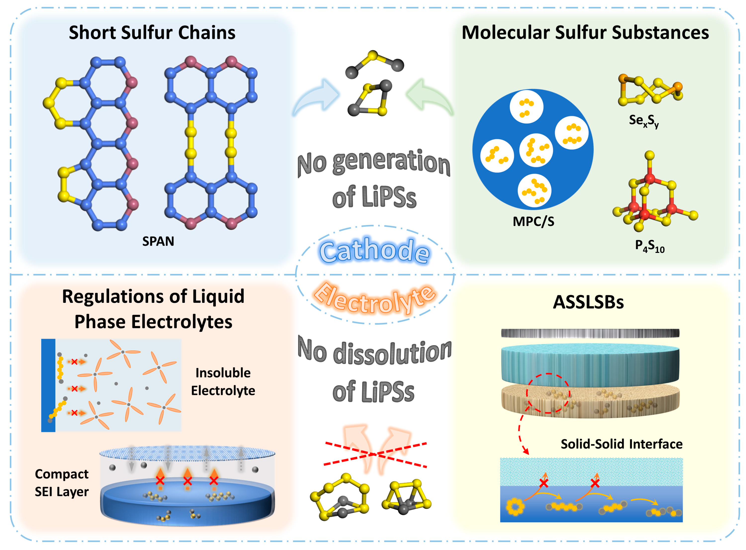
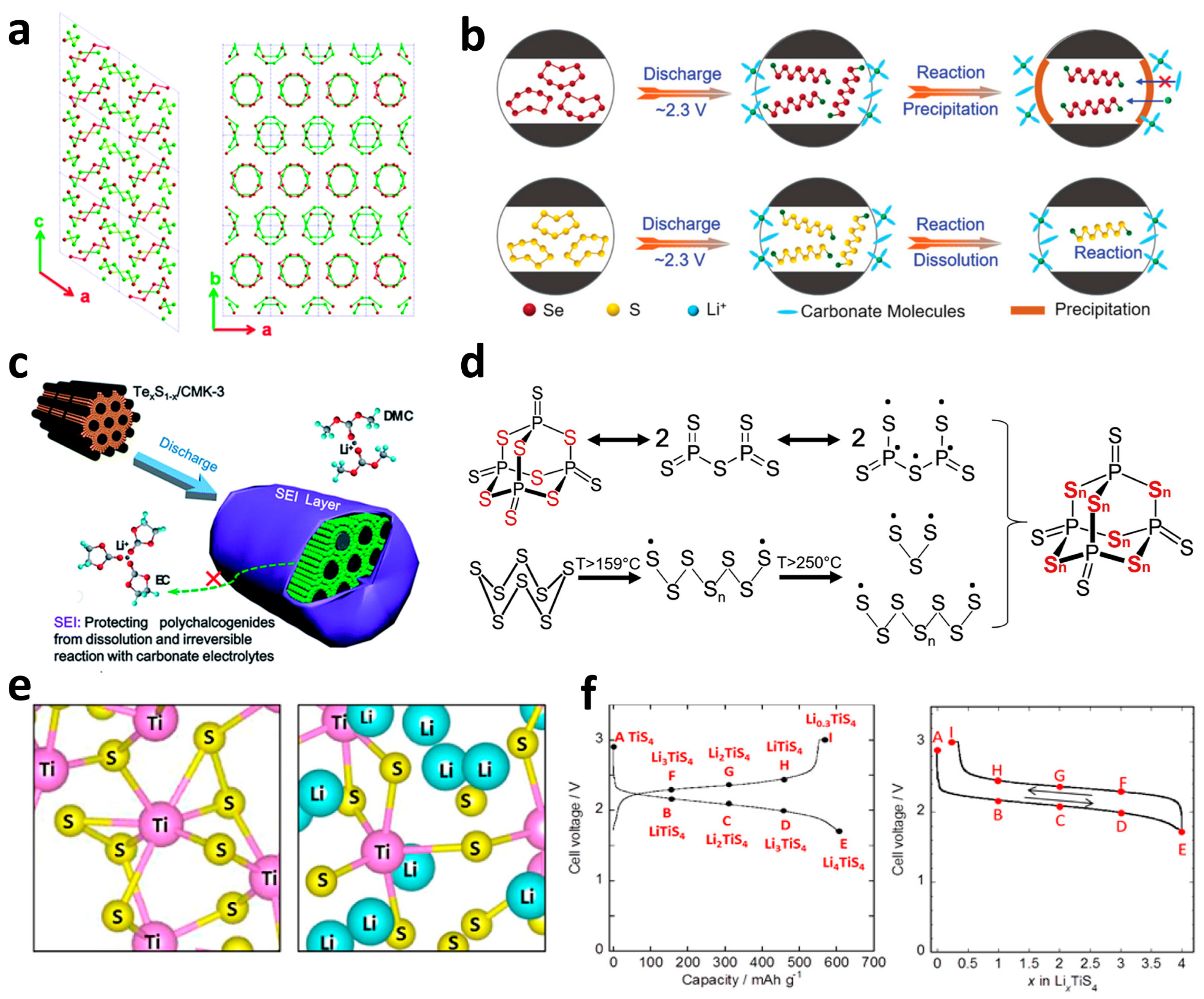
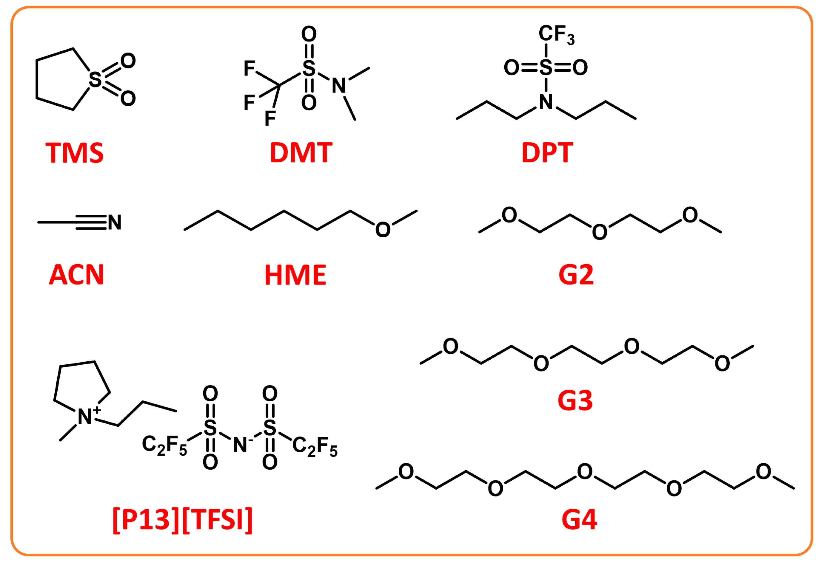
Table 1.
Summary of SPAN cathodes with different modifications.
| Sample | Sulfur Content/wt% | Electrolyte | Current Density/mA g−1 | Cycle Number—Capacity (Retention)/mAh g−1 | Rate Capability/mAh g−1 | Ref. |
|---|---|---|---|---|---|---|
| S@PAN/S7Se | 68 (S + Se) | 1M LiPF6 + EC/DMC (1:1 by volume) + 5%FEC | 1000 | 100–675 | 6 A g−1—453.5 | [55] |
| pPAN-S@GNS | 47 | 1M LiPF6 + EC/DMC (1:1 by volume) | 0.2 C | 300–604.9 (88.8%) | 10 C—~330 | [65] |
| S/DPAN/rGO | 44.76 | 1M LiPF6 + EC/DMC (3:7 by volume) | 0.2 C | 100–613.6 (92%) | 2 C—313.3 | [66] |
| S/MCPs-PAN | 52 | 1M LiPF6 + PC/EC/DEC (1:4:5 by volume) | 160 | 200–666 (84.4%) | 4 C—369.7 | [67] |
| S/rSP@SPAN | 54.5 | 1M LiPF6 + EC/DEC (1:1 by volume) | 0.1 C | 100–681.8 | 10 C—268 | [68] |
| PBD622–400 | 31.31 | 1M LiPF6 + EMC/EC/DEC (1:1:1 by volume) | 1050 | 150–250.5 | [69] | |
| PAN/PS/VGCF | 37.78 | 1M LiPF6 + EC/DEC (1:1 by volume) | 1 C | 150–341.2 | 2 C—254.6 | [70] |
| 3DHG/PS | 40.2 | 1M LiTFSI + DOL/DME (1:1 by volume) + 1% LiNO3 | 0.5 C | 800–383.3 | 5 C—198.9 | [71] |
| SeS0.7/CPAN | 33 (SeS0.7) | 1M LiPF6 + EC/DEC (1:1 by volume) | 600 | 1200–257.4 | 6 A g−1—148.5 | [74] |
| pPAN/SeS2 | 63 (SeS2) | 1M LiPF6 + EC/DMC (1:1 by volume) | 500 | 100–642.6 | 5 A g−1—446.7 | [75] |
| S0.87Se0.13/CPAN | 29.79 (S) + 10.82 (Se) | 1M LiPF6 + EC/DMC/DEC (1:1:1 by volume) | 300 | 200–401.6 | [76] | |
| SeSPAN | 60 | 1M LiPF6 + EC/DEC (1:1 by volume) | 100 | 250–402 (80%) | 2 A g−1—360 | [77] |
| Se0.06SPAN | 47.25 (Se0.06) | 1M LiTFSI + DOL/DME (1:1 by volume) + 2% LiNO3 | 200 | 500–533.9 (91.6%) | 10 A g−1—425.3 | [78] |
| Te0.04S0.96@pPAN | 47.62 | 1M LiTFSI + DOL/DME (1:1 by volume) + 0.2 M LiNO3 | 500 | 200–482.4 (87.3%) | 10 A g−1—410 | [80] |
| S/PAN/Mg0.6Ni0.4O | 38.5 | 1M LiPF6 + EC/DMC/DEC (1:1:1 by volume) | 0.1 C | 100–470.9 | 1 C—171.3 | [82] |
| CoS2-SPAN-CNT | 43.2 | 1M LiPF6 + EC/DMC/DEC (1:1:1 by volume) | 0.2 C | 100–439.8 | 2 C—288.1 | [83] |
| Co10-SPAN-CNT | 41.9 | 1M LiPF6 + EC/DMC/DEC (1:1:1 by volume) | 0.2 C | 100–586.2 | 5 C—352.8 | [84] |
Table 2.
Summary of MPC/S cathodes with different structures and performances.
| Sample | Carbon Source | Method | Pore Size/nm | Sulfur Content/% | Current Density/mA g−1 | Cycle Number—Capacity (Retention)/mAh g−1 | Ref. |
|---|---|---|---|---|---|---|---|
| S/(CNT@MPC) | D-glucose | Solvothermal-calcination | 0.5 | 40 | 0.1 C | 200–1142 | [40] |
| Sulfur-carbon sphere | Sucrose | Solvothermal-calcination | 0.7 | 42 | 400 | 500–650 | [125] |
| S/C | Sucrose | Solvothermal-calcination | 1 | 40 | 100 | 100–720 | [126] |
| C/S-50-T | Sucrose | Solvothermal-calcination | 1.7–6 | 26 | 100 | 500–860 | [127] |
| S@UMPC | D-glucose/sucrose | Solvothermal-calcination | 0.6 | 40 | 0.1 C | 150–900 | [129] |
| CS-Ex | Phenolic resin | Template method | 0.65 | 16 | 150 | 50–900 | [130] |
| FDU/S-40 | Phenolic resin | Template method | 0.46 | 40 | 500 | 170–608 | [131] |
| 100 | 400–900 | ||||||
| 400 | 500–>600 | ||||||
| SPC2 | Phenolic resin | Template method | 4 | 58.12 | 600 | 100–730 | [132] |
| CA(Ar) + Sinf | Phenolic resin | Template method | <1 | 23 | 500 | 200–990 | [134] |
| CSC-S | Coconut shells | KOH activation | 0.53 | 45.8 | 0.2 C | 100–703 (75%) | [135] |
| c-MNS/S40 | Macadamia nut shell | KOH activation | 0.6 | 41 | 0.1 C | 100–998 | [136] |
| S-PVDCDC | Polyvinylidene dichloride | Direct calcination | <1 | 40 | 260 | 200–~750 | [137] |
| S/UMC-2 | PVDF | Direct calcination | 0.55 | 37.7 | 0.1 C | 150–852 | [138] |
| KC/S | Potassium tartrate | Direct calcination | 0.49 | 42.5 | 0.1 C | 50–968 | [139] |
| S2–4/UMC-MFC | PVDF | Direct calcination | 0.55 | 37.2 | 0.1 C | 100–693 | [140] |
| MXene-bonded S2–4/UMC | PVDF | Direct calcination | 0.55 | 37.2 | 0.1 C | 200–946 | [141] |
| MPCP-S-I | ZIF-8 | Direct calcination | <2 | 43 | ~230 | 100–490 | [146] |
| C-S-3 | ZIF-8 | Direct calcination | 0.5 | 27 | 335 | 100–936 (82.6%) | [147] |
| NPCS-S50 | Ppy/ZnCl2 | Template method | <0.8 | 53 | 0.3 C | 200–1002 | [148] |
| NDMC/S | Triblock copolymer F127 + 4,4′-bipyridine | Template method | 0.57 | 28 | 0.2 C | 500–902 | [149] |
Table 3.
Summary of non-metallic sulfides and their properties of batteries.
| Cathode | Active Material Content/wt% | Electrolyte | Current Density/mA g−1 | Cycle Number—Capacity (Retention)/mAh g−1 | Rate Capability/mAh g−1 | Ref. |
|---|---|---|---|---|---|---|
| S0.94Se0.06/C | 50 | 1 M LiPF6 + EC/DMC (1:1 by volume) | 1000 | 500–910 | 20 A g−1—617 | [155] |
| S0.94Se0.06@PCNFs | 49 | 1 M LiPF6 + EC/DMC (1:1 by volume) | 100 | 100–840 | 10 A g−1—350 | [156] |
| w-SeS2/ OMC | 49 | 1 M LiPF6 + EC/DEC (1:1 by volume) | 1 C | 2000–360 | 2 C—273 | [157] |
| CMK-3/Se5S3 | 67 | 1.2 M LiPF6 + EC/DMC (1:1 by volume) + 5% FEC | 1000 | 300–609 | 6 A g−1—417 | [158] |
| Te0.1S0.9/CMK-3 | 70 | 1 M LiPF6 + EC/DMC (1:1 by volume) | 250 | 100–845 | 5 A g−1—590 | [159] |
| Li3PS4+5 | 47.1 | Li3PS4 solid electrolyte | 0.1 C | 300–329 300–565 (60 °C) | 2 C—346 (60 °C) | [161] |
| S-P2S5 | 50 | P2S5 solid electrolyte | 0.1 C | 471 | [162] | |
| P4S34/C | 40.2 | Li10GeP2S12 + Li3PS4 solid electrolyte | 200 | 180–458.5 | [163] |
Table 4.
Summary of transition metallic sulfides and their properties of batteries.
| Cathode | Electrolyte | Current Density/mA g−1 | Cycle Number—Capacity (Retention)/mAh g−1 | Ref. |
|---|---|---|---|---|
| a-NbS3 | 1 M LiPF6 + EC/DMC (1:1 by volume) | 10–281 | [164] | |
| a-TiS3/S/KB | 80 Li2S · 20P2S5 solid electrolyte | 0.064 mA cm−2 | 50–650 | [165] |
| MoS3/MWCNTs | 1 M LiTFSI + DOL/DME (1:1 by volume) + 0.1 M LiNO3 | 0.5 mA cm−2 | 200–291.7 | [166] |
| a-FeS4/C | 1.2 M LiPF6 + EC/DMC (1:1 by volume) + 5% FEC | 100 | 500–644 | [167] |
| a-TiS4 | 1 M LiPF6 + EC/DMC (1:1 by volume) | 400 | 2–500 | [168] |
| P0.4VS5.0 | 1 M LiPF6 + EC/DMC (1:1 by volume) | 0.1 C | 50–445 | [169] |
Table 5.
Summary of SSEs and their properties of batteries.
| Cathode | Anode | Electrolyte Materials | Interlayer Material | Battery Operating Temperature/°C | Electrolyte Conductivity/S cm−1 | Rate-Cycle Number-Capacity/ mAh g−1 | Ref. |
|---|---|---|---|---|---|---|---|
| S–PAN | Li | PMMA-PVdF-HFP + 1M LiPF6 in EC/DMC | 25 | 0.2 C-100-441 (88%) | [205] | ||
| PANI@C/S-280 | Li | PEO–MIL-53(Al)–LiTFSI | 80 | 4 C-1000-325 | [206] | ||
| S | Li | PEO + LiTFSI + HNT | 100 | 2.14 × 10⁻³ | 4 C-400-386 | [207] | |
| C-S | Li | PC-Li-Nafion | Li-Nafion interlayer | 70 | 2.1 × 10⁻⁴ | 1C-100-796 (89%) | [208] |
| PVDF-coated S/C | Li | PEO-LiTFSI | 55 | 0.05 mA cm−2-60–630 | [209] | ||
| SeS2 | Li | Li10GeP2S12–Li3PS4 | 25 | [210] | |||
| C/S | Li | LiBH4/SiO2 | [211] | ||||
| rGO@S-Li10GeP2S12-AB | Li | Li10GeP2S12/75%Li2S-24%P2S5-1%P2O5 | 60 | 8.27 × 10⁻³ Li10GeP2S12 | 1 C-750–830 | [212] | |
| CNT@S-Li10GeP2S12 | Li–In | Li10GeP2S12 | In foil | 25 | 8.27 × 10⁻³ | 0.1 C-200–998.6 (87.7%) | [215] |
| nano-sulfur/MWCNT-Li6PS5Cl | Li–In | Li6PS5Cl | 25 | 3.15 × 10⁻³ | 0.1 C-50–1393 | [216] | |
| PAN-S | Li | Li2S-P2S5 | 60 | 2.5 × 10⁻³ | 0.1 C-50–487 (99%) | [217] | |
| S@KBC-Li10GeP2S12-AB | Li | Li10GeP2S12 | 1 M LiFSI/PYR13TFSI IL. | 25 | 2.04 × 10⁻³ | 83.5 mA g−1-25–868 (81%) | [219] |
| Li2S-Li6PS5Cl-C | Li-In | 80 Li2S·20P2S5 | 25 | 1.3 × 10⁻³ | 50 mA g−1-60–830 | [222] | |
| 80Li2S·20LiI-VGCF | Li-In | 75 Li2S·25P2S5 | In foil | 25 | 2 C-2000-980 | [223] | |
| Li2S@C-LPS-AB | Li-In | Li7P3S11 | 60 | 1.7 × 10⁻³ | 2 mA cm−2-700–643 (93%) | [224] | |
| Li2S@NC-Li7P3S11-AB | Li-In | Li7P3S11 | 60 | 0.5 mA cm−2-100–690 (80%) | [225] | ||
| Co9S8-Li7P3S11 | Li | Li10GeP2S12/70%Li2S-29% P2S5-1%-P2O5 | 25 | 1.5 × 10⁻³ Li7P3S11 | 1.27 mA cm−2-100–421 | [227] | |
| FeS + S | Li | 77.5Li2S:22.5P2S5 | 60 | 225-900 | [228] | ||
| S/PAN | Li | MPS/PVdF-HFP/f-PMMA + 1M LiPF6 in EC/DEC | 25 | 0.2 C-100–1143 | [229] | ||
| KB–S | Li | Li1.5Al0.5Ge1.5(PO4)3 | 25 | 1.77 × 10⁻⁴ | 0.2 C-40–720 | [231] | |
| S/C | Li | FDE-LAGP | 25 | 3.2 × 10⁻⁴ | 1 C-1200-668 (73%) | [232] | |
| Li2S | Li-In | Li7P3S11 | (ACN)2-LiTFSI:HFE | 25 | 0.1 C-100–760 | [233] |
Disclaimer/Publisher’s Note: The statements, opinions and data contained in all publications are solely those of the individual author(s) and contributor(s) and not of MDPI and/or the editor(s). MDPI and/or the editor(s) disclaim responsibility for any injury to people or property resulting from any ideas, methods, instructions or products referred to in the content. |
© 2022 by the authors. Licensee MDPI, Basel, Switzerland. This article is an open access article distributed under the terms and conditions of the Creative Commons Attribution (CC BY) license (https://creativecommons.org/licenses/by/4.0/).
Share and Cite
MDPI and ACS Style
Yi, Y.; Hai, F.; Guo, J.; Tian, X.; Zheng, S.; Wu, Z.; Wang, T.; Li, M. Progress and Prospect of Practical Lithium-Sulfur Batteries Based on Solid-Phase Conversion. Batteries 2023, 9, 27. https://doi.org/10.3390/batteries9010027
AMA Style
Yi Y, Hai F, Guo J, Tian X, Zheng S, Wu Z, Wang T, Li M. Progress and Prospect of Practical Lithium-Sulfur Batteries Based on Solid-Phase Conversion. Batteries. 2023; 9(1):27. https://doi.org/10.3390/batteries9010027
Chicago/Turabian StyleYi, Yikun, Feng Hai, Jingyu Guo, Xiaolu Tian, Shentuo Zheng, Zhendi Wu, Tao Wang, and Mingtao Li. 2023. "Progress and Prospect of Practical Lithium-Sulfur Batteries Based on Solid-Phase Conversion" Batteries 9, no. 1: 27. https://doi.org/10.3390/batteries9010027
Note that from the first issue of 2016, this journal uses article numbers instead of page numbers. See further details here.