Article

Co-Sintering of Li1.3Al0.3Ti1.7(PO4)3 and LiFePO4 in Tape-Casted Composite Cathodes for Oxide Solid-State Batteries

1
Fraunhofer Institute for Ceramic Technologies and Systems IKTS, 01277 Dresden, Germany
2
Inorganic Non-Metallic Materials, Technical University Dresden, 01062 Dresden, Germany
*
Author to whom correspondence should be addressed.
Batteries 2023, 9(11), 543; https://doi.org/10.3390/batteries9110543
Submission received: 18 August 2023 / Revised: 17 October 2023 / Accepted: 30 October 2023 / Published: 2 November 2023
(This article belongs to the Special Issue Recent Progress in All-Solid-State Lithium Batteries)

Abstract

:
Solid-state batteries (SSBs) with Li-ion conductive electrolytes made from polymers, thiophosphates (sulfides) or oxides instead of liquid electrolytes have different challenges in material development and manufacturing. For oxide-based SSBs, the co-sintering of a composite cathode is one of the main challenges. High process temperatures cause undesired decomposition reactions of the active material and the solid electrolyte. The formed phases inhibit the high energy and power density of ceramic SSBs. Therefore, the selection of suitable material combinations as well as the reduction of the sintering temperatures are crucial milestones in the development of ceramic SSBs. In this work, the co-sintering behavior of Li1.3Al0.3Ti1.7(PO4)3 (LATP) as a solid electrolyte with Li-ion conductivity of ≥0.38 mS/cm and LiFePO4 with a C-coating (LFP) as a Li-ion storage material (active material) is investigated. The shrinkage behavior, crystallographic analysis and microstructural changes during co-sintering at temperatures between 650 and 850 °C are characterized in a simplified model system by mixing, pressing and sintering the LATP and LFP and compared with tape-casted composite cathodes (d = 55 µm). The tape-casted and sintered composite cathodes were infiltrated by liquid electrolyte as well as polyethylene oxide (PEO) electrolyte and electrochemically characterized as half cells against a Li metal anode. The results indicate the formation of reaction layers between LATP and LFP during co-sintering. At Ts > 750 °C, the rhombohedral LATP phase is transformed into an orthorhombic Li1.3+xAl0.3−yFex+yTi1.7−x(PO4)3 (LAFTP) phase. During co-sintering, Fe3+ diffuses into the LATP phase and partially occupies the Al3+ and Ti4+ sites of the NASICON structure. The formation of this LAFTP leads to significant changes in the electrochemical properties of the infiltrated composite tapes. Nevertheless, a high specific capacity of 134 mAh g−1 is measured by infiltrating the sintered composite tapes with liquid electrolytes. Additionally, infiltration with a PEO electrolyte leads to a capacity of 125 mAh g−1. Therefore, the material combination of LATP and LFP is a promising approach to realize sintered ceramic SSBs.

Graphical Abstract

1. Introduction

Lithium-ion batteries (LIBs) have become one of the largest energy storage technologies for mobile applications. In particular, LIBs are used in automobiles due to their high power and energy density, durability and moderate safety in comparison with other storage concepts. Despite all this, ever higher demands are being placed on modern energy storage technologies, such as higher charging velocity and improved safety, so new concepts have to be developed [1]. In addition, alternative applications with particularly high safety requirements or extended temperature ranges are also being developed [2,3,4]. One of the most promising concepts are solid-state batteries [5], in which the flammable liquid electrolyte in LIBs is substituted with a non-flammable solid electrolyte [6]. Another advantage is that the dense microstructure of the solid electrolyte prevents the formation of dendrites at the interface between anode and electrolyte [7]. Both features increase the safety of solid-state batteries compared with conventional LIBs. The energy density is particularly increased by the integration of the lithium metal anode, so that energy densities of >350 Wh/kg are possible [8]. Since the solid electrolyte has a higher temperature stability than many conventional electrolytes, the range of applications expands, especially for high temperatures.
The most prominent material classes of solid electrolytes include polymers [9,10,11], oxides [12,13], thiophosphates (sulfides) [14,15] and halides [16,17]. Each of these differ in their properties regarding ionic conductivity, (electro)-chemical stability to active materials, temperature stability, processability and manufacturing costs. For example, polymer electrolytes can be used for process technology and show good thermal plasticity for casting thin films [18]. However, high ionic conductivities of 10−4–10−3 S/cm are only achieved at temperatures between 60 and 80 °C [19]. Other solid electrolyte classes, such as thiophosphates or halides, show ionic conductivities of 24 mS/cm [20] that are higher than conventional liquid electrolytes even at room temperature. However, anhydrous synthesis of thiophosphates and cost-effective scaling under inert atmosphere remain major challenges [21]. Further hybrid cell concepts combine different solid electrolyte classes and can thus increase the ionic conductivity at room temperature (polymers/oxides) [22], as well as reducing the cell pressure (thiophosphates/oxides) [23].
In comparison, oxide solid electrolytes are already produced on a technical scale with several kg per batch [24,25]. These materials indicate high thermal and mechanical stability [26] as well as high ionic conductivities of up to 1.3 mS/cm at room temperature [27]. Electrochemical stability over a wider potential range of up to 4.2 V is also found [28]. The most common oxide electrolytes are garnet (Li7−xLa3Zr2−xMxO12, LLZO) [13], perovskite (Li3xLa2/3−xTiO3, LLTO) [29] and NASICON-like structured phosphates (Li1+xAlxTi1−x(PO4)3, LATP) [27]. LLZO, for example, is one of the few solid electrolytes that is compatible with metallic lithium [30]. As a thin ceramic layer, this solid electrolyte might be used as a separator between the cathode and Li metal anode. Phosphate solid electrolytes, such as LATP, are limited to a potential range > 2.17 V vs. Li/Li+ due to Ti4+/3+ reduction [28]. Therefore, LATP is particularly discussed as a solid electrolyte in the cathode (named as catholyte) with a high oxidation stability. One of the biggest challenges of oxide solid electrolytes is the densification and sintering of the microstructure by high-temperature treatment. During this sintering step, individual particles grow together by diffusion and form Li-ion conducting paths along the grain core and grain boundaries [31]. Whereas a dense structure of only one material is formed in the separator during sintering (that of the solid electrolyte), the composite cathode consists of at least a lithium-storing active material (e.g., LiCoO2, LiMn2O4 or LiFePO4), an ion-conducting solid electrolyte and an electron conductor. The solid electrolyte must form a dense percolating network around the active material particles that enables the transport of Li+ from the separator to the lithium-storing active material. However, the high sintering temperatures of between 700 and 1200 °C favor the unwanted decomposition reactions of the materials, which destroy the crystal structure and thereby the functionality of the ion conductive solid electrolyte and active material. The compatibility between active materials (e.g., LiCoO2, LiMn2O4 or LiFePO4) and LATP during co-sintering has been comparatively studied [32,33,34,35]. The decomposition reaction between oxide active materials and LATP starts at a co-sintering temperature T > 500 °C, which is significantly lower than the necessary sintering temperature of the pure solid electrolyte of Ts = 700–1000 °C [12,36,37].
Recently, a detailed analysis of the decomposition mechanisms in ceramic composite cathodes was performed for the co-sintering of LATP and LiNi0.6Mn0.2Co0.2O2 (NCM622) [38]. The decomposition of the solid electrolyte and active material is attributed to the diffusion of Li2O resulting in the depletion of lithium in the active material and the formation of Li3PO4 in the solid electrolyte as a thermodynamical driving force. Similar observations are also shown by further analysis on the co-sintering of layered-oxide LiMO2 or spinel-structured LiM2O4 (M = Co, Mn, Ni) with phosphate solid electrolytes [32,33,34,39]. Li et al. [40] presented the reduction of the decomposition reactions during pressure-supported sintering with LATP by introducing a protective layer on the LiCoO2 active material particles. As a result, initial capacities of 146 mAh g−1 could be achieved after co-sintering at 750 °C. Additionally, initial capacities of 107 mAh g−1 were obtained with a composite cathode of LiCoO2 and LATP with B2O3 as a sintering additive [41]. In fast co-sintering of the composite cathode, the reaction time was limited to 2 min at 640 °C and resulted in a thinner reaction layer between the active material and the solid electrolyte, which maintained the functionality of the composite cathode. Nevertheless, co-sintered solid-state batteries with LATP solid electrolytes require a liquid or polymer auxiliary electrolyte to achieve high ionic conductivity within the cathode [35]. In contrast, the first concepts of ceramic all solid-state batteries with LLZO solid electrolytes are already known. Capacities of up to 110 mAh g−1 are achieved after the co-sintering of LLZO-LiCoO2 [42,43,44,45,46] and 122 mAh g−1 for the co-sintering of LLZO-Li3BO3-NCM811 [47] without an additional auxiliary electrolyte.
All presented solid-state battery concepts with oxide electrolytes pursue the approach of reducing the necessary sintering temperature by pressure-assisted sintering techniques or addition of additives so that the undesired decomposition reactions of the materials do not occur during sintering. The selection of suitable material combinations for the active material and solid electrolyte may significantly increase the compatibility during co-sintering. High chemical and structural similarities between the active material and solid electrolyte are expected and might result in lower decomposition effects during co-sintering. Therefore, LATP, as a phosphate-based solid electrolyte, should have high compatibility with phosphate active materials, such as LiFePO4. Based on the crystal structures of the active material (olivine) and solid electrolyte (NASICON), both materials have comparable PO43− anion concentrations of 23–24 mmol/cm3. Paolella et al. [48,49] describe a pressure-supported (hot pressing) sintering of a 30 µm-thick composite cathode made from LiFePO4 and Li1.5Al0.5Ge1.5(PO4)3 (LAGP) on a 60 µm-thick LAGP separator layer. By introducing an auxiliary electrolyte (poly-ethylen oxid (PEO) or ionic liquid) between the separator and lithium metal anode, capacities of up to 133 mAh g−1 at 80 °C are achieved. However, it is also shown that the necessary relative densities and ionic conductivities within the composite cathode can only be achieved with pressure-assisted sintering techniques. In addition, with phosphate solid electrolytes containing elements with reduction potential such as Ti4+/3+, auxiliary electrolytes (polymer, ionic liquid, liquid electrolyte) must be used to prevent direct contact between the separator and lithium metal anode, to avoid unwanted degrading electrochemical reactions. Due to an infiltration of the auxiliary electrolyte into the open porosity of the sintered solid electrolyte, lithium-ion migration is not necessarily restricted to the LATP phase.
In the present study, the reaction mechanism of LiFePO4 as a storage material and Li1.3Al0.3Ti1.7(PO4)3 as a solid electrolyte during co-sintering at different temperatures is investigated. Based on these results, the limiting parameters for the pressureless sintering of tape-casted composite cathodes are established. The sintered tapes are infiltrated with conventional liquid or polymer electrolytes and electrochemical cell tests are performed to measure the resulting capacity of LFP after heat treatment.

2. Materials and Methods

2.1. Preparation of LATP-LFP Pellets

The powder mixtures were prepared by using commercial C-LiFePO4 (Clariant Life Power® PA30, Muttenz, Switzerland) and LATP synthesized via the sol-gel method. A detailed description of the oxide–solid electrolyte synthesis and the ionic conductivity of conventionally sintered LATP of 3.8 × 10⁻⁴ S/cm is given by Waetzig et al. [12]. The solid electrolyte and active material were suspended in ethanol with a weight ratio of 50:50 and mixed in a planetary mill (Pulverisette 7 Fritsch GmbH, Idar-Oberstein, Germany) using ZrO2 milling pots. A rotational speed of 200 rpm for 30 min with ZrO2 balls was used for this purpose. The solvent of the suspension was removed, and the powder mixture was sieved.
The investigations of the reactivity were carried out on sintered composite cylinders. For this purpose, the powder mixtures were uniaxially pressed using 5 kN to form tablets with 8 mm diameter and 4 mm height. The tablets were sintered on Al2O3 substrates in a muffle furnace under N2 atmosphere with 3 K/min to a temperature between 650 and 850 °C for a dwell time of 30 min.

2.2. Characterization of LATP-LFP Pellets

The densification behaviour during sintering was investigated using an optical dilatometer (EM301, Hesse Instruments, Osterode am Harz, Germany). For this, cylinders with 2 mm diameters and heights made from LATP, LFP and the composite system LATP-LFP were uniaxially pressed using 0.5 kN. Then, the sintering behaviour were determined by heating to a temperature of 1000 °C with a 5 K/min ramp under flowing N2, and the silhouette was imaged every 10 s. Based on the silhouette, the linear shrinkage of the samples was calculated using EMI III software (Version 3.1.6-1, Hesse Instruments, Germany). For crystallographic phase analysis, X-ray powder diffraction (XRD, D8 Advance Bruker, Billerica, MA, USA) was performed. Therefore, the sintered samples were mortared and measured with Cu Kα radiation. The diffraction was detected in the range 10° < 2θ < 70°, with a step width of 0.02°. A qualitative analysis of the phases was performed using DIFFRAC.SUITE EVA (Version 6.1.0.4) software. The microstructure of the sintered samples was imaged with field-emission electron beam microscopy (FESEM, NVision 40 Zeiss, Oberkochen, Germany). The sintered tablets were embedded in resin and cross sections were cut by dry grinding and polishing. Energy dispersion X-ray (EDX) mappings were performed using an EDX detector from Oxford Instruments (Abingdon, UK) for imaging the elemental distribution (without Li). Thermogravimetric analysis linked with mass spectrometry was performed in an STA 429 CD by Netzsch GmbH (Selb, Germany). For this purpose, in an Al2O3 crucible, 100 mg of sample was heated to a temperature of 1000 °C at 5 K/min within the flowing N2. The reaction product was characterized by QMG422 (Balzers, Liechtenstein) mass spectroscopy and the m/z ratio of 44 was determined as the CO2 signal. For calculating the density after sintering, the geometry of the sintered samples was determined by measuring the diameter, height and mass of the samples.

2.3. Tape Casting of LATP-LFP Sheets

For the tape casting of the composite sheets, powder mixtures of 62 wt.% LFP and 38 wt.% LATP (66/34 vol.%) were prepared according to the above-described milling parameters. For the preparation of the casting slurry, an ethanol/methyl ethyl ketone (MEK) azeotrope as solvent, a dispersant (polyester/polyamide copolymer), plasticizers (typ I and typ II) and a polyvinyl-butyral-based binder was mixed with LATP and LFP powder. The slurry was homogenized by stirring overnight and cast into green films using the doctor blade method. The dried green film was isostatically laminated at a temperature of 60 °C and cut out to form round samples with 18 mm diameters. Burnout of organic binders/additives and sintering of the composite cathodes was performed under flowing N2. The green films were sintered between two porous Al2O3 substrates. The samples were heated with a ramp of 0.5 K/min to 400 °C and had a 3 h dwelling time for debinding. Subsequent sintering was carried out with a heating rate of 3 K/min at different temperatures between 650 and 850 °C for 1 h.
All the following handlings were performed in an argon-filled glove box with monitored H2O and O2 contents (<1 ppm).

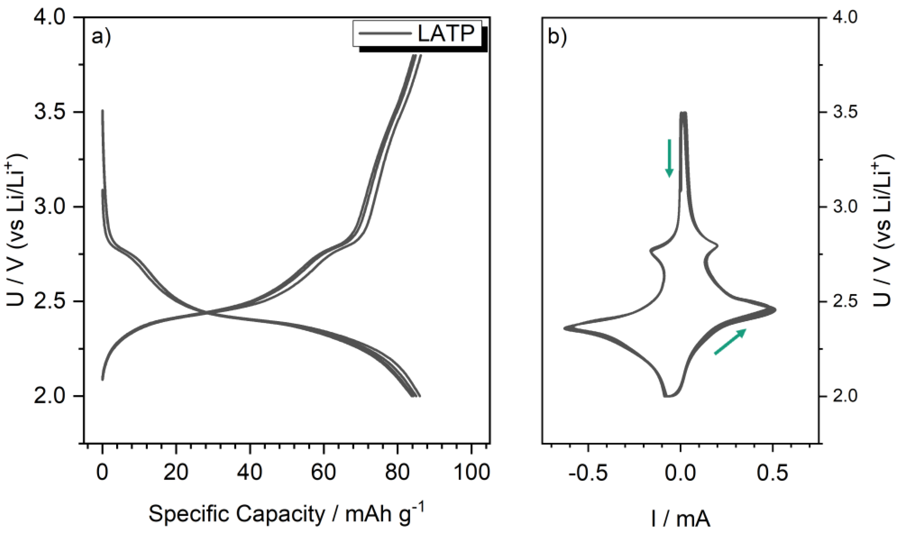
2.4. Electrochemical Characterization of LATP-LFP Sheets

For reference measurements, carbon-coated LATP powder was prepared as a conventional electrode. For this, 600 mg LATP, 77 mg conductive carbon (Super C65, Timcal Graphite and Carbon, Bodio, Switzerland), 1.5 g of a 5 wt.% PVDF in NMP solution and 1.5 g additional NMP (Sigma Aldrich, St. Louis, MO, USA) were mixed in a centrifugal mixer. The slurry was casted on aluminium foil using a 500 µm doctor blade. The electrode was dried at 80 °C overnight an in vacuum. PEO-LiTFSI (abbreviated as PEO separator) separator films were prepared by dissolving 1 g PEO 400,000 (Sigma Aldrich) and 0.33 g LiTFSI (99%, IoLiTec Ionic Liquid Technologies, Heilbronn, Germany) in 16 g NMP at 75 °C. The solution was casted into a Petri dish (Teflon) and the solvent was allowed to evaporate at 80 °C. The film was removed from the dish and die-cut to a 20 mm diameter. The samples showed an ionic conductivity of 5∙10−4 S/cm at 60.0 °C.
Electrochemical testing was performed either in 2032-coin cells or EL-Cell ECC-Std cells. The cells for liquid electrolyte characterization were assembled using a lithium anode, a Whatman glass fiber separator infiltrated with 1 M solution of LiPF6 in ethylene carbonate/diethylene carbonate (1:1 mixture, E-Lyte Innovations, Kaiserslautern, Germany) and either a conventional pristine LATP electrode or a sintered LATP-LFP composite. For solid electrolyte cells, the infiltrated glass fiber separator was substituted with a PEO film.
Electrochemical tests were performed using a Biologic VMP 3 potentiostat and the software EC-lab v. 11.43 (BioLogic Science Instruments, Seyssinet-Pariset, France). After assembly, the cells were placed in temperature-controlled cabinets and allowed to settle for 24 h (liquid electrolyte cells: 45.0 °C; PEO cells: 60.0 °C). Cycling was performed in constant-current mode without a constant voltage phase with a charging threshold of 3.8 V for LFP characterization and discharging thresholds of 3.0 V for characterization of LFP and 2.0 V for LATP as well LATP-LFP reaction products. Impedance spectra were collected in a frequency range from 200 kHz to 100 mHz using a p-p amplitude of 25 mV.

3. Results

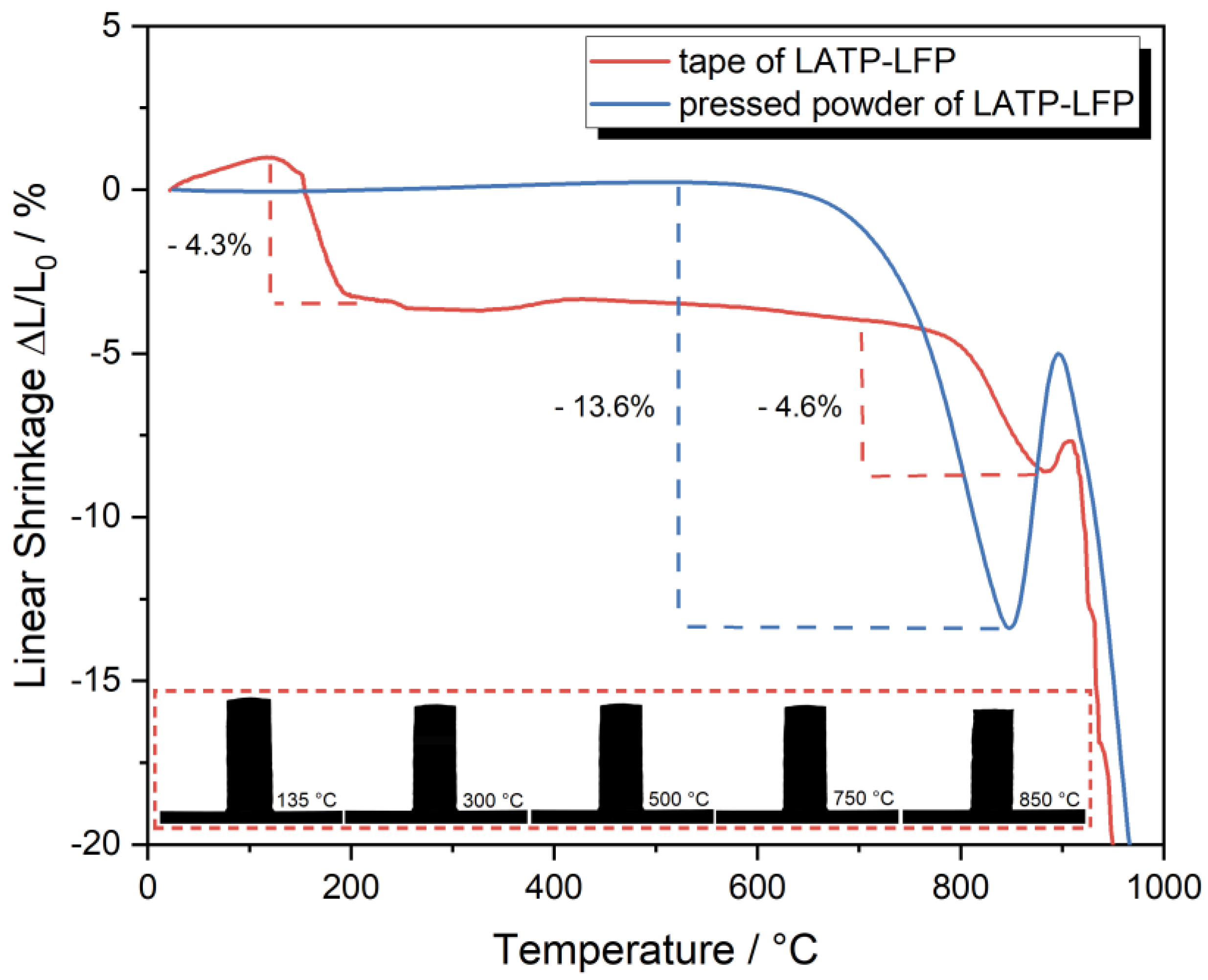
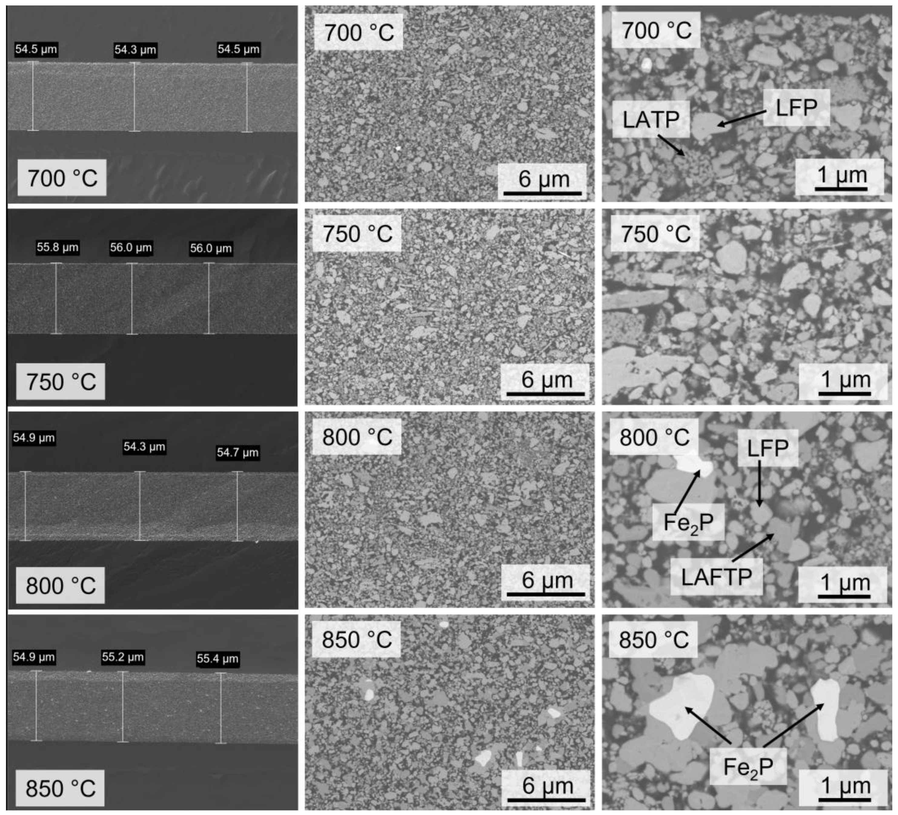
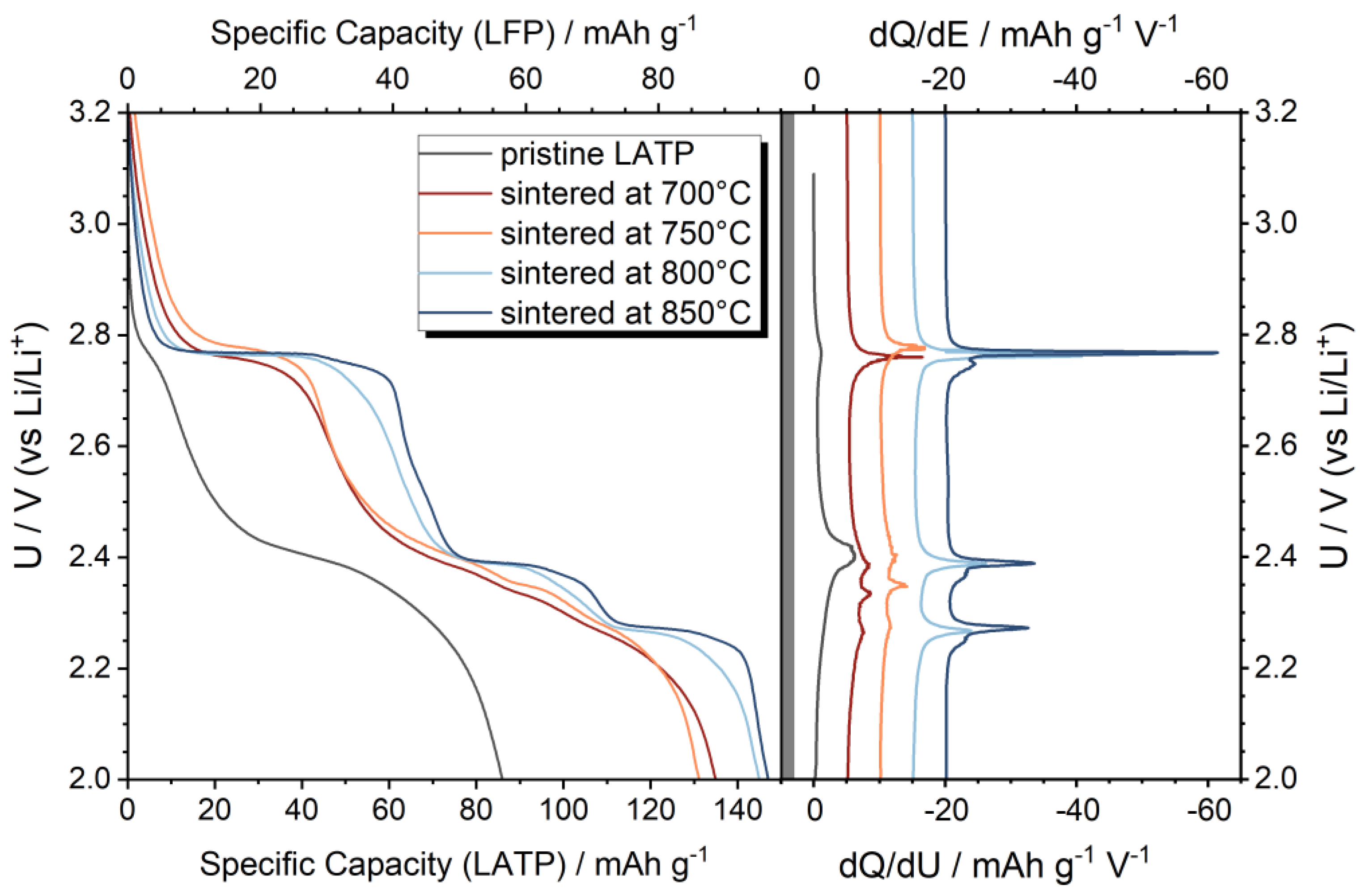
3.1. Characterization of LATP-LFP Pellets during and after Heat Treatment

The sintering of the solid electrolyte and the composite cathode are the major challenges of oxide solid-state batteries [50]. Homogeneous shrinkage of the composite must occur at lower temperatures than the formation of decomposition reactions between the components. Therefore, the sintering behavior of the binary mixture of Li1.3Al0.3Ti1.7(PO4)3 (LATP) and C-LiFePO4 (LFP) was studied using optical dilatometry (Figure 1). The shrinkage behavior of pristine LATP under a N2 atmosphere indicates a necessary sintering temperature of 1000–1100 °C for this solid electrolyte (Figure S1). The shrinkage starts at a sintering temperature Ts > 800 °C and achieves a maximum shrinkage of −11% at 1040 °C. In further investigations, an ionic conductivity for conventionally sintered LATP of 3.8 × 10⁻⁴ S/cm was achieved and for pressure-assisted sintering an ionic conductivity of ~1 × 10⁻³ S/cm was reached [12,37]. The sintering temperature can be reduced to Ts ~ 800 °C by adding sintering aids without a reduction in the ionic conductivity [36].
In comparison, the pure LFP has a low shrinkage of <−1% up to a sintering temperature Ts of 900 °C. At Ts > 900 °C, a rapid increase in linear shrinkage indicates gas and bubble formation at the sample surface. The expansion might be correlated with the decomposition reactions of the carbon coating. Raising the temperature to Ts > 940 °C results in the melting of LFP [51], which limits the temperature range for using this active material.
In contrary to the pristine LATP and the pure LFP active material, the LATP-LFP mixture exhibits shrinkage above 600 °C. A maximum linear shrinkage of −14% is reached at 810 °C. When increasing the sintering temperature to Ts > 810 °C, an expansion of the composite begins. Consequently, bubbles are formed on the sample surface, which causes inhomogeneous silhouette formation during dilatometry and fluctuation of the shrinkage curve. An explanation for the volume expansion will be given later in combination with the phase and microstructure analysis.
In addition to the shrinkage curve by dilatometry, the pressed LATP-LFP samples were sintered under a N2 atmosphere in a furnace. The relative densities of these LATP-LFP bulk samples after sintering between 700 and 850 °C are presented on the right Y axis and increase with higher sintering temperatures (Figure 1). At Ts = 850 °C, a maximum relative density of 91 ± 1% is reached. Although dilatometry already exhibits an expansion at this temperature, the sintered bulk samples still have a high relative density of >90% at Ts > 800 °C.
The thermal behavior of the LATP-LFP mixture during heating was investigated by thermogravimetry (TG) with coupled mass spectrometry (MS) (Figure 2). Further TG-MS data for pristine LATP, LFP and the LATP-LFP mixture are given in Figures S2–S4. This temperature-dependent characterization allows us to identify the critical temperatures of decomposition reactions and obtain qualitative information about the reaction products in the gas phase. LFP does not show any significant loss of mass up to a temperature of 800 °C. At higher temperatures of up to 1000 °C, the mass decreases to 95.9%. Further TG-MS investigations show that CO2+, O+ and C+ are detectable. Therefore, it can be assumed that decomposition of the carbon coating occurs at T > 800 °C and that this is correlating with the expansion during sintering detected by dilatometry.
For LATP, a two-step mass loss of −2% is observed up to a temperature of 500 °C. This can be attributed to the release of water. Another mass loss of −0.5% between 650 and 900 °C is related the release of CO2+ and seems to correlate with the decomposition of carbonates on the surface of the LATP particles. In comparison with the pure materials, the LATP-LFP mixture also shows a two-step mass loss of −1% up to a temperature of 500 °C like LATP. Above T > 600 °C, there is a continuous mass loss, so that at 1000 °C only 97.2% of the initial mass is observed. The mass loss at high temperatures also correlates with the release of CO2. Based on the TG-MS characterization, the shrinkage behavior of LATP, LFP and LATP-LFP may be interpreted more accurately. Due to the decomposition of the carbon coating of the active material and carbonate at the LATP surface, CO2 is released. The gas formation prevents homogeneous shrinkage of LATP-LFP and leads to expansion of the samples at T > 810 °C. In addition, an oxygen source must be present in the LATP-LFP for the decomposition of the carbon coating to form CO2. Based on a modified Ellingham diagram, the release of O2 during sintering of LiFePO4 in a reducing atmosphere is already described in literature [52,53]. This results in the stepwise formation of pyrophosphates (P2O74−), metaphosphates (PO3) and finally phosphides (P3−). During this decomposition LiPO3 and Li4P2O7 are formed. The low melting points of LiPO3 (604 °C) and Li4P2O7 (876 °C) [54,55] might induce the liquid-phase sintering of LATP-LFP, which explains the shrinkage at Ts < 810 °C. Therefore, the TG-MS measurements illustrate that the decomposition of the coated LFP particles limits sintering to Ts < 810 °C.
In Figure 3, the X-ray powder diffraction patterns of co-sintered LATP-LFP for identification of the phase formation are shown. Further analyses of the temperature stability of the pure substances (LATP and LFP) are given in Figures S5 and S6. At a low sintering temperature of Ts = 700 °C, only the crystalline phases of LFP and LATP are detectable. The signal intensities of the active material and solid electrolyte decrease slightly with increasing sintering temperature, so that the first decomposition reactions of the components are assumed to occur at Ts > 700 °C. Newly formed crystalline phases do not appear, so amorphous intermediate products might be formed. At high sintering temperatures of Ts > 750 °C, the reflection intensities of LATP decrease rapidly. This clearly indicates the major decomposition of the solid electrolyte. In contrast, the reflection intensities of LFP decrease less than those of LATP, which indicates a higher thermal stability of the active material during co-sintering. Moreover, new crystalline phases at Ts > 750 °C can be detected, which are assigned to Li1.3+xAl0.3−yFex+yTi1.7−x(PO4)3 (LATFP) and Fe2P2O7. Small amounts of AlPO4 and Li4P2O7 are already detectable at Ts > 650 °C. Nevertheless, increased Li4P2O7 reflex intensity is detectable after sintering at Ts = 800 °C. Moreover, the X-ray powder diffraction of pure LATP sintered under inert conditions also indicates the formation of Li4P2O7 at Ts > 800 °C (Figure S5). The formation of the pyrophosphates Li4P2O7 and Fe2P2O7 may explain the release of oxygen during co-sintering, which has already been discussed in the TG-MS results. In this process, amorphous Li4P2O7 with a low melting point seems to act as a sintering aid and improves the thermal shrinkage of LATP-LFP by liquid-phase sintering [55]. Moreover, the formation of Li1.3+xAl0.3−yFex+yTi1.7−x(PO4)3 (LAFTP) must be associated with the oxidation of Fe2+ to Fe3+ via the released oxygen. Due to the comparable ionic radii [56] of Al3+ (0.535 Å), Ti4+ (0.605 Å) and Fe3+ (0.645 Å), substitutions of Fe3+ on the Al3+ and Ti4+ sites of the NASICON structure are possible. The substitution of larger Fe3+ ions into the NASICON structure seems to be thermodynamically preferable, resulting in the formation of Li1.3+xAl0.3−yFex+yTi1.7−x(PO4)3. To maintain charge neutrality, the substitution of Ti4+ by Fe3+ requires the incorporation of additional Li+. Moreover, smaller Al3+ ions are substituted by larger Fe3+ ions, resulting in the formation of AlPO4. In the literature, different structures of Li1+zMzTi2−z(PO4)3 (M = Al3+, Fe3+, In3+) [57,58,59,60] are described independent of the substitution fraction y (y < 0.6 rhombohedral NASICON R 3 ¯ c; 0.6 < y < 1.1 orthorhombic Pbca and y > 1.1 orthorhombic Pbna). High ionic conductivities are only detected in the NASICON structure of Li1+xAlxTi2−x(PO4)3 with a low substitutional fraction x < 0.5, whereas the orthorhombic structures with x > 0.5 result in lower ionic conductivity of the solid electrolyte [61,62,63]. Here, X-ray diffraction indicates the presence of orthorhombic Li1.3+xAl0.3−yFex+yTi1.7−x(PO4)3 with 0.3 < x + y < 0.8 (Pbca structure). Therefore, increased diffusion of Li+ and Fe3+ into the solid electrolyte phase must have occurred during co-sintering, which could have an impact on the ionic conductivity and storage capacity within the composite cathode. However, a detailed analysis of the ionic conductivity in the LATP-LFP pellet is challenging. The ionic conductivity is overlapped by the electrical conductivity of the composite (e.g., C-coating). The effects cannot be clearly separated from each other, so that a detailed analysis of the ionic conductivity is only possible by further introduction of electrically insulating and ionically conductive interlayers. Due to the element diffusion that occurs and the probably associated reduction in ionic conductivity, the maximum sintering temperature should be limited to <750 °C to avoid the phase transition from rhombohedral LATP to orthorhombic LAFTP. Moreover, further amorphous phase formations might occur, which cannot be detected by X-ray powder diffraction but might influence the charge transfer at the interface between the active material and solid electrolyte.
To enable an unhindered Li+ ion transition between the solid electrolyte and the active material, the two components not only have to be chemically compatible and not react with each other during co-sintering but also a percolating Li-ion conducting system for the solid electrolyte around the active material must be formed. Cracks along the interface must be prevented and reaction zones minimized. FESEM/EDX images of the LATP-LFP bulk samples sintered at different temperatures are shown in Figure 4 and Figure S4. LiFePO4 with a high Fe content is indicated as light grey and LATP with a high Ti content is indicated as dark grey. After co-sintering at 750 °C, the LATP solid electrolyte is already partially densified. Larger coherent LATP particles of up to 5 µm are visible. With higher sintering temperatures, the LATP densification increases, resulting in a dense microstructure for the solid electrolyte after co-sintering at 850 °C. In contrast to LATP, the active material phase has a sub-µm particle size. These small particles remain as separate phases during co-sintering at 750 and 800 °C, which do not cause any densification effects. It is evident that improved sintering behavior occurs with particles of the same phase (LATP-LATP or LFP-LFP). In contrast, less heterogeneous interfaces are formed between the active material and the solid electrolyte. In particular, the C-coating of the active materials seems to inhibit densification with the solid electrolyte. At a high sintering temperature of 850 °C, enlarged pores are increasingly observed that can be attributed to the decomposition reaction of the C-coating via gas formation. The pore formation prevents the percolation of the active material through the solid electrolyte and thus might limit possible Li+ conduction paths. Along the Ti-rich solid electrolyte phases, elongated crystals are formed, which may be attributed to the orthorhombic Pbca structure of Li1.3+xAl0.3−yFex+yTi1.7−x(PO4)3. Catti et al. [57] describe an increase in the lattice parameters and an enlarged unit cell volume when the substitution fraction x is higher, which is attributed to the incorporation of the larger Fe3+ ions in the NASICON structure. The diffusion behavior of the ions is estimated by EDX mapping (Figure S7) after co-sintering at 850 °C. At the interface of LATP and LFP, a significant diffusion of Fe into the solid electrolyte phase is evident. Although Al is still detectable in the solid electrolyte phase, noticeable separations of AlPO4 are visible, which could be caused by the displacement of the smaller Al3+ ions by Fe3+. Only a small amount of additional diffusion of Ti from the solid electrolyte into the active material is observed. Consequently, the diffusion behavior of the metal ions is consistent with the newly formed crystal phases at high sintering temperatures.

3.2. Sintering of Tape-Casted Composite Cathodes

In contrast to the binary model system, the tape-casted composite cathodes consist of further components, such as a binder and a plasticizer. These are required for slurry manufacturing to produce thin green films via the tape casting process (doctor blade coating). During the temperature treatment of the tapes, organic additives must be burned out. Compared with the pressed powders, the debinded tapes consist of a varied LATP-LFP ratio and a lower green density, so that a different sintering behavior occurs during heat treatment. Figure 5 shows the shrinkage behavior of the LATP-LFP tape with organics and in comparison with the pressed powder without any additional binder. Both samples have a comparable LATP-LFP (62/38 wt.%; 66/34 vol.%) ratio.
The densification of the LATP-LFP powder is like the qualitative curve described above. The densification occurs between 650 and 850 °C and corresponds to a linear shrinkage of −13.6%. At temperatures T > 850 °C, expansion of the sample occurs and the described decomposition reactions take place. In contrast, the LATP-LFP tape (with binder) indicates an initial volume contraction between 135 and 300 °C of −4.3%. This is mainly due to the debinding process under an inert atmosphere forming H2O and CO2. Unlike the pressed powder mixture, shrinkage of the LATP-LFP tape occurs only at higher temperatures > 750 °C. Up to a sintering temperature of 880 °C, a linear shrinkage of −4.6% is determined. Therefore, the shrinkage of the LATP-LFP tape occurs at higher temperatures with lower densification. Possible reasons for this are the lower green density of the debinded LATP-LFP tape and incomplete debinding during heat treatment in the N2 atmosphere, whereby carbon residues on the particle surfaces inhibit the sintering. At sintering temperatures > 880 °C, expansion effects and rapid gas/porosity formation occur in the LATP-LFP tapes. Additional melting effects occur at T > 900 °C, which also limit the sintering temperature profile.
The microstructure analysis of the sintered LATP-LFP tapes in cross-sectional images show a constant thickness of 55 ± 1 µm independent of the sintering temperature (Figure 6). Based on the FESEM images, a densification of the microstructure is not recognizable after sintering between 700 and 850 °C. The open, porous structure is therefore retained and no percolation of the Li-ion conducting solid electrolyte is formed around the active materials. A coarsening of the LATP particles can be observed with increasing temperatures. Thus, various smaller LATP agglomerates are visible at 700 °C. After sintering at 800 and 850 °C, these agglomerates are sintered together to form larger particles without forming a macroscopic Li-ion conducting network. The formation of grain boundaries between solid electrolyte and active material can only be observed in a few areas after sintering at 850 °C, so that LATP and LFP phases continue to exist as separate particles. In contrast to the pressed powder mixtures, distinct minor phases can be seen in the FESEM images of the LATP-LFP tapes. Based on the FESEM/EDX mappings (Figures S8 and S9), these are Fe-P phases. The formation of the Fe2P phase can be detected above a sintering temperature of 800 °C. Around these oxygen-free particles, the neighboring phases sintered together and formed larger particles. However, this is not yet sufficient to achieve the macroscopic densification of the tape. Other minor phases cannot be clearly identified due to the low FESEM contrast. Consequently, the low densification of the tape shown by the dilatometry can be confirmed in the characterization of the microstructure.
Despite the small contact areas in the LATP-LFP tape, different decomposition reactions occur between the active material and the solid electrolyte during sintering (Figure 7). After debinding and co-sintering at 700 °C, reflexes of LATP, LFP and an orthorhombic Li1.3+xAl0.3−yFex+yTi1.7−x(PO4)3 (x + y > 0.8) phase are identified. Therefore, the orthorhombic LAFTP phase can be detected even at low sintering temperatures. This significant change to the model system of the binary powder mixture might be attributed to a higher LFP content, a longer sintering profile and an additional organic binder in the tapes. Burning out the organics at low temperatures < 400 °C under a N2 atmosphere can leave residual carbon on the LATP particles. At higher temperatures (T > 600 °C), CO/CO2 forms an equilibrium and a reducing sintering atmosphere is present. In this case, Ti4+ tends to be reduced. Thus, the reflection intensities of the LATP phase become smaller even at low sintering temperatures, indicating a decomposition of the Li-ion conducting phase. This mainly forms a Li-rich Li1+xTi2−xMx(PO4)3 (M = Al3+, Ti3+, Fe3+) phase, which may contain reduced Ti3+. In the literature, the reduction of Ti at the interface between LATP and Li metal is described with the formation of a mixed (electronic/ionic) conducting interphase [64]. The ionic conductivity of the solid electrolyte is thereby reduced and the thickness of the reaction layer increases continuously. After sintering at 850 °C, the LATP reflections almost disappear, which indicates a high decomposition reaction for the solid electrolyte. In contrast, the reflex intensities of the active material decrease only slightly even with an increasing sintering temperature, indicating the high stability of LiFePO4 during co-sintering. However, an additional substitution of Fe3+/2+ by Ti4+ in the olivine structure cannot be excluded. The phases of Li1.3+xAl0.3−yFex+yTi1.7−x(PO4)3 (orthorhombic, Pbna), Fe2P2O7, AlPO4 and Fe2P are detected as minor phases; therefore, also in the cathode the substitution of Ti4+ and Al3+ by Fe3+ in the NASICON structure is assumed. In contrast to the co-sintering of the pressed LATP-LFP powder mixture, the orthorhombic LAFTP with Pbna symmetry in the sintered LATP-LFP tapes indicates a higher Fe3+ substitution fraction x + y > 0.8. The increased substitution fraction may be attributed to a higher active material fraction in the sintered tape. The formation of AlPO4 may be explained with the substitution of Al3+ due to larger Fe3+ ions and by the excess of Al3+ solubility in the NASICON structure at high substitution fractions x [55,65]. Additionally, Fe2P is detectable after sintering at T > 800 °C. He et al. [66] described the formation of FexP during the heat treatment of LiFePO4 under a N2 atmosphere. Due to the increasing equilibrium shift of the carboreduction to the formation of CO, the partial formation of Fe2P occurs in a highly reductive atmosphere.
The electrochemical capacitive behavior of thin LATP-LFP tapes (d < 55 µm) can be better characterized than LATP-LFP pellets (d < 1 mm). In cycling tests, the long path length in the LATP-LFP pellets may limit the electrochemical properties so that the active material cannot be charged/discharged. Therefore, to characterize the capacitive electrochemical properties, it is useful to analyze the LATP-LFP tapes. Thus, the co-sintered LATP-LFP tapes have been characterized by infiltrating the porous composite microstructure with conventional liquid electrolytes.
Figure 8 shows the charge and discharge potential profiles of the co-sintered LATP-LFP composite in the potential range from 3.0 V to 3.8 V vs. Li/Li+. The capacity–voltage plot indicates the typical profile for LFP, with a single charging plateau at 3.45 V. The initial capacities are lower than expected for LFP. LFP has a theoretical capacity of 170 mAh g−1 and can practically reach values of 165 mAh g−1; nevertheless, samples sintered at 700 °C and 750 °C exhibit reduced capacities of 129 mAh g−1 at a low C-rate of C/10. The samples sintered at 800 °C and 850 °C reach lower values of 104 mAh g−1 and 111 mAh g−1, respectively. However, the rate performance does not show a clear trend. The sample sintered at 750 °C reaches the highest capacities at increasing rates and still maintains some residual performance at 5C. The highest capacity with 2C is achieved after co-sintering at 750 °C with 100 mAh g−1. Cycling tests with 1C show capacities between 88 and 111 mAh g−1 depending on the sintering temperature. The highest capacity of 111 mAh g−1 is achieved after co-sintering at 750 °C. The co-sintering of LATP-LFP at 700–750 °C again exhibits a high capacity of 131–134 mAh g−1 via a repeated current density of C/10, which is comparable to the initial discharge capacity.
To study the partial decomposition and capacity reduction of LFP, cycling was extended to the low voltage region (down to 2 V). Because LATP becomes electrochemically active at 2.5 V [67], a reference measurement with carbon-coated LATP as a conventional casted electrode was performed (Figure 9).
In contrast to the literature [68], the CV measurements of the C-coated LATP indicate two reversible redox processes at 2.78 V and 2.41 V. There are two related plateaus in the cycling experiments (Figure 9a). LATP reaches 86 mAh g−1, which is 73% of the expected capacity of 117 mAh g−1 (regarding 1.7 eq. of Li discharging). The first less pronounced plateau below 2.8 V exhibits 17.3% (14.9 mAh g−1) of the total electrochemical active charge, whereas the large plateau at 2.41 V contains 85.2% (71.1 mAh g−1).
When comparing the discharge of pristine LATP with the co-sintered LATP-LFP samples (Figure 10), the discharge plateau at 2.78 V becomes much more pronounced and ranges from 2.75 to 2.77 V. Additionally, the plateau at 2.41 V splits. The dQ/dU vs. U plot shows that the main feature of pristine LATP can be attributed to a broad peak at 2.41 V. The LATP-LFP composites sintered at 700 °C and 750 °C exhibit quite broad peaks that might relate to the fewer crystalline phases, whereas the composites sintered at 800 °C and 850 °C feature sharp peaks. The sample at 700 °C exhibits a peak at 2.75 V and three peaks at 2.26 V, 2.33 V and 2.38 V, whereas the latter one might still correlate to pristine LATP. With increased sintering temperature, the peak at 2.26 V becomes more pronounced. The peak at 2.33 V moves to 2.35 V (750 °C) and 2.39 V (800 °C, 850 °C), whereas the LATP-related peak vanished.
From these findings, we attribute the redox process at 2.75 to 2.78 V to a reaction of Fe3+/Fe2+ in a NASICON phase. The potential is comparable to the redox process in Li3Fe2(PO4)3 [69]. We therefore confirm the recent results on sintered LFP-LATP composites [35]. The redox processes below 2.4 V are attributed to Ti4+/Ti3+ redox activity. Considering the dQ/dU vs. U plot, the splitting of the LATP peak into two peaks is interpreted as the transition from rhombohedral R-3c LATP to orthorhombic Pbca and Pbna LAFTP-phases.
Prior to the cycling experiments, the samples show an initial potential of about 3 V. Thus, initially iron is present as Fe2+ in LFP and Fe3+ in the NASICON-type phases. Thus, during sintering a partial oxidation takes place. The scheme of the different oxidation states is given in Figure 11.
Based on the assignment of the different redox active species, i.e., Fe3+/Fe2+ and Ti4+/Ti3+, the specific capacities can be recalculated. The specific capacity of Fe3+/Fe2+—normalized to LFP—is 162 mAh g−1 for the composites sintered at 700 °C and 750 °C. Thus, these samples almost reach the expected capacity of 165 mAh g−1. The samples sintered at 800 °C and 850 °C exhibit reduced capacities of 148 mAh g−1 and 155 mAh g−1, respectively. Malaki et al. [70] shows via TEM characterization the formation of antisite defects (LiFe) in the active material after the co-sintering of LATP-LFP. The antisite defects block the one-dimensional conduction paths of the olivine structure and can thus lead to a reduction in the capacitance. In addition, LFP particle growth can impede the electrical conduction path and also cause a reduction in the specific capacitance. The remaining capacity at low potential U < 2.4 V is attributed to Ti4+/Ti3+ redox processes either in LATP or LAFTP. All samples exhibit a similar specific capacity of 83–88 mAh g−1 (normalized to the initial mass of LATP), which is in good agreement with the capacity determined for pristine LATP.
Furthermore, cells with LATP-LFP sintered composites, a PEO-based polymeric separator and Li metal anode were assembled. The cells were cycled at 45 °C and 60 °C to indirectly probe the contribution of NASICON phases to ion conduction. At 45 °C, capacities well below 50 mAh g−1 are obtained (Figure 12a). It is noteworthy that during the first three slow C/50 cycles, the capacity gradually increases. At 45 °C. PEO is still solid; nevertheless, we expect some creep infiltration by PEO into the residual porosity, which improves the contact between PEO and LFP and induces increasing capacity during the first cycles. Figure 12b gives a representative impedance spectrum prior to and post-cycling and shows a strong decrease in cell impedance supporting some initial infiltration by PEO. Since the cell impedance and in particular the separator contribution is below 1 kΩ, we do not expect a limitation by internal resistance but by active material utilization. The highly porous LATP-LFP microstructure after co-sintering does not allow the formation of an ion-conducting network via the LATP solid electrolyte in the composite cathode. Since only the top layer of the composite cathode is achieved by PEO at 45 °C, low capacities are also detected.
Increasing the temperature to 60 °C allows cycling at slow C-rates. The obtained capacities are about 125 mAh g−1 for all samples and thus in a region similar to liquid electrolytes. The capacities drop at C/10 and C/3 due to limited ion conduction. Post-mortem analysis was conducted after cycling at 60 °C. FESEM analysis and EDX mapping was performed on selected samples. The infiltration of PEO can be derived from the fluorine mapping (LiTFSI as a conducting salt in PEO, Figure S10). Based on the cycling results at 45 °C and 60 °C, we can conclude that the NASICON phases to not yet contribute to ion conduction.

4. Conclusions

In this study, the co-sintering of Li1.3Al0.3Ti1.7(PO4)3 and LiFePO4 was investigated in a model system as pressed powder pellets as well as tape-casted composite cathodes. The pressed pellets of the binary mixture show more shrinkage at lower temperatures (650–800 °C) than the pure solid electrolyte (1000 °C), resulting in the relative densities of the composite being >90% after co-sintering at 800 °C. However, undesired interactions between the materials occur above 750 °C. The release of different gases (O2, CO and CO2) indicates the decomposition of the carbon coating of the active material. Thus, the formation of a dense microstructure is hindered. Furthermore, LiFePO4 is partially oxidized, so that Fe3+ is incorporated into the NASICON structure of the solid electrolyte and occupies the Ti4+ and Al3+ positions. Due to the increasing substitution fraction of trivalent metal ions (Al3+, Fe3+), a complete phase transformation of the ion-conducting rhombohedral Li1.3Al0.3Ti1.7(PO4)3 phase (R-3m) into orthorhombic Li1.3+xAl0.3−yFex+yTi1.7−x(PO4)3 phases (Pbca/Pbna) occurs at Ts > 750 °C. Therefore, the binary powder model systems illustrate a maximum sintering temperature of 750 °C for optimized composite cathodes. It was possible to manufacture tape-cast composite sheets with a thickness of 55 µm. In contrast to the powder model system, co-sintering of the composite sheet leads to only slight shrinkage. Therefore, a porous microstructure is formed and a percolation of the solid electrolyte around the active material is not detectable. Infiltration of the porous sintered composite cathodes with liquid electrolyte or PEO solid electrolyte enables electrochemical characterization as half cells. The sintered composite cathodes exhibit capacities of up to 134 mAh g−1 with a liquid electrolyte. Comparative measurements of the composite cathodes with PEO at 45 and 60 °C demonstrate that the ionic conductivity within the composite cathode is dominated by the infiltrated (polymer) electrolyte. Therefore, the ionic conductivity of LATP in the composite cathode is limited by both the decomposition reaction during co-sintering and incomplete shrinkage. Nevertheless, the results highlight the material combination of LATP and LFP for ceramic composite cathodes. In order to realize all-ceramic SSBs with tape-casted composite cathodes, the shrinkage of the binary system still needs to be improved and undesirable interactions between the solid electrolyte and active material have to be reduced.

Supplementary Materials

The following supporting information can be downloaded at: https://www.mdpi.com/article/10.3390/batteries9110543/s1, Figure S1: Comparison of the temperature dependent shrinkage behavior of Li1.3Al0.3Ti1.7(PO4)3 at air and N2; Figure S2: Thermogravimetry (TG) and differential thermogravimetry as first derivation (DTG) of pristine Li1.3Al0.3Ti1.7(PO4)3 in N2. Selected temperature-dependent m/z data with corresponding possible molecular fragments are shown selectively; Figure S3: Thermogravimetry (TG) and differential thermogravimetry as first derivation (DTG) of LiFePO4 in N2. Selected temperature-dependent m/z data with corresponding possible molecular fragments are shown selectively; Figure S4: Thermogravimetry (TG) and differential thermogravimetry as first derivation (DTG) of mixture of LiFePO4 (50 wt%) and Li1.3Al0.3Ti1.7(PO4)3 (50 wt%) in N2. Selected temperature-dependent m/z data with corresponding possible molecular fragments are shown selectively; Figure S5: X-Ray diffraction of LATP after heat treatment at N2 between 650 and 850 °C; Table S1. Lattice parameters of Li1.3Al0.3Ti1.7(PO4)3 after sintering at N2; Figure S6: X-Ray diffraction of LFP after heat treatment at N2 between 400 und 800 °C. Si has been added to selected samples as an internal standard. LiFePO4 does not show any decomposition reactions up to a temperature of 750 °C. The formation of FeP2 is detectable from a sintering temperature of T > 800 °C; Figure S7: FESEM-EDX mapping of LATP-LFP microstructure sintered at T = 850 °C with partial separation of Al-rich phases and Fe-diffusion in Ti containing phases; Figure S8: FESEM/EDX mappings of tape-casted LATP-LFP tape after debindering and co-sintering at 850 °C; Figure S9: (a) FESEM/EDX mapping of LATP-LFP tape after co-sintering at 900 °C and (b,c) line scan at the grain boundary of active material and solid electrolyte. Diffusion effects of Fe and Ti at the interfaces are detected; Figure S10: FESEM-image and EDX color map showing an even distribution of fluorine (PEO-LITFSI) between LATP and LFP particles.

Author Contributions

Conceptualization, J.P.B., K.W., H.A. and M.K.; methodology, J.P.B., K.W., H.A. and N.Z. validation, J.P.B., K.W., H.A. and N.Z.; formal analysis, J.P.B.; investigation, J.P.B., K.W., H.A. and N.Z.; writing—original draft preparation, J.P.B.; writing—review and editing, J.P.B., K.W. and H.A.; supervision, K.W., K.N., M.P., M.K. and A.M.; project administration, K.W., K.N., H.A., M.K. and M.P.; funding acquisition, K.W., M.K., K.N. and M.P. All authors have read and agreed to the published version of the manuscript.

Funding

The authors acknowledge the financial support of the German Federal Ministry of Education and Research (Germany) in the competence cluster for solid-state batteries “FB2-Oxid” (grant number 03XP0434B). The APC was funded by Fraunhofer Gesellschaft.

Data Availability Statement

The data presented in this study are available on request from the corresponding author.

Acknowledgments

The authors would like to thank K. Jungnickel for sol-gel synthesis of the LATP solid electrolyte, M. Striegler and colleagues for the ceramographical preparation and SEM images and S. Melkhanova for the preparation of the electrochemical cells.

Conflicts of Interest

The authors declare no conflict of interest. The funders had no role in the design of the study; in the collection, analyses, or interpretation of data; in the writing of the manuscript; or in the decision to publish the results.

References

  1. Heubner, C.; Voigt, K.; Marcinkowski, P.; Reuber, S.; Nikolowski, K.; Schneider, M.; Partsch, M.; Michaelis, A. From Active Materials to Battery Cells: A Straightforward Tool to Determine Performance Metrics and Support Developments at an Application-Relevant Level. Adv. Energy Mater. 2021, 11, 2102647. [Google Scholar] [CrossRef]
  2. Yamauchi, H.; Ikejiri, J.; Tsunoda, K.; Tanaka, A.; Sato, F.; Honma, T.; Komatsu, T. Enhanced rate capabilities in a glass-ceramic-derived sodium all-solid-state battery. Sci. Rep. 2020, 10, 9453. [Google Scholar] [CrossRef] [PubMed]
  3. Fertig, M.P.; Skadell, K.; Schulz, M.; Dirksen, C.; Adelhelm, P.; Stelter, M. From High- to Low-Temperature: The Revival of Sodium-Beta Alumina for Sodium Solid-State Batteries. Batter. Supercaps 2022, 5, e202100131. [Google Scholar] [CrossRef]
  4. TDK Electronics, AG. CeraCharge—Rechargeable Solid-State SMD Battery. Available online: https://www.tdk-electronics.tdk.com/en/ceracharge (accessed on 29 October 2023).
  5. Boaretto, N.; Garbayo, I.; Valiyaveettil-SobhanRaj, S.; Quintela, A.; Li, C.; Casas-Cabanas, M.; Aguesse, F. Lithium solid-state batteries: State-of-the-art and challenges for materials, interfaces and processing. J. Power Sources 2021, 502, 229919. [Google Scholar] [CrossRef]
  6. Lee, Y.-G.; Fujiki, S.; Jung, C.; Suzuki, N.; Yashiro, N.; Omoda, R.; Ko, D.-S.; Shiratsuchi, T.; Sugimoto, T.; Ryu, S.; et al. High-energy long-cycling all-solid-state lithium metal batteries enabled by silver–carbon composite anodes. Nat. Energy 2020, 5, 299–308. [Google Scholar] [CrossRef]
  7. Liu, H.; Cheng, X.-B.; Huang, J.-Q.; Yuan, H.; Lu, Y.; Yan, C.; Zhu, G.-L.; Xu, R.; Zhao, C.-Z.; Hou, L.-P.; et al. Controlling Dendrite Growth in Solid-State Electrolytes. ACS Energy Lett. 2020, 5, 833–843. [Google Scholar] [CrossRef]
  8. Schnell, J.; Knörzer, H.; Imbsweiler, A.J.; Reinhart, G. Solid versus Liquid—A Bottom-Up Calculation Model to Analyze the Manufacturing Cost of Future High-Energy Batteries. Energy Technol. 2020, 8, 1901237. [Google Scholar] [CrossRef]
  9. Mindemark, J.; Lacey, M.J.; Bowden, T.; Brandell, D. Beyond PEO—Alternative host materials for Li+ -conducting solid polymer electrolytes. Prog. Polym. Sci. 2018, 81, 114–143. [Google Scholar] [CrossRef]
  10. Mayer, A.; Steinle, D.; Passerini, S.; Bresser, D. Block copolymers as (single-ion conducting) lithium battery electrolytes. Nanotechnology 2021, 33, 062002. [Google Scholar] [CrossRef]
  11. Tong, B.; Song, Z.; Wu, H.; Wang, X.; Feng, W.; Zhou, Z.; Zhang, H. Ion transport and structural design of lithium-ion conductive solid polymer electrolytes: A perspective. Mater. Futures 2022, 1, 42103. [Google Scholar] [CrossRef]
  12. Waetzig, K.; Rost, A.; Heubner, C.; Coeler, M.; Nikolowski, K.; Wolter, M.; Schilm, J. Synthesis and sintering of Li1.3Al0.3Ti1.7(PO4)3 (LATP) electrolyte for ceramics with improved Li+ conductivity. J. Alloys Compd. 2020, 818, 153237. [Google Scholar] [CrossRef]
  13. Murugan, R.; Thangadurai, V.; Weppner, W. Fast lithium ion conduction in garnet-type Li7La3Zr2O12. Angew. Chem. Int. Ed Engl. 2007, 46, 7778–7781. [Google Scholar] [CrossRef] [PubMed]
  14. Reddy, M.V.; Julien, C.M.; Mauger, A.; Zaghib, K. Sulfide and Oxide Inorganic Solid Electrolytes for All-Solid-State Li Batteries: A Review. Nanomaterials 2020, 10, 1606. [Google Scholar] [CrossRef]
  15. Miura, A.; Rosero-Navarro, N.C.; Sakuda, A.; Tadanaga, K.; Phuc, N.H.H.; Matsuda, A.; Machida, N.; Hayashi, A.; Tatsumisago, M. Liquid-phase syntheses of sulfide electrolytes for all-solid-state lithium battery. Nat. Rev. Chem. 2019, 3, 189–198. [Google Scholar] [CrossRef]
  16. Li, X.; Liang, J.; Chen, N.; Luo, J.; Adair, K.R.; Wang, C.; Banis, M.N.; Sham, T.-K.; Zhang, L.; Zhao, S.; et al. Water-Mediated Synthesis of a Superionic Halide Solid Electrolyte. Angew. Chem. 2019, 131, 16579–16584. [Google Scholar] [CrossRef]
  17. Han, Y.; Jung, S.H.; Kwak, H.; Jun, S.; Kwak, H.H.; Lee, J.H.; Hong, S.-T.; Jung, Y.S. Single- or Poly-Crystalline Ni-Rich Layered Cathode, Sulfide or Halide Solid Electrolyte: Which Will be the Winners for All-Solid-State Batteries? Adv. Energy Mater. 2021, 11, 2100126. [Google Scholar] [CrossRef]
  18. Feng, J.; Wang, L.; Chen, Y.; Wang, P.; Zhang, H.; He, X. PEO based polymer-ceramic hybrid solid electrolytes: A review. Nano Converg. 2021, 8, 2. [Google Scholar] [CrossRef]
  19. Xue, S.; Chen, S.; Fu, Y.; Zhu, H.; Ji, Y.; Song, Y.; Pan, F.; Yang, L. Revealing the Role of Active Fillers in Li-ion Conduction of Composite Solid Electrolytes. Small 2023, 2305326. [Google Scholar] [CrossRef]
  20. Patel, S.V.; Banerjee, S.; Liu, H.; Wang, P.; Chien, P.-H.; Feng, X.; Liu, J.; Ong, S.P.; Hu, Y.-Y. Tunable Lithium-Ion Transport in Mixed-Halide Argyrodites Li6–xPS5–xClBrx: An Unusual Compositional Space. Chem. Mater. 2021, 33, 1435–1443. [Google Scholar] [CrossRef]
  21. Yu, C.; Zhao, F.; Luo, J.; Zhang, L.; Sun, X. Recent development of lithium argyrodite solid-state electrolytes for solid-state batteries: Synthesis, structure, stability and dynamics. Nano Energy 2021, 83, 105858. [Google Scholar] [CrossRef]
  22. Li, S.; Zhang, S.-Q.; Shen, L.; Liu, Q.; Ma, J.-B.; Lv, W.; He, Y.-B.; Yang, Q.-H. Progress and Perspective of Ceramic/Polymer Composite Solid Electrolytes for Lithium Batteries. Adv. Sci. 2020, 7, 1903088. [Google Scholar] [CrossRef] [PubMed]
  23. Hüttl, J.; Zapp, N.; Tanikawa, S.; Nikolowski, K.; Michaelis, A.; Auer, H. A Layered Hybrid Oxide–Sulfide All-Solid-State Battery with Lithium Metal Anode. Batteries 2023, 9, 507. [Google Scholar] [CrossRef]
  24. Schiffmann, N.; Bucharsky, E.C.; Schell, K.G.; Fritsch, C.A.; Knapp, M.; Hoffmann, M.J. Upscaling of LATP synthesis: Stoichiometric screening of phase purity and microstructure to ionic conductivity maps. Ionics 2021, 27, 2017–2025. [Google Scholar] [CrossRef]
  25. Mann, M.; Küpers, M.; Häuschen, G.; Finsterbusch, M.; Fattakhova-Rohlfing, D.; Guillon, O. Evaluation of Scalable Synthesis Methods for Aluminum-Substituted Li7La3Zr2O12 Solid Electrolytes. Materials 2021, 14, 6809. [Google Scholar] [CrossRef] [PubMed]
  26. Wolfenstine, J.; Allen, J.L.; Sakamoto, J.; Siegel, D.J.; Choe, H. Mechanical behavior of Li-ion-conducting crystalline oxide-based solid electrolytes: A brief review. Ionics 2018, 24, 1271–1276. [Google Scholar] [CrossRef]
  27. Hou, M.; Liang, F.; Chen, K.; Dai, Y.; Xue, D. Challenges and perspectives of NASICON-type solid electrolytes for all-solid-state lithium batteries. Nanotechnology 2020, 31, 132003. [Google Scholar] [CrossRef]
  28. Zhu, Y.; He, X.; Mo, Y. Origin of Outstanding Stability in the Lithium Solid Electrolyte Materials: Insights from Thermodynamic Analyses Based on First-Principles Calculations. ACS Appl. Mater. Interfaces 2015, 7, 23685–23693. [Google Scholar] [CrossRef]
  29. Uhlmann, C.; Braun, P.; Illig, J.; Weber, A.; Ivers-Tiffée, E. Interface and grain boundary resistance of a lithium lanthanum titanate (Li3xLa2/3−xTiO3, LLTO) solid electrolyte. J. Power Sources 2016, 307, 578–586. [Google Scholar] [CrossRef]
  30. Connell, J.G.; Fuchs, T.; Hartmann, H.; Krauskopf, T.; Zhu, Y.; Sann, J.; Garcia-Mendez, R.; Sakamoto, J.; Tepavcevic, S.; Janek, J. Kinetic versus Thermodynamic Stability of LLZO in Contact with Lithium Metal. Chem. Mater. 2020, 32, 10207–10215. [Google Scholar] [CrossRef]
  31. Milan, E.; Pasta, M. The role of grain boundaries in solid-state Li-metal batteries. Mater. Futures 2023, 2, 13501. [Google Scholar] [CrossRef]
  32. Gellert, M.; Dashjav, E.; Grüner, D.; Ma, Q.; Tietz, F. Compatibility study of oxide and olivine cathode materials with lithium aluminum titanium phosphate. Ionics 2018, 24, 1001–1006. [Google Scholar] [CrossRef]
  33. Miara, L.; Windmüller, A.; Tsai, C.-L.; Richards, W.D.; Ma, Q.; Uhlenbruck, S.; Guillon, O.; Ceder, G. About the Compatibility between High Voltage Spinel Cathode Materials and Solid Oxide Electrolytes as a Function of Temperature. ACS Appl. Mater. Interfaces 2016, 8, 26842–26850. [Google Scholar] [CrossRef] [PubMed]
  34. Yu, C.-Y.; Choi, J.; Anandan, V.; Kim, J.-H. High-Temperature Chemical Stability of Li1.4Al0.4Ti1.6(PO4)3 Solid Electrolyte with Various Cathode Materials for Solid-State Batteries. J. Phys. Chem. C 2020, 124, 14963–14971. [Google Scholar] [CrossRef]
  35. Xu, Q.; Liu, Z.; Windmüller, A.; Basak, S.; Park, J.; Dzieciol, K.; Tsai, C.-L.; Yu, S.; Tempel, H.; Kungl, H.; et al. Active Interphase Enables Stable Performance for an All-Phosphate-Based Composite Cathode in an All-Solid-State Battery. Small 2022, 18, e2200266. [Google Scholar] [CrossRef] [PubMed]
  36. Waetzig, K.; Heubner, C.; Kusnezoff, M. Reduced Sintering Temperatures of Li+ Conductive Li1.3Al0.3Ti1.7(PO4)3 Ceramics. Crystals 2020, 10, 408. [Google Scholar] [CrossRef]
  37. Waetzig, K.; Rost, A.; Langklotz, U.; Matthey, B.; Schilm, J. An explanation of the microcrack formation in Li1.3Al0.3Ti1.7(PO4)3 ceramics. J. Eur. Ceram. Soc. 2016, 36, 1995–2001. [Google Scholar] [CrossRef]
  38. Beaupain, J.P.; Waetzig, K.; Otto, S.-K.; Henss, A.; Janek, J.; Malaki, M.; Pokle, A.; Müller, J.; Butz, B.; Volz, K.; et al. Reaction of Li1.3Al0.3Ti1.7(PO4)3 and LiNi0.6Co0.2Mn0.2O2 in Co-Sintered Composite Cathodes for Solid-State Batteries. ACS Appl. Mater. Interfaces 2021, 13, 47488–47498. [Google Scholar] [CrossRef]
  39. Malaki, M.; Pokle, A.; Otto, S.-K.; Henss, A.; Beaupain, J.P.; Beyer, A.; Müller, J.; Butz, B.; Wätzig, K.; Kusnezoff, M.; et al. Advanced Analytical Characterization of Interface Degradation in Ni-Rich NCM Cathode Co-Sintered with LATP Solid Electrolyte. ACS Appl. Energy Mater. 2022, 5, 4651–4663. [Google Scholar] [CrossRef]
  40. Li, S.-C.; Yu, J.-G. A well-designed CoTiO3 coating for uncovering and manipulating interfacial compatibility between LiCoO2 and Li1.3Al0.3Ti1.7(PO4)3 in high temperature zone. Appl. Surf. Sci. 2020, 526, 146601. [Google Scholar] [CrossRef]
  41. Han, X.; Wang, S.; Xu, Y.; Zhong, G.; Zhou, Y.; Liu, B.; Jiang, X.; Wang, X.; Li, Y.; Zhang, Z.; et al. All solid thick oxide cathodes based on low temperature sintering for high energy solid batteries. Energy Environ. Sci. 2021, 14, 5044–5056. [Google Scholar] [CrossRef]
  42. Tsai, C.-L.; Ma, Q.; Dellen, C.; Lobe, S.; Vondahlen, F.; Windmüller, A.; Grüner, D.; Zheng, H.; Uhlenbruck, S.; Finsterbusch, M.; et al. A garnet structure-based all-solid-state Li battery without interface modification: Resolving incompatibility issues on positive electrodes. Sustain. Energy Fuels 2019, 3, 280–291. [Google Scholar] [CrossRef]
  43. Rosen, M.; Finsterbusch, M.; Guillon, O.; Fattakhova-Rohlfing, D. Free standing dual phase cathode tapes—Scalable fabrication and microstructure optimization of garnet-based ceramic cathodes. J. Mater. Chem. A 2022, 10, 2320–2326. [Google Scholar] [CrossRef]
  44. Kim, K.J.; Rupp, J.L.M. All ceramic cathode composite design and manufacturing towards low interfacial resistance for garnet-based solid-state lithium batteries. Energy Environ. Sci. 2020, 13, 4930–4945. [Google Scholar] [CrossRef]
  45. Han, F.; Yue, J.; Chen, C.; Zhao, N.; Fan, X.; Ma, Z.; Gao, T.; Wang, F.; Guo, X.; Wang, C. Interphase Engineering Enabled All-Ceramic Lithium Battery. Joule 2018, 2, 497–508. [Google Scholar] [CrossRef]
  46. Zheng, C.; Tang, S.; Wen, F.; Peng, J.; Yang, W.; Lv, Z.; Wu, Y.; Tang, W.; Gong, Z.; Yang, Y. Reinforced cathode-garnet interface for high-capacity all-solid-state batteries. Mater. Futures 2022, 1, 45103. [Google Scholar] [CrossRef]
  47. Roitzheim, C.; Sohn, Y.J.; Kuo, L.-Y.; Häuschen, G.; Mann, M.; Sebold, D.; Finsterbusch, M.; Kaghazchi, P.; Guillon, O.; Fattakhova-Rohlfing, D. All-Solid-State Li Batteries with NCM–Garnet-Based Composite Cathodes: The Impact of NCM Composition on Material Compatibility. ACS Appl. Energy Mater. 2022, 5, 6913–6926. [Google Scholar] [CrossRef]
  48. Paolella, A.; Zhu, W.; Bertoni, G.; Perea, A.; Demers, H.; Savoie, S.; Girard, G.; Delaporte, N.; Guerfi, A.; Rumpel, M.; et al. Toward an All-Ceramic Cathode–Electrolyte Interface with Low-Temperature Pressed NASICON Li1.5Al0.5Ge1.5(PO4)3 Electrolyte. Adv. Mater. Interfaces 2020, 7, 2000164. [Google Scholar] [CrossRef]
  49. Paolella, A.; Liu, X.; Daali, A.; Xu, W.; Hwang, I.; Savoie, S.; Girard, G.; Nita, A.G.; Perea, A.; Demers, H.; et al. Enabling High-Performance NASICON-Based Solid-State Lithium Metal Batteries Towards Practical Conditions. Adv. Funct. Mater. 2021, 31, 2102765. [Google Scholar] [CrossRef]
  50. Nie, K.; Hong, Y.; Qiu, J.; Li, Q.; Yu, X.; Li, H.; Chen, L. Interfaces Between Cathode and Electrolyte in Solid State Lithium Batteries: Challenges and Perspectives. Front. Chem. 2018, 6, 616. [Google Scholar] [CrossRef]
  51. Sauriol, P.; Li, D.; Hadidi, L.; Villazon, H.; Jin, L.; Yari, B.; Gauthier, M.; Dollé, M.; Chartrand, P.; Kasprzak, W.; et al. Fe3+ reduction during melt-synthesis of LiFePO4. Can. J. Chem. Eng. 2019, 97, 2196–2210. [Google Scholar] [CrossRef]
  52. Ong, S.P.; Wang, L.; Kang, B.; Ceder, G. Li−Fe−P−O2 Phase Diagram from First Principles Calculations. Chem. Mater. 2008, 20, 1798–1807. [Google Scholar] [CrossRef]
  53. Ellis, B.; Subramanya Herle, P.; Rho, Y.H.; Nazar, L.F.; Dunlap, R.; Perry, L.K.; Ryan, D.H. Nanostructured materials for lithium-ion batteries: Surface conductivity vs. bulk ion/electron transport. Faraday Discuss. 2007, 134, 119–141; discussion 215–233, 415–4159. [Google Scholar] [CrossRef] [PubMed]
  54. Osterheld, R.K. Liquidus diagram for the system lithium orthophosphate-lithium metaphosphate. J. Inorg. Nucl. Chem. 1968, 30, 3173–3175. [Google Scholar] [CrossRef]
  55. Miyoshi, S.; Nishihara, Y.; Takada, K. Influence of Cobalt Introduction on the Phase Equilibrium and Sintering Behavior of Lithium-Ion Conductor Li1.3Al0.3Ti1.7(PO4)3. ACS Appl. Energy Mater. 2022, 5, 7515–7522. [Google Scholar] [CrossRef]
  56. Shannon, R.D. Revised effective ionic radii and systematic studies of interatomic distances in halides and chalcogenides. Acta Cryst. A 1976, 32, 751–767. [Google Scholar] [CrossRef]
  57. Catti, M.; Comotti, A.; Di Blas, S.; Ibberson, R.M. Extensive lithium disorder in Li1.5Fe0.5Ti1.5(PO4)3 Nasicon by neutron diffraction, and the Li1+xFexTi2−x(PO4)3 phase diagram. J. Mater. Chem. 2004, 14, 835–839. [Google Scholar] [CrossRef]
  58. Wang, S.; Hwu, S.J. A new series of mixed-valence lithium titanium (III/IV) phosphates, Li1+xTi2(PO4)3 (0 < x < 2), with NASICON-related structures. Chem. Mater. 1992, 4, 589–595. [Google Scholar] [CrossRef]
  59. Shi-Chun, L.; Zu-Xiang, L. Phase relationship and ionic conductivity of Li1+xTi2−xInxP3O12 system. Solid State Ion. 1983, 9–10, 835–837. [Google Scholar] [CrossRef]
  60. Rettenwander, D.; Welzl, A.; Pristat, S.; Tietz, F.; Taibl, S.; Redhammer, G.J.; Fleig, J. A microcontact impedance study on NASICON-type Li1+xAlxTi2−x(PO4)3 (0 ≤ x ≤ 0.5) single crystals. J. Mater. Chem. A 2016, 4, 1506–1513. [Google Scholar] [CrossRef]
  61. Svitan’ko, A.I.; Novikova, S.A.; Stenina, I.A.; Skopets, V.A.; Yaroslavtsev, A.B. Microstructure and ion transport in Li1+xTi2−xMx(PO4)3 (M = Cr, Fe, Al) NASICON-type materials. Inorg. Mater. 2014, 50, 273–279. [Google Scholar] [CrossRef]
  62. Wang, B.; Greenblatt, M.; Wang, S.; Hwu, S.J. Ionic conductivity of lithium titanium phosphate Li1+xTi2(PO4)3 (0.2 < x < 1.72) with NASICON-related structures. Chem. Mater. 1993, 5, 23–26. [Google Scholar] [CrossRef]
  63. Hamdoune, S.; Tranqui, D.; Schouler, E. Ionic conductivity and crystal structure of Li1+xTi2−xInxP3O12. Solid State Ion. 1986, 18–19, 587–591. [Google Scholar] [CrossRef]
  64. Hartmann, P.; Leichtweiss, T.; Busche, M.R.; Schneider, M.; Reich, M.; Sann, J.; Adelhelm, P.; Janek, J. Degradation of NASICON-Type Materials in Contact with Lithium Metal: Formation of Mixed Conducting Interphases (MCI) on Solid Electrolytes. J. Phys. Chem. C 2013, 117, 21064–21074. [Google Scholar] [CrossRef]
  65. Jimenez, R.; Sobrados, I.; Martinez, S.; Criado, M.; Perea, B.; Sanz, J. Li conductivity in Li1+xTi2-xAlx(PO4)3 (0.3≤ x≤ 0.7) ceramics prepared from sol-gel precursors. J. Alloys Compd. 2020, 844, 156051. [Google Scholar] [CrossRef]
  66. He, L.; Xu, S.; Zhao, Z. Suppressing the formation of Fe2P: Thermodynamic study on the phase diagram and phase transformation for LiFePO4 synthesis. Energy 2017, 134, 962–967. [Google Scholar] [CrossRef]
  67. Zhu, J.; Zhao, J.; Xiang, Y.; Lin, M.; Wang, H.; Zheng, B.; He, H.; Wu, Q.; Huang, J.Y.; Yang, Y. Chemomechanical Failure Mechanism Study in NASICON-Type Li1.3Al0.3Ti1.7(PO4)3 Solid-State Lithium Batteries. Chem. Mater. 2020, 32, 4998–5008. [Google Scholar] [CrossRef]
  68. Bhanja, P.; Senthil, C.; Patra, A.K.; Sasidharan, M.; Bhaumik, A. NASICON type ordered mesoporous lithium-aluminum-titanium-phosphate as electrode materials for lithium-ion batteries. Microporous Mesoporous Mater. 2017, 240, 57–64. [Google Scholar] [CrossRef]
  69. Andersson, A.; Kalska, B.; Eyob, P.; Aernout, D.; Häggström, L.; Thomas, J.O. Lithium insertion into rhombohedral Li3Fe2(PO4)3. Solid State Ion. 2001, 140, 63–70. [Google Scholar] [CrossRef]
  70. Malaki, M.; Haust, J.; Beaupain, J.P.; Auer, H.; Beyer, A.; Wätzig, K.; Kusnezoff, M.; Volz, K. Probing the Interface Evolution in Co-sintered All-Phosphate Cathode-Solid Electrolyte Composites. Adv. Mater. Interfaces 2023, 2300513. [Google Scholar] [CrossRef]
Figure 1. Thermal shrinkage behavior of the pure materials Li1.3Al0.3Ti1.7(PO4)3 (LATP), LiFePO4 (LFP) and the LATP-LFP (50/50 wt%) mixture during sintering under a N2 atmosphere (left Y axis). The silhouette of the LATP-LFP mixture (shadow image) is dependent on the sintering temperatures (bottom) between 600 and 900 °C. The relative sintering densities of the LATP-LFP bulk samples as function of the sintering temperature (right Y axis).
Batteries 09 00543 g001
Figure 2. (a) Thermogravimetry (TG, left Y axis) and differential thermogravimetry as first derivation (DTG, right Y axis) of pristine LATP and C-coated LFP in comparison with an LATP-LFP (50/50 wt.%) mixture. (b) Corresponding mass spectrometry with m/z values 18 and 44 for H2O+ and CO2+, respectively.
Batteries 09 00543 g002
Figure 3. (a) X-ray powder diffraction of co-sintered LATP-LFP composites. (b) Selected 2θ regions are enlarged to show the newly formed phases upon the decomposition of LiFePO4 (PDF 01-070-6684, Pnma) and Li1.3Al0.3Ti1.7(PO4)3 (PDF 00-066-0868; NASICON R 3 c x < 0.6) to Li1.3+xAl0.3−yFex+yTi1.7−x(PO4)3 (LAFTP, PDF 00-054-0032, Pbca 0.3 < x + y < 0.8), AlPO4 (PDF 01-081-1007, R 3 ¯ ), Fe2P2O7 (PDF 01-076-1762, C 2 ¯ ) and Li4P2O7 (PDF 01-078-6750, P 1 ¯ ).
Batteries 09 00543 g003
Figure 4. FESEM images of co-sintered LATP-LFP samples with Li1.3Al0.3Ti1.7(PO4)3, LiFePO4, pores based on C-coating decomposition and elongated crystals of Li1.3+xAl0.3−yFex+yTi1.7−x(PO4)3 (0.3 < x + y < 0.8, Pbca) at different sintering temperatures.
Batteries 09 00543 g004
Figure 5. Densification of the tape-casted LATP-LFP composite with organic binder in comparison with the pressed powder mixture with and LATP-LFP ratio of 66/34 vol.%. The silhouettes indicate shrinkage behavior of LATP-LFP tapes between 135 and 850 °C. The shrinkage at Ts > 600 °C of pressed LATP-LFP powder (−13.6%) is larger than that of LATP-LFP tape (−4.6%).
Batteries 09 00543 g005
Figure 6. FESEM images of sintered tape-casted LATP-LFP composites independent of the sintering temperature.
Batteries 09 00543 g006
Figure 7. Powder X-ray diffraction pattern of co-sintered LATP-LFP tapes as function of the temperature. Selected 2θ are shown enlarged with markings of the new reflexes. Referenced crystal structures are LiFePO4 (PDF 01-070-6684, Pnma), Li1.3Al0.3Ti1.7(PO4)3 (PDF 00-066-0868; NASICON R 3 ¯ c x < 0.6), Li1.3+xAl0.3−yFex+yTi1.7−x(PO4)3 (LAFTP, PDF 01-074-7544, Pbna x + y > 0.8), AlPO4 (PDF 01-081-1007, R 3 ¯ ), Fe2P2O7 (PDF 01-076-1762, C 2 ¯ ) and Fe2P (PDF 00-051-0943, P 6 ¯ 2m).
Batteries 09 00543 g007
Figure 8. (a): Discharge capacities of LATP-LFP tapes sintered at different temperatures with different C-rates (3 V to 3.8 V) and after 20 cycles of aging at 1C charging, 1C discharging. (b): Example of a cycling profile for LATP-LFP sintered tape (750 °C) infiltrated with liquid electrolyte at different C-rates.
Batteries 09 00543 g008
Figure 9. (a) Reversible cycling at C/10 and (b) cyclic voltammetry measurement of pristine carbon-coated LATP powder (casted as conventional electrode) for reference. The green arrows indicate the scan direction of the cyclic voltammetry measurement.
Batteries 09 00543 g009
Figure 10. (left) Potential profile of C-LATP (pristine) and co-sintered LATP-LFP tape up to a low potential of 2.0 V. The specific capacities are normalized to the LFP and LATP amounts. (right) Corresponding dQ/dU analysis as a function of the potential U.
Batteries 09 00543 g010
Figure 11. Scheme of the electrochemical reactions of Fe2+/3+ and Ti3+/4+ during first discharging and charging and assignment of chemical environment eighter in an olivine- or a NASICON-type structure. Redox reactions at potential 2.0 < U < 2.6 V are assigned to Ti3+/4+ in the NASICON structure (blue), 2.6 < U < 3.2 V to Fe2+/3+ in the NASICON structure (violet), and 3.2 < U < 3.8 V to Fe2+/3+ in the olivine structure (green).
Batteries 09 00543 g011
Figure 12. (a): Capacities of the Li | PEO | LATP-LFP cells at 45 °C and 60 °C and at slow C-rates (3 V discharge limit). (b): Representative impedance spectra of the sample sintered at 850 °C right after assembly, after cycling at 45 °C, after changing the temperature to 60 °C and after cycling at 60 °C.
Batteries 09 00543 g012
Disclaimer/Publisher’s Note: The statements, opinions and data contained in all publications are solely those of the individual author(s) and contributor(s) and not of MDPI and/or the editor(s). MDPI and/or the editor(s) disclaim responsibility for any injury to people or property resulting from any ideas, methods, instructions or products referred to in the content.

