
Multiagent-Based Control for Plug-and-Play Batteries in DC Microgrids with Infrastructure Compensation †


School of Computing, Engineering, and Digital Technologies, Teesside University, Middlesbrough TS1 3BX, UK
*
Author to whom correspondence should be addressed.
†
This paper is an extended version of our paper published in November 2023, Al-Saadi, M.; Short, M. Multiagent Power Flow Control for Plug-and-Play Battery Energy Storage Systems in DC Microgrids. In Proceedings of the 2023 58th International Universities Power Engineering Conference (UPEC), Dublin, Ireland, 30 August–1 September; pp. 1–6, doi: 10.1109/UPEC57427.2023.10294987.
Batteries 2023, 9(12), 597; https://doi.org/10.3390/batteries9120597
Submission received: 26 September 2023
/
Revised: 19 November 2023
/
Accepted: 12 December 2023
/
Published: 15 December 2023
Abstract
:The influence of the DC infrastructure on the control of power-storage flow in micro- and smart grids has gained attention recently, particularly in dynamic vehicle-to-grid charging applications. Principal effects include the potential loss of the charge–discharge synchronization and the subsequent impact on the control stabilization, the increased degradation in batteries’ health/life, and resultant power- and energy-efficiency losses. This paper proposes and tests a candidate solution to compensate for the infrastructure effects in a DC microgrid with a varying number of heterogeneous battery storage systems in the context of a multiagent neighbor-to-neighbor control scheme. Specifically, the scheme regulates the balance of the batteries’ load-demand participation, with adaptive compensation for unknown and/or time-varying DC infrastructure influences. Simulation and hardware-in-the-loop studies in realistic conditions demonstrate the improved precision of the charge–discharge synchronization and the enhanced balance of the output voltage under 24 h excessively continuous variations in the load demand. In addition, immediate real-time compensation for the DC infrastructure influence can be attained with no need for initial estimates of key unknown parameters. The results provide both the validation and verification of the proposals under real operational conditions and expectations, including the dynamic switching of the heterogeneous batteries’ connection (plug-and-play) and the variable infrastructure influences of different dynamically switched branches. Key observed metrics include an average reduced convergence time (0.66–13.366%), enhanced output-voltage balance (2.637–3.24%), power-consumption reduction (3.569–4.93%), and power-flow-balance enhancement (2.755–6.468%), which can be achieved for the proposed scheme over a baseline for the experiments in question.
1. Introduction
1.1. Background and Motivation
Efficient and easy-to-implement techniques to ensure the optimal management of power flow in the future-facing applications of power distribution, especially micro- and smart grids, and vehicle-to-grid charging (V2G) applications, are experiencing increased priority in recent times. Principal drivers behind this prioritization include the urgent need to move towards more sustainable, low-emission energy systems to address climate change and fossil-fuel scarcity—partly achieved through the decarbonization, digitalization, and decentralization of electrical power systems [1]. The search for practical solutions for power management and related control issues for power-distribution applications has therefore been pursued with great interest. For microgrids’ power-flow performance, an interactive two-layer control was proposed by N. Khosravi et al. [2] to stabilize the voltage and frequency by internal voltage and current control loops; furthermore, to minimize the steady-state error through the second control layer. Hence, the efficient management of the voltage and frequency was verified. However, the development is suggestable in future works in terms of the excessive renewable/intermittent integration, grid stability, and the consideration of power-flow-balance sustainability issues, such as the load balance and power supply quality. This was preceded by a multiagent-based control by N. Altin et al. [3] to manage a group of renewable/intermittent resources, energy shortages, and critical non-DC load demands in a DC microgrid. A constant output voltage was accomplished in different operation scenarios. Nevertheless, a more real-time verification of the proposed strategy was required. The introduction of artificial intelligence (AI) for managing the power flow in multimicrogrid systems was a typical attempt in [4] to lower the peak of the demand side to the median ratio and expand the profit. Specifically, a deep neural network was employed with no direct access to the users’ information. In addition, the decisions of pricing were predictively optimized through an RL based on the Mount Carlo simulation. Thus, the effectiveness of the proposed strategy was confirmed by the results under uncertainty. In the same evolutionary approach, the problems of energy balance, economy, and sustainability in electric vehicles (EVs) and EV charging applications have promoted recent attention, where the variability of the state of available power in EVs and its impact on management was a point of focus. Particularly, a suggestion was made by M. Niri et al. [5] through an established battery equivalent circuit model coupled with a thermal model at first. Then, a long-term prediction of the load was accomplished based on Markov models and wavelet analysis. Accordingly, a validated performance was proven by the results from the simulation, and the results of a further experiment on lithium-ion cells under reality-deriving scenarios. The reduction in the degradation in the lithium-ion batteries can significantly support the participation of the EV in feeding the grid through V2G during the out-of-use time. A solution was proposed by M. T. Bui et al. [6] through an introduced semi-imperial model to predict and reduce the energy-capacity reduction in the batteries in the EV by capturing the degradation behavior based on the calendar and cycling aging. Hence, the degradation acceleration was reduced, and the aging process was imitated from 7.3 to 26.7% for the first 100 days of operation, and from 8.6 to 12.3% after one year of operation.
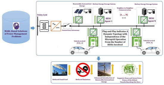
The attainment of successful solutions for power-storage flow management is at the forefront of the key drivers enhancing power-flow management performance in microgrids and V2G. This is due to the critical role played by energy-storage systems in maintaining renewable energy integration and localized balancing/regulatory services in decentralized and autonomous power-distribution networks [1,7,8]. Accordingly, there has been a sustained effort to attain active and efficient solutions; a taxonomy and summary of state-of-the-art approaches is given in [9], later expanded into [10], focusing on intelligent control solutions, given the success of approaches in this area. As discussed in these recent summary/review works, the introduction of multiagent reinforcement learning (MARL) has generally outperformed other AI applications for power-flow management in microgrids with multiple storage systems to manage. This is due to the direct learning from local observed data in the agents (with a minimal exchange of data to neighbors), allowing the relaxation of accurate model requirements, online adaptation with the qualification of applying offline measurements into the online applications, precise data-driven predictions with no forecasting model, and learning modes to optimize local and holistic power flows and balances [11,12,13]. Hence, there has been a significant focus on exploring and attaining successful solutions based on MARL, including primary–secondary regulatory and balance control as an intelligent emerging solution for solving complicated power-storage flow-management problems. The specific focus of this paper is to attain an improved MARL-based control for the battery-energy-storage systems (BESSs) of microgrid/V2G applications.
1.2. Statement of Problem
Despite the effectiveness and reliability achieved by the above-elucidated control approach in managing energy-storage systems, particularly batteries in the context of this article, the inaccuracy of the charge–discharge synchronization scenarios for the batteries has been an existing defect, especially under sudden high load variation or excessive continuous load fluctuation. A trade-off was identified between the consumption of the real-time energy-storage capacity and the charge–discharge synchronization precision. Hence, the accuracy tends to reduce with the increase in the real-time utilization of the battery’s capacity, constraining the effective capacity of the storage systems to maintain balance. Without artificial capacity constraints, the circulating current and temporary overloading of some storage systems in a network are existing drawbacks that upset the optimization and steadiness of the control, reduce the balance and sustainability of the power flow, deteriorate the health and life of the batteries, and limit the introduction and buffering capability of renewable energy [14,15,16]. DC infrastructure influences are a crucial magnifier for raising the impact of these drawbacks in real operation, potentially leading to the disparity of load participation due to the impact of the influence of the power electronics and transmission lines. This violates the charge–discharge synchronization accuracy if not adequately dealt with when designing the control system, and leads to the hypothesis that the compensation of these influences may lead to an effective capacity increase in the storage systems and improved performance under the MARL-based control.
Therefore, the infrastructure, primarily the transmission lines and power electronics, has a potentially major impact on the management of power-storage flow in the real-world operation of the MARL-based control for the following influences [16,17,18].
- Infrastructure influences are the major source of power losses in any electrical power system, whether it is generation, transmission, or distribution, and heterogeneous infrastructure around storage systems can have complex destabilizing effects if not compensated for.
- Infrastructure is a major influencer on the optimization and steadiness of the control process. Therefore, the proper compensation of DC infrastructure influences is a key factor in a successful control approach, and will be required for the balanced management of energy flow and long-term sustainability.
1.3. State-of-the-Art Summary
Per the above discussions, taking the DC infrastructure impact into account when designing the control system holds vital significance in raising the effectiveness of the balance control of storage systems in real operational environments. In accordance, there have been recent attempts to accomplish optimal or near-optimal solutions. In this sense, near-optimal implies close to the best possible, with convergence to optimal in an asymptotic limit for learning-based or adaptive solutions. J. Ma et al. [19] have suggested a sharing of the power flow and voltage control based on hierarchical control to minimize the transmission lines’ influence on the DC microgrids. However, the strategy still needs local infrastructure information in addition to the inconsideration of the energy-storage units, since they are different from other energy units due to the charge and discharge. The distributed hierarchical minimization of power losses was the suggestion by Y. Jiang et al. [20] to minimize the power losses of distributed energy resources connected in parallel to DC microgrids, wherein the hierarchical control was formulated to have a distributed gradient algorithm at the top layer, a consensus correction at the secondary layer, and then a droop correction at the local layer. Accordingly, an optimal current allocation was achieved based on the multiagent data exchange, even though local information was still required for infrastructure details, and there was no consideration of energy storage. A. Aluko et al. [21] proposed an adapted secondary control through the adaptation of the droop coefficient to include the transmission line resistance in a DC islanded microgrid. In accordance, the transmission line resistance impact appeared as an increase in the load demand that was subtracted from the secondary reference in the droop control to keep the output voltage balanced. Although, information is yet needed regarding the local transmission-line-resistive reactance, with no application on energy storage. This was followed by a suggestion based on droop gain adaptation by M.A. Mohammed et al. [22] to reduce the losses of power in a DC microgrid for an electric aircraft. A converter losses model was accomplished by adapting the droop gain to be equivalent to the converter series resistance. Hence, a minimization of the overall losses was achieved. However, some local infrastructure information is still mandatory. The most recent proposition by C. Guo [23] has followed the adaptation of the droop coefficient to compensate for the deviation of the output voltage due to the DC infrastructure influence in a DC microgrid. However, local information is still obligatory regarding the transmission lines’ DC resistance.
Therefore, based on the observation followed by the existing state-of-the-art:
- A commitment is compulsory to all or part of the local infrastructure information.
- Any modification in the local infrastructure requires a mandatory adjustment of the control strategy parameters and factors.
- Any reality variation in the local infrastructure influence, such as temperature variations, unmonitored infrastructure flaws, and an update of the infrastructure length or conductance material, results in the unbalance of the control process and a defectiveness of the microgrid operation.
1.4. Contributions
This paper proposes an optimized adaptive multiagent-based primary–secondary control to enhance the precision of the synchronization for the charge–discharge scenarios of distributed BESSs in a DC autonomous microgrid under realistic infrastructure influences, including a variable number of heterogeneous batteries, 24 h excessive variations in the load, environmental influences (temperature fluctuations), and infrastructure impacts. Specifically, an adaptation was suggested based on the multiagent neighbor-to-neighbor transfer of information to balance the immediate real-time participation level in the load consumption based on the neighbors’ real-time correction of the participation level. Furthermore, a method based on the neighbor-to-neighbor multiagent was introduced for the compensation of the DC infrastructure impact on the control, with no requirement for pregiven information on the local infrastructure. A compensator of the real operational influences was introduced based on the real-time local and neighbors’ measurements. Consequently, the voltage drop due to the DC real operational influences on the control was measured in real-time and then compensated at the decentralized secondary correction through an extra charge or discharge. Thus, qualitative improvements have been accomplished by the new optimized adaptive controller over the existing state-of-the-art to support the trustworthiness and success of the microgrid in real-world operations and to fulfill the below-demonstrated roles:
- Accurate charge–discharge synchronization and the enhanced steadiness of the output voltage of the BESSs under 24 h variations in the load, different operational conditions regarding different batteries’ capacities and dissimilar initial states-of-charge (SOCs), infrastructure influences, and the decentralization of the control and communication.
- A qualified compensation to the DC influence of the infrastructure on the control process during charge/discharge scenarios, with no need for preknown information regarding the local infrastructure specifications, such as the transmission line lengths and conductance material, under a decentralized communication and control.
- Enhanced overcoming of circulating current/overloading for the participating BESSs under the above-presented influences of the real operation.
- A developed protective plug-and-play with no violation in the steadying of the control process, the steadying of the output voltage, and the precision of the charge–discharge synchronization. Hence, the independence of the microgrid operation from the number of participating BESSs.
1.5. Article Structure
The rest of the paper is structured as follows. Section 2 provides a full detailed explanation of the design and operational methodology of the proposed extended MARL-based control strategy for plug-and-play with infrastructure compensation. A presentation of the achieved results, with a comprehensive discussion, is given in Section 3. Finally, an informative conclusion is provided in Section 4.
2. Methodology
2.1. Approach and Theory of Control
2.1.1. Theory
The principle and development strategy for the proposed adapted multiagent primary–secondary control is based on the exploitation of the fundamental features of the MARL power-management approach toward the accomplishment of the above-explained optimized adapted solution (in the Section 1.4) for the control issue investigated (in the Section 1.2) of the MARL-based primary–secondary control. The MARL approach is an active, successful, and emerging solution to potentially solve complicated power- and energy-management problems in multistage/multidimensional power, generation, storage, and distribution environments, such as microgrids. Hence, it fundamentally serves the fulfillment of multidecisionmakers in a unified environment. Each independent decisionmaker in the MARL approach is an agent responsible for taking action () in the power-management environment based on an individual received state () and perceived reward (), as demonstrated in Figure 1 [24,25].
Multiagent primary–secondary management was a prominent recent MARL application for solving power-flow management in modern decentralized networks, especially managing power-storage flow. Thus, many recent power-management research works have suggested the active and successful applications of managing energy-storage systems based on MARL, where the management of battery-energy-storage systems was the most successful [10,26,27]. The success of the abovementioned MARL-based control is promoted by three fundamental features. The first is that there is no necessity for a central control authority or communication (although it may be prudent to have some minor central regulatory agent for critical service regulation, acting as the system operator, which can be achieved with MARL). This model is envisioned for the decentralization of control and communication in a utility-free power-distribution network to implement a variety of distributed demands, such as in rural areas, industrial clusters, the grids of microgrids, and distributed V2G charging units, wherein the management policy of each independent agent of the MARL-based primary–secondary control is entirely dependent on local measurement and neighbor-to-neighbor communication, as explained in Figure 2. The last one refers to the general construction of the MARL-based primary–secondary control policy [10,28,29].
The second feature of the MARL-based control is the more precise stability and balance that can be accomplished (in principle) in the control process due to the several cascade-correction stages, as shown in the general structure of the conventional multiagent-based primary–secondary management in Figure 2. Specifically, the management of each battery-energy-storage system (BESS) in the approach is through a decentralized, multistage, and multicorrection approach. Each stage of the decentralized-agent-based controller corrects for the stage before it in a cascaded, supervisory trimming situation. The first stage of the primary is local regulation, which is responsible for managing the power-storage flow of the BESS. This is further corrected by the second stage of the primary, which is based on the level of participation in the overall load demand. The first stage of the secondary corrects for the primary management. This is under the further correction of the second secondary stage based on multiagent neighbor-to-neighbor communication (normally a consensus correction based on a multiagent neighbor-to-neighbor correction from the neighbors) [10,29]. The third valued feature of the MARL-based policy is the possibility of boosting the accuracy and raising the intelligence through the introduction of adaptive or nonlinear elements coupled with machine learning (ML), for example, through an artificial neural network (ANN), as outlined in Figure 3. The last one demonstrates the general structure of the ANN-based reinforcement learning. In particular, the accomplished actions are compared with other possible successful actions to track toward the optimized solution. Accordingly, the application of the ANN-based MARL control on complicated multivariable nonlinear control applications requiring high accuracy has shown significant success, such as in autonomous vehicles, aircraft applications, nuclear management, and high-rate renewable/intermittent power control units [27,30,31,32]. The MARL-based control has earned remarkable success in solving complicated power-storage control defects, specifically in balancing the flow of power storage in advanced applications of power distribution, such as micro/smart grids and V2G [17].
2.1.2. Communication in MARL
The application of a multiple-agent approach that interacts and influences in a shared environment has been successfully introduced in modern power management. Accordingly, mandatory decentralization and autonomy are fulfilled for making decisions regarding power-flow organizing, especially power-storage flow [10]. This is due to the capability of the group of agents that are distributed in a common environment to communicate their information, such as sharing their local observations, current and future intentions, and their experiences from previous observations, to enhance the stability of the learning. Accordingly, a better knowledge of the environment can be achieved by each agent to accomplish the better coordination of the behavior [33]. Therefore, the agents’ communication in MARL (Comm-MARL) plays a significant role in improving the agents’ learning in the RL (improving the learning through communication). The systematic and structural way of establishing a Comm-MARL can conventionally be categorized into nine main dimensions, as demonstrated in Figure 4, further identified in the below points [33,34].
- Type of communication: This dimension identifies the communication topology for which agents intend to communicate with each other or send/receive immediate messages. In a multiagent system interacting in an environment, agents directly communicate with each other under different categories based on the communication topology. “Neighbor-to-Neighbor” learning allows communication only with the neighbors’ agents. This has several successful applications for fulfilling the intelligent decentralization of managing the power flow, particularly power storage, such as the multiagent primary–secondary strategy of managing the BESSs. While the communication is not limited to the neighbors’ agents in the “Other Agents Learning”, in the “proxy-based Comm-MARL”, communication is indirect between the agents, where a medium agent is provided to be viewed first by the agent.
- Type of policy: The policy in the Comm-MARL refers to the intentions and motives of making decisions to make communication and transfer messages (building a communication link). This can be either mandatory/predefined under specific requirements or learned based on the requirements of providing the best communication to enhance the learning of the environment.
- Communication messages: This signifies the piece of learning information that is decided to be transferred through the communication link. This might include a mandatory update of information and historical experiences/future intentions to enhance the learning. Furthermore, it can be sent directly between the agents or in multiple steps via the proxy agent.
- Combining messages: The immediately received multiple messages need to be combined before processing to the agent’s internal model. An independent decision by the agent is taken on how to combine the multiple messages if the proxy is missed. Otherwise, the combining role is the proxy’s responsibility.
- Integration: The integration of the combined messages to the agent’s learning is classified based on the part of the model involved in the “Policy-Level”, when the combined messages are imported to the policy model (which means the received messages are considered in the next intending action), the “Value-Level”, when the messages are received at the value function (the Q-table), and the “Policy-Value-Level”, when both levels are responsible for integrating the combined messages.
- Constraints: Real-world influences might establish limitations on communication in MARL, such as the cost of communication and noisy environments. Accordingly, a variety of constraints in communication were found, such as the limitation in the bandwidth, a change in the messages’ distribution due to noisy environments, and transmitted messages’ combinations through one medium.
- Learning: Learning in the Comm-MARL denotes the update, followed by communication protocols, communication policies, and the messages’ contents, based on the level of learning for the agent. Utilized feedback (or reward) exists in MARL, allowing for the backpropagation of the gradients between the agents to enrich the agents’ communication learning. In accordance, learning in communication can be classified based on the way to utilize the feedback, where the learning is “Reinforced” if another RL algorithm is employed, and “Differentiable” if the learning in communication is improved by the backpropagated gradients from the previous communicatees, with no further added RL algorithm.
- Training: The scheme of training in the Comm-MARL explains the dimensional determinations of utilizing the received experience. This can be classified as “Centralized-Learning” if the experiences are grouped in a central unit for the learning of all agents, and “Decentralized-Learning” if the experience is received individually by each agent through independent training.
- Goal: The aim of controlling the agents can be classed as “Cooperative” when the performance of the whole team is the point of focus, “Competitive” if the aim is only maximizing the local reward, and "Cooperative–Competitive" if a mixed aim of the previously explained aims is the requirement of the control.
The Markov game (MG) is the multiagent version of the Markov decision process (MDP). Accordingly, the learning of the N number of agents interacting in a unified environment can be represented by a set of states (S) based on a set of observations, Qi (i ϵ N), and actions, Ai (i ϵ N). Therefore, in any immediate timing step of the agent i, the action is taken, ai ϵ Ai, the reward is obtained as a function of S, ri: S × Ai → R, and the observation is taken, Oi: S → ON. Hence, any distributed agent aims to maximize the discounted reward (Ri), as explained in (1). Here, γ ϵ [0, 1] is the discounting factor [5,35].
The communication protocols and conversation policies are the framework of the agents’ communication within the unified environment, where a hidden state of the encoded observation is attained; then, a decision is made regarding who the intended recipient agent of the message is and when each agent should send a message through the scheduling, as explained in the scheduling function (fshed) in (2), in which the encoded messages are arranged based on the scheduling policy in the graph of the output messages . Nm is the number of encoded messages and Lg is the number of scheduled graphs. Then, a decision is made based on the integration of the received messages through the processing, where the target encoded message in the specific scheduled graph is processed based on the followed policy for the received and through the processing function (fmp), as formed in (3). Finally, the experiment is shared with the other agents responsible for the communication to enhance the training, as explained in Figure 5 [35].
Hence, the agents communicate based on the followed protocol and the communication type. Figure 6 demonstrates the neighbor-to-neighbor communication that was verified between the interacting agents through direct communication links via immediate messages and the combinations of messages based on the communicative act with no proxy. For the practical implementation, TCP/IP or UDP/IP datagrams (either with or without priority, time-synchronized clocks, and bandwidth reservation) can be used within a wider Internet-of-Things (IoT) framework. Transmission latency and delays will be very low (typically on the order of µs) in most practical situations when compared to the frequency of the message queuing/update (typically on the order of ms). This will be especially true when a dedicated ‘utility intranet’ or microgrid communication platform is deployed.
2.2. Principle of the Operation
This study reflects the application of the proposed adapted multiagent primary–secondary strategy with the compensation of the DC infrastructure influence on each BESS of the DC autonomous microgrid; the infrastructure impact is demonstrated in Figure 7. The aim is to implement a 24 h variable-load demand, balanced collaboratively by the participating (i = 1 → N) number of battery-energy-storage systems (BESSs) and using a 24 h solar-generation profile to offset the grid load. Furthermore, the presence of the multiagent bidirectional neighbor-to-neighbor transfer of information is assumed (note that no specific communication channel characteristics are assumed, and that no encoding/quantization errors, packet overheads, packet losses, or packet latencies/jitters are assumed to occur). Accordingly, a bidirectional transfer is fulfilled between the neighbors’ BESSs of the immediate real-time measurements for the voltage consensus correction (VLi_dash), the current consensus correction (ILi_dash), the locally measured state-of-charge (SOC_i), and the correction for the participation level based on the required load consumption (Vref_droop_i_M). The variable measured DC-resistive influence of the local infrastructure for the branches of the microgrid’s distributed regions are as follows: the load-line-resistive influence (RSi), the BESS-line-resistive influence (RBi), and the transmission-connection-line-resistive influence (RTi), respectively. The distributed BESSs are formulated as agents operating within the microgrid environment, each fulfilling an independent local power-flow balance; in addition, collaborating with the neighbors’ BESSs to accomplish the overall balanced sustainable power flow of the microgrid. Therefore, a corrected level of participation is attained at each BESS under the active compensation of the DC infrastructure influence on the control, with no necessity for preprovided information on the local infrastructure details. Hence, the precise synchronization of the charge–discharge scenarios is implemented for the microgrid power-storage flow by the below-elucidated suggested decentralized multistage infrastructure-influence-compensator control strategy.
2.2.1. The Compensation of the DC Infrastructure Influence on the Control
The compensation of the DC infrastructure influence on the control process holds vital significance in the power-flow balance of the microgrid’s real-world operation. Thus, the success, validation, and optimization of the control in the real-world operation depends entirely on how successful the compensation of the DC infrastructure influence is [36,37]. Accordingly, a compensation method based on multiagent neighbor-to-neighbor communication has been introduced to locally compensate for the infrastructure impact on the control process, with no need for pregiven information regarding the local infrastructure details.
The proposed real-time decentralized multiagent-based infrastructure-influence compensation of the Nth region (BESS N) and the region before it (BESS N − 1), explained in Figure 8, is based on the idea of converting the DC infrastructure impact into the form of an immediate real-time measured voltage drop at the distributed infrastructure branch. This voltage drop can be subsequently compensated by the decentralized secondary correction of each distributed BESS. This relatively straightforward approach reduces the violation of the charge–discharge synchronization accuracy and the deviation of the output voltage, assuming that an appropriate equivalent voltage drop can be synthesized. Since the operational methodology of each decentralized BESS in the microgrid experiences different instantaneous operational conditions and scenarios, three scenarios were constructed to emulate the real operation in the simulations and hardware-in-the-loop (HiL)-based experiments. These scenarios were taken into consideration when measuring and compensating for the DC infrastructure impact on the controller regarding the discharging participation, charging participation, and plug-and-play off-participation, as described below [16,36,37].
Infrastructure-Influence Compensation during Charging
The successful compensation of the DC infrastructure influence on the control during charging is important for reasons discussed in the Introduction and further summarized here. This is due to the high current flowing through the microgrid network, since the PV generation implements the load consumption in addition to charging the participating BESSs with a negative battery current (Ib_N < 0). Accordingly, the charging scenario of the (N) number of BESSs in the microgrid reflects an inversely proportional relationship between the voltage at each distributed node and how far the node is from the voltage of the main source, represented by the microgrid bus voltage at the photovoltaic (PV)-generation side (V_bus). Hence, the voltage difference between the voltage at the distributed node (VCN) and the voltage at the neighbor-region node before it (VCN − 1), which is already measured locally by the neighbor BESS N − 1 and sent to the BESS N via the multiagent neighbor-to-neighbor communication, is due to the DC infrastructure impact of the Nth region transmission connection branch (RTN). This introduces a disparity of the DC bus voltage at each distributed region. Thus, this raises the DC current at the transmission connection branch (ILTN) flowing between the microgrid-distributed regions, as clarified in Figure 5. In consequence, the below-explained impacts are experienced:
- The voltage equilibrium of the microgrid DC bus is violated.
- The charge–discharge synchronization accuracy is disrupted.
- The balance of the BESSs’ participation level in load demand is compromised.
- The control process stabilization is negatively affected.
Therefore, based on the above-demonstrated remarks, the vital DC influence of the infrastructure on the control strategy comprises any influence within the boundary of the control environment, and is typically not included when designing for the control stability factors. Since the decentralized control methodology aims to balance the output voltage at the load terminals, the increase in the load voltage due to the DC load branch infrastructure impact in the form of a voltage (VRSN) introduces a disparity in the load-participation balance. Likewise, the voltage due to the DC infrastructure impact at the transmission connection branch (VRTN) establishes a real-time interruption in the balancing sustainability for the microgrid bus. Whereas the voltage due to the BESS line infrastructure impact (VRBN) affects the increase in the infrastructure losses, it does not affect the control process, because it is not included when designing for the control factors.
Subsequently, to compensate for the infrastructure influence on the controller, it is obligatory to consider the VRSN and VRTN when designing the control system. The conventional method of compensating for the DC infrastructure influence of the control is to add the DC impact of the infrastructure to the calculation based on the given infrastructure technical details and then multiply it by the real-time measured currents flowing in the branches to attain the immediate real-time measurement, including the infrastructure impact. Hence, the accomplished real-time impact is added to the stability factors of the control, thus formulating the control rules to provide sufficient compensation for the impact.
Consequently, the design based on the existing method is active and convenient when the accuracy is followed for identifying the infrastructure influence based on the administrator’s technical information. Thus, the control formulas are adapted to provide sufficient compensation. However, a defectiveness of the reality operation is present due to real-world operational influences, such as a lack or unavailability of all or some infrastructure details, a regional change in the infrastructure, environmental influences, unmonitored infrastructure flaws, and updates to the infrastructure length, conductance material, switches, breakers, power electronics, etc. Therefore, based on the existing method, any update of the infrastructure due to the above-stated real operational influences requires the adjustment and update of the control. As a summary of the above-presented, it is mandatory when designing a control system to consider all the expected events during the real operation of the system and the long life of its operation.
A solution based on the multiagent neighbor-to-neighbor has been suggested to overcome the previously explained issue. Thus, the immediate real-time compensation of the DC infrastructure influence on the control was fulfilled with no need for preknown information regarding the infrastructure details, wherein the advantage was taken from the local and neighbor immediate real-time measurements of the voltages and currents through multiagent communication. Specifically, an assumption was adopted for the VCN and VCN − 1 to be equal. Thus, the immediate real-time measurement of the voltage difference (VRSTN) between the VCN and the real-time measured load voltage at the Nth branch (VLN) refers to the VRSN plus the infrastructure impact voltage drop at the transmission connection branch (VRTN), as demonstrated in (4)–(6) and Figure 4 and Figure 5. Next, an adapted reality-influencing real-time output voltage (VLRSN) was accomplished by adding the VRSTN to the VLN before the application to the decentralized primary and secondary control, to be compensated by a demanded charge or discharge, as shown in (7) and Figure 5.
Hence, the compensation of the infrastructure influence on the control of the suggested method is based on converting the rise of the participation current at the specific branches, which is higher than the actual demand, into a locally measured real-time voltage drop. Since the influence on the control due to most real operational infrastructural and environmental impacts in a DC network is reflected in a variation in the current flowing at the branches, it is immediately compensated in real-time after applying it to the controller by a demanded charge or discharge. Therefore, the proposed method is qualified for the maintained balance, stability, and reliability of the control process and the enhanced precision of the charge–discharge synchronization of the participating BESSs under the previously stated real-world operational influences, with no requirement for the information regarding the infrastructure details.
Infrastructure–Influence Compensation during Discharging
The influence of the infrastructure on the control during discharging requires less compensation. Discharging is verified when the PV generation is unavailable and the battery current is positive (Ib_N > 0). Hence, the current flowing from the microgrid network is purely the collaboration of the load-demand implementation by the participating discharging BESSs, as clarified in Figure 8. Therefore, the immediate real-time measured BESS voltage (V_Bat_N) was higher than the voltage at both regionally distributed nodes, the VCN, and the VCN − 1, since the participating BESSs occupied the role of the main source during the discharging scenario. Thus, depending on the method assumption in (1), the immediate real-time measurement of the DC infrastructure-influence-compensation voltage drop can be determined in (2) and (3). Furthermore, the adapted reality-influencing real-time output voltage can be measured in (4).
Infrastructure–Influence Compensation during Plug-and-Play
Plug-and-play in the microgrid signifies the scenario when the BESS ends the participation in the implementation of the load demand and then restarts the participation after an unknown time, and vice versa, based on a participation policy by the administrator or the BESS owner. A typical example of such an operation is in V2G applications, in which batteries from electric vehicles (EVs) can dynamically enter and exit an aggregated, distributed storage schema for the provision of wider grid-balancing services. Here, the BESS N is assumed to be out of the participation, with zero battery current (Ib_N = 0). Hence, there is no existing infrastructure impact at the BESS N branch, although the real-time measurement is still active in measuring the DC infrastructure influence of the branch for both charging and discharging scenarios if the multiagent communication is in activation. Thus, all the measurements of the infrastructure influence can be fulfilled in real-time, imitating the above-presented participation scenarios in charging and discharging.
Accordingly, an active decentralized multiagent-based compensation of the infrastructure and the operational influence on the control process has been accomplished in immediate real-time at each BESS to enhance the quality, reliability, and optimization of the proposed adaptive decentralized primary–secondary control approach. Thus, fulfilling the below-demonstrated talents:
- Immediate real-time compensation of the DC infrastructural and operational influences on the control process, with no need for preknown information regarding the infrastructure details. A detailed explanation is presented in the below demonstration of the proposed control stages. Hence, the optimization, reliability, and robustness of the control are accomplished to verify the mandatory power-storage management of the microgrid in real operation.
- Given the DC impact of most of the environmental and infrastructural influence, and many of the accidental and operational faults in DC networks are violations of the current balance, the proposed adapted control strategy, with the suggested compensation of the infrastructure influence, supports an active, robust, reliable, and sustainable balanced power-storage flow in uncertain and inconstant environments with a large probability of load variations.
2.2.2. The Decentralized Control—Primary Level
A decentralized primary power management based on droop correction has been designed to implement the mandatory power-storage flow policy of the microgrid. Accordingly, any deviation of the output voltage due to a requested correction of the load participation by the secondary correction is translated into a charge or discharge. Thus, the balance of the real-time locally measured output voltage (VLi) is maintained to the microgrid nominal voltage (Vmg) of the DC level, as presented in Table 1.
Particularly, a two-stage control approach was locally formulated to fulfill the compulsory modification of the load participation by droop correction through a requested battery charge or discharge. Stage 1 is responsible for a real-time reference of the battery current (IB_ref_Ch_Dis_i) to compensate for the voltage error (ev_pri) of the locally measured real-time reality-influencing output voltage, including the DC infrastructure influence (VLRSi), from the adapted real-time droop correction voltage reference (Vd_i), as demonstrated in (8) and (9), and Figure 9 and Figure 10. Figure 9 presents the primary power regulation under the existence of the DC infrastructure impact, whereas Figure 10 explains the proposed adaptive decentralized primary–secondary control approach. VLRSi signifies VLi plus the voltage drop due to the infrastructure impact (VRSTi), as clarified in (10). Hence, the deviation impact of the infrastructure is immediately compensated in real-time to prevent the disruption of the load-sharing balance and the violation of the precision of the charge–discharge synchronization. The percentage limits of the VRSTi vary depending on several operational/infrastructural influences, such as the length and properties of the conducting material of the transmission lines, the infrastructure/equipment efficiency and reliability, the age and wear of the infrastructure components, the level of the batteries’ heterogeneity, the load-demand limits and the variation ratio, and temperature disparities [30]. In accordance, the percentage limits of the VRSTi of the DC microgrid under the proposed adaptive primary–secondary strategy and the nominated level of infrastructure was 0.034–3.8208% of the Vmg. Next, a control action of the current (ei_c) was accomplished in the second stage to be applied to the power-width modulation (PWM) and to create the control of the converters’ switches. The parameters and the switching frequency of the converters are shown in Table 1. The accomplished control action is based on the current error (ei_pri) of IB_ref_Ch_Dis_i from the real-time locally measured battery current (Ib_i). This denotes the requested battery charge or discharge to verify the mandatory power-flow balance, as shown in (11) and (12), and Figure 9 and Figure 10. and are the primary voltage proportional/integral gains, whereas and are the primary current proportional/integral gains, respectively, with their values demonstrated in Table 1 [15,37,38].
Implicitly, the primary local regulation of the power-storage flow is under the droop correction regulatory control with a supervisory trim signal. A droop regulator was designed to correct the local power management, and a droop correction reference (Vref_droop_i) was formed in (13) based on subtracting the locally measured contribution of the load consumption (ILi) in the form of a voltage drop at the nominated droop coefficient (rdi) of the value, as shown in Table 1, from the real-time secondary correction reference signal (Vref_sec_i). Thus, an adaptive collaborative real-time reference of the local regulation (Vd_i) was determined based on the average neighbors’ BESSs real-time droop drop due to the variation in the load demand by the multiagent communication (Vref_droop_j_M), including the local (Vref_droop_i_M), as shown in (14) and Figure 4 and Figure 8. Ni implies the number of neighbors’ BESSs. Thus, any variation in the distributed load demand was implemented collaboratively by the existing in-participation BESSs. Therefore, an enhanced reduction in the circulating current/overloading was fulfilled. This is reflected in the maintained accuracy of the charge–discharge synchronization, the optimized steadying of the control process, the better battery health, and the longer usage life [10,15,37].
2.2.3. The Decentralized Secondary Correction
The combinational correction role of the real-time decentralized secondary correction, under the control methodology of the proposed adapted strategy, comprises the correcting output voltage (Uvi), the participation level in the load demand (UIi), and the SOC synchronization (USOC) through an introduced qualified real-time correction platform. Hence, the real-time balance of the voltage at this point was maintained at Vmg, as presented in (15). In accordance, a real-time secondary control reference was achieved (Vref_sec_i) to request an extra charge or discharge upon the compensation of the requested correction to fulfill the mandatory balanced power-flow policy [15,37].
The Decentralized Voltage Correction—Secondary Level
A decentralized secondary voltage correction was fulfilled through the accomplishment of a voltage-control action (Uvi) by a qualified designed controller. Accordingly, the secondary voltage error (ev_sec) was compensated to keep the real-time voltage consensus correction (VLi_dash) balanced to Vmg, as shown in (16) and (17), and Figure 8. and are the proportional/integral gains of the secondary voltage control, respectively, with their values presented in Table 1. Hence, the imbalance of the output voltage was overcome by a charge or discharge at the secondary control [10,15,37].
The Decentralized Secondary Correction of the Participation Current
A real-time secondary correction of the participation level in the load demand has been verified through a designed correction controller. In consequence, the secondary current error (ei_sec) related to the deviation of ILi from the secondary current consensus correction (ILi_dash) was compensated by an accomplished control action (UIi), as demonstrated in Equations (18) and (19), and Figure 8. The last one explains the proposed decentralized adapted strategy. Thus, any mandatory correction of the participation current was executed at the secondary correction by a requested charging or discharging. and are the current-correction proportional/integral gains of the values, respectively, which are available in Table 1 [10,15,37].
The Secondary Correction of the SOC Synchronization
An SOC correction approach has been applied to improve the precision of the charge–discharge synchronization for the participating BESSs under the real operational influences, such as an excessive continuous load variation, a variated number of BESSs in the microgrid, unequal battery capacities and dissimilar initial SOCs, environmental impacts, and infrastructure influences. Thus, the SOC synchronization error (eSOC) due to the deviation of the locally measured (SOC_i) from the average neighbors’ SOC (SOC_dash) is compensated by a created control action (USOC), as explained in (20)–(22) and Figure 10. Hence, a charge/discharge is requested by the secondary correction to eliminate any violation of the SOC synchronization accuracy. and are the SOC regulation proportional/integral gains and the number of BESS neighbors, respectively, with their values shown in Table 1 [10,15].
Since the precision of the charge–discharge scenario synchronization is maintained by the above-clarified correction approach, this offers a significant reduction in the circulating current and overloading for the participating BESSs. Hence, a better stabilization of the control system, the enhanced health and life of the batteries, a reduction in the losses, and an improvement of the system performance and reliability of the real operations can be accomplished with the noteworthy support of a renewable energy introduction and sustainability.
2.2.4. The Decentralized Secondary Correction Based on Consensus
A consensus-correction protocol has been introduced to fulfill a collaborative distributive balance of the output voltage and the level of participation in the load consumption for the distributed BESS with the neighbors’ BESSs based on multiagent bidirectional neighbor-to-neighbor communication. Consequently, the deviation of the local voltage due to a requested correction of the participation level in the load demand is compensated collaboratively by the BESS and the neighbors’ BESSs. Hence, the overall mandatory balance of the microgrid power management is verified [5,31]. Particularly, a real-time voltage consensus correction has been formulated. Thus, an evaluation was conducted between the local’s (VLi_dash) and neighbors’ (VLj_dash) voltage consensus correction, then corrected based on the Vmg, multiplied by the voltage consensus gain (av) of the value demonstrated in Table 1, and divided by the neighbors’ number (Ni) before sending it to the neighbors to be corrected collaboratively. Next, the accomplished consensus correction was added to the reality-influencing real-time measured voltage (VLRSi) to retain the balance with Vmg under the DC influence of the infrastructure, as shown in (23) and (24), and Figure 11, as well as the proposed adapted primary–secondary control strategy in Figure 10. The VLRSI signifies VLi, plus the voltage drop due to the infrastructure influence (VRSTi). Accordingly, the voltage deviation due to the DC infrastructure influence was applied to the secondary correction. Thus, it was rapidly compensated through a requested charge or discharge. Therefore, an enhanced balance, stability, and reliability of the control process was attained under the influence of the real operations. This implies an improved precision of the charge–discharge synchronization, a reduced circulating current/overloading of the contributing BESSs, and supported battery health and an extended usage life [10,15,37,39].
Complementarily, a current consensus protocol was designed to verify a consensus correction of the participation level in the load demand based on the multiagent neighbor-to-neighbor transfer of information. In accordance, a correction to the level of the participation in the load demand was attained based on the evaluation between the local’s (ILi_dash) and neighbors’ (ILj_das) current consensus correction. Then, it was multiplied by the current consensus gain (ai) by the value shown in Table 1, and divided by the number of neighbors’ BESSs (Ni), before being directed to the neighbors to be corrected by all the neighbors. Finally, the correction was added to the ILi to implement the mandatory correction of the participation level, as presented in (25) and Figure 10 [10,15,37,39].
2.2.5. Plug-and-Play Insertions and the Removals of the BESSs
The aim of plug-and-play, based on the suggested adaptive multiagent primary–secondary control, is to guarantee the balanced management of the individual start/end points of the participation in the load demand for the N number of decentralized BESSs in the microgrid. Thus, the independence of the microgrid power flow from the number of contributing BESSs is verified [15,34]. Accordingly, a qualified trustworthy protective plug-and-play was proven based on the MARL neighbor-to-neighbor transfer of information. Each distributed BESS was formulated as an independent agent sharing with the neighbors the mandatory power-flow information. Hence, it fulfills a regional balance of the power-storage flow based on the load-consumption requirements by the administrator. Consequently, the plug-and-play technical feature has seen widespread application in modern multidemand power-distribution approaches, particularly in V2G charging, wherein the number of participating V2G units is partially dependent upon the demand level, and also the number of available units at any one particular time; this is based on the expectation of any individual V2G BESS unit to start or end the participation depending on the demand availability and local restrictions, such as the driver constraints on the availability for V2G participation. Since the number of power-storage units becomes a variable factor (in the worst case, purely stochastic in nature), it raises the uncertainty and nonlinearity of the resources available in the power-management environment. Thus, the independence of the BESS management effectiveness from the number of participating BESSs in the microgrid (in a control-theoretic sense) supports the reduction of the uncertainty and nonlinearity of the network environment [40]. Note that a reduction in the number of available units may increase the external power drawn from the microgrid due to the lowered aggregate capacity of the storage: the importance here is that the control stability, the maximization of both the available/useable capacity of the participatory BESS units, and the energy efficiency of the schema are the factors of concern.
The consideration of the real operational influences, mainly the infrastructure, when formulating the plug-and-play holds vital importance. The balance during the plug-and-play depends entirely on the level of accuracy in the charge–discharge synchronization. Even though the infrastructure influence is the main motive for violating the accuracy of the charge–discharge scenarios, and the DC infrastructure influence is compensated by the qualified proposed strategy, there is still the need for protection against any out-of-control rise of currents and voltages due to the impact of the infrastructure influence, whether the conventional DC influence of the conductors or declared/undeclared faults. Hence, collaborative participation management is implemented, as explained in the multiagent topology and plug-and-play policy of the BESSs’ agents in Figure 12, at each BESS to verify the protective management of the level of participation based on the battery-rated currents and voltages.
A demonstration example is the BESS N in the DC autonomous microgrid, which ends its participation in the load demand if the measured real-time battery current (Ib_N) is higher than the battery-rating current (Ib_Max) for both the charging and discharging, or if the measured battery voltage (VB_N) is higher than the maximum, full-charge battery voltage (VB_Max). Thus, the nearer BESS occupies the neighbor role instead, with no influence on the steadiness of the control process and the precision of the charge–discharge synchronization. Therefore, a developed, qualified, reliable, and protective plug-and-play is verified under real operational influences to fulfill the below-demonstrated tasks [15,34].
- Participating BESSs can end the participation individually at any time, and for an unknown time period, with no effect on the steadiness of the control strategy and the precision of the charge–discharge synchronization for the participating BESSs.
- The enhanced protection of the power and control infrastructure against a faulty out-of-control increase in the batteries’ voltages and currents higher than the nominal ratings. Hence, this supports enhanced system protection and healthier long-life batteries.
- Since balanced plug-and-play can be verified on each BESS, independence is verified in the power-flow balance from the number of participating BESSs in the microgrid.
3. Results and Discussions
The proposed adapted decentralized multiagent-based strategy has been applied to each BESS of the 48V DC autonomous microgrid, as shown in Figure 1, to verify the success and discuss the performance. The system parameters (the microgrid nominal voltage, the ratings of the batteries involved, the parameters and the switching frequency of the designed DC–DC converter interfacing the battery to the DC bus of the microgrid, and the gains of the designed controllers/correction stages of the proposed strategy) of the conducted experiments are presented in Table 1. A 24 h extremely variable load was also implemented, served collaboratively by the participating BESSs and an additional 24 h solar-PV-generation profile. Furthermore, the presence of the multiagent neighbor-to-neighbor transfer of information, as described previously, was assumed. The charging temperature was initially assumed to be room temperature (25 °C). Furthermore, the method followed for charging the BESSs with renewable energy was considered as a constant voltage (CV) to allow the battery to charge to full by the charging current, then the charging current taper down to the minimum value and the BESS wait for its participation in the load demand. The charge–discharge of the BESSs was formulated to be within the threshold followed (20% minimum and 80% max), but the most that was followed, as indicated by the result for the SOC, was close to 50%. The state-of-health (SoH) was not considered at this level of the project, where the concentration was on the batteries’ control rather than the batteries’ behavior, but it will be given more attention in further steps to investigate more of the batteries’ heterogeneity and second life. Case studies were conducted in real-time considering the influences of the real-world operation of a variable number of BESSs, different batteries’ capacities/initial SOCs, and the DC infrastructure influences to carry out the verification of the proposed plug-and-play.
3.1. Case 1: The Suggested Adaptjve Strategy—Three BESS Agents in the Microgrid
The proposed adapted strategy with the compensation of the infrastructure influence has been implemented on N = 3 BESSs in the microgrid. As discussed, the expected real operation was considered, and different batteries’ capacities (9, 10, and 11 Ah), different batteries’ initial SOCs (48%, 50%, and 52%), and the variable-measured resistive-DC-infrastructure influence of the microgrid branches (as defined in the table) for the distributed regions in the microgrid were considered, as presented in Table 2. Hence, this covers most of the real-world operational scenarios; for example, the different classes/ages of the batteries, environmental influences, mainly the temperature, undetected faults, undeclared repairs, a permanent or temporary update of the infrastructure lengths or components, and the infrastructure suffering from partial wear, since the impact of all the pre-explained influences is an increase in the flowing current. The aim was to highlight the impact of the newly introduced adaptation on the optimization and reliability under the flawed expected real operational influences.
The accomplished results in Figure 13a demonstrate the precise synchronization of the charge–discharge scenarios and the steadiness of the output voltage under the 24 h load variation implementation, as shown in Figure 13c; furthermore, the availability of the PV generation based on the 24 h PV-irradiation profile, as presented in Figure 13d. However, a violation of the charge–discharge synchronization accuracy at the times 16.3 and 20.4, and a deviation of the output voltage, are observed due to the excessive continuous load variation and the DC infrastructural/operational influences.
The results in Figure 13b confirm both an improved precision of the charge–discharge synchronization and a rapid stability of the output voltage under the proposed optimized adapted primary–secondary control. In addition, the qualified compensation of the DC infrastructure impact is evidenced. This was due to the success of the proposed adapted strategy in verifying the following tasks:
- The successful multiagent-based balance of the participation level in the load-demand implementation.
- The enhanced precision of the charge–discharge synchronization for the participating BESSs in the microgrid under real operational influences.
- The good compensation of the DC infrastructural/operational influence on the control strategy. Thus, the balance of the control process was improved under the most expected real-world operations.
Accordingly, an enhanced stabilization of the output voltage was verified based on the accomplished results and under the application of the proposed adapted strategy with the compensation of the infrastructure influence. The line chart in Figure 14, which demonstrates the measurements of the output voltage in Table A1, confirmed the outperforming of the proposed strategy with the compensation of the DC infrastructure influence over the existing strategy in terms of the output voltage balance by an average enhancement of 1.385% if the measurements were considered during the 24 h operation. The average enhancement was raised to 2.2246% if the measurements were considered merely during the critical operation times. This proves the outclassing of the proposed strategy in terms of the load-implementation stability due to the rapid compensation by the proposed adapted strategy of the output-voltage deviations, which are a result of the below-explained influences:
- The defilement of currents’ balance due to the DC infrastructure/operational influences.
- The disparity of the load participation by the heterogeneous batteries (different batteries’ capacities/initial SOCs).
- The impact of excessive continuous load variation.
- The violation in the charge–discharge synchronization accuracy.
The impact of the control on the power consumption signifies a critical importance, wherein the success of a control approach is evaluated by the amount of savings and the balance acquired from the power flow during a specific time. Hence, it is mandatory for any proposed solution to a defect related to power flow, whether the system is for generation, transmission, or distribution, to be in the interest of improving the power production. In accordance, the real-time total power consumption during a 24 h operation of the microgrid based on the above-demonstrated results has been tracked. The aim was to investigate the impact of the proposed adapted strategy on the power consumption during the 24 h excessive continuous load variation. Thus, an average reduction in the total power of 1.995% was earned when the total power consumption was measured throughout the 24 h operation of the microgrid. The average reduction was raised to 2.367% when only the critical times of the microgrid operation were considered. This was based on a measurement of the total power consumption per one-hour consumption at several operational times during the 24-h operation of the microgrid, as demonstrated in Table A2 and the representative line and bar charts in Figure 15. Additionally, a saving of the power consumption of 1.83% was achieved based on the measurement of the total power consumption in 24 h, raised to 1.942% when the consumption measurements were taken during the last critical 14 operational hours of the day. This proves the success and outperformance of the proposed strategy with the compensation of the infrastructure influence over the existing strategy in terms of the power consumption, especially during the critical time of the microgrid’s real operations and under the most real operational influences. This is owed to the better stabilization and balance of the control process by the enhanced precision of the charge–discharge scenario synchronization of the participating BESSs in the microgrid and the improved rapid balance of the output voltage against the 24 h continuous variation in the load demand; moreover, to the successful elimination of the circulating current and the overloading defects under the previously mentioned real-world operational influences.
In line with the above, the balance of the power flow is no less important than the reduction in the energy consumption, wherein it is, likewise, an assessment of the success and validity of a control approach. Thus, it is vital and mandatory to evaluate the proposed adapted strategy based on the accomplished results in terms of the power-flow balance during the operation time. Accordingly, the power-flow balance during a 24 h operation time was investigated under both the existing and proposed adapted strategies. Hence, an enhancement of the power-flow steadiness and sustainability was fulfilled under the application of the adapted proposed strategy by an average of 2.35% when the immediate real-time power flow was measured during a 24 h period. The enhancement was upraised to 2.62% when the measurements were limited only to the critical operation times of the microgrid. This was based on the immediate real-time power-flow measurements at specific operational times, as explained in Table A3 and the representative line and bar charts in Figure 16. The last one demonstrates the charts of the power-flow measurements during 24 h under the existing and proposed strategies. This highlights the improved performance of the proposed adaptive approach compared to the existing solution in terms of the power-flow balance, especially during critical operational times. Therefore, the proposed adapted strategy seems more active and reliable in critical, varying, and dynamic environments, although further analysis and experiments in future work are planned.
3.2. Case 2: The Verification under the Plug-and-Play Operations
A multitask case study was conducted on N = 3 BESSs in the microgrid with different battery capacities (9, 10, and 11 Ah) and dissimilar initial SOCs (48%, 50%, and 52%); furthermore, to the measured DC-resistive-infrastructure influence of the microgrid branches to the values demonstrated in Table 2. Thus, the most-expected real-world operational influences were considered. The aim was to discuss and verify the activity, reliability, and trustworthiness of the proposed adaptive infrastructure-compensation-based decentralized strategy under plug-and-play scenarios mimicking real operational influences. Each BESS of the microgrid starts and ends their participation during the 24 h load-variation implementation. Accordingly, the plug-and-play scenarios in Table A4 were followed to allow each BESS in the microgrid to implement plug-and-play individually several times and during different critical periods. Therefore, it is a one-day real operation under the most predictable influences of the real operation, involving a variated number of BESSs, heterogeneous batteries (different battery capacities and initial SOCs), a variated number of DC infrastructure influences on the microgrid branches, and 24 h extreme variations in the load demand.
The results in Figure 17a show a synchronized charge–discharge scenario for the contributing BESS under the existing strategy during plug-and-play scenarios. However, violations of the synchronization accuracy exist, especially during the critical times of the microgrid operation. For example, the plug-and-play of the scenarios P6, P8, and P9 during the charging scenario of the microgrid operation, when the current flowing in was high due to the availability of the PV generation. Another example is the plug-and-play scenarios P10 and P11 during the critical transfer from charging to discharging. In addition, an output voltage unbalance exists, mimicking the inaccuracy of the charge–discharge synchronization, especially during the critical operational time after scenario P6. This resulted in an unbalance in implementing the 24 h excessive variations in the load demand, as shown in Figure 17c, whereas the results in Figure 17b demonstrate better the precision of the charge–discharge synchronization and the stabilization of the output voltage under the suggested adaptive strategy, particularly the critical operation times after scenario P6. This was reflected in an enhanced balance in the implementation of the 24 h extreme variations in the load demand, as shown in Figure 17d. Hence, the accuracy of the charge–discharge synchronization was improved under the application of the proposed adapted strategy with the compensation of the DC infrastructure influence. Thus, the 24 h excessive load variation was implemented with the enhanced balance. This refers to a reduction in the mandatory charge/discharge by the secondary control to maintain the balance of the participation level in the load demand.
Therefore, an advantageous tradeoff was introduced between the charge–discharge compensation required to maintain a balanced power flow and the precision of the charge–discharge synchronization of the participating BESSs. This was reflected in a reduction in the convergence time (CT). The last one signifies the time from the start of the participation until the convergence with the other balanced participating BESSs. For example, based on the plug-and-play scenarios in Table A4, scenario P6 in Figure 17a comprises the end of the participation for BESS 1 at the time 8.6, the return to the participation at the time 9.3, and the convergence at the time 9.8. Whereas, for BESS 1, during P6 in Figure 17b, the participation ends at 8.6, starts at 9.3, and convergence is at 9.6. This indicates a reduction in the CT; in other words, a faster convergence (a faster plug-and-play) under the proposed adapted strategy, as clarified in the line chart in Figure 18.
Accordingly, a comparison of the CT has been conducted based on the accomplished plug-and-play results. The line chart in Figure 18 highlights the reduction in the CT under the proposed strategy. Thus, an average reduction in the CT of 0.66–13.366% was earned by the proposed adapted infrastructure-influence-compensation-based strategy, with an average reduction during the 24 h operation of 4.1559%. Therefore, enhanced accuracy, stability, and reliability were verified by the adaptive proposed strategy in implementing faster plug-and-play activities.
Respectively, the steadiness of the output voltage under the proposed adapted strategy with the compensation of the infrastructure saw distinctive support during the plug-and-play scenarios. This was a collaborative effort of the qualified decentralized control systems at each distributed BESS. Furthermore, the fundamental role of multiagent neighbor-to-neighbor communication in fulfilling an immediate real-time sharing of the voltage correction due to the mandatory participation in the implementation of the load demand. In accordance, a comparison was performed based on the determined plug-and-play results to evaluate the level of the balance in the output voltage achieved by applying the proposed decentralized strategy. Several real-time measurements of the output voltage were taken during the 24 h implementation of the excessive variations in the load demand under both the existing and proposed adapted strategies, as presented in Table A5. Thus, the representative line chart of the measurements in Figure 19 confirms the enhancement in the balance of the output voltage under the suggested adaptive control.
This was due to the rapid compensation of the requested immediate real-time charge–discharge corrections by the secondary level. Hence, the balance of the output voltage was improved by an average of 2.637% for the 24 h measurements considered. The average improvement of the balance was raised to 3.24% by only considering the measurements during the critical time operation of the microgrid. Therefore, the activity and outperformance of the suggested adaptive approach with the compensation of the infrastructure influence were confirmed in terms of the output-voltage balance under the real operational influences, especially during the critical variable and dynamic environments.
Analogously, the power consumption during the implemented one-day plug-and-play scenarios and under the proposed adaptive strategy collected an average saving of the total power consumption of 2.0915% if the consumption measurements are taken during the 24 h operation. The average saving risen to 3.29% when the consumption measurements were purely considered for the critical time of the microgrid operation. This was based on the measurements of the total power consumption per 1 h operation during the 24 h implementation of the excessive load variation, as presented in Table A6. The line and bar charts that demonstrate the measurements in Figure 20 highlight the outclassing of the proposed adapted strategy with the compensation of the infrastructure influence over the existing strategy, especially in the critical times of the microgrid operation. Additionally, the measurement of the total power consumption during the 24 h operation demonstrated a saving of the power consumption of 3.569%, rising to 4.93% for the consumption during only the last 9 h of the critical operation.
This was due to the enhanced precision of the charge–discharge synchronization and the better rapid steadiness of the output voltage of the participating BESSs under the proposed adaptive primary–secondary control with the qualified compensation of the infrastructural and operational influences. Thus, an optimized active and reliable policy was accomplished for managing the excessive continuous load-demand participation. This was supported by the excellent balanced management during the critical time of the microgrid operation with the most expected real operational influences. Therefore, the proposed strategy is more reliable for real-world operations with varying dynamic environments than the existing strategy. Similarly, an investigation of the immediate real-time power-flow balance based on the accomplished plug-and-play results has demonstrated the progress attained by introducing the proposed adaptive approach on the power-flow stability of the microgrid during the 24 h implementation of the excessive continuous load variation. This was examined by gathering several measurements of the immediate real-time power flow during the 24 h operation, as clarified in Table A7. Thus, the application of the proposed adapted strategy with the compensation of the infrastructure influence reached an average enhancement of the power-flow balance by 2.7552% if the measurements were considered during the 24 h operation. The average enhancement of the power flow was raised to 6.468% if the measurements were limited only to the critical operation time. This indicates the quality of the proposed adapted strategy in enhancing the precision of the charge–discharge synchronization scenarios and improving the steadiness of the output voltage under the 24 h excessive variations in the load demand and the operational and infrastructural influences. This has been confirmed by the chart and bar chart representative of the real-time power-flow measurements in Figure 21, wherein the outperformance of the proposed adapted strategy over the existing strategy in terms of power-flow balance is clearly emphasized.
4. Conclusions
The MARL-based primary–secondary strategy has been an active successful recent application of AI in approaching intelligent decentralization for the organization of power-storage flow, mainly in micro- and smart grids and V2G. However, existing approaches fail to compensate for the infrastructure power losses in dynamic environments. This paper has presented a proposed adaptive control strategy based on the MARL-based primary–secondary control to maintain a precise charge–discharge synchronization and the stabilized output voltage of the BESSs in a 48V DC autonomous microgrid. Distributed 24 h excessive variations in the load demand were implemented along with a 24 h profile of the PV generation and a variable number of participating BESSs. Furthermore, variable operational influences were introduced, where the batteries were selected to be heterogeneous with different capacities and unequal initial SOCs. Moreover, the DC infrastructure influence was considered to be heterogeneous and dynamically changing at each line of the microgrid to mimic the real-world influences of the infrastructure and switching effects. The proposed adapted strategy is decentralized based on the neighbor-to-neighbor transfer of information by the multiagent. Accordingly, a balance of the local level of participation in implementing the load demand of the BESS was fulfilled with respect to the neighbors’ BESSs. Hence, any variation in the local load demand was implemented collaboratively by the BESS and its neighbors. The accuracy of the charge–discharge synchronization of the participating BESS was enhanced based on referencing the locally measured SOC to the average neighbors’ SOCs. Consequently, any violation of the charge–discharge synchronization accuracy was compensated by a requested charge or discharge. A qualified optimized secondary correction level was established to perform a collaborative correction role for the output voltage, participation current, and SOC synchronization. Thus, the charge–discharge scenarios were managed to maintain the balance of the output voltage under the mandatory balance of the load-demand participation. Furthermore, a multiagent-based consensus-based correction of the output voltage and participation current was formulated to correct the secondary management. Moreover, multiagent-based compensation for the infrastructural and operational influences on the control process was suggested. In accordance, the controller can compensate for the impact of the infrastructure on the accuracy of the synchronization of the charge/discharge scenarios and the steadiness of the output voltage, with no need for pregiven information regarding the infrastructure details. The results of the conducted case studies have demonstrated the success and outperformance of the proposed adapted strategy with the compensation of the infrastructure over the existing strategy. The enhanced accuracy of the charge–discharge synchronization was verified, especially during plug-and-play scenarios, with an average reduction in the convergence time by 0.66–13.366%. Furthermore, an average improvement of the output voltage balance by 1.385–2.2246% during normal operation and 2.637–3.24% during plug-and-play was also verified. Hence, the success and activity of the proposed adapted strategy were reflected in the power-flow saving and balance. An average saving/balance of power consumption/flow was earned during the normal operation by 1.995% and 2.35% based on the 24 h measurements, and the average power saving/balance was risen to 2.367% and 2.62% when the measurements were considered only during the critical times of the operation. The saving and balance of power was likewise fulfilled during the plug-and-play scenarios. Thus, the microgrid gained an average power saving/balance of 2.091% and 2.7552% under the consideration of the 24 h measurements and risen to 3.29% and 6.468% under the critical time measurements. This verified improved performance of the proposed strategy in managing the power flow under real operational conditions, especially during the critical times of the microgrid operation. Therefore, the suggested decentralized control strategy is well-suited for the plug-and-play implementations of heterogeneous batteries in uncertain/variable environments with the existence of large load instabilities. The improved precision of the charge–discharge synchronization system in such load-fluctuated environments can typically support the extension of batteries’ lifetimes and grid power stabilization in applications based on V2G and the second-life usage of batteries in EVs. The effectiveness of the proposed adaptive strategy in sustaining the health and lifespan of batteries holds significant importance. This is due to the fundamental role of energy-storage systems, especially batteries, in the desired future power–technology life, which takes the storage of renewable and alternative energy as the key enabler, the first of which is the reliance on electricity generated by renewable/alternative energy for transportation. Therefore, research into the possibility of the applicability (or transferability) of the proposed strategy to different types of batteries, chemical storage, and energy-storage classifications is a vital motive for the aforementioned goal.
The outperformance and reliability of the proposed adapted strategy have been proven in real operations through a real-time online interaction with the real-time environment (the dspace-1202, with the latest release being the 2023X). The last one is a real-time platform with great performance to run extremely fast and intelligence-based control loops. The system underwent a long-term real-time monitoring program to ensure its sustainable success and reliability in real-world operations before obtaining the results. Furthermore, the results were obtained accurately, consistently, and more than once to verify the efficiency in real-time and to avoid mistakes. However, the long-term assessment of the results under different conditions of the BESS and real operational influences supports the further verification and reliability of the real operations.
Future work will fulfill further investigations of the suggested strategy based on the concept of V2G and the related applications of BESS second-life, upon which we will devote more concentration. This will include further enhancement of the BESSs’ participation/un-participation and the charge/discharge management, considering the different initial conditions, variated battery behaviors, and levels of the batteries’ heterogeneity and SoH, with the aim of enhancing the reliability and applicability of the proposed strategy in modern power-distribution applications. Furthermore, investigations of the application and transferability of the proposed strategy on different types and versions of batteries and storage classifications to support the generalization and expansion of the compatibility and benefit in real-life power management. Moreover, further evidence will be sought to support and quantify the improved performance based on assessing the experimental results in a longer-term and longer-scaled manner.
Author Contributions
Conceptualization, M.A.-S. and M.S.; methodology, M.A.-S. and M.S.; formal analysis, M.A.-S. and M.S.; investigation, M.A.-S. and M.S.; writing—original draft preparation, M.A.-S.; writing—review and editing, M.A.-S. and M.S.; supervision, M.S. All authors have read and agreed to the published version of the manuscript.
Funding
This research received no external funding.
Data Availability Statement
The data used to support the findings of this study are included within the article.
Conflicts of Interest
The authors declare no conflict of interest.
Nomenclature
| V2G | Vehicle-to-grid charging |
| MARL | Multiagent reinforcement learning |
| AI | Artificial intelligence |
| Near-optimal | Close to the best possible, asymptotically optimal |
| MARL agent’s action | |
| MARL agent’s status | |
| MARL agent’s reward | |
| ANN | Artificial neural network |
| ML | Machine learning |
| Comm-MARL | Agents’ communication in MARL |
| MDP | Markov decision process |
| MG | Markov game |
| S | Set of states in the agent |
| Qi | Agent observations |
| Ri | Agent reward |
| γ | Learning discounting factor |
| Ai | Agent actions |
| Encoded message | |
| Scheduled graph | |
| fshed | Scheduling function |
| fmp | Processing function |
| Nm | Number of encoded messages |
| Lg | Number of scheduled graphs |
| BESS | Battery-energy-storage system |
| BESSs | Battery-energy-storage systems |
| SOC | State-of-charge |
| SOC_i | Local measured state-of-charge |
| Voltage consensus correction/ith BESS | |
| Current consensus correction/ith BESS | |
| DC infrastructure influence at load branch/ith microgrid region | |
| DC infrastructure influence at BESS branch/ith microgrid region | |
| DC infrastructure influence at the connection/ith microgrid region | |
| N | Number of BESSs in the microgrid |
| HiL | Hardware-in-the-loop |
| PVs | Photovoltaics |
| BESS N − 1 | Battery-energy-storage system/N − 1th region |
| BESSN | Battery-energy-storage system/Nth region |
| Microgrid bus voltage | |
| Node voltage/Nth microgrid region | |
| Node voltage/N − 1th microgrid region | |
| The DC infrastructure influence at the connection/Nth BESS | |
| The current at transmission connection/Nth BESS | |
| The voltage of DC impact at the load branch/Nth microgrid region | |
| The voltage of DC impact at the BESS branch/Nth microgrid region | |
| The voltage of DC impact at the connection/Nth microgrid region | |
| Real-time measurement of the output voltage/Nth microgrid region | |
| Voltage difference between the VCN and VLN/Nth microgrid region | |
| Immediate real-time influence-compensation/Nth microgrid region | |
| Immediate real-time BESS voltage/Nth BESS | |
| Battery current/Nth BESS | |
| EV | Electric vehicle |
| EVs | Electric vehicles |
| VLRSi | Real-time locally measured reality-influencing output voltage |
| PWM | Power-width modulation |
| Real-time measurement of the output voltage/ith BESS | |
| Microgrid nominal voltage | |
| Real-time current reference of the local control/ith BESS | |
| Error of the local voltage control/ith BESS | |
| Local control proportional voltage gain/ith BESS | |
| Local control integral voltage gain/ith BESS | |
| Local control proportional current gain/ith BESS | |
| Local control integral current grain/ith BESS | |
| Adapted real-time local reference/ith BESS | |
| Error of the local current control/ith BESS | |
| Local control current action | |
| Droop coefficient/ith BESS | |
| Real-time droop reference | |
| Real-time neighbors’ droop correction of load demand/ith BESS | |
| Real-time local’s droop correction of load demand/ith BESS | |
| Real-time secondary correction reference/ith BESS | |
| Secondary correction of the output voltage/ith BESS | |
| Secondary correction of the participation current/ith BESS | |
| Secondary correction of the SOC synchronization | |
| Error of the secondary voltage correction/ith BESS | |
| Secondary voltage correction proportional gain/ith BESS | |
| Secondary voltage correction integral gain/ith BESS | |
| Error of the secondary current correction/ith BESS | |
| Secondary-current-correction proportional gain/ith BESS | |
| Secondary-current-correction integral gain/ith BESS | |
| Real-time measured participation current/ith BESS | |
| Error of the secondary SOC correction/ith BESS | |
| Average neighbors’ SOC/ith BESS | |
| Secondary SOC correction proportional gain/ith BESS | |
| Secondary SOC correction integral gain/ith BESS | |
| Number of the neighbors’ BESSs/ith BESS | |
| Voltage consensus gain | |
| Current consensus | |
| Battery-rated current | |
| Battery voltage/Nth BESS | |
| Battery full charge (maximum) voltage | |
| CV | Constant voltage charging |
| SoH | State-of-health |
| Convergence time |
Appendix A
The tables in this Appendix comprise the Case 1 24 h comparison measurements of the output voltage, the total power consumption, and the immediate real-time power flow under the existing and proposed adapted multiagent-based control strategies.

Table A1.
Case 1 output-voltage measurements.
| Hours of the Day | Output-Voltage Measurements/Existing Strategy (V) | Output-Voltage Measurements/Proposed Strategy (V) |
|---|---|---|
| 2.1 (convergence point) | 47.99 | 48.01 |
| 5 | 47.6 | 47.9 |
| 10 | 48.3 | 48.04 |
| 15 | 47.8 | 48.03 |
| 16.3 | 47.1 | 47.95 |
| 17 | 46.2 | 47.93 |
| 17.5 | 45.5 | 47.8 |
| 18.3 | 47.3 | 47.98 |
| 20.4 | 47.5 | 48.01 |
| 22.5 | 47.8 | 47.99 |
Table A2.
Case 1 power-consumption measurements.
| Hours of the Day | Total Power Consumption (W/1 h), Existing Strategy | Total Power Consumption (W/1 h) Proposed Design |
|---|---|---|
| 2.1 (convergence point) | 286.19 | 278.57 |
| 5 | 222.6 | 221.8 |
| 10 | 221.4 | 217.7 |
| 15 | 222.066 | 214.8 |
| 20 | 218.7 | 214.35 |
| 24 | 218.833 | 214.8333 |
Table A3.
Case 1 power-flow measurements.
| Hours of the Day | Power-Flow Measurements (W), Existing Strategy | Power-Flow Measurements (W), Proposed Strategy |
|---|---|---|
| 2.1 (convergence point) | 237.68 | 231.69 |
| 5 | 269.95 | 268.88 |
| 10 | 210.32 | 202.27 |
| 15 | 289.36 | 272.68 |
| 20 | 185.25 | 185.95 |
| 24 | 187.02 | 185.64 |
Appendix B
The tables in this Appendix comprise the Case 2 24 h plug-and-play scenarios and comparison measurements of the output voltage, the total power consumption, and the immediate real-time power flow under the existing and proposed adapted multiagent strategies.
Table A4.
Case 2 plug-and-play operational scenarios.
| Period BESSS | Off-Participation Time Existing/Proposed | Participation Time Existing/Proposed | Convergence Time Existing/Proposed |
|---|---|---|---|
| P1 BESS 3 | a1, 0.4/0.4 | b1, 0.9/0.8 | c1, 2.2/2 |
| P2 BESS 2 | a2, 1.2/1.2 | b2, 2.2/2 | c2, 3.1/2.9 |
| P3 BESS 1 | a3, 2.3, 2.3 | b3, 3/2.9 | c3, 3.5/3.3 |
| P4 BESS 3 | a4, 3.7/3.7 | b4, 4.5/4.5 | c4, 4.8/4.6 |
| P5 BESS 2 | a5, 5.5/5.5 | b5, 6.7/6.6 | c5, 7.1/6.9 |
| P6 BESS 1 | a6, 8.6/8.6 | b6, 9.3/9.3 | c6, 9.8/9.6 |
| P7 BESS 3 | a7, 10.2/10.2 | b7, 11/10.97 | c7, 11.6/11.4 |
| P8 BESS 2 | a8, 12.2/12.1 | b8, 12.9/12.83 | c8, 13.4/13.2 |
| P9 BESS 1 | a9, 14/14 | b9, 14.6/14.6 | c8, 15/14.9 |
| P10 BESS 3 | a10, 15.7/15.7 | b10, 16.4/16.4 | c10, 20.2/17.5 |
| P11 BESS 2 | a11, 18.8/18.8 | b11, 19.6/19.6 | c11, 20.1/19.8 |
| P12 BESS 1 | a12, 21.7/21.7 | b12, 22.5/22.5 | c12, 23.6/23.4 |
Table A5.
Case 2 plug-and-play output-voltage measurements.
| Hours of the Day | Output-Voltage Measurement/Existing Strategy (V) | Output-Voltage Measurement/Proposed Strategy (V) |
|---|---|---|
| 0.4 | 47.6 | 48.1 |
| 1.2 | 52.1 | 47.9 |
| 2.3 | 47.65 | 47.96 |
| 3.7 | 47.7 | 47.9 |
| 5.5 | 48.2 | 47.95 |
| 8.6 | 50.1 | 48.5 |
| 10.2 | 50.2 | 47.8 |
| 12.2 | 37.2 | 48.65 |
| 14 | 51.12 | 47.9 |
| 15.7 | 49 | 48.12 |
| 18.8 | 67 | 47.7 |
| 20.3 | 64 | 48.2 |
| 22.8 | 33.13 | 48.17 |
| 23.7 | 47.6 | 48.1 |
| 24 | 47.9 | 48.02 |
Table A6.
Case 2 plug-and-play power-consumption measurements.
| Hours of the Day | Power Consumption (W/1 h), Existing Strategy | Power Consumption (W/1 h), Proposed Strategy |
|---|---|---|
| 2.5 | 222.23 | 222.68 |
| 5 | 223 | 222.8 |
| 7.5 | 223.6 | 221.6 |
| 10 | 222 | 218.7 |
| 12.5 | 220.48 | 215.76 |
| 15 | 221.533 | 215.466 |
| 17.5 | 223.0857 | 215.14 |
| 20 | 220.15 | 214.65 |
| 22 | 222.545 | 215.363 |
| 24 | 222.958 | 215 |
Table A7.
Case 2 plug-and-play power-flow measurements.
| Hours of the Day | Power-Flow Measurements (W), Existing Strategy | Power-Flow Measurements (W), Proposed Strategy |
|---|---|---|
| 2.5 | 219.87 | 222.11 |
| 5 | 274.06 | 272.45 |
| 7.5 | 224.22 | 220.06 |
| 10 | 198.04 | 199.78 |
| 12.5 | 216.51 | 228.03 |
| 15 | 278.2 | 263.09 |
| 17.5 | 247.24 | 208.48 |
| 20 | 187.19 | 186.01 |
| 22 | 188.01 | 187.51 |
| 24 | 202.09 | 186.32 |
References
- Short, M.; Crosbie, T.; Al-Greer, M. Future Smart Grid Systems; MDPI-Multidisciplinary Digital Publishing Institute: Basel, Switzerland, 2021; ISBN 978-3-0365-1335-5. [Google Scholar]
- Khosravi, N.; Baghbanzadeh, R.; Oubelaid, A.; Tostado-Véliz, M.; Bajaj, M.; Hekss, Z.; Echalih, S.; Belkhier, Y.; Abou Houran, M.; Aboras, K.M. A novel control approach to improve the stability of hybrid AC/DC microgrids. Appl. Energy 2023, 344, 121261. [Google Scholar] [CrossRef]
- Altin, N.; Eyimaya, S.E.; Nasiri, A. Multi-Agent-Based Controller for Microgrids: An Overview and Case Study. Energies 2023, 16, 2445. [Google Scholar] [CrossRef]
- Saha, D.; Bazmohammadi, N.; Vasquez, J.C.; Guerrero, J.M. Multiple microgrids: A review of architectures and operation and control strategies. Energies 2023, 16, 600. [Google Scholar] [CrossRef]
- Niri, M.F.; Dinh, T.Q.; Yu, T.F.; Marco, J.; Bui, T.M.N. State of power prediction for lithium-ion batteries in electric vehicles via wavelet-Markov load analysis. IEEE Trans. Intell. Transp. Syst. 2020, 22, 5833–5848. [Google Scholar] [CrossRef]
- Bui, T.M.; Sheikh, M.; Dinh, T.Q.; Gupta, A.; Widanalage, D.W.; Marco, J. A study of reduced battery degradation through state-of-charge pre-conditioning for vehicle-to-grid operations. IEEE Access 2021, 9, 155871–155896. [Google Scholar] [CrossRef]
- Zhang, J.; Jia, R.; Yang, H.; Dong, K. Does electric vehicle promotion in the public sector contribute to urban transport carbon emissions reduction? Transp. Policy 2022, 125, 151–163. [Google Scholar] [CrossRef]
- Qian, J.; Jiang, Y.; Liu, X.; Wang, Q.; Wang, T.; Shi, Y.; Chen, W. Federated Reinforcement Learning for Electric Vehicles Charging Control on Distribution Networks. IEEE Internet Things J. 2023, 14. [Google Scholar] [CrossRef]
- Al-Saadi, M.; Al-Greer, M.; Short, M. Strategies for controlling microgrid networks with energy storage systems: A review. Energies 2021, 14, 7234. [Google Scholar] [CrossRef]
- Al-Saadi, M.; Al-Greer, M.; Short, M. Reinforcement learning-based intelligent control strategies for optimal power management in advanced power distribution systems: A survey. Energies 2023, 16, 1608. [Google Scholar] [CrossRef]
- Kang, H.; Jung, S.; Lee, M.; Hong, T. How to better share energy towards a carbon-neutral city? A review on application strategies of battery energy storage system in city. Renew. Sustain. Energy Rev. 2022, 157, 112113. [Google Scholar] [CrossRef]
- Dong, J.; Yassine, A.; Armitage, A.; Hossain, M.S. Multi-Agent Reinforcement Learning for Intelligent V2G Integration in Future Transportation Systems. IEEE Trans. Intell. Transp. Syst. 2023, 24, 15974–15983. [Google Scholar] [CrossRef]
- Huang, Y.; Li, G.; Chen, C.; Bian, Y.; Qian, T.; Bie, Z. Resilient distribution networks by microgrid formation using deep reinforcement learning. IEEE Trans. Smart Grid 2022, 13, 4918–4930. [Google Scholar] [CrossRef]
- Morstyn, T.; Hredzak, B.; Agelidis, V.G. Cooperative multi-agent control of heterogeneous storage devices distributed in a DC microgrid. IEEE Trans. Power Syst. 2015, 31, 2974–2986. [Google Scholar] [CrossRef]
- Al-Saadi, M.; Short, M. Multiagent Power Flow Control for Plug-and-Play Battery Energy Storage Systems in DC Microgrids. In Proceedings of the 2023 58th International Universities Power Engineering Conference (UPEC), Dublin, Ireland, 30 August–1 September 2023; IEEE: Piscataway, NJ, USA, 2023; pp. 1–6. [Google Scholar] [CrossRef]
- Rafaq, M.S.; Basit, B.A.; Mohammed SA, Q.; Jung, J.W. A comprehensive state-of-the-art review of power conditioning systems for energy storage systems: Topology and control applications in power systems. IET Renew. Power Gener. 2022, 16, 1971–1991. [Google Scholar] [CrossRef]
- Smolenski, R.; Szczesniak, P.; Drozdz, W.; Kasperski, L. Advanced metering infrastructure and energy storage for location and mitigation of power quality disturbances in the utility grid with high penetration of renewables. Renew. Sustain. Energy Rev. 2022, 157, 111988. [Google Scholar] [CrossRef]
- Yu, H.; Niu, S.; Shang, Y.; Shao, Z.; Jia, Y.; Jian, L. Electric vehicles integration and vehicle-to-grid operation in active distribution grids: A comprehensive review on power architectures, grid connection standards and typical applications. Renew. Sustain. Energy Rev. 2022, 168, 112812. [Google Scholar] [CrossRef]
- Ma, J.; Yuan, L.; Zhao, Z.; He, F. Transmission loss optimization-based optimal power flow strategy by hierarchical control for DC microgrids. IEEE Trans. Power Electron. 2016, 32, 1952–1963. [Google Scholar] [CrossRef]
- Jiang, Y.; Yang, Y.; Tan, S.-C.; Hui, S.Y.R. Power loss minimization of parallel-connected distributed energy resources in DC microgrids using a distributed gradient algorithm-based hierarchical control. IEEE Trans. Smart Grid 2022, 13, 4538–4550. [Google Scholar] [CrossRef]
- Aluko, A.; Buraimoh, E.; Oni, O.E.; Davidson, I.E. Advanced distributed cooperative secondary control of Islanded DC Microgrids. Energies 2022, 15, 3988. [Google Scholar] [CrossRef]
- Mohamed, M.A.; Rashed, M.; Lang, X.; Atkin, J.; Yeoh, S.; Bozhko, S. Droop control design to minimize losses in DC microgrid for more electric aircraft. Electr. Power Syst. Res. 2021, 199, 107452. [Google Scholar] [CrossRef]
- Guo, C.; Liao, J.; Zhang, Y. Adaptive droop control of unbalanced voltage in the multi-node bipolar DC microgrid based on fuzzy control. Int. J. Electr. Power Energy Syst. 2022, 142, 108300. [Google Scholar] [CrossRef]
- Yang, J.; Yuan, C.; Meng, F. Multi-Agent Reinforcement Learning for Active Voltage Control on Multi-Hybrid Microgrid Interconnection System. In Proceedings of the 2022 China Automation Congress (CAC), Xiamen, China, 25–27 November 2022; IEEE: Piscataway, NJ, USA, 2022; pp. 4700–4704. [Google Scholar] [CrossRef]
- Wang, X.; Zhou, J.; Qin, B.; Guo, L. Coordinated control of wind turbine and hybrid energy storage system based on multi-agent deep reinforcement learning for wind power smoothing. J. Energy Storage 2023, 57, 106297. [Google Scholar] [CrossRef]
- Wang, T.; Ma, S.; Tang, Z.; Xiang, T.; Mu, C.; Jin, Y. A Multi-Agent Reinforcement Learning Method for Cooperative Secondary Voltage Control of Microgrids. Energies 2023, 16, 5653. [Google Scholar] [CrossRef]
- Yang, N.; Han, L.; Liu, R.; Wei, Z.; Liu, H.; Xiang, C. Multi-objective intelligent energy management for hybrid electric vehicles based on multi-agent reinforcement learning. IEEE Trans. Transp. Electrif. 2023, 9, 15974–15983. [Google Scholar] [CrossRef]
- Fang, X.; Zhao, Q.; Wang, J.; Han, Y.; Li, Y. Multi-agent deep reinforcement learning for distributed energy management and strategy optimization of microgrid market. Sustain. Cities Soc. 2021, 74, 103163. [Google Scholar] [CrossRef]
- Shen, R.; Zhong, S.; Wen, X.; An, Q.; Zheng, R.; Li, Y.; Zhao, J. Multi-agent deep reinforcement learning optimization framework for building energy system with renewable energy. Appl. Energy 2022, 312, 118724. [Google Scholar] [CrossRef]
- Chung, S.; Zhang, Y. Artificial Intelligence Applications in Electric Distribution Systems: Post-Pandemic Progress and Prospect. Appl. Sci. 2023, 13, 6937. [Google Scholar] [CrossRef]
- Dong, Z.; Huang, X.; Dong, Y.; Zhang, Z. Multilayer perception-based reinforcement learning supervisory control of energy systems with application to a nuclear steam supply system. Appl. Energy 2020, 259, 114193. [Google Scholar] [CrossRef]
- Wang, C.; Deng, C.; Pan, X. Line impedance compensation control strategy for multiple interlinking converters in hybrid AC/DC microgrid. IET Gener. Transm. Distrib. 2023, 17, 1272–1286. [Google Scholar] [CrossRef]
- Pitt, J.; Mamdani, A. Communication protocols in multi-agent systems: A development method and reference architecture. In Issues in Agent Communication; Springer: Berlin, Germany, 2000; pp. 160–177. [Google Scholar] [CrossRef]
- Zhu, C.; Dastani, M.; Wang, S. A survey of multi-agent reinforcement learning with communication. arXiv 2022, arXiv:2203.08975. [Google Scholar] [CrossRef]
- Niu, Y.; Paleja, R.R.; Gombolay, M.C. Multi-Agent Graph-Attention Communication and Teamin. In Proceedings of the AAMAS, Online, 3–7 May 2021; pp. 964–973. Available online: https://yaruniu.com/assets/pdf/aamas_2021_with_sup.pdf (accessed on 15 August 2023).
- Rahme, S.Y.; Islam, S.; Amrr, S.M.; Iqbal, A.; Khan, I.; Marzband, M. Adaptive sliding mode control for instability compensation in DC microgrids due to EV charging infrastructure. Sustain. Energy Grids Netw. 2023, 35, 101119. [Google Scholar] [CrossRef]
- Al-Saadi, M.; Al-Greer, M. Adaptive Multiagent Primary Secondary Control for Accurate Synchronized Charge-Discharge Scenarios of Battery Distributed Energy Storage Systems in DC Autonomous Microgrid. In Proceedings of the 2022 57th International Universities Power Engineering Conference (UPEC), Istanbul, Turkey, 30 August–2 September 2022; IEEE: Piscataway, NJ, USA, 2022; pp. 1–6. [Google Scholar] [CrossRef]
- Pires, V.F.; Pires, A.; Cordeiro, A. DC Microgrids: Benefits, Architectures, Perspectives and Challenges. Energies 2023, 16, 1217. [Google Scholar] [CrossRef]
- Zhang, J.; She, B.; Peng, J.C.-H.; Li, F. A distributed consensus-based optimal energy management approach in DC microgrids. Int. J. Electr. Power Energy Syst. 2022, 140, 108015. [Google Scholar] [CrossRef]
- Alsharif, A.; Ahmed, A.A.; Khaleel, M.M.; Alarga AS, D.; Jomah, O.S.; Imbayah, I. Comprehensive state-of-the-art of vehicle-to-grid technology. In Proceedings of the 2023 IEEE 3rd International Maghreb Meeting of the Conference on Sciences and Techniques of Automatic Control and Computer Engineering (MI-STA), Benghazi, Libya, 21–23 May 2023; IEEE: Piscataway, NJ, USA, 2023; pp. 530–534. [Google Scholar] [CrossRef]
Figure 1.
Multiagent reinforcement learning (MARL) solution of power–management environments.

Figure 2.
The general construction of MARL–based primary–secondary power management.

Figure 3.
The general construction of the ANN-based reinforcement learning.

Figure 4.
The systematic structure for establishing a Comm-MARL.
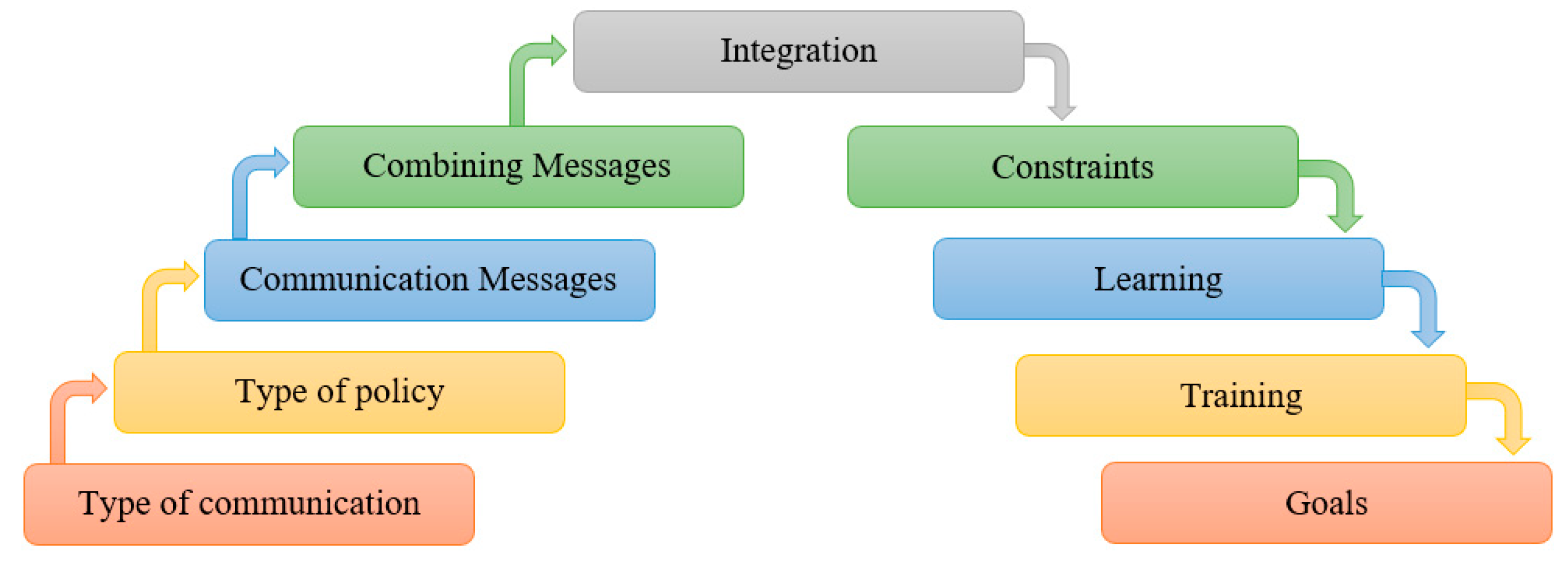
Figure 5.
Communication process of the Comm-MARL.

Figure 6.
Agents’ communication based on the multiagent neighbor-to-neighbor.
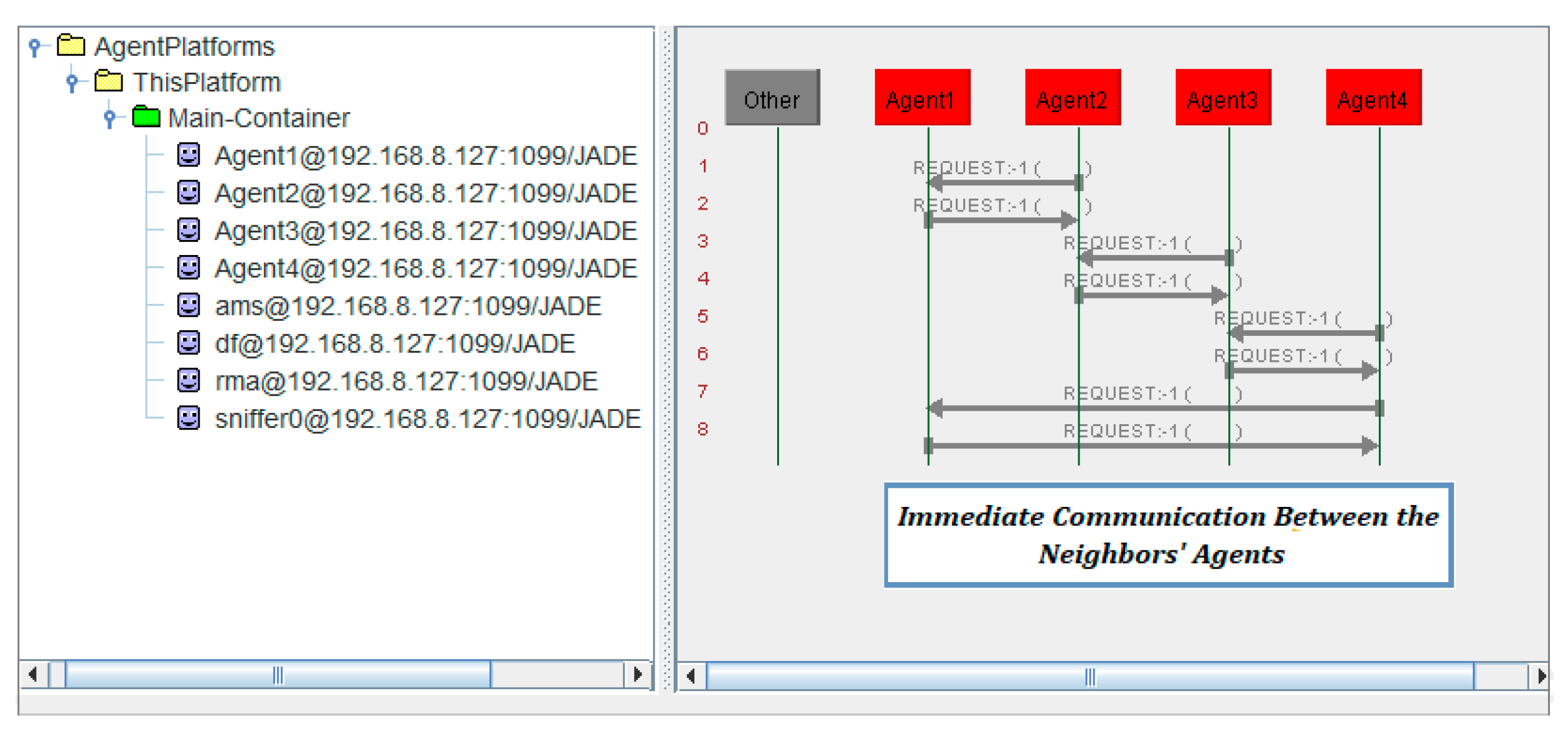
Figure 7.
A DC autonomous microgrid of 48 V and the (N) number of decentralized BESS agents, with the existence of a multiagent neighbor–to–neighbor transfer of information and the measured DC impact of the infrastructure branches.
Figure 7.
A DC autonomous microgrid of 48 V and the (N) number of decentralized BESS agents, with the existence of a multiagent neighbor–to–neighbor transfer of information and the measured DC impact of the infrastructure branches.
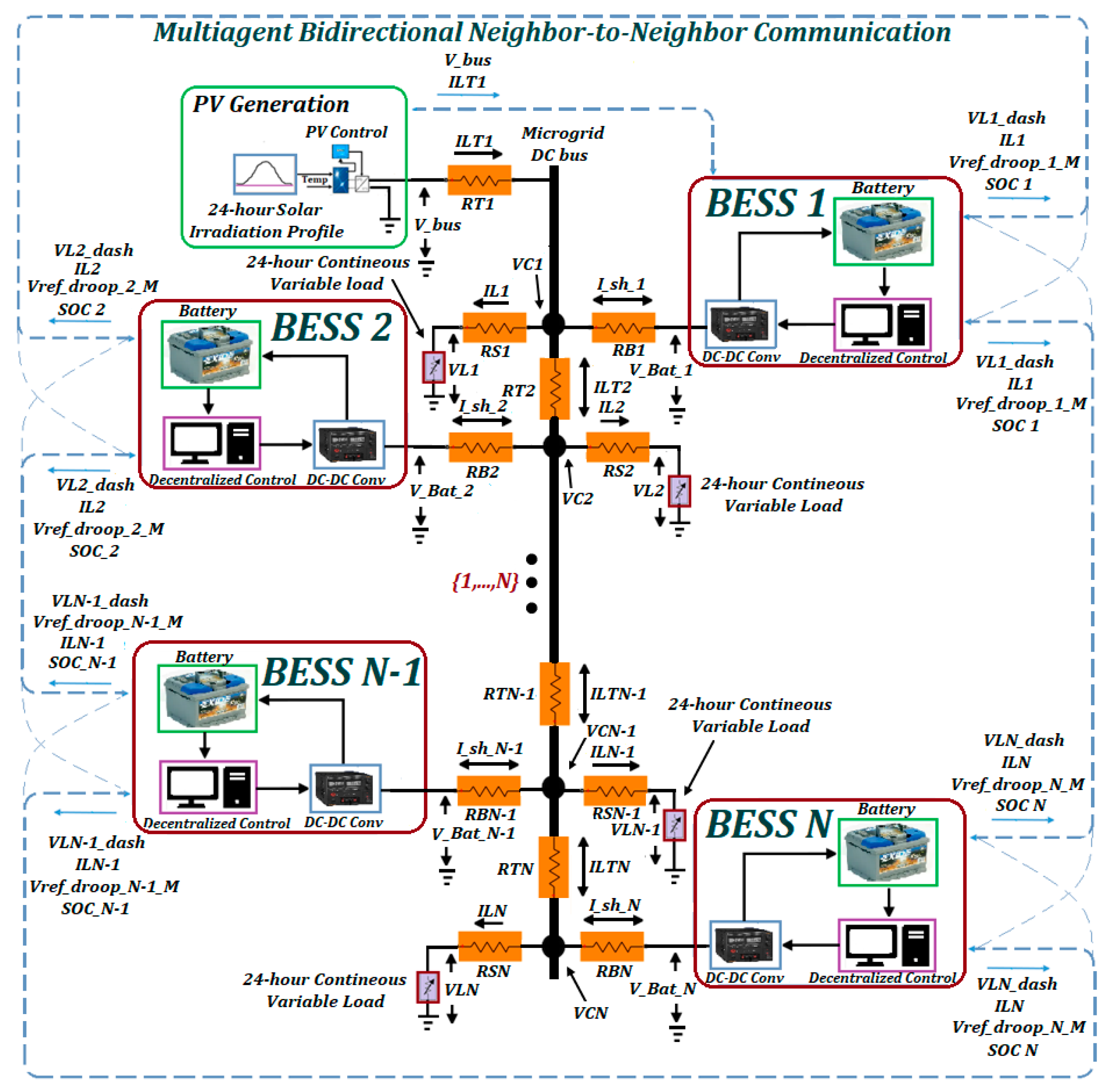
Figure 8.
The real–time decentralized multiagent-based compensation of the DC infrastructure influence on the control process.
Figure 8.
The real–time decentralized multiagent-based compensation of the DC infrastructure influence on the control process.

Figure 9.
The primary power regulation under the existence of the infrastructure impact.
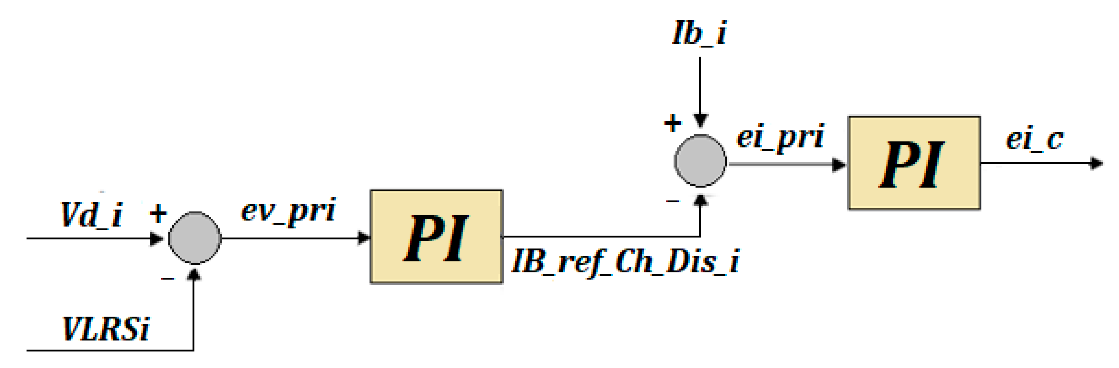
Figure 10.
A distributed battery-energy-storage system under the proposed adaptive decentralized primary–secondary control strategy.
Figure 10.
A distributed battery-energy-storage system under the proposed adaptive decentralized primary–secondary control strategy.
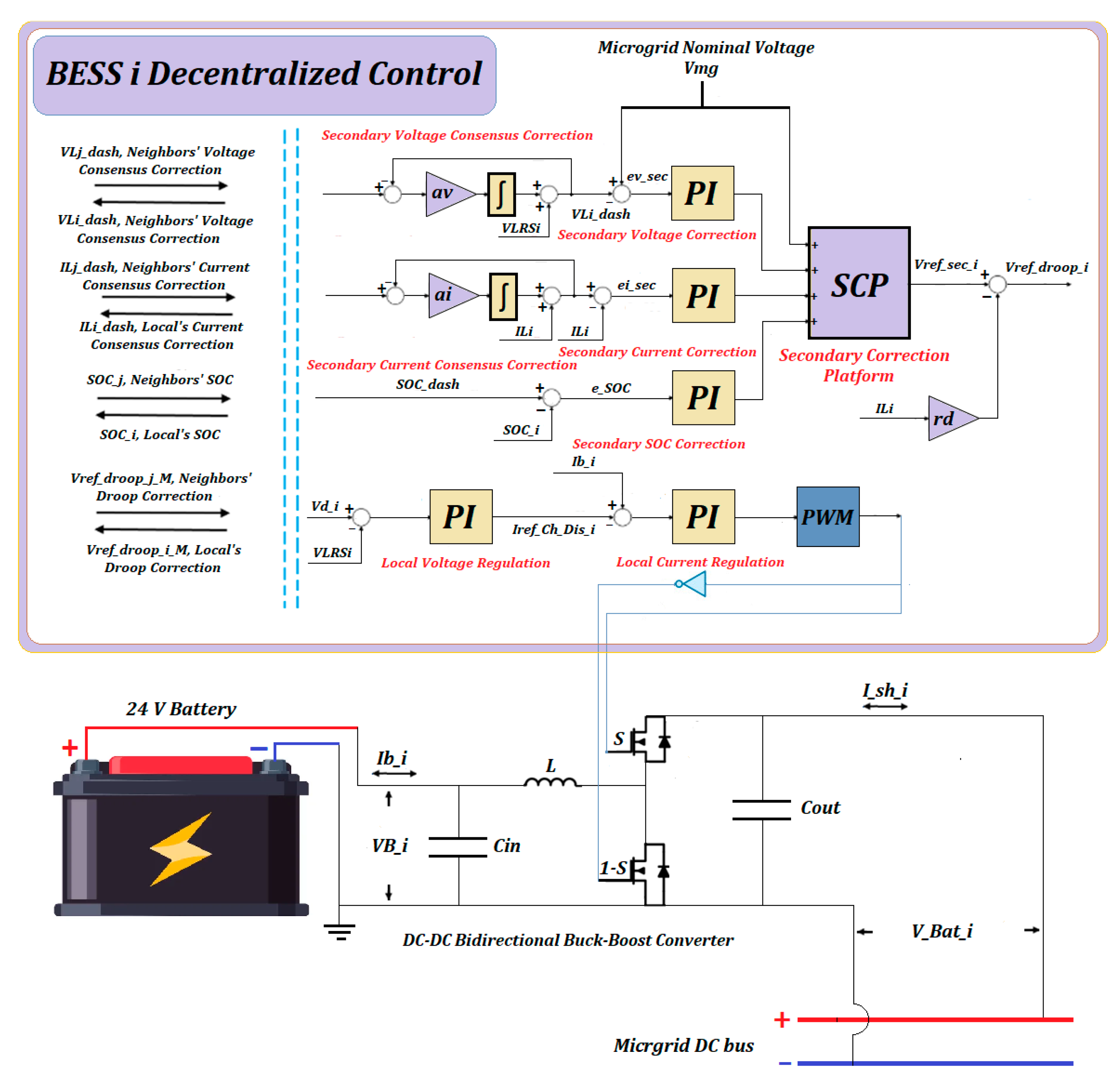
Figure 11.
The secondary voltage consensus correction with the compensation of the infrastructure influences.
Figure 11.
The secondary voltage consensus correction with the compensation of the infrastructure influences.

Figure 12.
The topology of the multiagent transfer of information, plug-and-play policy, and the coordination of the neighbors’ BESSs.
Figure 12.
The topology of the multiagent transfer of information, plug-and-play policy, and the coordination of the neighbors’ BESSs.
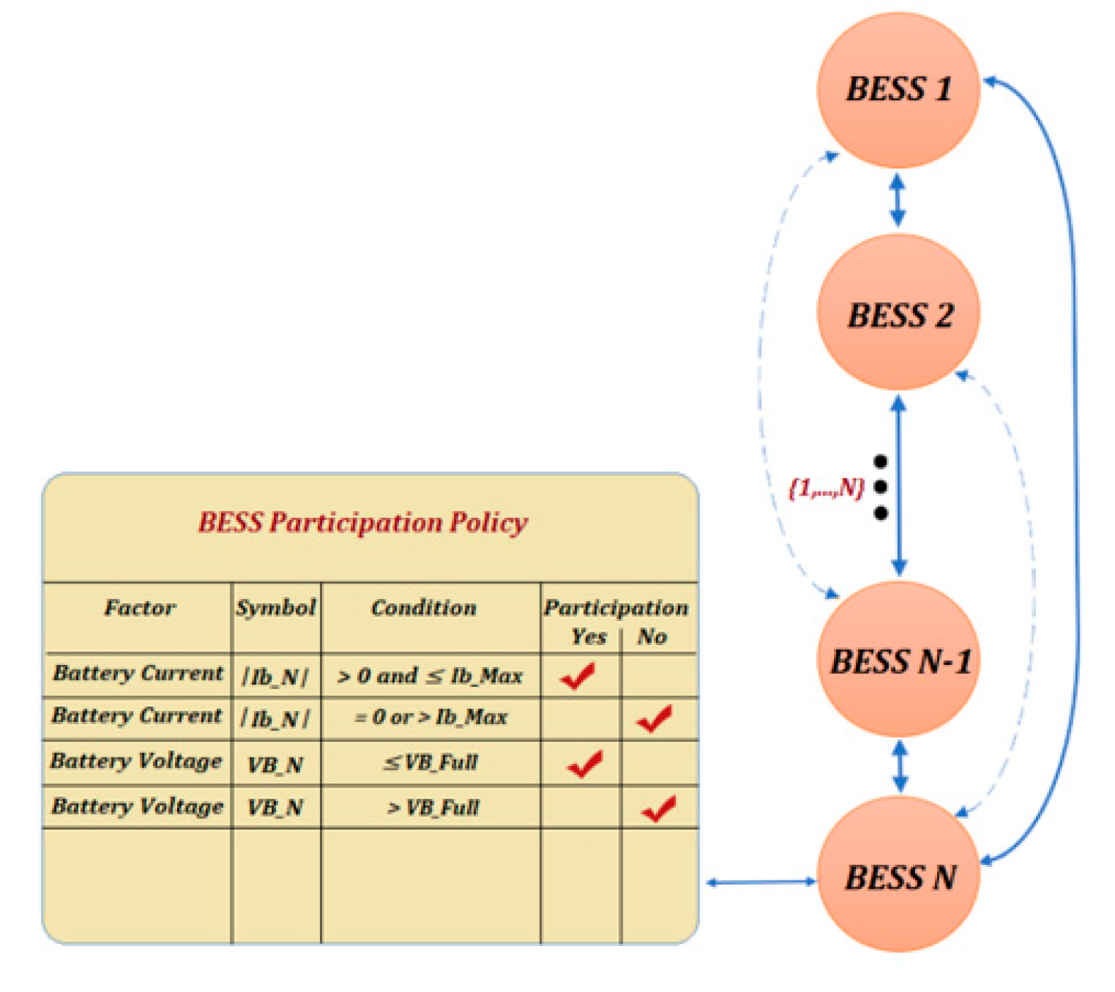
Figure 13.
Case 1 results: (a) SOC and output voltage by the existing strategy; (b) SOC and output voltage under the suggested adaptive strategy with the compensation of the DC influence; (c) The implementation of 24 h excessive continuous variations in the load; (d) 24 h profile of PV generation.
Figure 13.
Case 1 results: (a) SOC and output voltage by the existing strategy; (b) SOC and output voltage under the suggested adaptive strategy with the compensation of the DC influence; (c) The implementation of 24 h excessive continuous variations in the load; (d) 24 h profile of PV generation.

Figure 14.
Case 1 line chart of the output voltage measurements under the existing/proposed strategies.
Figure 14.
Case 1 line chart of the output voltage measurements under the existing/proposed strategies.

Figure 15.
Case 1 24 h total power consumption: (a) A line chart demonstrating the measured total power consumption during 24 h operation of the existing strategy (the blue line) and proposed strategy (the orange line). (b) A bar chart highlighting the reduction in the total power consumption by the suggested adaptive approach compared to the existing strategy.
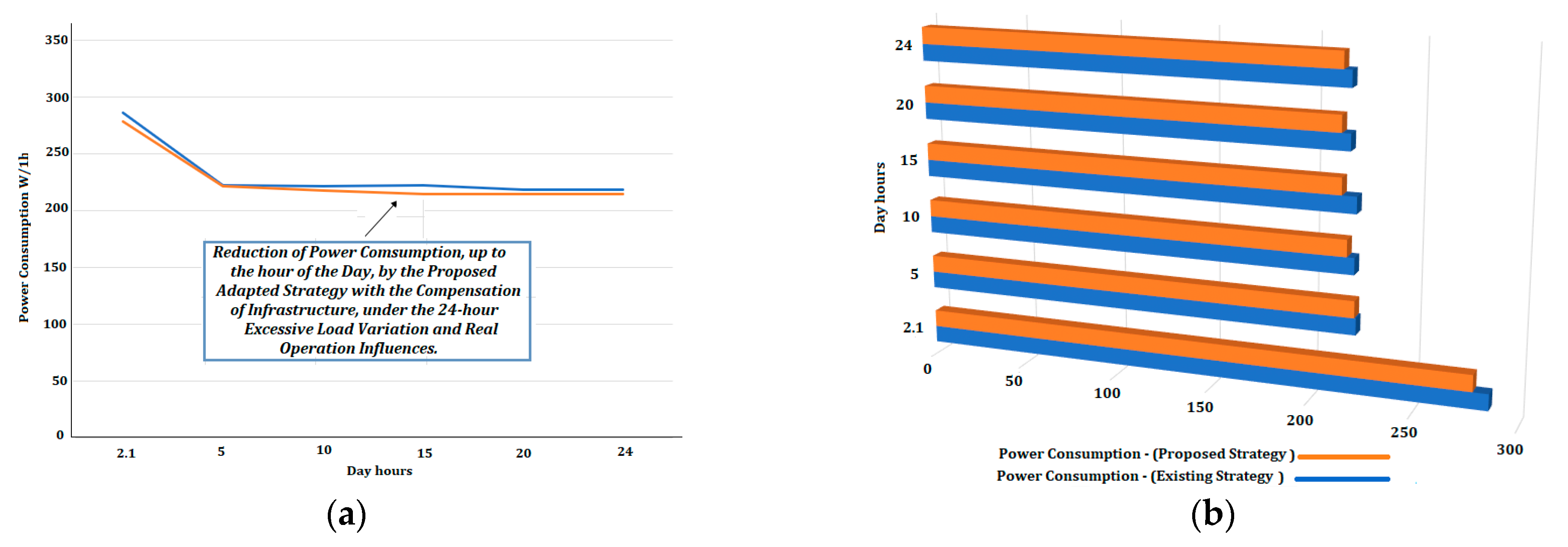
Figure 16.
Case 1 24 h power flow: (a) A line chart demonstrating the measured power-flow balance during 24 h of the existing strategy (the blue line) and proposed strategy (the orange line). (b) A bar chart highlighting the enhancement of the power-flow balance under the suggested approach.
Figure 16.
Case 1 24 h power flow: (a) A line chart demonstrating the measured power-flow balance during 24 h of the existing strategy (the blue line) and proposed strategy (the orange line). (b) A bar chart highlighting the enhancement of the power-flow balance under the suggested approach.
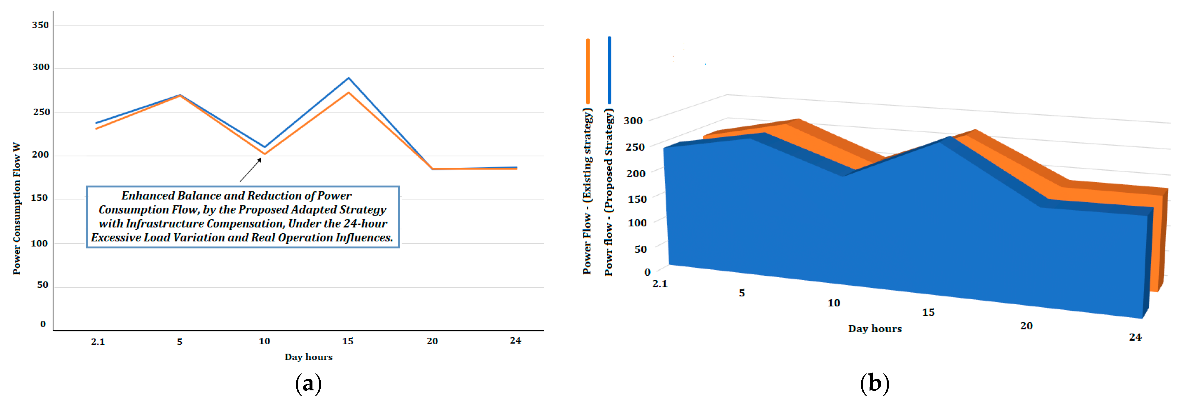
Figure 17.
Case 2 results, with presentation of the times for each plug-and-play period: (off-participation, a1–a12), (participation, b1–b12), and (convergence, c1–c12), as demonstrated in Table A4: (a) SOC and output voltage of the existing control; (b) SOC and output voltage of the suggested adaptive approach; (c) Unbalanced implementation of 24 h excessive continuous load by the existing strategy; (d) Balanced 24 h hour excessive continuous load by the proposed adapted strategy with the compensation of the infrastructure influence.
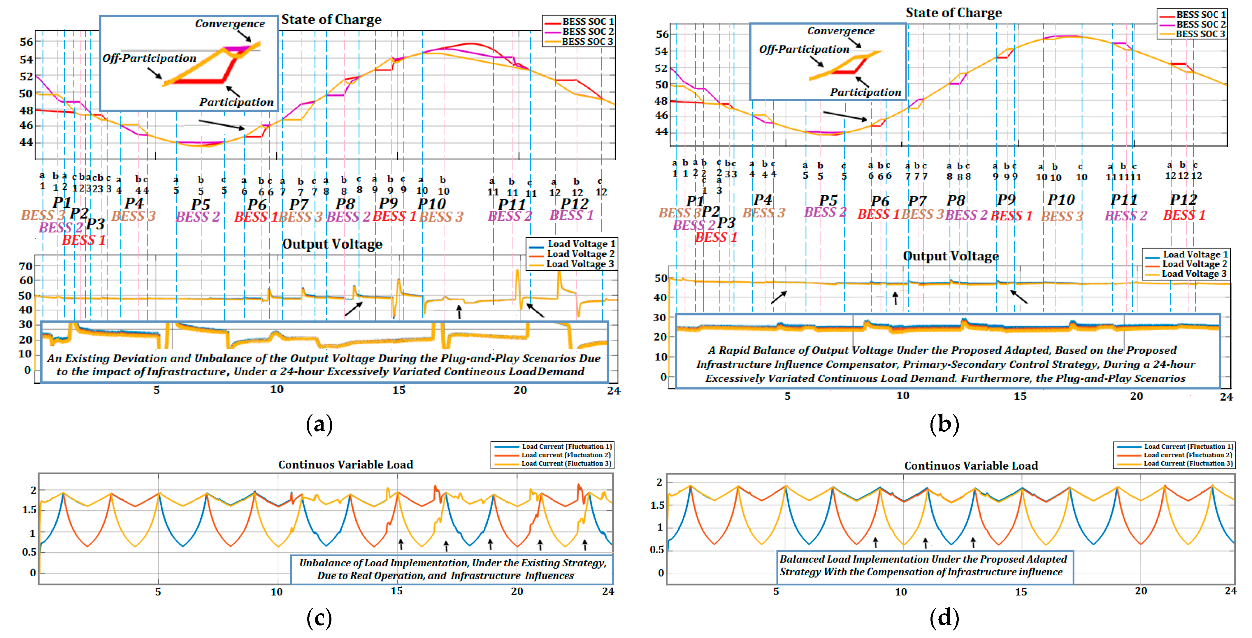
Figure 18.
Case 2 plug-and-play convergence time comparison of the existing/proposed strategies.

Figure 19.
Case 2 plug-and-play comparison of the output voltage balance between the existing and proposed adaptive strategy.
Figure 19.
Case 2 plug-and-play comparison of the output voltage balance between the existing and proposed adaptive strategy.

Figure 20.
Case 2 plug-and-play power consumption demonstration: (a) A line chart showing the measured power consumption during the 24 h operation for the existing strategy (the orange line) and proposed strategy (the grey line). (b) A bar chart highlighting the outperformance of the proposed adaptive strategy in terms of power-consumption reduction.
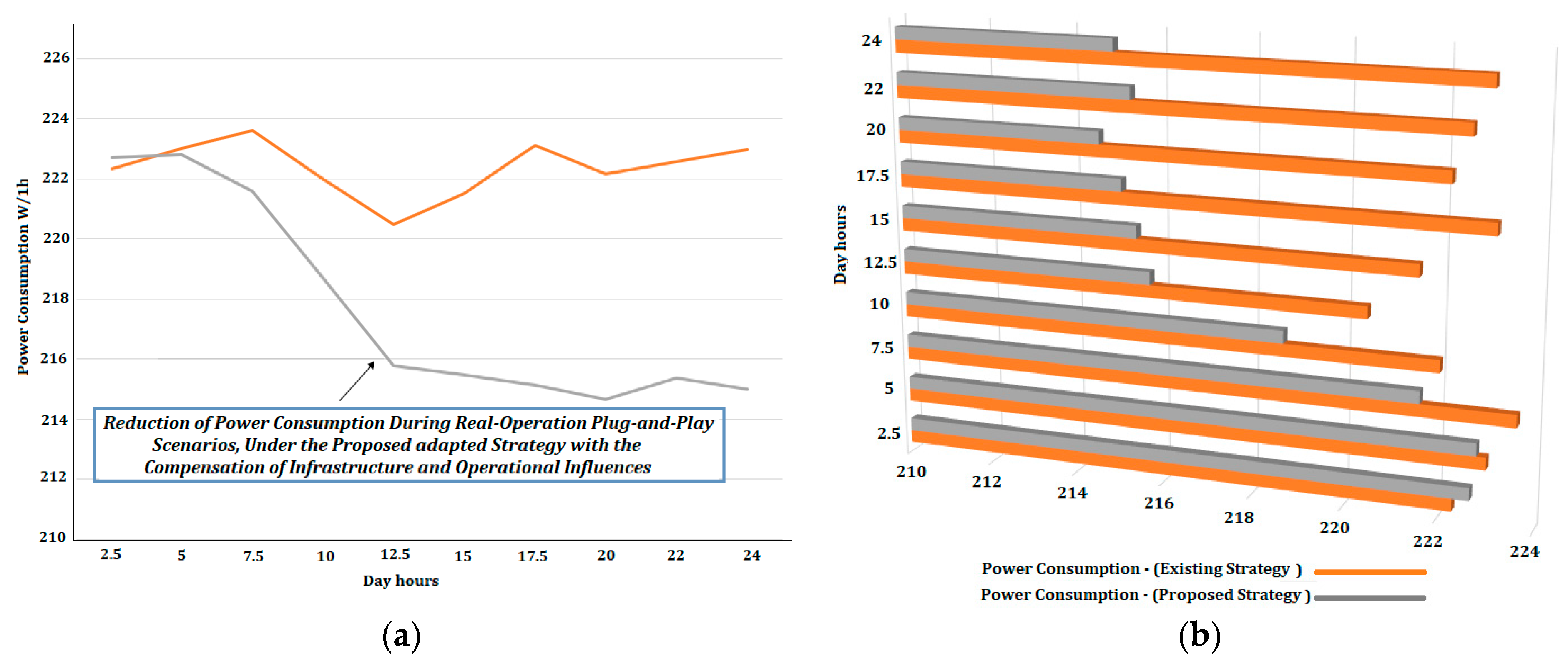
Figure 21.
Case 2 plug-and-play power flow demonstration: (a) A line chart showing the measured power flow during 24 h of the existing strategy (the orange line) and proposed strategy (the grey line). (b) A bar chart highlighting the outperformance of the proposed adapted strategy in terms of the power-flow balance.

Table 1.
Parameters and factors of the case studies.
| Parameters and Factors | Symbol | Value |
|---|---|---|
| Voltages, Nominal/Battery | 48, 24 V | |
| Nominal Current of Batteries | 3.913–4.782 A | |
| Batteries’ Maximum Capacity | 9–11 Ah | |
| Converter Capacitances | 125–1000 µf | |
| Converter Inductance | L | 2.4 mH |
| Switching Frequency | 5 KHz | |
| Local Voltage Control Proportional/Integral Gains | 0.85, 10 | |
| Local Current Control Proportional/Integral Gains | 0.1, 10 | |
| Droop Coefficient | rd | 0.5 |
| SOC Correction Proportional/Integral Gains | 0.4, 20 | |
| Secondary Voltage Correction Proportional/Integral Gains | 10, 0.5 | |
| Secondary Current Correction Proportional/Integral Gains | 0.4, 20 | |
| Consensus Gains | 10, 20 |
Table 2.
Case studies of the DC infrastructure influence of the microgrid branches.
| Branch | Symbol | Value/Ω |
|---|---|---|
| Entry 1: Transmission connection between the renewable resource and the DC microgrid bus | 0.06 | |
| BESS 1 line | 0.04 | |
| Load 1 line | 0.05 | |
| Transmission connection between the BESS 1 and BESS N − 1 | 0.06 | |
| BESS N − 1 line | 0.05 | |
| Load N − 1 line | 0.03 | |
| Transmission connection between the BESS N − 1 and BESS N | 0.04 | |
| BESS N line | 0.03 | |
| Load N line | 0.04 |
Disclaimer/Publisher’s Note: The statements, opinions and data contained in all publications are solely those of the individual author(s) and contributor(s) and not of MDPI and/or the editor(s). MDPI and/or the editor(s) disclaim responsibility for any injury to people or property resulting from any ideas, methods, instructions or products referred to in the content. |
© 2023 by the authors. Licensee MDPI, Basel, Switzerland. This article is an open access article distributed under the terms and conditions of the Creative Commons Attribution (CC BY) license (https://creativecommons.org/licenses/by/4.0/).
Share and Cite
MDPI and ACS Style
Al-Saadi, M.; Short, M. Multiagent-Based Control for Plug-and-Play Batteries in DC Microgrids with Infrastructure Compensation. Batteries 2023, 9, 597. https://doi.org/10.3390/batteries9120597
AMA Style
Al-Saadi M, Short M. Multiagent-Based Control for Plug-and-Play Batteries in DC Microgrids with Infrastructure Compensation. Batteries. 2023; 9(12):597. https://doi.org/10.3390/batteries9120597
Chicago/Turabian StyleAl-Saadi, Mudhafar, and Michael Short. 2023. "Multiagent-Based Control for Plug-and-Play Batteries in DC Microgrids with Infrastructure Compensation" Batteries 9, no. 12: 597. https://doi.org/10.3390/batteries9120597
Note that from the first issue of 2016, this journal uses article numbers instead of page numbers. See further details here.