
Construction of Fe3O4@Fe2P Heterostructures as Electrode Materials for Supercapacitors

Research School of Polymeric Materials, School of Materials Science & Engineering, Jiangsu University, Zhenjiang 212013, China
*
Author to whom correspondence should be addressed.
Batteries 2023, 9(6), 326; https://doi.org/10.3390/batteries9060326
Submission received: 1 June 2023
/
Revised: 12 June 2023
/
Accepted: 13 June 2023
/
Published: 15 June 2023
(This article belongs to the Special Issue Advanced Materials for High-Performance Supercapacitors and Battery Applications)
Abstract
:Considering their high abundance in the earth, iron-based materials have occasionally been regarded as promising electrode materials for supercapacitors. However, monometallic iron-based electrodes still demonstrate an insufficient specific capacitance value in comparison to monometallic Mn-, Ni-, and Co-based compounds and their combined materials. Herein, an enhanced iron-based heterostructure of Fe3O4@Fe2P was prepared via the in situ phosphorization of Fe3O4. Compared to pristine Fe3O4, the Fe3O4@Fe2P heterostructure showed a capacity enhancement in KOH aqueous solution. The improved electrochemical performance can be attributed to both the core shell structure, which favors buffering the collapse of the electrode, and the synergistic effect between the two iron compounds, which may provide abundant interfaces and additional electrochemically active sites. Moreover, the assembled asymmetric supercapacitor device using the Fe3O4@Fe2P heterostructure as the positive electrode and activated carbon as the negative electrode delivers a high energy density of 13.47 Wh kg−1, a high power density of 424.98 W kg−1, and an acceptable capacitance retention of 78.5% after 5000 cycles. These results clarify that monometallic Fe based materials can deliver a potential practical application. In addition, the construction method for the heterostructure developed here, in which different anion species are combined, may represent a promising strategy for designing high-performance electrodes.
1. Introduction
Among the various types of energy storage devices, supercapacitors and batteries have a wide range of applications and receive much attention. Compared with batteries, supercapacitors have become an influential energy storage device with the advantages of high power density, fast charging and discharging, good cycle stability, and high operational safety [1,2,3]. The inherent properties of electrode materials are important factors affecting the energy storage performance of supercapacitors, and, so far, the widely used materials for supercapacitors are carbon materials [4,5], metal oxides [6], and conducting polymers [7]. Among these materials, RuO2 is reported to be one of the excellent candidates for the electrode materials for supercapacitors due to its high conductivity and high capacity [8]. However, its toxicity and high cost limit its practical application in industry. Among the many metal oxides, iron oxides have become an alternative material to RuO2 in supercapacitors and have gained widespread attention due to their various three-dimensional electronic configurations and different morphological and physical phase compositions [9]. For example, Li et al. attached Fe3O4 nanosheet arrays to Fe wires and obtained Fe3O4 nanosheet arrays with a specific capacitance of 20.8 mF cm−1 at 10 mV s−1 and a retention rate of 91.7% after 2500 cycles [10]. Tang et al. synthesized layered heterostructures of Fe3O4@Fe2O3 core-shell nanorod arrays (NRAs) by solvothermal and electrodeposition processes, showing large bulk capacitance (1206 F/cm3) with a good rate capability and cycling stability [11].
However, most transition metal oxides have poor electrical conductivity and durability, so researchers have begun to focus on some metal oxide derived materials, such as transition metal sulfides [12], phosphides [13], selenides [14], and nitrides [15], among which transition metal phosphides (TMPs) have become good conductors of heat and electricity due to their strong mechanical hardness and stability [16]. When transition metals are combined with elemental phosphorus due to the lower electronegativity of phosphorus, the bond ions are reduced, resulting in better metal-like properties than metal carbides and nitrides. TMPs with different microstructures were explored; for example, Wei et al. designed CoP nanocubes with a specific capacitance of 600 F g −1 at 1 A g−1 current density [17]. Cuña et al. prepared carbon nanocomposites containing iron/phosphorus compounds via porous carbon, exhibiting enhanced specific capacitance up to 447 F g−1 at 10 A g−1 and good multiplicative properties [18]. Recently, some heterostructured materials were also widely investigated for energy storage devices. In particular, van der Waals layered heterostructured materials can provide a large number of active sites, accelerate the contact between the electrode material and the electrolyte, and improve ion transfer kinetics [19,20]. Therefore, the rational design of materials with heterogeneous structures is extremely important to improve the performance of electrode materials for energy storage devices. So far, heterostructured materials are widely used in fields such as electrocatalysis, while they are less reported in energy storage fields such as supercapacitors. To form monometallic iron heterostructures, which require the exploration of interfaces composed of a single metal and different anions, remains a challenge.
In this experiment, spherical Fe3O4 was first prepared by the solvothermal method and then phosphorylated in a tube furnace to obtain the Fe3O4@Fe2P heterostructure. The heterostructure was subjected to a series of structural and morphological characterizations and applied to a supercapacitor as a working electrode for a series of electrochemical tests. The electrochemical performance of the Fe3O4@Fe2P heterostructure is significantly better than that of Fe3O4 in the three-electrode system, with a specific capacitance of 651.25 F g−1 at 0.5 A g−1. When Fe3O4@Fe2P is composed of asymmetric supercapacitor devices with activated carbon (AC), it exhibits excellent capacitive behavior with a power density of 424.98 W Kg−1 at a maximum energy density of 13.47 Wh Kg−1 and a capacitance loss of only 21.5% after 5000 cycles at 6 A g−1, with an excellent capacitance retention rate, showing good cycling stability. Finally, after a full charge, two sets of all-solid-state asymmetric supercapacitors connected in series can light up a red LED and keep it lit for one minute, showing good commercial potential.
2. Experimental Section
2.1. Materials
The reagents used in this experiment were all of analytical grade and did not need to be purified. Ferric chloride hexahydrate (FeCl3·6H2O), anhydrous sodium acetate (CH3COONa), polyethylene glycol (PEG), and sodium hypophosphite (NaH2PO2) were purchased from Sinopharm Chemical Reagent Co., Ltd., Ningbo, China. Ultra-high-capacity porous carbon activated carbon (AC) with a specific surface area of 2000 m2 g−1 and a particle size of 10 μm was purchased from Aladdin, and ethylene glycol (EG) was purchased from Shanghai Maclean Biochemical Technology Co., Ltd. (Shanghai, China).
2.2. Synthesis of Fe3O4@Fe2P
2.2.1. Preparation of Fe3O4
First, 1.35 g of FeCl3.6H2O, 3.6 g of anhydrous sodium acetate (CH3COONa) and 1.0 g of polyethylene glycol (PEG) were weighed, dissolved in 40 mL of ethylene glycol (EG), sonicated for 30 min, and stirred at room temperature to mix the solution well. The above mixture solution was then transferred to 100 mL of PTFE liner, loaded into a stainless steel reactor, screwed on, and reacted at 200 °C for 10 h. After the reaction kettle was cooled to room temperature, the product was centrifuged and washed more than three times with deionized water and ethanol. Finally, the target product Fe3O4 was obtained by vacuum drying in a vacuum-drying oven at 60 °C overnight.
2.2.2. Preparation of Fe3O4@Fe2P Heterostructure
First, 0.2 g sodium hypophosphite (NaH2PO2) and 0.1 g Fe3O4 were placed in two porcelain boats, respectively, in the upper and lower reaches of the tubular furnace. Under the protection of N2 atmosphere, the final product Fe3O4@Fe2P heterostructure was obtained by calcination for 2 h in the tubular furnace at 350 °C.
2.3. Characterization
The crystal structure and phase composition of the samples were tested and analyzed by X-ray diffraction (XRD) with a sweep speed of 8°/min and a test range of 10° to 80°. Surface morphology and internal structure of the samples were analyzed by field emission scanning electron microscopy (SEM) and transmission electron microscopy (TEM). The fully automated specific surface area and pore size of the samples were tested by Brunau-er–Emmett–Teller (BET) with full pore test conditions. The elemental composition and chemical valence of the samples were analyzed by X-ray photoelectron spectroscopy (XPS).
2.4. Electrochemical Measurements
Electrochemical experimental tests (including EIS, CV, GCD, and cycling performance tests for two or three electrodes) were performed. In the three-electrode system, Fe3O4@Fe2P was used as the working electrode, Pt sheet electrode as the auxiliary electrode, and saturated glycury electrode as the reference electrode, and the electrolyte was 1 mol/L KOH aqueous solution [21]. The working electrodes were prepared as follows. Firstly, the pretreatment of nickel foam was carried out, and the nickel foam was cleaned in acetone and 1 mol/L aqueous hydrochloric acid, deionized, ultrasonicated in hydrous ethanol for 10 min, and then dried under vacuum at 60 °C overnight. Subsequently, the working electrode was prepared by weighing 15 mg of active substance sample, 3 mg of acetylene black, and 2 mg of PVDF (mass ratio 75:15:10); mixing well with a mortar and pestle; adding 3 drops of 1-methyl-2-pyrrolidone (NMP); uniformly grinding into a slurry; and then applying the slurry to 1 × 1 cm square of nickel foam. Then, it was dried under vacuum at 60 °C for 12 h. Finally, the working electrode was obtained by pressing the nickel foam under the pressure of 25~30 MPa, and finally the coated slurry was partially soaked in 1 mol/L KOH aqueous solution for more than three hours for pre-activation. The activated carbon electrode was made using the same process as the sample electrode.
In addition, to prepare a two-electrode system, asymmetric supercapacitors (Fe3O4@Fe2P||AC) were assembled with activated carbon (AC) selected from KOH/PVA as the gel electrolyte. The specific capacitance [22] (C, F g−1), energy density (E, W h kg−1), and power density [23] (P, W kg−1) were calculated as follows:
where I, Δt, m, and ΔV represent current density, discharge time, mass load, and voltage window, respectively.
3. Results and Discussion
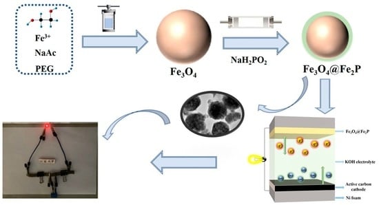
In this experiment, Fe3O4 was first synthesized by the solvothermal method, with ethylene glycol (EG) as the solvent and FeCl3·6H2O as the only iron source. NaAc not only played the role of dispersant but also played the role of structural guide. The amount of NaAc in the reaction can control the size of the Fe3O4 particles. Since NaAc can form an electrostatic balance in the system, electrostatic repulsion and steric hindrance can be generated between the static and growing particles. Therefore, NaAc acted as a dispersant in the reaction system. PEG molecules as polymers can be bonded to the surface of Fe3O4 particles by hydrogen bonding when dissolved in EG. The formation of Fe3O4 involved the following reaction equation [24]:
FeCl3·6H2O + NaAc + HOCH2CH2OH → Fe3O4
Then, the Fe3O4 and NaH2PO2 formed the Fe3O4@Fe2P heterostructure by the solid-phase phosphating method. NaH2PO2 can be decomposed to produce PH3 gas at 350 °C, and PH3 was deposited on Fe3O4 by the flow of N2. The surface of Fe3O4 was partially phosphated with PH3 gas to form the Fe3O4@Fe2P heterostructure, as shown in Figure 1.
The composition and crystal structure of the samples were analyzed by XRD, as shown in Figure 2. The diffraction peak of the Fe3O4 intermediate was sharp, which indicated that it has good crystallinity. In addition, the diffraction peak angle and intensity were basically consistent with the XRD standard card (JCPDS No.19-0629). The diffraction peaks at 2θ = 35.42°, 56.94°, and 62.52° corresponded to the (311), (511), and (440) crystal planes of Fe3O4, respectively. From the burr of the diffraction peak, we can see that the purity of Fe3O4 was not very good. The reason may be that some unwashed impurities interfered with the diffraction peak. The Fe3O4@Fe2P sample after phosphating treatment had a small amount of Fe3O4 diffraction peaks, and the intensity was slightly weakened. There were other weak peaks. It was found that it was in good agreement with the XRD standard card of Fe2P (JCPDS No.27-1171) after comparison, and the intensity was slightly weakened. The reason may be that the degree of phosphating or the diffraction peak of Fe3O4 magnetic interference was not enough.
Figure 3 shows the microscopic morphology of the samples before and after phosphorylation by field emission scanning electron microscopy (SEM). Figure 3a–c are the SEM images of Fe3O4 at different magnifications. Fe3O4 self-assembled nanospheres under solvothermal conditions can be seen by electron microscopy. The Fe3O4 nano–microspheres were relatively uniformly distributed, and the size was maintained at about 300 nm. Different degrees of pores can also be observed on the surface, which greatly increased their specific surface area. The SEM images of the Fe3O4@Fe2P sample after partial phosphating are shown in Figure 3b–d, which basically maintained the spherical structure, indicating that the high-temperature calcination during the phosphating treatment did not cause too much damage to the structure of Fe3O4. In addition, the surface of Fe3O4 nanospheres was observed to a layer of flocculent material, which may be due to the partial phosphide Fe2P left during the phosphating treatment.
The internal structure of the sample can be further characterized by TEM test, as shown in Figure 4. Figure 4a–c show the TEM images of Fe3O4 at different magnifications, showing a spherical shape with a uniform size; the size was about 300 nm. As opposed to the SEM of our previously analyzed samples, it can be seen that there were pores of different sizes internally distributed, showing a clear porous structure. Figure 4c is a high-magnification TEM. It can be clearly seen that the interplanar spacing was 0.469 nm. After comparison, it was found that it corresponded to the (111) crystal plane of Fe3O4 (JCPDS No.19-0629), which further proved the conclusion of XRD. Figure 4d–f show the TEM image of the sample after phosphating; it still remained spherical after phosphating, and the spherical surface was covered with a layer of flocculent material, which may be the new product Fe2P after partial phosphating. Figure 4f is a high-magnification TEM. From the picture, the clear boundary can be seen; the part with lattice fringes in the middle was Fe3O4, and the edge part was Fe2P, which proves this was Fe3O4@Fe2P with a heterostructure.
To further verify the porous structure of the samples, the samples were analyzed by N2 adsorption–desorption experiments to determine the specific surface area and pore size distribution of the samples, as shown in Figure 5. The shapes of the N2 adsorption–desorption curves of the samples before and after phosphorylation remained consistent. In addition, there was a clear hysteresis loop (Figure 5a). The specific surface area of the original Fe3O4 sample was only 2.22 m2 g−1, and, as the reaction proceeded, the hysteresis loop of the phosphorylated sample increased, and the specific surface area reached 7.10 m2 g−1, probably because the calcination during phosphorylation caused a certain expansion effect on the spherical structure. From Figure 5b, it is easy to see that the two samples mainly consisted of mesoporous structures of 20–50 nm, while the Fe3O4@Fe2P samples also had a small number of microporous structures of 1–2 nm, further indicating that the Fe3O4@Fe2P heterogeneous structure had more abundant pore structures than Fe3O4, which greatly increased the effective electrode material and electrolyte during the electrochemical test. Moreover, the rich pore structure can also provide a large number of active sites for reversible redox and form fast-diffusion channels for ions, thus improving its electrochemical performance.
In order to further characterize the chemical element state of the sample, the Fe3O4@Fe2P heterostructure was selected for the XPS test; as shown in Figure 6, the full spectrum (Figure 6a) shows that the selected sample has three elements: Fe, O, and P. Figure 6b shows that the Fe 2p spectrum can be divided into two peaks at 713.28 and 727.18 eV, proving the existence of Fe3+, and two peaks at 710.78 and 724.48 eV, proving the existence of Fe2+. In the O 1s high-resolution spectrum (Figure 6c), three peaks at different positions were fit, 530.78, 531.38, and 531.88 eV, which correspond to Fe-O, P-O, and O-H, respectively. Figure 6d shows the high-resolution spectrum of P 2p, which is mainly fit with two peaks of P-O and Fe-P. Based on the above XPS peak separation results, it can be concluded that the product after phosphating was the Fe3O4@Fe2P heterostructure.
In order to analyze the electrochemical performance of the prepared electrode material samples in supercapacitors, a three-electrode system was assembled with a 1 M KOH aqueous solution as the electrolyte and Fe3O4 and Fe3O4@Fe2P as the working electrodes for performance testing. Figure 7a–c show the comparison of Fe3O4 and Fe3O4@Fe2P in EIS, CV, and GCD tests, respectively. The radius size of the semicircle in the high frequency region represented the transfer resistance of electrons, and it can be seen from Figure 7a that the semicircle radius of the Fe3O4@Fe2P electrode was smaller than that of Fe3O4, indicating that the phosphorylated Fe3O4@Fe2P sample had a smaller charge transfer resistance, while the slope size of the straight line in the low frequency region showed the diffusion resistance size; and it can be seen from Figure 7a that the slope of the Fe3O4@Fe2P electrode was steeper compared to that of the Fe3O4 sample, which also confirmed that the Fe3O4@Fe2P electrode had a smaller diffusion resistance. In general, the resistance of Fe3O4@Fe2P was smaller, which as more conducive to the electron transfer of the electrode material in the electrolyte transfer and ion diffusion, with more excellent electrochemical properties. Figure 7b shows the CV curves of both electrode materials at a scan rate of 100 mV s−1, with a pair of obvious symmetric redox peaks in the voltage range of 0~0.7 V, showing good pseudocapacitance characteristics. Figure 7c shows the GCD curves of both samples at 0.5 A g−1, showing asymmetric linearity and obvious plateaus of charge and discharge potentials and further demonstrating the pseudocapacitive behavior of the electrode materials, and the data showed that the Fe3O4@Fe2P electrode had a longer discharge time and larger specific capacitance. Considering the results of EIS, CV, and GCD analysis together, the Fe3O4@Fe2P material exhibited superior electrochemical performance. Therefore, the electrochemical properties of Fe3O4@Fe2P electrode materials are separately analyzed in Figure 7d–f. Figure 7d shows the CV curves of Fe3O4@Fe2P at different scan rates. From Figure 7d, it can be seen that the CV curve area gradually increased with the increase in sweep rate, and the curve almost kept the initial shape. Even at the maximum sweep rate of 100mVs−1, obvious redox peak can still be observed, which indicated that Fe3O4@Fe2P has good stability and rate performance during the charging and discharging process. It is noteworthy that the position of the redox peak gradually and slightly shifted in the higher/lower direction as the sweep speed increased, which may be due to the electrode material generated by the polarization phenomenon in the electrolyte at high sweep speeds. Figure 7e shows the GCD curves of Fe3O4@Fe2P electrode materials at different current densities, all with obvious charge/discharge potential plateaus, which also verified the conclusion of the CV curves. The specific capacitance was calculated to be 651.25 Fg−1 at 0.5 A g−1. As shown in Table 1, the specific capacitance of Fe3O4@Fe2P was compared with other similar electrode materials under this operating condition. The excellent electrochemical properties of Fe3O4@Fe2P materials may be attributed to the formation of interfacial heterostructures with different sized pore channels, which provide abundant redox reaction active sites’ accelerated electron transfer and formation of fast-diffusion channels for ions. Based on this, the specific capacitance of Fe3O4@Fe2P electrode materials is higher than that of the other similar electrode materials listed in Table 1.
The two-electrode test is an important tool to analyze the effectiveness of the material for practical applications. By comparing Fe3O4 and Fe3O4@Fe2P electrodes, it was found that the Fe3O4@Fe2P heterostructure was superior to Fe3O4 in terms of morphology, structure, and electrochemical properties. Therefore, Fe3O4@Fe2P and activated carbon (AC) were made into electrodes and assembled into asymmetric supercapacitors (Fe3O4@Fe2P||AC), and the electrochemical performance was tested in 1 M KOH solution, as shown in Figure 8. Figure 8a shows the CV curves of the electrode materials by changing the voltage window at a 100 mV s−1 sweep rate, and the CV curve shape was almost the same as the initial one when the voltage window was increased from 0.8 V to 2 V, indicating that the Fe3O4@Fe2P||AC asymmetric electrode had good stability, and there was no serious polarization phenomenon (Figure 8b). By changing the scan speed by selecting the voltage window from 0 to 2 V, the area of the closed graph formed by the CV curve increased with the increase in the scan speed; the CV curve shape also remained stable, showing the fast electron transport; and the behavioral characteristics of the combined layer capacitance and pseudocapacitance can be observed. Figure 8c shows the GCD curves at different current densities. The specific capacitance of the Fe3O4@Fe2P||AC double electrode was calculated according to Equation (1), as shown in Figure 8d. According to Equations (2) and (3), the power density and energy density of Fe3O4@Fe2P||AC were calculated, as shown in Figure 8e, with a maximum energy density of 424.98 W kg−1 at 13.47 Wh kg−1. Finally, the device lost only 21.5% of its cycling capacitance after 5000 cycles at 6 A g−1, showing stable cycling performance, as shown in Figure 8f. In addition, Table 2 lists the comparison of the cycling stability of Fe3O4@Fe2P-based supercapacitor devices reported in recent years, and it can be seen that the Fe3O4@Fe2P prepared in this experiment had obvious advantages. Among them, the inset of Figure 8f shows that two pairs of all-solid-state asymmetric supercapacitors can be connected in series to light up a red LED, indicating that the electrode material has a strong practical value and is worth promoting.
4. Conclusions
In summary, Fe3O4@Fe2P heterostructures can be prepared by the solvothermal reaction and solid-phase phosphorylation processes. The scanning electron microscopy and transmission electron microscopy results show that the final products are spherical in shape and have obvious interfacial heterostructures accompanied by pore channels of different sizes. Fe3O4@Fe2P has been electrochemically tested as a supercapacitor electrode material to achieve the desired performance, with a specific capacitance of 651.25 F g−1 in a three-electrode system when the current density is 0.5 A g−1. In addition, when formed with AC as the Fe3O4@Fe2P||AC double electrode, it demonstrates super-high power density and energy density as well as stable cycling performance, its energy density reaches 13.47 Wh Kg−1 when the power density is 424.95 W Kg−1, and the capacitance retention rate is 78.5% after 5000 cycles at 6 A g−1. Two simple all-solid-state asymmetric supercapacitors connected in series with a full charge can also light up a red LED lamp, showing a broad application prospect. This can be used not only in energy storage devices such as supercapacitors but also in other fields such as electrocatalysis and sensing.
Author Contributions
Data curation, Y.Y.; Writing—original draft, C.L. and C.T.; Writing—review & editing, Y.M.; Supervision, M.Z. All authors have read and agreed to the published version of the manuscript.
Funding
The authors acknowledge the financial support from the Nation Natural Science Foundation of China (21403091).
Data Availability Statement
Not applicable.
Conflicts of Interest
All authors declare that there are no conflict of interest.
References
- Dubal, D.P.; Ayyad, O.; Ruiz, V.; Gómez-Romero, P. Hybrid energy storage: The merging of battery and supercapacitor chemistries. Chem. Soc. Rev. 2015, 44, 1777–1790. [Google Scholar] [CrossRef] [PubMed]
- González, A.; Goikolea, E.; Barrena, J.A.; Mysyk, R. Review on supercapacitors: Technologies and materials. Renew. Sustain. Energy Rev. 2016, 58, 1189–1206. [Google Scholar] [CrossRef]
- Yu, Z.; Duong, B.; Abbitt, D.; Thomas, J. Highly Ordered MnO2Nanopillars for Enhanced Supercapacitor Performance. Adv. Mater. 2013, 25, 3302–3306. [Google Scholar] [CrossRef] [PubMed]
- Hou, K.; Wang, T.; Jing, X.; Zhang, L. MnO/C/Sepiolite 3D-network aerogel as electrode material for supercapacitors. Mater. Chem. Phys. 2023, 303, 127744. [Google Scholar] [CrossRef]
- Tan, Y.B.; Lee, J.M. Graphene for supercapacitor applications. J. Mater. Chem. A 2013, 1, 14814–14843. [Google Scholar] [CrossRef]
- Wang, J.; Zhang, X.; Wei, Q.; Lv, H.; Tian, Y.; Tong, Z.; Liu, X.; Hao, J.; Qu, H.; Zhao, J.; et al. 3D self-supported nanopine forest-like Co3O4@CoMoO4 core–shell architectures for high-energy solid state supercapacitors. Nano Energy 2015, 19, 222–233. [Google Scholar] [CrossRef]
- Shown, I.; Ganguly, A.; Chen, L.-C.; Chen, K.H. Conducting polymer-based flexible supercapacitor. Energy Sci. Eng. 2015, 3, 2–26. [Google Scholar] [CrossRef]
- Liu, X.; Pickup, P.G. Ru oxide/carbon fabric composites for supercapacitors. J. Solid State Electrochem. 2009, 14, 231–240. [Google Scholar] [CrossRef]
- Nithya, V.D.; Arul, N.S. Progress and development of Fe3O4 electrodes for supercapacitors. J. Mater. Chem. A 2016, 4, 10767–10778. [Google Scholar] [CrossRef]
- Li, G.; Li, R.; Zhou, W. A Wire-Shaped Supercapacitor in Micrometer Size Based on Fe3O4 Nanosheet Arrays on Fe Wire. Nano-Micro Lett. 2017, 9, 46. [Google Scholar] [CrossRef] [Green Version]
- Tang, X.; Jia, R.; Zhai, T.; Xia, H. Hierarchical Fe3O4@Fe2O3 core–shell nanorod arrays as high-performance anodes for asymmetric supercapacitors. ACS Appl. Mater. Interfaces 2015, 7, 27518–27525. [Google Scholar] [CrossRef] [PubMed]
- Panicker, N.J.; Dutta, J.C.; Sahu, P.P. Confined growth of NiCo2S4 on 2D/2D porous carbon self-repairing g-C3N4/rGO heterostructure for enhanced performance of asymmetric supercapacitors. Chem. Eng. J. 2023, 463, 142376. [Google Scholar] [CrossRef]
- Wang, Y.-L.; Yang, T.-H.; Yue, S.; Zheng, H.-B.; Liu, X.-P.; Gao, P.-Z.; Qin, H.; Xiao, H.-N. Effects of Alternating Magnetic Fields on the OER of Heterogeneous Core–Shell Structured NiFe2O4@(Ni, Fe) S/P. ACS Appl. Mater. Interfaces 2023, 15, 11631–11641. [Google Scholar] [CrossRef] [PubMed]
- Liu, W.; Zhu, F.; Ge, B.; Sun, L.; Liu, Y.; Shi, W. MOF derived ZnO/C@(Ni, Co) Se2 core–shell nanostructure on carbon cloth for high-performance supercapacitors. Chem. Eng. J. 2022, 427, 130788. [Google Scholar] [CrossRef]
- Wang, Y.; Adekoya, D.; Sun, J.; Tang, T.; Qiu, H.; Xu, L.; Zhang, S.; Hou, Y. Manipulation of edge-site Fe–N2 moiety on holey Fe, N codoped graphene to promote the cycle stability and rate capacity of Li–S batteries. Adv. Funct. Mater. 2019, 29, 1807485. [Google Scholar] [CrossRef]
- Oyama, S.T.; Clark, P.; Wang, X.; Shido, T.; Iwasawa, Y.; Hayashi, S.; Ramallo-López, J.M.; Requejo, F.G. Structural Characterization of Tungsten Phosphide (WP) Hydrotreating Catalysts by X-ray Absorption Spectroscopy and Nuclear Magnetic Resonance Spectroscopy. J. Phys. Chem. B 2002, 106, 1913–1920. [Google Scholar] [CrossRef]
- Wei, X.; Song, Y.; Song, L.; Liu, X.D.; Li, Y.; Yao, S.; Xiao, P.; Zhang, Y. Phosphorization Engineering on Metal–Organic Frameworks for Quasi-Solid-State Asymmetry Supercapacitors. Small 2021, 17, 2007062. [Google Scholar]
- Cuña, A.; da Silva, E.L.; Malfatti, C.F.; Gonçalves, G.R.; Schettino, M.A.; Freitas, J.C.C. Porous Carbon-Based Nanocomposites Containing Fe2P Nanoparticles as Promising Materials for Supercapacitor Electrodes. J. Electron. Mater. 2019, 49, 1059–1074. [Google Scholar] [CrossRef]
- Saha, S.; Samanta, P.; Murmu, N.C.; Kuila, T. A review on the heterostructure nanomaterials for supercapacitor application. J. Energy Storage 2018, 17, 181–202. [Google Scholar] [CrossRef]
- Mohamed SR, E.; Abdul-Aziz MR, R.; Saber, S.; Khabiri, G.; Khalil, A.S.G. Precise Engineering of Fe3O4/MWCNTs Heterostructures for High-Performance Supercapacitors. J. Alloys Compd. 2023, 957, 170281. [Google Scholar]
- Ciucci, F. Modeling electrochemical impedance spectroscopy. Curr. Opin. Electrochem. 2018, 13, 132–139. [Google Scholar] [CrossRef]
- Yang, M.; Ning, H.; Xiao, L.; Cui, F.; Zhang, F. Mn3O4/MnS heterostructure for electrode and asymmetric supercapacitor under high charge/discharge current. Electrochim. Acta 2022, 424, 140630. [Google Scholar] [CrossRef]
- Ran, F.; Yang, X.; Xu, X.; Li, S.; Liu, Y.; Shao, L. Green activation of sustainable resources to synthesize nitrogen-doped oxygen-riched porous carbon nanosheets towards high-performance supercapacitor. Chem. Eng. J. 2021, 412, 128673. [Google Scholar] [CrossRef]
- Huang, Y.; Zhang, L.; Huan, W.; Liang, X.; Liu, X.; Yang, Y. A study on synthesis and properties of Fe3O4 nanoparticles by solvothermal method. Glas. Phys. Chem. 2010, 36, 325–331. [Google Scholar] [CrossRef]
- Fan, H.; Niu, R.; Duan, J.; Liu, W.; Shen, W. Fe3O4@carbon nanosheets for all-solid-state supercapacitor electrodes. ACS Appl. Mater. Interfaces 2016, 8, 19475–19483. [Google Scholar] [CrossRef] [PubMed]
- Li, S.; Zhang, L.; Zhang, L.; Guo, Y.; Chen, X.; Holze, R.; Tang, T. Preparation of Fe3O4@polypyrrole composite materials for asymmetric supercapacitor applications. New J. Chem. 2021, 45, 16011–16018. [Google Scholar] [CrossRef]
- Qiu, Z.; Peng, Y.; He, D.; Wang, Y.; Chen, S. Ternary Fe3O4@C@PANi nanocomposites as high-performance supercapacitor electrode materials. J. Mater. Sci. 2018, 53, 12322–12333. [Google Scholar] [CrossRef]
- Li, Z.; Yao, Y.; Zheng, Y.; Gao, T.; Liu, Z.; Zhou, G. Fabrication of core-shell Fe3O4@C@MnO2 microspheres and their application in supercapacitors. J. Electrochem. Soc. 2018, 165, E58. [Google Scholar] [CrossRef]
- El-Gendy, D.M.; Ghany, N.A.A.; Allam, N.K. Green, single-pot synthesis of functionalized Na/N/P co-doped graphene nanosheets for high-performance supercapacitors. J. Electroanal. Chem. 2019, 837, 30–38. [Google Scholar] [CrossRef]
- Zhang, P.; Wang, W.; Kou, Z.; Li, J.; Wang, T.; Guo, J. One-step microwave-assisted solvothermal nano-manufacturing of Ni2P nanosphere as high-performance supercapacitors. Ionics 2021, 27, 801–810. [Google Scholar] [CrossRef]
- Liu, S.; Chen, Y.; Ren, J.; Wang, Y.; Wei, W. An effective interaction in polypyrrole/nickel phosphide (PPy/Ni2P) for high-performance supercapacitor. J. Solid State Electrochem. 2019, 23, 3409–3418. [Google Scholar] [CrossRef]
- Arun, T.; Prabakaran, K.; Udayabhaskar, R.; Mangalaraja, R.; Akbari-Fakhrabadi, A. Carbon decorated octahedral shaped Fe3O4 and α-Fe2O3 magnetic hybrid nanomaterials for next generation supercapacitor applications. Appl. Surf. Sci. 2019, 485, 147–157. [Google Scholar] [CrossRef]
- Song, L.; Han, Y.; Guo, F.; Jiao, Y.; Li, Y.; Liu, Y.; Gao, F. Mesoporous Nickel-Based Zeolite Capsule Complex with Fe3O4 as Electrode for Advanced Supercapacitor. J. Nanomater. 2018, 2018, 9813203. [Google Scholar] [CrossRef] [Green Version]
- Tu, C.; Li, X.; Lu, C.; Luo, Q.; Li, T.; Zhu, M. A sequential process to synthesize Fe3O4@MnO2 hollow nanospheres for high performance supercapacitors. Mater. Chem. Front. 2022, 6, 1938–1947. [Google Scholar] [CrossRef]
- Mondal, S.; Rana, U.; Malik, S. Reduced graphene Oxide/Fe3O4/polyaniline nanostructures as electrode materials for an all-solid-state hybrid supercapacitor. J. Phys. Chem. C 2017, 121, 7573–7583. [Google Scholar] [CrossRef]
- Lin, T.W.; Dai, C.S.; Hung, K.C. High energy density asymmetric supercapacitor based on NiOOH/Ni3S2/3D graphene and Fe3O4/graphene composite electrodes. Sci. Rep. 2014, 4, 7274. [Google Scholar] [CrossRef] [Green Version]
- Sun, J.; Zan, P.; Yang, X.; Ye, L.; Zhao, L. Room-temperature synthesis of Fe3O4/Fe-carbon nanocomposites with Fe-carbon double conductive network as supercapacitor. Electrochim. Acta 2016, 215, 483–491. [Google Scholar] [CrossRef]
- Li, R.; Wang, Y.; Zhou, C.; Wang, C.; Ba, X.; Li, Y.; Huang, X.; Liu, J. Carbon-Stabilized High-Capacity Ferroferric Oxide Nanorod Array for Flexible Solid-State Alkaline Battery-Supercapacitor Hybrid Device with High Environmental Suitability. Adv. Funct. Mater. 2015, 25, 5384–5394. [Google Scholar] [CrossRef]
Figure 1.
Schematic illustration of the fabrication of Fe3O4@Fe2P heterostructures.

Figure 2.
XRD patterns of Fe3O4 and Fe3O4@Fe2P.

Figure 3.
SEM images at different magnifications of Fe3O4 (a–c) and Fe3O4@Fe2P (d–f).

Figure 4.
TEM images at different magnifications of Fe3O4 (a–c) and Fe3O4@Fe2P (d–f).

Figure 5.
Nitrogen adsorption–desorption isotherm (a) and pore size distribution (b) of Fe3O4 and Fe3O4@Fe2P.
Figure 5.
Nitrogen adsorption–desorption isotherm (a) and pore size distribution (b) of Fe3O4 and Fe3O4@Fe2P.

Figure 6.
(a) XPS survey spectra, (b) Fe 2p high-resolution spectra, (c) O 1s high-resolution spectra, and (d) P 2p high-resolution spectra of Fe3O4@Fe2P.
Figure 6.
(a) XPS survey spectra, (b) Fe 2p high-resolution spectra, (c) O 1s high-resolution spectra, and (d) P 2p high-resolution spectra of Fe3O4@Fe2P.

Figure 7.
Electrochemical properties of Fe3O4 and Fe3O4@Fe2P in 1 M KOH electrolyte. (a) EIS spectra of Fe3O4 and Fe3O4@Fe2P. (b) CV curves of Fe3O4 and Fe3O4@Fe2P at 100 mV S−1. (c) GCD curves of Fe3O4 and Fe3O4@Fe2P at 0.5 A g−1. (d) CV curves of Fe3O4@Fe2P at different scanning rates. (e) GCD curves of Fe3O4@Fe2P at different current densities. (f) Cyclic stability test of Fe3O4@Fe2P at 5 A g−1.

Figure 8.
Electrochemical performance of Fe3O4@Fe2P||AC two electrodes. (a) CV curves at different voltage windows at 100 mV s−1. (b) CV curves at different scan rates at 0~2 V. (c) GCD curves at different current densities. (d) Specific capacitance at different current densities. (e) Diagram of power density vs. energy density. (f) Cyclic stability measured at 6 A g−1 (inset: photo of a red LED powered by two simple asymmetrical all-solid-state supercapacitors in series).


Table 1.
Comparison of the specific capacitance of Fe3O4@Fe2P with that of the other similar electrode materials presented in this paper.
Table 1.
Comparison of the specific capacitance of Fe3O4@Fe2P with that of the other similar electrode materials presented in this paper.
| Electrode | Electrolyte | Current Density (A g−1) | Specific Capacitance (F g−1) | Ref. |
|---|---|---|---|---|
| Fe3O4@Fe2P | 1 M KOH | 0.5 | 651.25 | This work |
| Fe3O4/carbon | 6 M KOH | 0.5 | 586 | [25] |
| Fe3O4@polypyrrole | 1 M H2SO4 | 1 | 290.2 | [26] |
| Fe3O4@C@PANi | 1 M KOH | 0.5 | 420 | [27] |
| Fe3O4@C@MnO2 | 1 M Na2SO4 | 0.5 | 158 | [28] |
| Na/N/P-GNS | 5 M H2SO4 | 499 | [29] | |
| Ni2P | 6 M KOH | 1 | 404.2 | [30] |
| PPy/Ni2P | 1 M Na2SO4 | 1 | 476.5 | [31] |
| Fe3O4 and α-Fe2O3 | 6 M KOH | 0.5 | 274 | [32] |
Table 2.
Comparison of the cycling stability of Fe3O4@Fe2P-based supercapacitor devices with that of other similar devices.
Table 2.
Comparison of the cycling stability of Fe3O4@Fe2P-based supercapacitor devices with that of other similar devices.
| Electrode | Current Density (A g−1) | Number of Cycles | Retention Rate (%) | Ref. |
|---|---|---|---|---|
| Fe3O4@ Fe2P||AC | 6 | 5000 | 78.5 | This work |
| Fe3O4/carbon||CPY | 5 | 5000 | 70.8 | [25] |
| Fe3O4@Ni||AC | 1 | 1000 | 80.3 | [33] |
| Fe3O4@MnO2-HNS||AC | 2 | 5000 | 70.6 | [34] |
| rGO/Fe3O4/PANI | 1 | 5000 | 78 | [35] |
| NiOOH/Ni3S2/3D-G||Fe3O4/rGO | 1 | 2000 | 74 | [36] |
| Fe3O4/Fe-CNTs||AC | 5 | 3000 | 78.9 | [37] |
| CNTs(+)||Fe3O4-C(−) | 1 M Na2SO4 | 1000 | 67.7 | [38] |
Disclaimer/Publisher’s Note: The statements, opinions and data contained in all publications are solely those of the individual author(s) and contributor(s) and not of MDPI and/or the editor(s). MDPI and/or the editor(s) disclaim responsibility for any injury to people or property resulting from any ideas, methods, instructions or products referred to in the content. |
© 2023 by the authors. Licensee MDPI, Basel, Switzerland. This article is an open access article distributed under the terms and conditions of the Creative Commons Attribution (CC BY) license (https://creativecommons.org/licenses/by/4.0/).
Share and Cite
MDPI and ACS Style
Lu, C.; Tu, C.; Yang, Y.; Ma, Y.; Zhu, M. Construction of Fe3O4@Fe2P Heterostructures as Electrode Materials for Supercapacitors. Batteries 2023, 9, 326. https://doi.org/10.3390/batteries9060326
AMA Style
Lu C, Tu C, Yang Y, Ma Y, Zhu M. Construction of Fe3O4@Fe2P Heterostructures as Electrode Materials for Supercapacitors. Batteries. 2023; 9(6):326. https://doi.org/10.3390/batteries9060326
Chicago/Turabian StyleLu, Congcong, Chengyu Tu, Yu Yang, Yunping Ma, and Maiyong Zhu. 2023. "Construction of Fe3O4@Fe2P Heterostructures as Electrode Materials for Supercapacitors" Batteries 9, no. 6: 326. https://doi.org/10.3390/batteries9060326
Note that from the first issue of 2016, this journal uses article numbers instead of page numbers. See further details here.