
Recent Progress and Prospects in Liquid Cooling Thermal Management System for Lithium-Ion Batteries

1
College of Ocean Science and Engineering, Shanghai Maritime University, Shanghai 201306, China
2
School of Environment and Safety Engineering, University of Jiangsu, Zhenjiang 212013, China
*
Author to whom correspondence should be addressed.
Batteries 2023, 9(8), 400; https://doi.org/10.3390/batteries9080400
Submission received: 13 June 2023
/
Revised: 26 July 2023
/
Accepted: 30 July 2023
/
Published: 1 August 2023
(This article belongs to the Special Issue Thermal Safety of Lithium Ion Batteries)
Abstract
:The performance of lithium-ion batteries is closely related to temperature, and much attention has been paid to their thermal safety. With the increasing application of the lithium-ion battery, higher requirements are put forward for battery thermal management systems. Compared with other cooling methods, liquid cooling is an efficient cooling method, which can control the maximum temperature and maximum temperature difference of the battery within an acceptable range. This article reviews the latest research in liquid cooling battery thermal management systems from the perspective of indirect and direct liquid cooling. Firstly, different coolants are compared. The indirect liquid cooling part analyzes the advantages and disadvantages of different liquid channels and system structures. Direct cooling summarizes the different systems’ differences in cooling effectiveness and energy consumption. Then, the combination of liquid cooling, air cooling, phase change materials, and heat pipes is examined. Later, the connection between the cooling and heating functions in the liquid thermal management system is considered. In addition, from a safety perspective, it is found that liquid cooling can effectively manage thermal runaway. Finally, some problems are put forward, and a summary and outlook are given.
1. Introduction
With the energy crisis and environmental pollution becoming increasingly prominent, vigorously developing clean energy, promoting environmental improvement, and advancing green and low-carbon construction has become an important task. Traditional fuel vehicles mainly use non-renewable fossil energy as a power source, which not only consumes more fossil energy, but also produces exhaust gas, which contributes to the greenhouse effect. In this context, electric vehicles have received a lot of attention because of their advantages, such as low pollution and high efficiency [1]. The key task in the development of electric vehicles is to find a suitable energy storage system that allows battery vehicles to have a long driving range and fast acceleration [2]. Lithium-ion batteries (LIBs) have been widely used in energy storage systems of electric vehicles due to their high energy density, high power density, low pollution, no memory effect, low self-discharge rate, and long cycle life [3,4,5,6]. Studies have shown that the performance of LIBs is closely related to the operating temperature [7,8]. Generally, the optimum operating temperature range for Li-ion batteries is 15–35 °C [9], and the maximum temperature difference between batteries should be controlled within 5 °C [5,10]. Therefore, a reasonable and effective battery thermal management system (BTMS) is necessary to enable the battery module to work safely and exhibit good charge and discharge performance [11].
The currently popular BTMSs can be divided into air cooling, liquid cooling, phase change material (PCM), heat pipe, and composite cooling. With its simple structure and low cost, air cooling has been widely used in early BTMSs. However, it is challenging to meet the demand for battery heat dissipation under the circumstance of rapid charging due to the low specific heat capacity and heat transfer coefficient of air, and limited cooling capacity [12,13]. PCM has become a research hotspot in battery thermal management due to its large latent heat of phase change and no need to consume additional energy, but its low thermal conductivity and easy leakage problems hinder its application in electric vehicle BTMSs [14]. Studies have shown that the thermal conductivity of PCM can be improved by adding foam metal, expanded graphite, carbon fiber, and other materials to PCM [8]. The heat pipe has the advantages of high thermal conductivity, excellent stability, and low maintenance cost, and has broad application prospects, but it is not currently widely used in battery thermal management due to its small contact area and large system volume [12]. Composite cooling is a combination of two or more cooling methods based on a single cooling method, used to meet higher heat dissipation requirements, as well as to improve the temperature distribution of the battery module, showing outstanding cooling effects and attracting the attention of researchers.
Compared with other cooling methods, liquid cooling has been used commercially in BTMSs for electric vehicles for its high thermal conductivity, excellent cooling effect, ability to meet high heat dissipation requirements, and more uniform battery temperature distribution. For example, the Tesla Model S electric vehicle uses indirect liquid cooling, and the coolant is a mixture of water and ethylene glycol [15]. The Chevrolet Volt and BMW i3 and i8 also use liquid cooling systems for battery thermal management to avoid excessive battery temperature [16]. In addition, 3M has developed a battery direct liquid cooling system for electric vehicles, which immerses the battery module directly into the coolant, showing an excellent cooling effect [5].
In recent years, many scholars have studied and reviewed the BTMS, which mainly focuses on summarizing the progress and achievements of the whole BTMS, but rarely makes a separate analysis and integration of liquid cooling. The liquid cooling system has unique advantages, and commercial applications of liquid cooling are increasing. Therefore, it is necessary to review and summarize the research on the liquid cooling of LIBs, and put forward reasonable suggestions for liquid cooling problems, to provide a reference for the development of the BTMS. In this paper, the heat generation mechanism of LIBs is analyzed, and the influence of temperature on battery performance is summarized. Secondly, the research results on liquid cooling by scholars in recent years are reviewed, starting with both indirect liquid cooling and direct liquid cooling. Subsequently, the battery preheating technology in BTMS is studied. Then, the effect of liquid cooling on the thermal runaway of the battery is discussed. Finally, some problems in the liquid cooling system are summarized, and the future research direction of LIB liquid cooling is prospected.
2. Heat Generation Mechanism and Temperature Effects
2.1. Heat Generation Mechanism
The LIB consists of four parts: the anode (negative electrode), the cathode (positive electrode), the electrolyte, and the separator [12,17]. During the charging and discharging process of the battery, as shown in Figure 1, LIBs are de-embedded back and forth between the positive and negative electrodes through the electrolyte and the separator, hence the name “rocking-chair battery” [18]. During charging, lithium ions receive energy from the outside, move to the anode, and embed into the anode, forming a Li-rich ion state at the anode; during discharge, lithium ions carry energy from the negative electrode to the positive electrode, while electrons move back and forth through the external circuit to generate current during charge and discharge [19].
Overall:
is the metal oxide used for the positive electrode, such as , , , , etc. is the carbon material used for the negative electrode.
During the normal charging and discharging process of the battery, a large number of chemical reactions take place inside, and these complex chemical reactions are usually accompanied by the generation of heat. With the continuous generation and accumulation of heat, if the heat cannot be dissipated in time, the temperature of the battery will rise rapidly, which will cause a series of abnormal side reactions, leading to a deterioration of the battery’s performance and even triggering thermal runaway. Therefore, it is necessary to study the mechanism of LIB heat generation. Generally, the heat generation of LIB in work can be divided into two parts: reversible heat and irreversible heat. Reversible heat is the heat released when lithium ions are deintercalated between the positive and negative electrodes. It comes from the reversible entropy change caused by the electrochemical reaction inside the battery, also known as reaction heat or entropy heat [22]. Irreversible heat includes polarization heat and ohmic heat [22,23]. Polarization heat is caused by lithium ions overcoming impedance during internal movement, while ohmic heat or joule heat is related to the resistance inside the battery.
In order to better analyze the thermal behavior of LIBs and predict the performance of batteries, many scholars have studied the thermal model of LIBs [24,25,26]. One of the most commonly used battery heat production equations, proposed by Bernardi [27], is used to predict the heat production rate of a single battery. The expression is:
where , , , and are expressed as heat producing power, operating current, open-circuit voltage, operating voltage, and operating temperature, respectively. The first term on the right represents irreversible heat. The second term represents reversible heat, which is negative when charging and positive when discharging, while the entropy heat coefficient is related to density, state of charge (SOC), and battery temperature [8]. The heat generation model has been widely used because of its convenient use and reasonable accuracy, but it does not take into account the existence of phase change heat and mixing heat. For irreversible heat, can be replaced by ; denotes the internal resistance of the battery, and the formula can be simplified as:
Compared with irreversible heat, reversible heat can be negligible in practical hybrid electric vehicle and pure electric vehicle applications [28]. Therefore, the formula can also be expressed as [29]:
where represents the entropy change, which is negative when charging and positive when discharging. is the Faraday constant.
The heat generation model of LIB can be divided into electro-thermal models and electrochemical thermal models [30]. Ping et al. [31] established an electro-thermal coupling model to study the phenomenon from the normal cycle to thermal runaway. It was found that as the battery discharge rate increased, the thermal runaway time of the battery was advanced. Zhang et al. [23] established a one-dimensional electrochemical thermal model to analyze the heat generation of the battery during charging and discharging, and found that ohmic heat, electrochemical reaction heat, and joule heat are the main heat sources. Liebig et al. [32] proposed a model that can simulate the electrochemical and thermal behavior of the battery with high precision. It is found that the thermal behavior of the battery is mainly reversible heat at low current rates, while at high current rates, irreversible heat becomes the main. They then coupled an electrochemical model with a three-dimensional thermal model to simulate the thermal behavior of LIBs in a real environment [33]. Panchal et al. [34] proposed an electrochemical thermal model to study the transient temperature distribution of 18650 LIBs. It is discovered that the model accurately forecasts the data when compared with the outcomes of the experiments. Accordingly, it is possible to understand the thermal and electrochemical behavior of LIBs using a thermal model, which is useful for understanding the internal structure of the battery and can accurately predict the working temperature of the battery.
2.2. Temperature Effects
The optimal operating temperature range of LIBs is relatively narrow, and too low or too high temperature will affect the performance of the battery. As shown in Figure 2, the LIB shows the best performance only when it works within 15–35 °C. At lower temperatures, the ability of lithium ions to diffuse is limited, and it increases the internal impedance, and the discharge capacity of the battery decreases [7]. In contrast, the active chemistry in the battery can be damaged at high temperatures, which can result in irreparable damage to the capacity and life of the battery and possibly cause thermal runaway [35]. Thermal runaway is one of the main safety issues facing LIBs. It refers to the uncontrollable rise in battery temperature caused by a chain reaction of heat release from a single battery cell. When the battery temperature continues to rise and the heat cannot be dissipated in time, if no measures are taken to control it, thermal runaway will occur when the temperature threshold is exceeded [36]. In the process of thermal runaway, a large amount of heat and harmful gases are often generated, and even lead to battery fire and explosion [2].
According to a study by Jaguemont et al. [35] on the impact of low temperatures on LIB performance, battery capacity will drop off rapidly as the operating temperature drops. This is because LIBs will lose capacity as they mature at low temperatures. Zhang et al. [38] also investigated the aging mechanism of batteries at low temperatures and came to similar conclusions. According to the experimental results, the battery impedance increases at low temperatures, and its capacity is significantly reduced. Another point worth noting is that LIBs operating at low temperatures may undergo lithium-ion plating and dendrites, which can lead to severe degradation of the battery’s performance [39,40]. At high temperatures, with the temperature continuing to rise, LIBs undergo a number of reactions that affect their performance. As shown in Figure 3, the solid electrolyte interface film (SEI) will first decompose at 90 °C or even lower temperatures. During the first charge–discharge cycle of the LIB, a passivation layer called SEI is created on the surface of the negative electrode. It can successfully stop the organic solvent in the electrolyte from damaging the electrode material, which improves the performance of the battery. Secondly, Li reacts with the electrolyte. Then, after 135 °C, the separator melts, which leads to a short circuit between the two electrodes [2]. When the temperature rises to 200 °C, it will trigger a series of complex reactions. As lithium ions and electrolytes are consumed in large quantities, the capacity and performance of the battery decline dramatically. Zhao et al. [41] emphasized that for every 1 °C increase in temperature between 30 °C and 40 °C, the battery life will be reduced by two months. Ramadass et al. [42] compared the charge–discharge cycles at room temperature, 45 °C, 50 °C, and 55 °C. The results showed that the battery capacity loss was 30% after 800 cycles at room temperature, and the capacity loss was as high as 70% after 490 cycles at 55 °C. As the temperature and number of cycles increased, this reduced capacity and a higher impedance resulted in a drop in battery power.
In fact, LIBs are frequently employed as battery packs to reach the necessary voltage and capacity. The battery pack might accumulate heat more easily, which can lead to localized overheating. As a result, another important aspect impacting battery performance is the temperature consistency between cells. For battery packs, the temperature difference between cells should be controlled to within 5 °C to prevent rapid deterioration occurring in a single cell and reducing the life of the battery pack [43]. Yang et al. [44] quantified the relationship between the temperature difference and the capacity loss rate of the parallel battery pack and studied the temperature difference in the battery capacity. They also discovered that when the temperature difference between the batteries grew, the rate of capacity loss grew. Yan et al. [10] pointed out that the small temperature difference between the batteries is conducive to promoting the balance of the battery during the cycle and maintaining the charging and discharging behavior of the entire battery pack. However, as the temperature difference increases, it can accelerate battery degradation, leading to safety issues, such as overheating and thermal runaway. Moreover, the performance of a battery pack made up of batteries with different capacities connected in series is constrained by the capacity of the smallest battery [45]. The consistency across batteries must be regarded to prevent overcharging individual batteries inside the battery pack [46].
In summary, it is essential to keep the temperature of the battery and the temperature difference between batteries within the ideal range for better performance and longer service life. The BTMS can not only dissipate the heat generated by the battery in time to avoid the high temperature of the battery, but also reduce the temperature gradient inside the battery and maintain a good temperature uniformity.
Figure 3.
The reaction of LIBs at different temperatures [47].
Figure 3.
The reaction of LIBs at different temperatures [47].

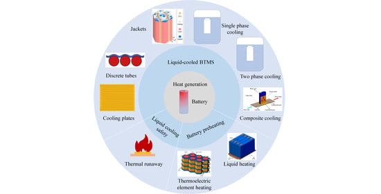
3. Liquid-Cooled BTMS
Liquid cooling can be divided into indirect cooling and direct cooling (also known as immersion cooling), depending on whether the coolant is in contact with the battery, as shown in Figure 4. Indirect liquid cooling usually involves placing cooling plates [48], discrete tubes [8], or jackets [49] on the surface of the cell. This cooling technique moves the heat produced by the battery to the outside with the flowing coolant, avoiding direct contact between the coolant and the battery [50]. In direct liquid cooling, the coolant is in direct contact with the battery, which requires the use of non-conductive medium fluid as coolant [7]. Direct liquid cooling greatly improves the contact area between the battery and the coolant, thereby obtaining an extremely high heat transfer rate. Direct liquid cooling can be divided into single phase and two phase, according to whether the coolant has phase change. Compared with indirect liquid cooling, direct liquid cooling shows a better cooling effect and can improve the uniformity of temperature distribution. As the battery and coolant are in direct contact, this reduces the need for complex flow path designs and reduces the risk of accidental leakage of coolant, which could cause short circuits in the battery [51]. Although direct liquid cooling is considered to be a better choice for the BTMS in the future, it has not been commonly used in electric vehicle [52]. In this section, the main research progress of indirect liquid cooling and direct liquid cooling is introduced. Secondly, the research of different coolants in each part is summarized and analyzed. Finally, attention is paid to the composite cooling system based on liquid cooling.
3.1. Indirect Liquid Cooling
In indirect liquid cooling, different shapes of batteries are suitable for different cooling devices. Cylindrical batteries usually use discrete tubes or jackets in order to have a larger contact area between the surface and the coolant. For prismatic batteries or pouch batteries, flat cold plates are usually the best choice. The air gap between the cooling plate or tube and the battery will contribute to heat insulation and lower heat transfer efficiency as a result of the coolant and battery not making direct contact with each other. A high-precision cold metal plate, as well as a high-thermal-conductivity grease or epoxy bonding agent, are required to eliminate air gaps, thereby reducing thermal contact resistance [5,9,53,54,55]. In order to improve the heat dissipation of the battery, researchers have conducted many studies on indirect liquid cooling. The selection of coolants, the design of flow channels, and the optimization of system structures have received a lot of attention, and these studies are covered in this section.
3.1.1. Coolant
The viscosity, density, thermal conductivity, specific heat capacity, and flow rate of the coolant are significant variables determining the cooling capacity and heat transfer efficiency in liquid cooling. In order not to increase the pumping power and improve the cooling effect, a coolant with high thermal conductivity and low viscosity is needed. As the most accessible liquid in life, water has been widely used in indirect liquid cooling systems. It has been discovered that using water as a coolant may assure battery temperature consistency and enhance BTMS cooling performance [56,57]. Karimi and Dehghan [58] used air, water, and silicone oil as coolants to study the performance of the BTMS. According to the simulation results, using water as a coolant instead of air or silicone oil can not only use less power, but also keep the temperature within reasonable bounds. In addition, water has higher thermal conductivity and specific heat capacity than air, and lower viscosity than oil, which ensures the heat transfer capacity and helps reduce additional energy consumption. In order to reduce the freezing point of water, so that the BTMS can be used at a lower temperature (below zero), the water/glycol mixture is usually used as the coolant. Adding glycol to water can substantially extend the breadth of application of BTMSs and lower the danger of battery damage caused by increased volume following water condensation. To eliminate short circuit issues brought on by contact with the battery following liquid leakage, the BTMS based on water or water/glycol liquid should strictly avoid direct contact between the coolant and the battery [59].
Recently, nanofluids have attracted the attention and research of scholars due to their excellent thermal conductivity in BTMSs [60,61,62]. The thermal conductivity of the liquid is improved by adding metal particles to the water to make it a nanofluid. The concentration and size of nanoparticles are two important factors affecting the thermal conductivity of nanofluids. Zakaria et al. [63] investigated the effect of Al2O3 nanoparticles with different volume concentrations (0.1, 0.3, and 0.5%) on thermal conductivity in a water/glycol mixture. The results showed that the thermal conductivity increased with the concentration of nanoparticles in the water/glycol mixture. In the water/glycol mixture with a volume ratio of 1:1, the volume concentrations of nanoparticles were 0.1%, 0.3%, and 0.5%, respectively, and the thermal conductivity increased by 2%, 4.2%, and 7.5%, respectively. Maheshwary et al. [64] investigated the effects of TiO2 nanoparticle concentration, size, and shape on the thermal conductivity of nanofluids. Thermal conductivity rises with concentration, according to experimental data. Thermal conductivity can also be improved by altering the shape and particle size, although the concentration influences this property the most. In addition, Teng et al. [65] studied the effect of Al2O3 particle size on nanofluids and found that the enhancement effect of nanofluids on thermal conductivity became larger at higher temperatures, and for small-sized nanoparticles, the effect of temperature rise on the thermal conductivity of nanofluids was more obvious. In other studies [66,67], it was also found that smaller nanoparticles are beneficial to enhance the thermal conductivity of nanofluids.
Tousi et al. [68] studied the thermal management of 18650/21700 LIBs based on AgO nanofluids. It was revealed that the maximum temperature and temperature difference of the battery pack were greatly lowered after adding nanoparticles in water, while the pressure drop in the channel was increased. The findings demonstrate that, even at a high discharge rate of 7C, the maximum temperature and temperature difference of the battery can be kept within 33.5 °C and 0.67 °C at an appropriate flow rate and concentration of the nanofluid. Sarchami et al. [69] designed an indirect liquid cooling system combining a cooling channel and a copper sleeve, using Al2O3 nanofluids with volume fractions of 1% and 2% as coolants. Experiments showed that the maximum temperature and maximum temperature difference of the battery can decrease significantly with the increase of nanoparticle concentration. At a 5C charge–discharge rate, the maximum temperature and maximum temperature difference of the battery pack can be reduced below 305.13 K and 2.01 K, respectively. Guo et al. [70] similarly highlighted that the cooling performance of the BTMS can be achieved with more pressure loss. Additionally, they investigated the effect of nanoparticle shape on cell performance and discovered that brick-shaped nanoparticles could reduce cell capacity loss, while spherical-shaped nanoparticles preferred lower pressure loss. Therefore, it can be seen that the addition of nanoparticles is beneficial to improve the thermal conductivity of the coolant and the temperature uniformity in the battery pack, but nanofluids may have problems with particle deposition and blockage. Meanwhile, as nanoparticles are added and the fluid flow rate increases, this can lead to larger pressure drops and energy consumption in the system, which needs to be taken into account when choosing a nanofluid as a coolant.
Liquid metal is used in BTMSs as another coolant with high thermal conductivity. Yang et al. [71] proposed using liquid metal instead of water as a coolant for BTMS. It was found that the liquid metal cooling system has better cooling performance, which can control the battery pack temperature to a lower and more uniform range, while consuming less pumping power. In addition, liquid metals can be applied to extreme conditions, such as rapid charge–discharge processes and high-temperature environments. Liu et al. [72] also found that liquid metal has better cooling capacity and energy consumption than water. A variable flow velocity strategy (VFVS) BTMS was used in Liu’s study in order to modify the liquid flow rate in response to various circumstances. The results demonstrated that under the three conditions of constant ambient temperature with variable C-rate (CTVC), constant C-rate with variable ambient temperature (CCVT), and variable ambient temperature with variable C-rate (VCVT), the pump power is reduced by 47%, 25.6%, and 47%, respectively, in comparison to the conventional constant flow velocity strategy (CFVS). This shows that the liquid metal used in indirect liquid cooling can display good cooling performance and effectively reduce energy consumption. Therefore, liquid metal can be considered to replace water as a coolant in a high-temperature environment and a high discharge rate, but experiments are lacking to verify the effectiveness of liquid metal for use in BTMSs.
In addition to studying coolants with different thermal conductivities to improve the cooling performance of the BTMS, some scholars have also studied the temperature of the coolant inlet. Panchal et al. [21] designed a microchannel cold plate to cool the prismatic battery and studied the water cooling effect at the three operating temperatures of 5 °C, 15 °C, and 25 °C. It was found that the coolant temperature would affect the cooling performance of the cold plate. Malik et al. [73] studied the performance of the battery pack at different coolant temperatures (10 °C, 20 °C, 30 °C, and 40 °C) based on the cold plate. Experimental results showed that the performance of the battery pack was improved with the increase of the coolant temperature. They found that when the coolant temperature is 30 °C, the maximum and average temperature of the battery pack can be controlled within 25 °C to 40 °C, whether at a low discharge rate or a high discharge rate. In Shang’s study [74], it was discovered that the maximum temperature of the battery module decreased with the decrease of the coolant inlet temperature, but the change of temperature uniformity was not noticeable. Therefore, the temperature of the coolant is also an important factor affecting the performance of the BTMS. Appropriately reducing the inlet temperature of the coolant is beneficial to improve the temperature of the battery.
3.1.2. Flow Channel Optimization Design
In indirect liquid cooling, the coolant needs to pass through specific channels. However, different channel designs can have different effects on the thermal performance and energy consumption of the BTMS, so researchers have carried out many studies on channels. For the geometry of the cold plate channels, typical designs are shown in Figure 5. Huo et al. [75] designed a multichannel parallel cold plate (Figure 5a). The effects of channel number, flow direction, mass flow rate, and ambient temperature on battery temperature were studied by numerical simulation. Jarrett et al. [59] used the CFD method to numerically simulate the serpentine channel cold plate (Figure 5b); determined the optimal design of the objective function of cooling hydraulic drop, temperature uniformity, and average temperature; and studied the influence of boundary condition changes on the performance of the cold plate. For the cold plate channel, its shape is mostly linear along the flow direction, and the resistance will increase when the coolant flows in the pipeline. In this case, Huang et al. [76] used streamlined channels for indirect liquid cooling, as shown in Figure 5c. They found that this channel can effectively reduce the flow resistance of the liquid and improve the temperature distribution of the battery. On the other hand, Deng et al. [77] used a U-shaped serpentine channel cold plate (Figure 5d) to reduce the resistance of liquid flow in the channel.
Based on the typical channel structure, parallel channels and serpentine channels are gradually replaced by channels with a better cooling effect. Monika et al. [78] compared six cold plate designs with the same channel volume, as shown in Figure 6a, which are straight channel, serpentine channel, U-shaped channel, pumpkin-shaped channel, spiral channel, and hexagonal structure channel. Through numerical analysis, it was discovered that, despite having a high pressure drop, the snake channel and hexagonal channel have good cooling properties and can significantly improve the temperature distribution of the battery pack. In contrast, the pumpkin-shaped channel is useful for lowering the pressure drop and pumping power. In another study, comparing the performance of the cold plate of the snake channel with that of the parallel channel, it was also found that the pressure drop of the snake channel was greater than that of the parallel channel [79]. Moreover, Chen et al. [80] studied the cooling performance of the BTMS based on a parallel mini-channel cold plate (PMCP), and designed three different flow channels of PMCP (type I, Z, and U). It was discovered that the cooling performance of PMCP was greatly enhanced by altering the edge width and channel width of the cold plate. Three symmetrical PMCPS are also built in Chen’s study, as seen in Figure 6b. The results showed that the symmetrical cold plate can control the maximum temperature and temperature difference of the battery module within a low range, and is conducive to reducing the energy consumption of the system.
With regard to the geometry of the flow channel, topology optimization (TO) can also be used to effectively improve the heat transfer efficiency of the cold plate and reduce the flow loss [81]. TO enables greater flexibility in optimization on the basis of pre-designed channels, thus improving the cooling performance of the system [82]. Chen et al. [83] designed a cooling plate with a new channel structure by TO, as shown in Figure 7. Numerical analysis showed that compared with the conventional rectangular channel cold plate (RCP) and serpentine channel cold plate (SCP), the topology optimization cold plate (TCP) has a higher heat transfer coefficient. At the same inlet pressure, the maximum temperature, temperature difference, and temperature standard deviation of TCP-RCP are 0.27%, 19.5%, and 24.66% lower, respectively, than those of the rectangular channel cold plate (RCP). Sun et al. [84] and Wang et al. [85] also used the TO method to study the cold plate, and found that TO can effectively improve the cooling efficiency of the BTMS. However, the application and research of TO in BTMSs are still relatively few. Most of the studies still analyze the cooling effect through numerical simulation. To explore the feasibility of the cooling plate by TO, TO should be experimentally verified in future research.
In the study of channel width, Jarrett and Kim [59] studied the influence of channel structure on its performance based on the serpentine channel cold plate and proposed several channel designs (Figure 8). Through a numerical optimization algorithm, it is concluded that the minimum average temperature and pressure drop can be optimized by increasing the channel width to the maximum extent. To optimize the design of uniform temperature, the flow channel with a narrow inlet and wide outlet should be adopted. In addition, Qian et al. [86] used numerical analysis to study the performance of parallel channel cold plates and found that when the channel width increased from 3 mm to 6 mm, the pressure drop of the system decreased by 55%. On the other hand, the distance between channels is also important to improve the performance of the cold plate. Choi et al. [87] used the CFD method to assess the design of the serpentine channel cold plate and found that narrowing the channel spacing near the outlet of the cold plate is beneficial to improve the cooling performance. Based on the above research, appropriately increasing the width of the channel and reducing the spacing between the channels may be an optimal choice to improve the performance of the cold plate.
The application of microchannels to indirect liquid cooling can increase the heat transfer area and thermal conductivity, reducing the average and differential temperatures of the battery and enhancing the efficiency of the thermal management system [86,88]. Lan et al. [89] designed a novel BTMS. Aluminum microchannel tubes were placed on the three surfaces of the prismatic battery, and water flowed in the channel as a coolant. According to the results, the BTMS with microchannels can demonstrate a greater cooling effect and lower the maximum temperature and maximum temperature difference of the battery without causing pressure drop or requiring excessive pumping power. For the study of the internal structure of the microchannel, Lee et al. [90] proposed a heat transfer enhancement scheme, using inclined fins to adjust the flow in the microchannel. This design promotes the redevelopment of the boundary layer and the generation of secondary flow and improves the heat transfer performance. Subsequently, Jin et al. [91] proposed a microchannel ultra-thin liquid cold plate (LCP) with inclined fins. As shown in Figure 9, the heat transfer performance of the traditional straight channel will weaken along the axial direction, and the thickness of the boundary layer will increase, resulting in a higher maximum temperature and larger temperature difference. The design of these inclined fins can initialize the flow boundary layer. The research shows that the cold plate with inclined fins has a better cooling effect than the traditional straight channel cold plate, which can significantly improve the performance of the BTMS.
Obviously, the cooling performance of indirect liquid cooling can be improved by adjusting the structure and configuration of the channel, including the channel geometry, channel width, channel spacing, number of inlets and outlets, microchannels, etc. At present, most of the research focuses on numerical simulation and theoretical analysis. In future research, manufacturing technology and cost need to be considered in order to obtain satisfactory results in practical applications.
3.1.3. Structure Optimization of Liquid Cooling System
The location of the cold plate, the contact area between the cooling structure and the battery, the number of cooling channels, and the coolant flow rate have an important influence on the cooling performance of the system. According to the position of the cold plate, it can be divided into bottom cooling and side cooling. Darcovich et al. [92] examined the cooling effectiveness of the two cold plate locations by putting the cold plate on the side and bottom of the prismatic battery. Because side cooling has more contact areas with the battery than bottom cooling, it has a lower maximal temperature and greater temperature uniformity. Tang et al. [93] designed a multichannel wavy tube for cylindrical battery packs. As shown in Figure 10, the two sides of the wave tube have radians that can be in close contact with the side of the battery. The maximum temperature and maximum temperature difference of the battery pack were studied by changing the wavy contact angle () and mass flow. The wave tube can reduce the uneven temperature in the battery pack and has a good heat dissipation capability at low flow rates, according to simulation and experimental results. Similarly, Zhao et al. [94] also designed a side cooling wave channel for the battery pack. Through simulation, it was discovered that even at a charge–discharge rate of 5C, the wave channel was still practical for the thermal control of the battery.
In addition to studying the location of the cooling device, changing the number of cold plates can also improve the temperature distribution of the battery pack. Qian et al. [86] designed two cooling systems based on different numbers of cold plates. The simulation results showed that the three cold plates helped to improve the temperature distribution. When the coolant flow rate is 1 × 10⁻³ kg/s, the maximum temperature and temperature difference of the battery pack are reduced by 13.3% and 43.3%, respectively. In another study [95], the author designed six different arrangement schemes of cold plates to study the heat dissipation effect of the battery pack. The maximum temperature of the battery pack decreased with the increase of the number of cold plates. When the number of cold plates increased to five, the heat dissipation performance of the system was the best. The author emphasized that when the number of cold plates is the same, placing the cold plates evenly near the intermediate battery is beneficial to reduce the maximum temperature. Therefore, within the allowable range of cost and power, side cold plates should be selected as much as possible, and the number of cold plates should be increased.
A key problem in indirect liquid cooling is that there is an air gap between the battery surface and the cooling structure, resulting in a decrease in cooling efficiency. Therefore, it is crucial to design a suitable contact area to increase the effectiveness of heat transfer. Zhou et al. [96] investigated a liquid cooling system based on the half-helical duct, as shown in Figure 11a. They pointed out that this structure is more efficient due to the small volume of liquid and no stagnation zone. Rao et al. [97] proposed a variable contact surface cylindrical BTMS, as shown in Figure 11b. According to the simulation results, the BTMS with a changeable contact surface helps to increase the battery’s temperature uniformity. Siruvuri et al. [98] designed an s-shaped cooling channel and analyzed the influence of the contact area between the channel and the battery on BTMS. They pointed out that increasing the contact area can improve the cooling effect of the battery. In addition, the contact area with the battery can be controlled by changing the width of the cold plate [74] and the angle between the wave tube and the battery [93,94], thereby improving the cooling performance of the BTMS.
The number of cooling channels and the direction of flow are also two key factors in improving cooling performance. Zhao et al. [99] designed a new liquid cooling system for cylindrical LIBs. A liquid-cooled cylinder (LCC) with microchannels was positioned around the battery, as seen in Figure 12a. Numerical simulations have found that the maximum cell temperature can be controlled to within 40 °C when there are no less than 4 channels and a mass flow rate of 1 × 10⁻³ kg/s. For the flow direction, the reverse flow of some channels has little effect on the maximum temperature and temperature difference of the battery. Qian et al. [86] established a three-dimensional liquid cooling model based on the microchannel cold plate. The results showed that the best cooling effect was obtained when the number of channels was five. They designed four cases for different flow directions (Figure 12b). It is found that the maximum temperature of cases 1 and 3 is almost the same, which is 8% lower than that of cases 2 and 4. Deng [77] similarly found that cooling efficiency continued to improve as the number of channels increased, but after the number of channels exceeded five, the improvement became insignificant after increasing the number of channels further. Deng et al. [95] investigated the effect of liquid flow direction in the cold plate channel on cell temperature and found that changing the flow direction of the liquid facilitated the uniformity of the cell temperature.
Therefore, the number of cold plate channels is not as high as possible, and an optimal number of channels exists. As the number of channels increases, it may lead to an uneven distribution of flow rates within the channels, making the temperature difference between cells increase. The change of flow direction is beneficial to reduce the maximum temperature of the battery, but its improvement on the cooling performance is affected by the coolant flow rate [75].
A lot of research has been conducted on the flow rate of coolant in the channel. By increasing the flow rate of the liquid, it is beneficial to dissipate the heat generated by the battery quickly, but it is the same as choosing the number of channels, and we cannot blindly increase the flow rate to improve the heat distribution of the system. It has been found that when the flow rate is increased to a certain value, a higher flow rate has no significant effect on the cooling effect, but instead increases the additional power of the pump. This phenomenon is called the limited cooling capacity when designing BTMS related to the liquid cooling structure of a specific cold plate [100]. Therefore, many studies have considered the balance between cooling effectiveness and energy consumption to find the optimum flow rate [9,13,75,101]. Pan et al. [102] studied the effects of the number of channels, thickness of the cold plate panel, coolant mass flow rate, and thickness of the cooling tube on the cooling performance of the battery system. Based on an orthogonal test created using these four variables, it was discovered that the thickness of the cooling plate or cooling tube had a minor impact on the battery’s ability to dissipate heat, whereas the number of cooling channels and coolant mass flow rate had a significant impact. Increasing the mass flow rate was an efficient way to improve battery heat dissipation. Jia et al. [103] similarly found that the number of pipes and coolant flow rate were the main factors affecting cell temperature uniformity, while pipe width and pipe height were secondary factors.
Mohammadian et al. [104] proposed an internal cooling system, in which the electrolyte acts as a coolant through the microchannel between the positive and negative electrodes of the battery, as shown in Figure 13a. To evaluate the internal and external cooling techniques used by the BTMS, a two-dimensional and three-dimensional transient thermal analysis of the prismatic battery pack was carried out. The results show that internal cooling systems are superior to external cooling systems, with internal cooling reducing the internal cell temperature more than external cooling for the same pumping power, and significantly reducing the standard deviation of the internal cell temperature field. Although internal cooling helps to increase cooling efficiency and decrease the temperature gradient, it will also add weight to the system and be more expensive to manufacture due to its high manufacturing difficulty. In order to improve the safety of indirect liquid cooling, Basu et al. [16] designed an aluminum wave heat conduction element based on the liquid cooling system to replace the contact between the cooling channel and the battery (Figure 13b). The aluminum heat dissipation element transfers the heat generated by the battery to the cooling channels on both sides, and the coolant takes the heat away through the channels on both sides. In the event of coolant leakage, the heat conduction element can be used as a baffle between the coolant and the battery, thereby improving the safety of the BTMS.
Recently, many innovative structures have been proposed in the design of battery packs for electric vehicles (Figure 14) to improve the energy density and volume utilization of the battery system. Conventional battery packs (Figure 14a) are composed of cells, modules, and battery packs, and this method not only results in a waste of space and weight, but also leads to the group efficiency being only about 50%, which limits the driving range [105]. The cell-to-pack (CTP) battery system (Figure 14b,c) skips the module and goes directly from cell to pack, which improves both energy density and volume utilization by 15–20% [106]. However, while the battery system is still a separate structure for CTP, the cell-to-chassis (CTC) battery system (Figure 14d) integrates the battery directly into the vehicle chassis, which not only improves the energy density, but also enables a further increase in space utilization [107]. Compared with conventional battery packs, both CTP and CTC technologies simplify the system structure to increase the energy density of the battery, but from the safety point of view, the batteries are placed closely together, which is easy to cause heat accumulation, thus causing thermal safety problems [108].
The heat dissipation of batteries in CTP and CTC systems mainly relies on cold plates, which brings new challenges to the BTMS. For example, Shen et al. [105] developed a 3D model of the CTP battery system and investigated the heat dissipation performance of the cold plate at the bottom of the battery pack. The simulation results showed that under extreme conditions (4C charging), the maximum temperature of the battery reached 79 °C, implying that the cold plate was not able to meet the heat dissipation needs of the system, and the battery might experience thermal runaway. In order to solve the heat dissipation problem in the CTP battery system, Sun et al. [110] optimized the structure of indirect liquid cooling under fast charging to study the effects of channel height, channel width, coolant flow, and coolant temperature on the battery temperature. The simulation results found that the coolant flow rate and temperature are the main factors affecting the battery temperature, while the channel height and width have little influence, and the temperature of the battery pack can be controlled at 30–35 °C under an effective configuration. In addition, the authors proposed a coolant inlet direction exchange method to reduce the temperature difference of the battery system, and achieved good results. From the perspective of crashworthiness and heat dissipation, Wang et al. [111] added negative Poisson’s ratio (NPR) tubular structures (including an anti-collision layer and heat dissipation layer) on both sides of the CTP battery pack. The numerical simulation results indicated that the CTP-NPR system has superior structural safety and heat dissipation compared with the CTP system. Besides studying the cooling system structure, the safety of BTMS can be improved by optimizing the arrangement structure of batteries. In this regard, Jin et al. [109] investigated the influence of the battery arrangement structure on thermal runaway propagation in CTC systems. The results indicated that the safety of the battery system can be improved by adjusting the battery structure. After changing the battery arrangement from the conventional in-line configuration into the brick configuration, the thermal runaway propagation can be effectively prevented due to the lower peak heat flow in the brick configuration and the fact that the heat can be transferred to more adjacent batteries.
In summary, the performance of battery thermal management can be improved by adjusting the structure of indirect liquid cooling, but as the energy density of the battery continues to increase, this will create higher heat dissipation requirements for BTMS.
3.2. Direct Liquid Cooling
In the direct liquid cooling system, the coolant and the battery are in direct contact, which makes the heat transfer process more effective and simplifies the structure of the system and reduces the contact thermal resistance. The coolant in direct liquid cooling systems should be well-insulated, non-flammable, and environmentally friendly. Commonly used fluids include silicone oil, transformer oil, hydrofluoroether ether, etc. Compared with indirect liquid cooling, it can save space and costs and reduce overall weight, but from the perspective of energy consumption, direct liquid cooling systems require more energy since the coolant has a high viscosity [2]. Several investigators [91,112] have noted that direct liquid cooling systems for BTMSs may not be appropriate for application because of their greater viscosity, which uses more energy than indirect liquid cooling. However, oil-immersed direct contact is a mature transformer cooling technology, which can provide some references for the design of the BTMS [15]. Karimi et al. [58] pointed out that although silicone oil needs high pumping power, it can provide effective cooling performance with an appropriate flow configuration. In addition, Patil et al. [5] showed that dielectric fluid immersion cooling technology is safe, because the voltage and current of LIBs are not affected by immersion cooling and can provide similar electrical properties. Liu et al. [52] suggest that immersion cooling may be a better option for future battery thermal management. In summary, the battery thermal management based on direct liquid cooling has great research significance. The research on direct cooling is introduced below.
3.2.1. Coolant
A typical coolant used for direct cooling is oil. Oil has higher thermal conductivity and electrical insulation than air and water. The temperature of the battery can be reasonably controlled by completely submerging it in oil. Single-phase oils that are frequently used in direct liquid cooling are silicone oil and mineral oil. They have some benefits over conventional coolants, including high dielectric strength, great thermal conductivity, good fire resistance, low corrosion resistance, and difficulty in burning [113]. Chen et al. [9] compared air cooling, direct liquid cooling, and indirect liquid cooling using mineral oil as the coolant in direct contact with the cell and found mineral oil cooling to be more effective than air cooling. However, under the same temperature rise conditions, mineral oil requires a greater flow rate and consumes more energy than indirect cooling with water due to its high viscosity. Similar conclusions were reached by Karimi et al. [58] for a silicone oil study. In order to balance the cooling effect and energy consumption, Liu et al. [101] designed a BTMS based on mineral oil immersion to investigate the improvement of heat dissipation performance with different flow rates. At a 2C discharge rate, it was found that the battery immersed in mineral oil exhibited a better temperature distribution, even when the cooling medium was not flowing, with maximum and maximum temperature differences of 37.35 °C and 2.64 °C for the battery, respectively. As seen in Figure 15, increasing the flow rate of mineral oil reduced the cell temperature and kept the maximum temperature within 35 °C, but the improvement in cooling performance diminished at flow rates above 15 mL/min. Therefore, when using insulating oil as a coolant, as with indirect liquid cooling, there may be a cooling limit. Once the flow rate has increased to a certain value, any further increase in the flow rate will have a more limited improvement in the cooling effect, which requires a balance of energy consumption and cooling effect to be considered in order to select the optimum coolant flow rate.
The BTMS based on boiling heat transfer has attracted attention because of its ability to effectively control the temperature of the battery pack and maintain a uniform battery temperature. Commonly used in the boiling cooling of batteries is the Novec 7000 from 3M in St. Paul, MN, USA, which is non-flammable and has a boiling point of 34 °C, just within the optimum operating temperature range for LIBs [51]. When the temperature is below the boiling point, boiling liquid cooling is a single-phase cooling method that has a much greater cooling capacity than air and can improve the heat distribution of the cell even if boiling does not occur. Once the temperature exceeds the boiling point, the liquid will absorb a large amount of latent heat during evaporation into the gaseous state, keeping the temperature around the boiling point (Figure 16). However, once the liquid has evaporated into a gaseous state, an additional condensation system is required to collect the boiling liquid for recycling, which adds to the complexity of the BTMS. Wu et al. [114] proposed a boiling cooling BTMS, in which Novec 7000 is used as a coolant in direct contact with a 20 Ah LiFePO4 LIB. The surface temperature of the battery can still be kept within 36 °C when the coolant is not flowing, and the temperature uniformity of the battery is also significantly enhanced. The authors proposed an intermittent flow mode, in which the maximum temperature and maximum temperature difference of the cell are controlled to below 36 °C and 2 °C, respectively. Wang et al. [115] and Gils et al. [116] studied Novec 7000 as a coolant in direct contact with the battery, and also obtained a satisfactory cooling effect.
Esters, as another coolant that can be used in direct liquid cooling systems, can be divided into natural esters and synthetic esters. Natural esters are produced by vegetable oils containing a glycerol backbone, while synthetic esters are produced by the reaction between polyol and carboxylic acids [53]. Compared with synthetic esters, natural esters have the disadvantage of being prone to oxidation and requiring the addition of antioxidants. Esters are less harmful to the environment than mineral oils and silicone fluids, lower the risk of pollution even in the case of a leak, have high thermal conductivity, and are non-corrosive. Esters have a greater flash point and ignition point than mineral oils and a higher safety profile than oils, but they also have a higher viscosity, and more studies and evaluations are currently looking into using esters as transformer oils [117,118]. Madavan et al. [119] studied the performance of mixed esters, mixing several natural esters with mineral oils in proportion, and found that the breakdown voltage of the natural ester oils was superior to that of the mineral oils, but the viscosity and acidity of both the natural esters and the mixed oils were higher than that of the mineral oils. The authors noted that the higher-molecular acids are not harmful to the insulation system, but the high viscosity increases energy consumption. Another advantage of esters compared with mineral oil is their renewability. Due to the limited reserves of mineral oil, the feasibility of esters for thermal management systems has received a lot of attention and research. Moreover, the researchers also conducted a study to verify the feasibility of reusing the treated waste vegetable oil. In this regard, Chairul et al. [120] combined several treatments and were able to reduce the acidity of used edible vegetable oils to less than 0.06 mg KOH/g, and the density, viscosity, and electrical properties of the treated oils met the requirements of BS EN 62770.
In the area of BTMSs, M&I has introduced an ester-based immersion cooling medium fluid called MIVOLT with a high ignition point and easy biodegradability, including two products (DF7 for low viscosity and DFK for high viscosity) specifically for use in cooling electric vehicle batteries [53]. Qubeissi et al. [121] proposed a biodiesel-based immersion cooling system using four biodiesels (palm, karanja, jatropha, and mahua oils) in comparison to two conventional coolants (air and 3M Novec). The simulation results showed that using biodiesel for the BTMS was feasible because it could keep the battery pack temperature within a reasonable range. As seen in Figure 17, the cooling effect of palm oil and Novec is essentially the same. Moreover, because palm oil has a lower density than Novec, it facilitates a reduction in total weight. In conclusion, esters have been employed in transformers, but research on BTMSs is still lacking. Esters would be a good candidate coolant for BTMS if a low-viscosity and less oxidizable ester could be discovered as a cooling medium for immersion cooling.
3.2.2. Research on Cooling Performance
In recent years, research on immersion cooling has focused on the cooling effect of single batteries and battery packs. Pulugundla et al. [122] used experimental and numerical analysis to compare the cooling effects of immersion cooling and indirect liquid cooling on single cylindrical cells. They discovered that the cell temperature and temperature gradient of the immersion cooling system was much lower than those of the indirect cooling system at a 3C discharge rate. The authors also pointed out that immersion cooling can offer superior cooling performance for applications involving cylindrical LIBs. According to Bhattacharjee et al. [123], liquid cooling outperformed air cooling. The maximum temperature of the battery pack was decreased by 30.62% by air cooling and by 38.40% by indirect liquid cooling. The immersion cooling system exhibited remarkable cooling capacity, as it can reduce the battery pack’s maximum temperature of 49.76 °C by 44.87% at a 2C discharge rate. Cold plate cooling and immersion cooling were compared by Dubey et al. [54], who came to the conclusion that the high thermal conductivity of immersion cooling at high discharge rates was the reason why the battery pack’s maximum temperature and average temperature were significantly lower than those of the cold plate cooling system. Wang et al. [124] proposed immersion cooling with a compact structure and superior cooling performance (Figure 18). Experimental research was conducted on the effects of the immersion amount and flow rate on battery temperature using transformer oil as a coolant. It was found that the best cooling performance was achieved when the battery was fully submerged. Complete immersion displayed good cooling, even when the liquid was not flowing, with maximum temperatures falling from 58.3 °C to 44.9 °C and maximum temperature differences decreasing from 4.97 °C to 1.43 °C when compared with natural convection cooling. In addition, Sundin et al. [125] and Jithin et al. [126] both conducted studies based on single-phase immersion cooling fluids and similarly concluded that immersion cooling was effective in improving the temperature distribution of the batteries.
Based on immersion cooling, Trimbake et al. [127] proposed a jet impingement immersion cooling of a 4-cell battery pack, using mineral oil as the coolant and designing both submerged jet and direct-jet impingement. Experimental results showed that the proposed jet impingement cooling was able to control the temperature difference between cells, as well as within a single cell, to within 1 °C under 2C charging and 3C discharging, respectively, showing excellent temperature uniformity. Liu et al. [128] examined the heat dissipation capabilities of mineral oil with silicone oil. Figure 19 shows that both insulating oils are able to control the maximum temperature and maximum temperature difference of the cell to within 35 °C and 5 °C, respectively, with the mineral oil providing better cooling than the silicone oil. Moreover, the coolant flow path in immersion cooling has garnered interest. Patil et al. [5] pointed out that the placement of a baffle in direct liquid cooling can alter the flow path of coolant. Compared with no baffle, the maximum temperature and maximum temperature difference of a single battery are decreased by 2.2% and 1.0%, respectively. Han et al. [129] stated that designing an optimal coolant flow path is necessary to improve the cooling effect on the battery thermal management performance and apply it to higher heat dissipation requirements.
In the study of a two-phase immersion cooling system, Al Zareer et al. [130] used the phase change fluid R134a to partially immerse the battery pack in the liquid. The phase change fluid absorbed the heat generated by the battery and evaporated, and the vapor was returned to the cooling system through the condensation channel. Although this cooling method is quite simple, the BTMS based on phase change fluid shows superior cooling performance. It was found that at a 5C charge–discharge rate and a battery coverage of only 40%, the maximum temperature of the battery pack could be kept within 30 °C. To use liquid evaporation to cool the battery pack, the authors also suggested partially immersing the battery in pressurized, saturated liquid ammonia and propane. They discovered that the proposed two-phase immersion cooling system was capable of controlling the battery’s temperature within the ideal temperature range [131,132]. To analyze the cooling effects of indirect cooling, single-phase immersion cooling, and two-phase immersion cooling on the battery pack, Li et al. [133] simulated a system consisting of 18 LiFePO4 pouch cells. The results showed that neither indirect cooling nor single-phase immersion cooling could control the temperature of the battery pack to an acceptable range at a discharge rate of 10C, while in the two-phase immersion cooling system, not only did the maximum temperature go below 35 °C, but it also ensured better temperature uniformity. Recently, Li et al. [134] compared the cooling performance of hydrofluoroolefin (SF33) immersion cooling and forced air cooling, and studied four different depths of discharge (DOD) at different discharge rates. The experimental results showed that the maximum temperature rise of a single cell under forced air cooling was 14.06 °C at a 4C discharge rate, while the maximum temperature rise in immersion cooling was only 4.97 °C. At the same time, they found that even at a 7C discharge rate (Figure 20), the two-phase immersion cooling system was able to control the cell temperature to within 34.5 °C. This is due to the higher discharge rate, which facilitates stronger boiling heat transfer and obtains a stronger heat dissipation capability.
Compared with air cooling, immersion cooling will increase the overall weight, and there is a risk of leaking coolant. Compared with indirect liquid cooling, the viscosity of the coolant is generally higher than that of water, and the optimal flow rate needs to be considered to reduce the additional power of the pump. Therefore, when evaluating the cooling performance of a cooling system, the overall energy consumption should be taken into account, in addition to the cooling effect. Karimi and Li [135] pointed out that the heat transfer rate of silicone oil is much higher than that of air at the same flow rate. At low flow rates, due to the higher viscosity of silicone oil, a higher pumping power is required, which is only 1.5 to 3 times higher than the thermal conductivity of air. Deng et al. [51] discussed the heat transfer efficiency of a high-viscosity submerged cooling oil compared with air at the same pressure drop and found that improvements could only be made to a limited extent. In another study [9] comparing flow rates, pressure drops, and energy consumption for different cooling methods at the same temperature rise, it was found that mineral oil-based immersion cooling was far more efficient than air-cooled systems in balancing pressure drop and heat transfer efficiency, even though a lower flow rate was chosen. Matsuoka et al. [136] studied five immersion cooling media: fluoride FC3283, fluoride FC43, 50cSt silicone oil, 20cSt silicone oil, and soybean oil. They found that the cooling performance in natural convection was influenced by the viscosity of the coolant, with lower-viscosity coolants being able to reduce temperatures significantly. Therefore, 20cSt silicone oil showed superior cooling performance in natural convection than 50cSt silicone oil. Dubey et al. [54] used hydrofluoroether for immersion cooling, which resulted in better pressure drop variation for immersion cooling than indirect cooling due to the lower viscosity and density of hydrofluoroether compared with cold plates using water/glycol. As a result, it is essential to try to choose a coolant with low viscosity in submerged cooling, not only to reduce pressure drop and energy consumption, but also to obtain better cooling performance. In addition to pressure drop and viscosity, Wu et al. [137] used silicone oil as a coolant in direct contact with the cell and found that a silicone oil-based submerged cooling system was able to ensure thermal safety issues for the cell and could reduce the volume occupied by the cell system and also improve the cooling efficiency. Chen et al. [9] and Patil et al. [5] also found that the use of direct liquid cooling could make the cooling system lighter and more compact.
According to the aforementioned research, both single-phase and two-phase immersion cooling systems have demonstrated satisfactory results. Immersion cooling has excellent cooling performance in BTMSs. In immersion cooling systems, more contact area is gained due to the direct contact between the cell and the cooling liquid, which facilitates the compactness of the cell thermal management and the design requirements for high heat transfer efficiency. The flow path of the coolant is worthy of investigation, which is mainly focused on simulations and lacks relevant experimental studies. At the same time, systems based on two-phase immersion cooling fluids have shown superior cooling performance and can be used for cooling under some extreme conditions.
3.3. Composite Cooling
With the rapid advancement of electric cars comes an increase in the demand for battery thermal management. Table 1 lists the benefits and drawbacks of each cooling technique. With high charge–discharge rates and high range requirements, it is difficult to achieve satisfactory results with a single cooling method, and combining two or more types of combined cooling has attracted the attention of researchers. In order to meet the need for high heat dissipation in battery systems under extreme conditions, a composite cooling system based on liquid cooling is discussed in this section.
Air cooling is simple in structure and can be achieved through the cell slits without the need for additional air ducts. The combination with liquid cooling increases the efficiency of thermal management and does not add additional complexity to the cell module structure. To investigate the impact of various assembly structures, air circulation, and liquid cooling conditions on the cell temperature, Wang et al. [139] suggested a composite cooling with a combination of forced air cooling and liquid cooling plates in an enclosed space (Figure 21). According to the research, a structure with a fan mounted beneath the cooling plate was the best option in terms of cooling effectiveness and cost. At a total heat generation of 576 W, the maximum temperature and temperature difference were decreased by 3.45 K and 3.88 K, respectively, and the temperature uniformity and temperature control efficiency were increased by 2.42 and 2.61 times, respectively, compared with the vacuum package’s single cold plate cooling method. They also stated that this composite cooling system has a simple structure with good thermal performance, which can improve the performance and reliability of the battery module in the enclosed space. Yang et al. [140] combined air cooling and microchannel liquid cooling to investigate the thermal performance of a composite cooling system and found that the system facilitated improved battery performance and temperature uniformity. Li et al. [141] similarly found that a combination of air cooling and indirect liquid cooling could improve the performance of the BTMS. Simulations found that under extreme conditions (high temperature and high discharge rate), the maximum cell temperature could be controlled to within 45 °C, but the maximum temperature difference exceeded 5 °C. Traditional active air and liquid cooling works by using additional energy to circulate the cooling medium in order to produce a greater cooling effect, but this cooling effect may not always be as effective as desired.
The thermal management system coupled with liquid cooling and PCM can combine the advantages of the large convective heat transfer coefficient of liquid, large latent heat of PCM, and no energy consumption. It can not only reduce the energy consumption of the system, but also achieve a better cooling effect, and has a good development prospect. The PCM’s moldable shape makes it ideal for embedding cooling channels or cooling plates for quick heat dissipation. Zheng et al. [142] developed a composite cooling system with PCM filling the cooling pipes and battery gaps, and, through simulation, found that it is difficult for PCM to utilize latent heat if the system is primarily liquid-cooled. They mentioned that PCM can be substituted with some high-thermal-conductivity materials because the system can still perform well at cooling, even in the absence of phase shift. In order to take advantage of the latent heat of PCM, Kong et al. [143] proposed a composite cooling system, in which PCM cooling is the mainstay, and liquid cooling is used to recover the latent heat of PCM. The efficacy and practicality of the composite system were confirmed through experiments. Zadeh et al. [144] investigated the BTMS of a 12-cell 18650 LIB pack and designed natural convection cooling, forced convection cooling, finned-natural convection cooling, PCM cooling, and combined cooling with PCM and liquid cooling. According to simulation findings, PCM in conjunction with liquid cooling is the only way to achieve the battery life requirements (≤45 °C). For a battery pack with 40 cylindrical cells, Cao et al. [145] suggested a delayed cooling device using PCM and a cooling plate combination. According to the simulation results, the delayed cooling system can improve the temperature difference between cells, while also reducing the power consumption of the system. The combined cooling can keep the temperature within 55 °C at a 4C discharge rate.
Heat pipes are a highly efficient heat transfer element based on gas–liquid phase change, with a high thermal conductivity that is tens or even hundreds of times higher than that of metals of the same size [146]. The heat pipe uses no extra power, similar to PCM. The evaporation end and the condensation end are the two extremities of the heat pipe, respectively. The evaporation end is in contact with the external heat source. As heat is absorbed by the coolant in the tube core, it will vaporize and travel to the condensation end, and then undergo exothermic liquefaction. Finally, through the capillary force, the cooled liquid travels to the evaporation end. In the BTMS, the condensing end of the heat pipe, which relies only on natural convection to cool it, is unable to meet the heat dissipation requirements of the battery [147]. The combination of heat pipes and liquid cooling to create a BTMS has garnered interest in order to achieve superior cooling. Mei et al. [148] studied the BTMS with heat pipe coupling liquid cooling. The simulation results showed that the liquid cooling thermal management based on the flat heat pipe can effectively improve the temperature uniformity of the battery. Yuan et al. [146] proposed a BTMS coupled with a heat pipe and a cold plate. The condensation end of the heat pipe is in contact with the cooling plate (Figure 22). The coolant flow rate, ambient and inlet coolant temperature, and discharge rate were studied. The experimental results showed that the structure can meet the heat dissipation requirements at a 2C discharge rate in the environment of 30 °C. The maximum temperature and temperature difference of the battery are maintained at 34.1 °C and 1 °C, respectively. Compared with single cooling, composite cooling can meet the heat dissipation requirements of batteries in continuous cycle operation. Liang et al. [149] designed a composite cooling system with the condensing end of the heat pipe embedded in a liquid cooling channel to study the thermal performance of intermittent and continuous cooling, and the results showed that the use of intermittent cooling not only met the thermal requirements of the battery, but also reduced the energy consumption of the system by reducing the operating time. In order to improve the temperature uniformity of the battery module, Wei et al. [150] proposed a reciprocating cooling strategy based on heat pipe-coupled liquid cooling. The simulation found that reciprocating cooling can significantly improve the temperature gradient in the battery module. In summary, the condensing end of the heat pipe can not only be coupled to the cold plate, but can also be submerged directly in the coolant. Although the combination of liquid cooling and heat pipes results in superior cooling, the coolant requires a special container, which increases the complexity of the construction and the weight of the system.
4. Battery Preheating Technology
The BTMS has three functions: preheating the battery at low temperatures, cooling the battery at high temperatures, and controlling the temperature difference between batteries, so that the battery system can maintain stable performance under different conditions. The current research on BTMS mainly focuses on cooling the battery and reducing the temperature difference between batteries, because the high temperature effect of the battery is not limited by the ambient temperature. The high temperature effect is mainly caused by the internal heat generation of LIBs, which usually occurs under fast charging and discharging, while the low temperature effect occurs at lower ambient temperatures [151]. It is worth noting that preheating the battery in cold environments is also an important function of the BTMS, and the heating and cooling will affect each other, so the design of the preheating function in the BTMS should not be neglected.
Battery preheating methods can be divided into internal heating and external heating. Internal heating includes self-heating and current excitation heating, while external heating includes techniques combined with cooling methods and thermoelectric element heating [152]. Although internal heating has higher heating efficiency and better temperature uniformity, the control mechanism of this method is more complicated and may lead to safety problems [153]. External heating is the more common heating method at low temperatures due to its simple construction. Combined with the above research on indirect liquid cooling and direct liquid cooling, this section focuses on the relevant literature based on liquid preheating.
The preheating system can be divided into non-contact heating and immersion heating, according to whether the battery is in contact with liquid or not [154]. Non-contact heating technology can be used to improve preheating performance by adjusting the structure of the system. For example, Tang et al. [155] designed a novel indirect liquid cooling thermal management system, which consists of a straight microchannel flat tube and heat-conducting blocks, and a three-dimensional transient heat transfer model was used to study the thermal performance of the battery system. It was found that the cooling performance of the system increased with the increase of contact surface angle and inlet liquid flow rate. For the preheating study of the battery system at subzero temperature, they found that a larger gradient angle increment was beneficial to improve the temperature uniformity. Chen et al. [156] proposed a double-direction liquid heating system for the CTC battery system to maintain the normal start-up and energy output of the battery at very low temperature (−40 °C). Numerical results showed that the system was able to heat the battery above 0 °C in a short time without consuming much energy. Wu et al. [157] designed a novel BTMS consisting of a vapor chamber (VC) and a microchannel cold plate (Figure 23a) to realize the cooling and heating of the battery system. Numerical simulations and experimental results showed that the proposed hybrid cooling system was able to control the temperature of the battery system within the optimal operating range. They also heated the battery system at subzero temperature and found that the hybrid system can heat the battery faster and maintain good temperature uniformity compared to the system with a microchannel cold plate.
In addition to using the fluid medium as a heat source to heat the battery at low temperatures, it can also be heated by the external thermoelectric element to investigate the effect of the BTMS on the temperature during the heating process. An et al. [158] designed a honeycomb BTMS (Figure 23b) with a combination of liquid cooling and PCM, which has the double function of heating and cooling, where the heating was achieved by the rubber heating belt. The results showed that this composite cooling system can control the maximum temperature and temperature difference of the battery module within 46.21 °C and 3.5 °C, respectively. And the temperature of the battery module can be increased from −15 °C to 10 °C in 6 min under the effect of heating belts with different power, and the maximum temperature difference can be controlled within 5 °C. In order to improve the temperature uniformity of the battery during the preheating process, Wang et al. [159] proposed an immersion preheating system, in which the battery pack was directly immersed in the coolant. The simulation results showed that the temperature rise rate of the system can be as high as 4.18 °C/min, and the temperature difference between batteries can be controlled within 4 °C, showing excellent preheating performance.
Compared with non-contact heating, the immersion preheating method can obtain higher heat transfer coefficient, so as to obtain better temperature rise rate and temperature uniformity [160]. However, considering the space constraints in vehicles, most liquid preheating methods are non-contact. For the liquid preheating system, there are not only the problems of high system tightness requirement and complex structure, but also the balance between energy consumption and heating performance of the BTMS. In the future research, we should further study various preheating systems, so as to realize the application of the battery system in the whole climate and improve the efficiency of BTMS.
5. Liquid Cooling Safety
The goal of BTMSs is to transfer the heat produced by the battery as quickly and efficiently as possible to prevent heat accumulation that could lead to thermal runaway. Nevertheless, some abuse of the battery (mechanical, electrical, and thermal abuse) can lead to thermal runaway, during which the battery may expand, eject, catch fire, or explode [53]. In recent years, there have been many studies on thermal runaway, including the effect of BTMSs on thermal runaway [161,162]. Compared with other cooling methods, liquid cooling has attracted wide attention because of its high thermal conductivity, which can effectively reduce the temperature and temperature difference of the battery and avoid the occurrence of thermal runaway.
To verify that liquid cooling can improve the safety of the system, Mohammed et al. [163] designed a dual-purpose cold plate for prismatic LIBs. They added pins inside the cold plate to increase the contact area and reduce the pressure drop. Through simulation, it is found that whether it is normal operation or thermal runaway, the cold plate can effectively control the temperature of the battery. By increasing the coolant flow rate, the temperature of the battery with thermal runaway can be reduced to 75 °C. Ke et al. [55] studied the effect of indirect liquid cooling on the thermal runaway propagation of the battery pack. The battery pack is composed of 10 batteries in parallel and placed in an indirect liquid cooling system based on a serpentine channel. A section is heated to cause thermal runaway, and the effect of indirect liquid cooling on thermal runaway propagation at different flow rates (0 L/h, 32 L/h, 64 L/h, and 96 L/h) is analyzed. The experimental results showed that the thermal management system could prevent the spread of thermal runaway, but the influence of a lower flow rate on thermal runaway was not obvious. Only when the flow rate is 96 L/h can the spread of thermal runaway be effectively suppressed.
In addition, the combination of PCM and liquid cooling can also be used to suppress the propagation of thermal runaway. In this aspect, Zhang et al. [164] proposed a BTMS with a combination of PCM and liquid cooling (Figure 24a). The results show that this hybrid cooling method can fully meet the heat dissipation requirements under extreme conditions and effectively prevent the spread of thermal runaway. However, the PCM with high thermal conductivity may accelerate thermal runaway propagation, which requires a balance between thermal performance during battery operation and thermal runaway propagation. Subsequently, the author proposed a BTMS composed of non-uniform thermal conductivity PCM and auxiliary liquid cooling (Figure 24b). The PCM with different thermal conductivity was filled around the battery. High-thermal-conductivity PCM (HPCM) was used for battery cooling, and low thermal conductivity PCM (LPCM) was used to slow down the propagation of thermal runaway. Finally, indirect liquid cooling transfers the heat absorbed by PCM to the external environment [165]. They pointed out that this hybrid cooling can meet the needs of system heat dissipation without reducing the energy density of the system, and control the thermal runaway in a specific direction and range to reduce the harm of thermal runaway. Indirect liquid cooling can play a role in managing the thermal runaway of the battery to a certain extent and can slow down the rapid spread of thermal runaway in the battery pack. However, conductive fluid is often used in indirect liquid cooling. Once thermal runaway occurs, it may lead to leakage caused by the rupture of a liquid pipeline, causing greater safety problems.
Many of the cooling media used in immersion cooling can act as flame retardants in addition to being non-conductive, which can act as a barrier to increase system safety [54]. Patil et al. [5] proposed a BTMS based on dielectric fluid and tab cooling, which immersed the battery directly in the dielectric fluid to simulate the thermal runaway caused by the internal short circuit caused by the battery. The results show that this cooling method can effectively manage the thermal runaway of the battery pack. In addition to single-phase immersion cooling, immersion cooling based on two-phase liquids also shows excellent management of thermal runaway. Li et al. [166] designed a direct liquid cooling system based on fluorocarbons and studied the ability of five coolants to suppress the thermal runaway of the battery. There was no thermal runaway in the liquid cooling experiment, indicating that the battery immersed in fluorocarbons can effectively prevent or suppress thermal runaway. Additionally, they noted that since the battery and coolant are in constant contact, direct liquid cooling requires good material compatibility in applications. Studies have shown that immersion cooling has a prominent effect on the control of thermal runaway of the battery, especially based on two-phase cooling fluids, which can make full use of the latent heat of evaporation to control the temperature of the battery within a lower range, thus avoiding thermal runaway caused by excessive temperature. Although immersion cooling has these advantages, there are few studies on the effect of immersion cooling on thermal runaway, mainly focusing on some thermal runaway caused by mechanical abuse and thermal abuse, while electrical abuse has not been studied.
6. Future Developments of Liquid Cooling System
Compared with other cooling, liquid cooling is a promising cooling method. Through the summary and analysis of the above literature, the future development trends of liquid cooling are summarized, and the key problems to be solved are put forward.
As the most easily accessible medium, water has a wide range of applications in indirect liquid cooling. Although the addition of glycol can expand the applicable temperature range of the BTMS, it is difficult to meet the heat dissipation requirements of the battery under fast charging conditions. Nanoparticles and liquid metals can significantly improve thermal conductivity and become ideal candidate materials for BTMSs. Compared with water cooling systems, BTMSs based on nanofluid and liquid metal are able to keep the battery temperature in a much lower range and show excellent cooling performance under extreme conditions. However, the density of the coolant will increase with the addition of nanoparticles, resulting in a larger pressure drop when the liquid flows, which also puts forward higher requirements for the performance of the pump. A key issue for the nanofluid is the preparation of a stable fluid that avoids the occurrence of particle settling and clogging. In order to improve the cooling efficiency by using nanofluids in the future liquid cooling systems, this problem needs to be solved.
Compared with indirect liquid cooling, the single-phase oil immersion cooling system is really a more efficient way. Currently, a major problem in the single-phase oil immersion cooling system is the large energy consumption, which is due to the relatively high viscosity of the oil. At the same flow rate, it will consume more pumping power, resulting in increased energy consumption [43]. There is a limitation of cooling capacity in oil-immersed cooling systems, and energy consumption can be reduced by selecting the appropriate flow rate, but it is not easy to choose the best flow rate for different working conditions and systems. Two-phase immersion cooling is a very effective cooling method. It shows superior heat absorption capacity in the boiling process. Especially, the battery can reduce the temperature of the battery to an acceptable range under fast charging. However, it should be noted that the boiling liquid is expensive and easy to volatilize, which will increase the structural complexity of the entire system and limit its application in electric vehicles [126]. As the driving range and output of electric vehicles increase, a more efficient thermal management system is needed. If these problems can be solved, immersion cooling based on boiling liquid will be a preferred cooling method for high-energy-density batteries.
Electric vehicles should not only consider the cooling performance of the BTMS, but also control the overall cost. For the liquid cooling, the number of channels and the coolant flow rate play a major role in the cooling performance. A higher flow rate is beneficial to achieve a better temperature distribution of the battery, but this will increase the energy consumption and operating cost of the system. For the cold plate design, the complexity of the system will become larger as the number of channels increases, which will not only make it more difficult to manufacture the system, but also discourage maintenance. In the future thermal management system, the system coupled with liquid cooling and PCM seems to be a better way, because PCM does not need additional energy consumption, and the liquid cooling system can cool the PCM to avoid the PCM completely melting and failing. With the addition of PCM, the problem of uneven temperature distribution in liquid cooling systems can be improved, and the energy consumption of the system can also be reduced [167]. The system combining PCM and liquid cooling also offers the advantages of compactness, longer service life, and lower maintenance cost [168]. In addition, this composite thermal management system demonstrates good preheating performance at low temperatures. However, it is worth noting that the composite cooling system of immersion cooling and PCM has not been studied at present, which may be due to the high sealing requirement of the system and the volume change of PCM. In summary, the composite system of liquid cooling combined with PCM is a BTMS with low energy consumption and a good cooling effect.
The preheating function of the system should also be considered in the future liquid cooling research. In the study of battery preheating, although liquid preheating technology has been applied in electric vehicles, it is still a challenge to preheat batteries efficiently and safely. For the external heating technology, the heating method and heat transfer path should be considered, and the parameters can be continuously optimized through numerical simulation, so as to reduce the heat loss and improve the preheating efficiency of the system.
7. Summary and Prospects
According to the above research, liquid cooling is a very efficient thermal management technique that can control the temperature and temperature difference of the battery within an acceptable range. This paper reviews the literature on direct and indirect liquid cooling for BTMSs. The coolant commonly used in indirect liquid cooling is water or a water/glycol mixture, and has been commercialized in the field of electric vehicles. However, the cooling effect of water is limited, and the cooling performance and efficiency of BTMSs can be improved by adding nanoparticles. Liquid metal has the advantages of low viscosity and good thermal conductivity, which can replace water to meet the heat dissipation requirements under some extreme conditions. In addition, the cooling performance of BTMSs can be improved by changing the flow channel design and system structure, but the pressure drop, weight, and cost of the system need to be paid attention to.
The single-phase oil has been used more frequently for direct liquid cooling. However, when increasing the flow rate, care should be taken to balance the cooling effect and energy consumption. The two-phase immersion cooling liquid exhibits an excellent cooling effect, and the boiling point of the liquid can be reduced by changing the pressure, thereby increasing the cooling efficiency of the system. Based on this review, some research weaknesses in direct liquid cooling have been identified. Esters have been applied in transformers, but there is no in-depth study in battery thermal management. Therefore, the feasibility of esters as coolants for direct liquid cooling can be explored, as well as esters that can replace transformer oil. On the other hand, the contact time between the battery and the coolant in direct liquid cooling is long, and material compatibility between the two needs to be considered. At the same time, few articles have studied the effect of immersion cooling on battery performance and thermal runaway.
The composite system of liquid cooling combined with other cooling methods can meet thermal management requirements under different conditions, especially in fast-charging or high-temperature environments. In the development of electric vehicles, the compactness and lightweightness of the battery system have always been concerned. However, liquid cooling brings additional integration challenges that need to be carefully considered when designing a BTMS. In summary, although liquid cooling still has these research gaps and challenges, it is still a promising BTMS.
Author Contributions
Conceptualization, J.L. and Y.J.; methodology, J.L.; software, H.C.; validation, H.C., S.H. and J.L.; formal analysis, H.C. and S.H.; investigation, J.L.; resources, J.L.; data curation, H.C.; writing—original draft preparation, H.C. and M.C.; writing—review and editing, J.L.; visualization, H.C.; supervision, J.L. and M.C.; project administration, Y.J.; funding acquisition, J.L. All authors have read and agreed to the published version of the manuscript.
Funding
This research was funded by the National Natural Science Foundation of China, grant number 51909152.
Data Availability Statement
Data will be available on request.
Conflicts of Interest
The authors declare no conflict of interest.
References
- Zhao, C.; Zhang, B.; Zheng, Y.; Huang, S.; Yan, T.; Liu, X. Hybrid Battery Thermal Management System in Electrical Vehicles: A Review. Energies 2020, 13, 6257. [Google Scholar] [CrossRef]
- Liu, H.; Wei, Z.; He, W.; Zhao, J. Thermal issues about Li-ion batteries and recent progress in battery thermal management systems: A review. Energy Convers. Manag. 2017, 150, 304–330. [Google Scholar] [CrossRef]
- Ouyang, D.; Weng, J.; Chen, M.; Wang, J. Impact of high-temperature environment on the optimal cycle rate of lithium-ion battery. J. Energy Storage 2020, 28, 101242. [Google Scholar] [CrossRef]
- Zhao, R.; Liu, J.; Gu, J.; Zhai, L.; Ma, F. Experimental study of a direct evaporative cooling approach for Li-ion battery thermal management. Int. J. Energy Res. 2020, 44, 6660–6673. [Google Scholar] [CrossRef]
- Suresh Patil, M.; Seo, J.-H.; Lee, M.-Y. A novel dielectric fluid immersion cooling technology for Li-ion battery thermal management. Energy Convers. Manag. 2021, 229, 113715. [Google Scholar] [CrossRef]
- Bravo Diaz, L.; He, X.; Hu, Z.; Restuccia, F.; Marinescu, M.; Barreras, J.V.; Patel, Y.; Offer, G.; Rein, G. Review—Meta-Review of Fire Safety of Lithium-Ion Batteries: Industry Challenges and Research Contributions. J. Electrochem. Soc. 2020, 167, 090559. [Google Scholar] [CrossRef]
- An, Z.; Jia, L.; Ding, Y.; Dang, C.; Li, X. A review on lithium-ion power battery thermal management technologies and thermal safety. J. Therm. Sci. 2017, 26, 391–412. [Google Scholar] [CrossRef]
- Xia, G.; Cao, L.; Bi, G. A review on battery thermal management in electric vehicle application. J. Power Sources 2017, 367, 90–105. [Google Scholar] [CrossRef]
- Chen, D.; Jiang, J.; Kim, G.-H.; Yang, C.; Pesaran, A. Comparison of different cooling methods for lithium ion battery cells. Appl. Therm. Eng. 2016, 94, 846–854. [Google Scholar] [CrossRef] [Green Version]
- Yan, J.; Li, K.; Chen, H.; Wang, Q.; Sun, J. Experimental study on the application of phase change material in the dynamic cycling of battery pack system. Energy Convers. Manag. 2016, 128, 12–19. [Google Scholar] [CrossRef]
- Ouyang, D.; Chen, M.; Huang, Q.; Weng, J.; Wang, Z.; Wang, J. A Review on the Thermal Hazards of the Lithium-Ion Battery and the Corresponding Countermeasures. Appl. Sci. 2019, 9, 2483. [Google Scholar] [CrossRef] [Green Version]
- Jaguemont, J.; Van Mierlo, J. A comprehensive review of future thermal management systems for battery-electrified vehicles. J. Energy Storage 2020, 31, 101551. [Google Scholar] [CrossRef]
- Wang, H.; Tao, T.; Xu, J.; Mei, X.; Liu, X.; Gou, P. Cooling capacity of a novel modular liquid-cooled battery thermal management system for cylindrical lithium ion batteries. Appl. Therm. Eng. 2020, 178, 115591. [Google Scholar] [CrossRef]
- Qin, P.; Liao, M.; Zhang, D.; Liu, Y.; Sun, J.; Wang, Q. Experimental and numerical study on a novel hybrid battery thermal management system integrated forced-air convection and phase change material. Energy Convers. Manag. 2019, 195, 1371–1381. [Google Scholar] [CrossRef]
- Wu, W.; Wang, S.; Wu, W.; Chen, K.; Hong, S.; Lai, Y. A critical review of battery thermal performance and liquid based battery thermal management. Energy Convers. Manag. 2019, 182, 262–281. [Google Scholar] [CrossRef]
- Basu, S.; Hariharan, K.S.; Kolake, S.M.; Song, T.; Sohn, D.K.; Yeo, T. Coupled electrochemical thermal modelling of a novel Li-ion battery pack thermal management system. Appl. Energy 2016, 181, 1–13. [Google Scholar] [CrossRef]
- Chawla, N.; Bharti, N.; Singh, S. Recent Advances in Non-Flammable Electrolytes for Safer Lithium-Ion Batteries. Batteries 2019, 5, 19. [Google Scholar] [CrossRef] [Green Version]
- Zhu, H.; Qin, X.; Sun, X.; Yan, W.; Yang, J.; Xie, Y. Rocking-chair configuration in ultrathin lithium vanadate-graphene hybrid nanosheets for electrical modulation. Sci. Rep. 2013, 3, 1246. [Google Scholar] [CrossRef] [Green Version]
- Wang, Q.; Mao, B.; Stoliarov, S.I.; Sun, J. A review of lithium ion battery failure mechanisms and fire prevention strategies. Prog. Energy Combust. Sci. 2019, 73, 95–131. [Google Scholar] [CrossRef]
- Li, B.; Xia, D. Anionic Redox in Rechargeable Lithium Batteries. Adv. Mater. 2017, 29, 1701054. [Google Scholar] [CrossRef]
- Panchal, S.; Khasow, R.; Dincer, I.; Agelin-Chaab, M.; Fraser, R.; Fowler, M. Thermal design and simulation of mini-channel cold plate for water cooled large sized prismatic lithium-ion battery. Appl. Therm. Eng. 2017, 122, 80–90. [Google Scholar] [CrossRef]
- Lai, Y.; Du, S.; Ai, L.; Ai, L.; Cheng, Y.; Tang, Y.; Jia, M. Insight into heat generation of lithium ion batteries based on the electrochemical-thermal model at high discharge rates. Int. J. Hydrog. Energy 2015, 40, 13039–13049. [Google Scholar] [CrossRef]
- Zhang, X. Thermal analysis of a cylindrical lithium-ion battery. Electrochim. Acta 2011, 56, 1246–1255. [Google Scholar] [CrossRef]
- Zhao, R.; Gu, J.; Liu, J. An investigation on the significance of reversible heat to the thermal behavior of lithium ion battery through simulations. J. Power Sources 2014, 266, 422–432. [Google Scholar] [CrossRef]
- Christensen, J.; Cook, D.; Albertus, P. An Efficient Parallelizable 3D Thermoelectrochemical Model of a Li-Ion Cell. J. Electrochem. Soc. 2013, 160, A2258–A2267. [Google Scholar] [CrossRef]
- Guo, M.; Sikha, G.; White, R.E. Single-Particle Model for a Lithium-Ion Cell: Thermal Behavior. J. Electrochem. Soc. 2011, 158, A122. [Google Scholar] [CrossRef]
- Bernardi, D.; Pawlikowski, E.; Newman, J. A General Energy Balance for Battery Systems. J. Electrochem. Soc. 2019, 132, 5–12. [Google Scholar] [CrossRef] [Green Version]
- Smith, K.; Wang, C.-Y. Power and thermal characterization of a lithium-ion battery pack for hybrid-electric vehicles. J. Power Sources 2006, 160, 662–673. [Google Scholar] [CrossRef]
- Fathabadi, H. A novel design including cooling media for Lithium-ion batteries pack used in hybrid and electric vehicles. J. Power Sources 2014, 245, 495–500. [Google Scholar] [CrossRef]
- Kalaf, O.; Solyali, D.; Asmael, M.; Zeeshan, Q.; Safaei, B.; Askir, A. Experimental and simulation study of liquid coolant battery thermal management system for electric vehicles: A review. Int. J. Energy Res. 2020, 45, 6495–6517. [Google Scholar] [CrossRef]
- Ping, P.; Wang, Q.; Chung, Y.; Wen, J. Modelling electro-thermal response of lithium-ion batteries from normal to abuse conditions. Appl. Energy 2017, 205, 1327–1344. [Google Scholar] [CrossRef] [Green Version]
- Liebig, G.; Gupta, G.; Kirstein, U.; Schuldt, F.; Agert, C. Parameterization and Validation of an Electrochemical Thermal Model of a Lithium-Ion Battery. Batteries 2019, 5, 62. [Google Scholar] [CrossRef] [Green Version]
- Liebig, G.; Kirstein, U.; Geißendörfer, S.; Schuldt, F.; Agert, C. The Impact of Environmental Factors on the Thermal Characteristic of a Lithium–ion Battery. Batteries 2020, 6, 3. [Google Scholar] [CrossRef] [Green Version]
- Panchal, S.; Mathew, M.; Fraser, R.; Fowler, M. Electrochemical thermal modeling and experimental measurements of 18650 cylindrical lithium-ion battery during discharge cycle for an EV. Appl. Therm. Eng. 2018, 135, 123–132. [Google Scholar] [CrossRef]
- Jaguemont, J.; Boulon, L.; Dubé, Y. A comprehensive review of lithium-ion batteries used in hybrid and electric vehicles at cold temperatures. Appl. Energy 2016, 164, 99–114. [Google Scholar] [CrossRef]
- Wang, Q.; Ping, P.; Zhao, X.; Chu, G.; Sun, J.; Chen, C. Thermal runaway caused fire and explosion of lithium ion battery. J. Power Sources 2012, 208, 210–224. [Google Scholar] [CrossRef]
- Wang, Q.; Jiang, B.; Li, B.; Yan, Y. A critical review of thermal management models and solutions of lithium-ion batteries for the development of pure electric vehicles. Renew. Sustain. Energy Rev. 2016, 64, 106–128. [Google Scholar] [CrossRef]
- Zhang, Y.; Ge, H.; Huang, J.; Li, Z.; Zhang, J. A comparative degradation study of commercial lithium-ion cells under low-temperature cycling. RSC Adv. 2017, 7, 23157–23163. [Google Scholar] [CrossRef] [Green Version]
- Petzl, M.; Kasper, M.; Danzer, M.A. Lithium plating in a commercial lithium-ion battery—A low-temperature aging study. J. Power Sources 2015, 275, 799–807. [Google Scholar] [CrossRef]
- Broussely, M.; Biensan, P.; Bonhomme, F.; Blanchard, P.; Herreyre, S.; Nechev, K.; Staniewicz, R.J. Main aging mechanisms in Li ion batteries. J. Power Sources 2005, 146, 90–96. [Google Scholar] [CrossRef]
- Zhao, R.; Gu, J.; Liu, J. An experimental study of heat pipe thermal management system with wet cooling method for lithium ion batteries. J. Power Sources 2015, 273, 1089–1097. [Google Scholar] [CrossRef]
- Ramadass PH BW RP, B.; Haran, B.; White, R.; Popov, B.N. Capacity fade of Sony 18650 cells cycled at elevated temperatures Part I. Cycling performance. J. Power Sources 2002, 112, 606–613. [Google Scholar] [CrossRef] [Green Version]
- Tan, X.; Lyu, P.; Fan, Y.; Rao, J.; Ouyang, K. Numerical investigation of the direct liquid cooling of a fast-charging lithium-ion battery pack in hydrofluoroether. Appl. Therm. Eng. 2021, 196, 117279. [Google Scholar] [CrossRef]
- Yang, N.; Zhang, X.; Shang, B.; Li, G. Unbalanced discharging and aging due to temperature differences among the cells in a lithium-ion battery pack with parallel combination. J. Power Sources 2016, 306, 733–741. [Google Scholar] [CrossRef]
- Chiu, K.-C.; Lin, C.-H.; Yeh, S.-F.; Lin, Y.-H.; Huang, C.-S.; Chen, K.-C. Cycle life analysis of series connected lithium-ion batteries with temperature difference. J. Power Sources 2014, 263, 75–84. [Google Scholar] [CrossRef]
- Bandhauer, T.M.; Garimella, S.; Fuller, T.F. A Critical Review of Thermal Issues in Lithium-Ion Batteries. J. Electrochem. Soc. 2011, 158, R1. [Google Scholar] [CrossRef]
- Liu, L.; Zhang, X.; Lin, X. Recent Developments of Thermal Management Strategies for Lithium-Ion Batteries: A State-of-The-Art Review. Energy Technol. 2022, 10, 2101135. [Google Scholar] [CrossRef]
- E, J.; Xu, S.; Deng, Y.; Zhu, H.; Zuo, W.; Wang, H.; Chen, J.; Peng, Q.; Zhang, Z. Investigation on thermal performance and pressure loss of the fluid cold-plate used in thermal management system of the battery pack. Appl. Therm. Eng. 2018, 145, 552–568. [Google Scholar] [CrossRef]
- Sheng, L.; Zhang, H.; Su, L.; Zhang, Z.; Zhang, H.; Li, K.; Fang, Y.; Ye, W. Effect analysis on thermal profile management of a cylindrical lithium-ion battery utilizing a cellular liquid cooling jacket. Energy 2021, 220, 119725. [Google Scholar] [CrossRef]
- Thakur, A.K.; Prabakaran, R.; Elkadeem, M.R.; Sharshir, S.W.; Arıcı, M.; Wang, C.; Zhao, W.; Hwang, J.-Y.; Saidur, R. A state of art review and future viewpoint on advance cooling techniques for Lithium–ion battery system of electric vehicles. J. Energy Storage 2020, 32, 101771. [Google Scholar] [CrossRef]
- Deng, Y.; Feng, C.; E, J.; Zhu, H.; Chen, J.; Wen, M.; Yin, H. Effects of different coolants and cooling strategies on the cooling performance of the power lithium ion battery system: A review. Appl. Therm. Eng. 2018, 142, 10–29. [Google Scholar] [CrossRef]
- Liu, J.; Li, H.; Li, W.; Shi, J.; Wang, H.; Chen, J. Thermal characteristics of power battery pack with liquid-based thermal management. Appl. Therm. Eng. 2020, 164, 114421. [Google Scholar] [CrossRef]
- Roe, C.; Feng, X.; White, G.; Li, R.; Wang, H.; Rui, X.; Li, C.; Zhang, F.; Null, V.; Parkes, M.; et al. Immersion cooling for lithium-ion batteries—A review. J. Power Sources 2022, 525, 231094. [Google Scholar] [CrossRef]
- Dubey, P.; Pulugundla, G.; Srouji, A.K. Direct Comparison of Immersion and Cold-Plate Based Cooling for Automotive Li-Ion Battery Modules. Energies 2021, 14, 1259. [Google Scholar] [CrossRef]
- Ke, Q.; Li, X.; Guo, J.; Cao, W.; Wang, Y.; Jiang, F. The retarding effect of liquid-cooling thermal management on thermal runaway propagation in lithium-ion batteries. J. Energy Storage 2022, 48, 104063. [Google Scholar] [CrossRef]
- Wang, C.; Zhang, G.; Li, X.; Huang, J.; Wang, Z.; Lv, Y.; Meng, L.; Situ, W.; Rao, M. Experimental examination of large capacity liFePO4 battery pack at high temperature and rapid discharge using novel liquid cooling strategy. Int. J. Energy Res. 2018, 42, 1172–1182. [Google Scholar] [CrossRef]
- Panchal, S.; Dincer, I.; Agelin-Chaab, M.; Fraser, R.; Fowler, M. Thermal modeling and validation of temperature distributions in a prismatic lithium-ion battery at different discharge rates and varying boundary conditions. Appl. Therm. Eng. 2016, 96, 190–199. [Google Scholar] [CrossRef]
- Karimi, G.; Dehghan, A.R. Thermal analysis of high-power lithium-ion battery packs using flow network approach. Int. J. Energy Res. 2014, 38, 1793–1811. [Google Scholar] [CrossRef]
- Jarrett, A.; Kim, I.Y. Design optimization of electric vehicle battery cooling plates for thermal performance. J. Power Sources 2011, 196, 10359–10368. [Google Scholar] [CrossRef]
- Tran, L.; Lopez, J.; Lopez, J.; Uriostegui, A.; Barrera, A.; Wiggins, N. Li-ion battery cooling system integrates in nano-fluid environment. Appl Nanosci 2017, 7, 25–29. [Google Scholar] [CrossRef]
- Liu, H.; Chika, E.; Zhao, J. Investigation into the effectiveness of nanofluids on the mini-channel thermal management for high power lithium ion battery. Appl. Therm. Eng. 2018, 142, 511–523. [Google Scholar] [CrossRef]
- Wiriyasart, S.; Hommalee, C.; Sirikasemsuk, S.; Prurapark, R.; Naphon, P. Thermal management system with nanofluids for electric vehicle battery cooling modules. Case Stud. Therm. Eng. 2020, 18, 100583. [Google Scholar] [CrossRef]
- Zakaria, I.; Azmi, W.H.; Mohamed, W.A.N.W.; Mamat, R.; Najafi, G. Experimental Investigation of Thermal Conductivity and Electrical Conductivity of Al2O3 Nanofluid in Water—Ethylene Glycol Mixture for Proton Exchange Membrane Fuel Cell Application. Int. Commun. Heat Mass Transf. 2015, 61, 61–68. [Google Scholar] [CrossRef] [Green Version]
- Maheshwary, P.B.; Handa, C.C.; Nemade, K.R. A comprehensive study of effect of concentration, particle size and particle shape on thermal conductivity of titania/water based nanofluid. Appl. Therm. Eng. 2017, 119, 79–88. [Google Scholar] [CrossRef]
- Teng, T.-P.; Hung, Y.-H.; Teng, T.-C.; Mo, H.-E.; Hsu, H.-G. The effect of alumina/water nanofluid particle size on thermal conductivity. Appl. Therm. Eng. 2010, 30, 2213–2218. [Google Scholar] [CrossRef]
- Das, P.K. A review based on the effect and mechanism of thermal conductivity of normal nanofluids and hybrid nanofluids. J. Mol. Liq. 2017, 240, 420–446. [Google Scholar] [CrossRef]
- Wu, J.; Zhao, J.; Lei, J.; Liu, B. Effectiveness of nanofluid on improving the performance of microchannel heat sink. Appl. Therm. Eng. 2016, 101, 402–412. [Google Scholar] [CrossRef]
- Tousi, M.; Sarchami, A.; Kiani, M.; Najafi, M.; Houshfar, E. Numerical study of novel liquid-cooled thermal management system for cylindrical Li-ion battery packs under high discharge rate based on AgO nanofluid and copper sheath. J. Energy Storage 2021, 41, 102910. [Google Scholar] [CrossRef]
- Sarchami, A.; Najafi, M.; Imam, A.; Houshfar, E. Experimental study of thermal management system for cylindrical Li-ion battery pack based on nanofluid cooling and copper sheath. Int. J. Therm. Sci. 2022, 171, 107244. [Google Scholar] [CrossRef]
- Guo, Z.; Wang, Y.; Zhao, S.; Zhao, T.; Ni, M. Investigation of battery thermal management system with considering effect of battery aging and nanofluids. Int. J. Heat Mass Transf. 2023, 202, 123685. [Google Scholar] [CrossRef]
- Yang, X.-H.; Tan, S.-C.; Liu, J. Thermal management of Li-ion battery with liquid metal. Energy Convers. Manag. 2016, 117, 577–585. [Google Scholar] [CrossRef]
- Liu, Z.; Wang, H.; Yang, C.; Zhao, J. Simulation study of lithium-ion battery thermal management system based on a variable flow velocity method with liquid metal. Appl. Therm. Eng. 2020, 179, 115578. [Google Scholar] [CrossRef]
- Malik, M.; Dincer, I.; Rosen, M.A.; Mathew, M.; Fowler, M. Thermal and electrical performance evaluations of series connected Li-ion batteries in a pack with liquid cooling. Appl. Therm. Eng. 2018, 129, 472–481. [Google Scholar] [CrossRef]
- Shang, Z.; Qi, H.; Liu, X.; Ouyang, C.; Wang, Y. Structural optimization of lithium-ion battery for improving thermal performance based on a liquid cooling system. Int. J. Heat Mass Transf. 2019, 130, 33–41. [Google Scholar] [CrossRef]
- Huo, Y.; Rao, Z.; Liu, X.; Zhao, J. Investigation of power battery thermal management by using mini-channel cold plate. Energy Convers. Manag. 2015, 89, 387–395. [Google Scholar] [CrossRef]
- Huang, Y.; Mei, P.; Lu, Y.; Huang, R.; Yu, X.; Chen, Z.; Roskilly, A.P. A novel approach for Lithium-ion battery thermal management with streamline shape mini channel cooling plates. Appl. Therm. Eng. 2019, 157, 113623. [Google Scholar] [CrossRef]
- Deng, T.; Zhang, G.; Ran, Y. Study on thermal management of rectangular Li-ion battery with serpentine-channel cold plate. Int. J. Heat Mass Transf. 2018, 125, 143–152. [Google Scholar] [CrossRef]
- Monika, K.; Datta, S.P. Comparative assessment among several channel designs with constant volume for cooling of pouch-type battery module. Energy Convers. Manag. 2022, 251, 114936. [Google Scholar] [CrossRef]
- Chen, F.C.; Gao, Z.; Loutfy, R.O.; Hecht, M. Analysis of Optimal Heat Transfer in a PEM Fuel Cell Cooling Plate. Fuel Cells 2003, 3, 181–188. [Google Scholar] [CrossRef]
- Chen, K.; Chen, Y.; Song, M.; Wang, S. Multi-parameter structure design of parallel mini-channel cold plate for battery thermal management. Int. J. Energy Res. 2020, 44, 4321–4334. [Google Scholar] [CrossRef]
- Li, H.; Ding, X.; Jing, D.; Xiong, M.; Meng, F. Experimental and numerical investigation of liquid-cooled heat sinks designed by topology optimization. Int. J. Therm. Sci. 2019, 146, 106065. [Google Scholar] [CrossRef]
- Guo, C.; Liu, H.-l.; Guo, Q.; Shao, X.-d.; Zhu, M.-l. Investigations on a novel cold plate achieved by topology optimization for lithium-ion batteries. Energy 2022, 261, 125097. [Google Scholar] [CrossRef]
- Chen, F.; Wang, J.; Yang, X. Topology optimization design and numerical analysis on cold plates for lithium-ion battery thermal management. Int. J. Heat Mass Transf. 2022, 183, 122087. [Google Scholar] [CrossRef]
- Sun, Y.; Bai, R.; Ma, J. Design and thermal analysis of a new topological cooling plate for prismatic lithium battery thermal management. Appl. Therm. Eng. 2023, 219, 119547. [Google Scholar] [CrossRef]
- Wang, Y.; Duong, X.Q.; Zadeh, P.G.; Chung, J.D. Liquid-cooled cold plate for a Li-ion battery thermal management system designed by topology optimization. J. Mech. Sci. Technol. 2023, 37, 2079–2086. [Google Scholar] [CrossRef]
- Qian, Z.; Li, Y.; Rao, Z. Thermal performance of lithium-ion battery thermal management system by using mini-channel cooling. Energy Convers. Manag. 2016, 126, 622–631. [Google Scholar] [CrossRef]
- Choi, J.; Kim, Y.-H.; Lee, Y.; Lee, K.-J.; Kim, Y. Numerical analysis on the performance of cooling plates in a PEFC. J. Mech. Sci. Technol. 2008, 22, 1417–1425. [Google Scholar] [CrossRef]
- Du, X.; Qian, Z.; Chen, Z.; Rao, Z. Experimental investigation on mini-channel cooling-based thermal management for Li-ion battery module under different cooling schemes. Int. J. Energy Res. 2018, 42, 2781–2788. [Google Scholar] [CrossRef]
- Lan, C.; Xu, J.; Qiao, Y.; Ma, Y. Thermal management for high power lithium-ion battery by minichannel aluminum tubes. Appl. Therm. Eng. 2016, 101, 284–292. [Google Scholar] [CrossRef] [Green Version]
- Lee, Y.J.; Lee, P.S.; Chou, S.K. Enhanced Thermal Transport in Microchannel Using Oblique Fins. J. Heat Transf. 2012, 134, 101901. [Google Scholar] [CrossRef]
- Jin, L.W.; Lee, P.S.; Kong, X.X.; Fan, Y.; Chou, S.K. Ultra-thin minichannel LCP for EV battery thermal management. Appl. Energy 2014, 113, 1786–1794. [Google Scholar] [CrossRef]
- Darcovich, K.; MacNeil, D.D.; Recoskie, S.; Cadic, Q.; Ilinca, F. Comparison of cooling plate configurations for automotive battery pack thermal management. Appl. Therm. Eng. 2019, 155, 185–195. [Google Scholar] [CrossRef]
- Tang, Z.; Min, X.; Song, A.; Cheng, J. Thermal Management of a Cylindrical Lithium-Ion Battery Module Using a Multichannel Wavy Tube. J. Energy Eng. 2019, 145, 04018072. [Google Scholar] [CrossRef]
- Zhao, C.; Cao, W.; Dong, T.; Jiang, F. Thermal behavior study of discharging/charging cylindrical lithium-ion battery module cooled by channeled liquid flow. Int. J. Heat Mass Transf. 2018, 120, 751–762. [Google Scholar] [CrossRef]
- Deng, T.; Zhang, G.; Ran, Y.; Liu, P. Thermal performance of lithium ion battery pack by using cold plate. Appl. Therm. Eng. 2019, 160, 114088. [Google Scholar] [CrossRef]
- Zhou, H.; Zhou, F.; Zhang, Q.; Wang, Q.; Song, Z. Thermal management of cylindrical lithium-ion battery based on a liquid cooling method with half-helical duct. Appl. Therm. Eng. 2019, 162, 114257. [Google Scholar] [CrossRef]
- Rao, Z.; Qian, Z.; Kuang, Y.; Li, Y. Thermal performance of liquid cooling based thermal management system for cylindrical lithium-ion battery module with variable contact surface. Appl. Therm. Eng. 2017, 123, 1514–1522. [Google Scholar] [CrossRef]
- Siruvuri, S.D.V.S.S.V.; Budarapu, P.R. Studies on thermal management of Lithium-ion battery pack using water as the cooling fluid. J. Energy Storage 2020, 29, 101377. [Google Scholar] [CrossRef]
- Zhao, J.; Rao, Z.; Li, Y. Thermal performance of mini-channel liquid cooled cylinder based battery thermal management for cylindrical lithium-ion power battery. Energy Convers. Manag. 2015, 103, 157–165. [Google Scholar] [CrossRef]
- Huang, Y.; Wang, S.; Lu, Y.; Huang, R.; Yu, X. Study on a liquid cooled battery thermal management system pertaining to the transient regime. Appl. Therm. Eng. 2020, 180, 115793. [Google Scholar] [CrossRef]
- Liu, J.; Fan, Y.; Xie, Q. Feasibility study of a novel oil-immersed battery cooling system: Experiments and theoretical analysis. Appl. Therm. Eng. 2022, 208, 118251. [Google Scholar] [CrossRef]
- Pan, C.; Tang, Q.; He, Z.; Wang, L.; Chen, L. Structure Optimization of Battery Module With a Parallel Multi-Channel Liquid Cooling Plate Based on Orthogonal Test. J. Electrochem. Energy Convers. Storage 2020, 17, 021104. [Google Scholar] [CrossRef]
- E, J.; Han, D.; Qiu, A.; Zhu, H.; Deng, Y.; Chen, J.; Zhao, X.; Zuo, W.; Wang, H.; Chen, J.; et al. Orthogonal experimental design of liquid-cooling structure on the cooling effect of a liquid-cooled battery thermal management system. Appl. Therm. Eng. 2018, 132, 508–520. [Google Scholar] [CrossRef]
- Mohammadian, S.K.; He, Y.-L.; Zhang, Y. Internal cooling of a lithium-ion battery using electrolyte as coolant through microchannels embedded inside the electrodes. J. Power Sources 2015, 293, 458–466. [Google Scholar] [CrossRef]
- Shen, K.; Sun, J.; Zheng, Y.; Xu, C.; Wang, H.; Wang, S.; Chen, S.; Feng, X. A comprehensive analysis and experimental investigation for the thermal management of cell-to-pack battery system. Appl. Therm. Eng. 2022, 211, 118422. [Google Scholar] [CrossRef]
- Wang, H.; Wang, S.; Feng, X.; Zhang, X.; Dai, K.; Sheng, J.; Zhao, Z.; Du, Z.; Zhang, Z.; Shen, K.; et al. An experimental study on the thermal characteristics of the Cell-To-Pack system. Energy 2021, 227, 120338. [Google Scholar] [CrossRef]
- Fichtner, M. Recent Research and Progress in Batteries for Electric Vehicles. Batter. Supercaps 2021, 5, e202100224. [Google Scholar] [CrossRef]
- Hu, G.; Huang, P.; Bai, Z.; Wang, Q.; Qi, K. Comprehensively analysis the failure evolution and safety evaluation of automotive lithium ion battery. eTransportation 2021, 10, 100140. [Google Scholar] [CrossRef]
- Jin, C.; Sun, Y.; Yao, J.; Feng, X.; Lai, X.; Shen, K.; Wang, H.; Rui, X.; Xu, C.; Zheng, Y.; et al. No thermal runaway propagation optimization design of battery arrangement for cell-to-chassis technology. eTransportation 2022, 14, 100199. [Google Scholar] [CrossRef]
- Sun, J.; Chen, S.; Shen, K.; Zheng, Y. Liquid cooling system optimization for a cell-to-pack battery module under fast charging. Int. J. Energy Res. 2022, 46, 12241–12253. [Google Scholar] [CrossRef]
- Wang, W.; Dai, S.; Zhao, W.; Wang, C.; Ma, T. Design optimization of a novel negative Poisson’s ratio non-module battery pack system considering crashworthiness and heat dissipation. Compos. Struct. 2021, 275, 114458. [Google Scholar] [CrossRef]
- Chen, K.; Li, X. Accurate determination of battery discharge characteristics—A comparison between two battery temperature control methods. J. Power Sources 2014, 247, 961–966. [Google Scholar] [CrossRef]
- Amalesh, T.; Lakshmi Narasimhan, N. Cooling of a lithium ion battery using phase change material with air/dielectric fluid media: A numerical study. Proc. Inst. Mech. Eng. Part A J. Power Energy 2019, 234, 722–738. [Google Scholar] [CrossRef]
- Wu, N.; Ye, X.; Yao, J.; Zhang, X.; Zhou, X.; Yu, B. Efficient thermal management of the large-format pouch lithium-ion cell via the boiling-cooling system operated with intermittent flow. Int. J. Heat Mass Transf. 2021, 170, 121018. [Google Scholar] [CrossRef]
- Wang, Y.-F.; Wu, J.-T. Thermal performance predictions for an HFE-7000 direct flow boiling cooled battery thermal management system for electric vehicles. Energy Convers. Manag. 2020, 207, 112569. [Google Scholar] [CrossRef]
- van Gils, R.W.; Danilov, D.; Notten, P.H.L.; Speetjens, M.F.M.; Nijmeijer, H. Battery thermal management by boiling heat-transfer. Energy Convers. Manag. 2014, 79, 9–17. [Google Scholar] [CrossRef]
- Rafiq, M.; Lv, Y.Z.; Zhou, Y.; Ma, K.B.; Wang, W.; Li, C.R.; Wang, Q. Use of vegetable oils as transformer oils—A review. Renew. Sustain. Energy Rev. 2015, 52, 308–324. [Google Scholar] [CrossRef]
- Ab Ghani, S.; Muhamad, N.A.; Noorden, Z.A.; Zainuddin, H.; Abu Bakar, N.; Talib, M.A. Methods for improving the workability of natural ester insulating oils in power transformer applications: A review. Electr. Power Syst. Res. 2018, 163, 655–667. [Google Scholar] [CrossRef]
- Madavan, R.; Saroja, S.; Karthick, A.; Murugesan, S.; Mohanavel, V.; Velmurugan, P.; Al Obaid, S.; Alfarraj, S.; Sivakumar, S. Performance analysis of mixed vegetable oil as an alternative for transformer insulation oil. In Biomass Conversion and Biorefinery; Springer: New York, NY, USA, 2022. [Google Scholar] [CrossRef]
- Chairul, I.S.; Bakar, N.A.; Othman, M.N.; Ghani, S.A.; Khiar, M.S.A.; Talib, M.A. Potential of Used Cooking Oil as Dielectric Liquid for Oil-Immersed Power Transformers. IEEE Trans. Dielectr. Electr. Insul. 2021, 28, 1400–1407. [Google Scholar] [CrossRef]
- Al Qubeissi, M.; Mahmoud, A.; Al-Damook, M.; Almshahy, A.; Khatir, Z.; Soyhan, H.S.; Raja Ahsan Shah, R.M. Comparative Analysis of Battery Thermal Management System Using Biodiesel Fuels. Energies 2023, 16, 565. [Google Scholar] [CrossRef]
- Pulugundla, G.; Dubey, P.; Wu, Z.; Wang, Q.; Srouji, A.K. Thermal Management of Lithium Ion Cells at High Discharge Rate Using Submerged-Cell Cooling. In Proceedings of the 2020 IEEE Transportation Electrification Conference & Expo (ITEC), Chicago, IL, USA, 23–26 June 2020; IEEE: Chicago, IL, USA, 2020; pp. 1–5. [Google Scholar]
- Bhattacharjee, A.; Mohanty, R.K.; Ghosh, A. Design of an Optimized Thermal Management System for Li-Ion Batteries under Different Discharging Conditions. Energies 2020, 13, 5695. [Google Scholar] [CrossRef]
- Wang, H.; Tao, T.; Xu, J.; Shi, H.; Mei, X.; Gou, P. Thermal performance of a liquid-immersed battery thermal management system for lithium-ion pouch batteries. J. Energy Storage 2022, 46, 103835. [Google Scholar] [CrossRef]
- Sundin, D.W.; Sponholtz, S. Thermal Management of Li-Ion Batteries With Single-Phase Liquid Immersion Cooling. IEEE Open J. Veh. Technol. 2020, 1, 82–92. [Google Scholar] [CrossRef]
- Jithin, K.V.; Rajesh, P.K. Numerical analysis of single-phase liquid immersion cooling for lithium-ion battery thermal management using different dielectric fluids. Int. J. Heat Mass Transf. 2022, 188, 122608. [Google Scholar] [CrossRef]
- Trimbake, A.; Singh, C.P.; Krishnan, S. Mineral Oil Immersion Cooling of Lithium-Ion Batteries: An Experimental Investigation. J. Electrochem. Energy Convers. Storage 2022, 19, 021007. [Google Scholar] [CrossRef]
- Liu, J.; Fan, Y.; Yang, M.; Wang, J.; Xie, Q. Experimental investigation on the cooling effectiveness of an oil-immersed battery cooling system. J. Therm. Anal. Calorim. 2022, 147, 14841–14857. [Google Scholar] [CrossRef]
- Han, J.-W.; Garud, K.S.; Hwang, S.-G.; Lee, M.-Y. Experimental Study on Dielectric Fluid Immersion Cooling for Thermal Management of Lithium-Ion Battery. Symmetry 2022, 14, 2126. [Google Scholar] [CrossRef]
- Al-Zareer, M.; Dincer, I.; Rosen, M.A. Heat and mass transfer modeling and assessment of a new battery cooling system. Int. J. Heat Mass Transf. 2018, 126, 765–778. [Google Scholar] [CrossRef]
- Al-Zareer, M.; Dincer, I.; Rosen, M.A. Novel thermal management system using boiling cooling for high-powered lithium-ion battery packs for hybrid electric vehicles. J. Power Sources 2017, 363, 291–303. [Google Scholar] [CrossRef]
- Al-Zareer, M.; Dincer, I.; Rosen, M.A. Electrochemical modeling and performance evaluation of a new ammonia-based battery thermal management system for electric and hybrid electric vehicles. Electrochim. Acta 2017, 247, 171–182. [Google Scholar] [CrossRef]
- Li, Y.; Zhou, Z.; Su, L.; Bai, M.; Gao, L.; Li, Y.; Liu, X.; Li, Y.; Song, Y. Numerical Simulations for Indirect and Direct Cooling of 54 V LiFePO4 Battery Pack. Energies 2022, 15, 4581. [Google Scholar] [CrossRef]
- Li, Y.; Zhou, Z.; Hu, L.; Bai, M.; Gao, L.; Li, Y.; Liu, X.; Li, Y.; Song, Y. Experimental studies of liquid immersion cooling for 18650 lithium-ion battery under different discharging conditions. Case Stud. Therm. Eng. 2022, 34, 102034. [Google Scholar] [CrossRef]
- Karimi, G.; Li, X. Thermal management of lithium-ion batteries for electric vehicles. Int. J. Energy Res. 2013, 37, 13–24. [Google Scholar] [CrossRef]
- Matsuoka, M.; Matsuda, K.; Kubo, H. Liquid Immersion Cooling Technology with Natural Convection in Data Center. In Proceedings of the 2017 IEEE 6th International Conference on Cloud Networking (CloudNet), Prague, Czech Republic, 25–27 September 2017; IEEE: Prague, Czech Republic, 2017; pp. 1–7. [Google Scholar]
- Wu, S.; Lao, L.; Wu, L.; Liu, L.; Lin, C.; Zhang, Q. Effect analysis on integration efficiency and safety performance of a battery thermal management system based on direct contact liquid cooling. Appl. Therm. Eng. 2022, 201, 117788. [Google Scholar] [CrossRef]
- Kim, J.; Oh, J.; Lee, H. Review on battery thermal management system for electric vehicles. Appl. Therm. Eng. 2019, 149, 192–212. [Google Scholar] [CrossRef]
- Wang, S.; Li, Y.; Li, Y.-Z.; Mao, Y.; Zhang, Y.; Guo, W.; Zhong, M. A forced gas cooling circle packaging with liquid cooling plate for the thermal management of Li-ion batteries under space environment. Appl. Therm. Eng. 2017, 123, 929–939. [Google Scholar] [CrossRef]
- Yang, W.; Zhou, F.; Zhou, H.; Wang, Q.; Kong, J. Thermal performance of cylindrical lithium-ion battery thermal management system integrated with mini-channel liquid cooling and air cooling. Appl. Therm. Eng. 2020, 175, 115331. [Google Scholar] [CrossRef]
- Li, M.; Liu, F.; Han, B.; Guo, J.; Xu, Y. Research on temperature control performance of battery thermal management system composited with multi-channel parallel liquid cooling and air cooling. Ionics 2021, 27, 2685–2695. [Google Scholar] [CrossRef]
- Zheng, Y.; Shi, Y.; Huang, Y. Optimisation with adiabatic interlayers for liquid-dominated cooling system on fast charging battery packs. Appl. Therm. Eng. 2019, 147, 636–646. [Google Scholar] [CrossRef]
- Kong, D.; Peng, R.; Ping, P.; Du, J.; Chen, G.; Wen, J. A novel battery thermal management system coupling with PCM and optimized controllable liquid cooling for different ambient temperatures. Energy Convers. Manag. 2020, 204, 112280. [Google Scholar] [CrossRef]
- Zadeh, P.G.; Wang, Y.; Chung, J.D. Thermal management modeling for cylindrical lithium-ion battery packs considering safety and lifespan. J. Mech. Sci. Technol. 2022, 36, 3727–3733. [Google Scholar] [CrossRef]
- Cao, J.; Ling, Z.; Fang, X.; Zhang, Z. Delayed liquid cooling strategy with phase change material to achieve high temperature uniformity of Li-ion battery under high-rate discharge. J. Power Sources 2020, 450, 227673. [Google Scholar] [CrossRef]
- Yuan, X.; Tang, A.; Shan, C.; Liu, Z.; Li, J. Experimental investigation on thermal performance of a battery liquid cooling structure coupled with heat pipe. J. Energy Storage 2020, 32, 101984. [Google Scholar] [CrossRef]
- Tran, T.-H.; Harmand, S.; Sahut, B. Experimental investigation on heat pipe cooling for Hybrid Electric Vehicle and Electric Vehicle lithium-ion battery. J. Power Sources 2014, 265, 262–272. [Google Scholar] [CrossRef]
- Mei, N.; Xu, X.; Li, R. Heat Dissipation Analysis on the Liquid Cooling System Coupled with a Flat Heat Pipe of a Lithium-Ion Battery. ACS Omega 2020, 5, 17431–17441. [Google Scholar] [CrossRef]
- Liang, J.; Gan, Y.; Li, Y. Investigation on the thermal performance of a battery thermal management system using heat pipe under different ambient temperatures. Energy Convers. Manag. 2018, 155, 1–9. [Google Scholar] [CrossRef]
- Wei, T.; Xiaoming, X.; Hua, D.; Yaohua, G.; Jicheng, L.; Hongchao, W. Sensitivity Analysis of the Battery Thermal Management System with a Reciprocating Cooling Strategy Combined with a Flat Heat Pipe. ACS Omega 2020, 5, 8258–8267. [Google Scholar] [CrossRef] [Green Version]
- Ma, S.; Jiang, M.; Tao, P.; Song, C.; Wu, J.; Wang, J.; Deng, T.; Shang, W. Temperature effect and thermal impact in lithium-ion batteries: A review. Prog. Nat. Sci. Mater. Int. 2018, 28, 653–666. [Google Scholar] [CrossRef]
- Wang, Y.; Zhang, X.; Chen, Z. Low temperature preheating techniques for Lithium-ion batteries: Recent advances and future challenges. Appl. Energy 2022, 313, 118832. [Google Scholar] [CrossRef]
- Wu, S.; Xiong, R.; Li, H.; Nian, V.; Ma, S. The state of the art on preheating lithium-ion batteries in cold weather. J. Energy Storage 2020, 27, 101059. [Google Scholar] [CrossRef]
- Chen, M.; Li, J. Experimental study on heating performance of pure electric vehicle power battery under low temperature environment. Int. J. Heat Mass Transf. 2021, 172, 121191. [Google Scholar] [CrossRef]
- Tang, Z.; Wang, S.; Liu, Z.; Cheng, J. Numerical analysis of temperature uniformity of a liquid cooling battery module composed of heat-conducting blocks with gradient contact surface angles. Appl. Therm. Eng. 2020, 178, 115509. [Google Scholar] [CrossRef]
- Chen, S.; Zhang, G.; Wu, C.; Huang, W.; Xu, C.; Jin, C.; Wu, Y.; Jiang, Z.; Dai, H.; Feng, X.; et al. Multi-objective optimization design for a double-direction liquid heating system-based Cell-to-Chassis battery module. Int. J. Heat Mass Transf. 2022, 183, 122184. [Google Scholar] [CrossRef]
- Cheng, J.; Shuai, S.; Tang, Z. Thermal performance of a lithium-ion battery thermal management system with vapor chamber and minichannel cold plate. Appl. Therm. Eng. 2023, 222, 119694. [Google Scholar] [CrossRef]
- An, Z.; Zhang, C.; Luo, Y.; Zhang, J. Cooling and preheating behavior of compact power Lithium-ion battery thermal management system. Appl. Therm. Eng. 2023, 226, 120238. [Google Scholar] [CrossRef]
- Wang, Y.; Rao, Z.; Liu, S.; Li, X.; Li, H.; Xiong, R. Evaluating the performance of liquid immersing preheating system for Lithium-ion battery pack. Appl. Therm. Eng. 2021, 190, 116811. [Google Scholar] [CrossRef]
- Guo, J.; Jiang, F. A novel electric vehicle thermal management system based on cooling and heating of batteries by refrigerant. Energy Convers. Manag. 2021, 237, 114145. [Google Scholar] [CrossRef]
- Wilke, S.; Schweitzer, B.; Khateeb, S.; Al-Hallaj, S. Preventing thermal runaway propagation in lithium ion battery packs using a phase change composite material: An experimental study. J. Power Sources 2017, 340, 51–59. [Google Scholar] [CrossRef]
- Liu, J.; Fan, Y.; Xie, Q. Temperature mitigation effect of phase change material on overcharging lithium-ion batteries: An experimental study. J. Therm. Anal. Calorim. 2021, 147, 5153–5163. [Google Scholar] [CrossRef]
- Mohammed, A.H.; Esmaeeli, R.; Aliniagerdroudbari, H.; Alhadri, M.; Hashemi, S.R.; Nadkarni, G.; Farhad, S. Dual-purpose cooling plate for thermal management of prismatic lithium-ion batteries during normal operation and thermal runaway. Appl. Therm. Eng. 2019, 16, 1141060. [Google Scholar] [CrossRef]
- Zhang, W.; Liang, Z.; Yin, X.; Ling, G. Avoiding thermal runaway propagation of lithium-ion battery modules by using hybrid phase change material and liquid cooling. Appl. Therm. Eng. 2021, 184, 116380. [Google Scholar] [CrossRef]
- Zhang, W.; Huang, L.; Zhang, Z.; Li, X.; Ma, R.; Ren, Y.; Wu, W. Non-uniform phase change material strategy for directional mitigation of battery thermal runaway propagation. Renew. Energy 2022, 200, 1338–1351. [Google Scholar] [CrossRef]
- Li, X.; Zhou, Z.; Zhang, M.; Zhang, F.; Zhou, X. A liquid cooling technology based on fluorocarbons for lithium-ion battery thermal safety. J. Loss Prev. Process Ind. 2022, 78, 104818. [Google Scholar] [CrossRef]
- Li, Q.; Cho, J.-R.; Zhai, J. Optimization of Thermal Management System with Water and Phase Change Material Cooling for Li-Ion Battery Pack. Energies 2021, 14, 5312. [Google Scholar] [CrossRef]
- Leng, Z.; Yuan, Y.; Cao, X.; Zeng, C.; Zhong, W.; Gao, B. Heat pipe/phase change material thermal management of Li-ion power battery packs: A numerical study on coupled heat transfer performance. Energy 2022, 240, 122754. [Google Scholar] [CrossRef]
Figure 1.
Diagram of the working principle of a lithium-ion battery (LIB) [20].
Figure 1.
Diagram of the working principle of a lithium-ion battery (LIB) [20].

Figure 2.
Operating range of LIBs [37].
Figure 2.
Operating range of LIBs [37].


Figure 5.
Typical design of the channel: (a) parallel channel [75]; (b) serpentine channel [59]; (c) streamlined channel [76]; (d) U-shaped serpentine channel [77].


Figure 7.
Cold plate diagram [83].
Figure 7.
Cold plate diagram [83].

Figure 8.
Optimization design of flow channel: black area represents the liquid channel [59].
Figure 8.
Optimization design of flow channel: black area represents the liquid channel [59].

Figure 9.
Boundary layer development: (a) traditional straight channel; (b) inclined fin microchannel [91].
Figure 9.
Boundary layer development: (a) traditional straight channel; (b) inclined fin microchannel [91].

Figure 10.
Battery module structure [93].
Figure 10.
Battery module structure [93].

Figure 11.
The contact surface design of the liquid cooling system: (a) half-helical duct [96]; (b) variable contact surface [97].


Figure 14.
Schematic configuration of various battery systems: (a) conventional battery pack; (b) CATL cell-to-pack; (c) BYD blade battery cell-to-pack; (d) cell-to-chassis [109].
Figure 14.
Schematic configuration of various battery systems: (a) conventional battery pack; (b) CATL cell-to-pack; (c) BYD blade battery cell-to-pack; (d) cell-to-chassis [109].

Figure 15.
The maxima of the battery surface temperature () and the average battery surface temperature ( ) at different TO volumetric flow rates [101].
Figure 15.
The maxima of the battery surface temperature () and the average battery surface temperature ( ) at different TO volumetric flow rates [101].

Figure 16.
Temperature characteristics based on boiling liquids.

Figure 17.
The cooling effect of different cooling methods at a 3C discharge rate [121].
Figure 17.
The cooling effect of different cooling methods at a 3C discharge rate [121].

Figure 18.
Schematic structure of liquid-immersed cooling [124].
Figure 18.
Schematic structure of liquid-immersed cooling [124].

Figure 19.
Maximum cell surface temperature and temperature difference curves at different discharge multipliers: (a) the battery immersed in the mineral oil; (b) the battery immersed in the silicone oil [128].
Figure 19.
Maximum cell surface temperature and temperature difference curves at different discharge multipliers: (a) the battery immersed in the mineral oil; (b) the battery immersed in the silicone oil [128].

Figure 20.
At a 7C discharge rate: (a) temperature of a single cell; (b) boiling of coolant [134].
Figure 20.
At a 7C discharge rate: (a) temperature of a single cell; (b) boiling of coolant [134].

Figure 21.
Air cooling structure based on liquid cooling [139].
Figure 21.
Air cooling structure based on liquid cooling [139].

Figure 22.
Structure of heat pipe and cold plate combination [146].
Figure 22.
Structure of heat pipe and cold plate combination [146].

Figure 23.
The BTMS with heating and cooling functions: (a) hybrid microchannel system [157]; (b) honeycomb system [158].

Figure 24.
Structure schematic diagram of BTMSs: (a) PCM-Water system [164]; (b) PCM with non-uniform thermal conductivity combined with liquid cooling system [165].


| Cooling Type | Dominance | Problems |
|---|---|---|
| Air cooling | Simple structure, low cost, proven commercial application | Limited heat dissipation, low thermal conductivity, unable to meet high heat dissipation requirements |
| Liquid cooling | Good temperature uniformity, wide range of use, high thermal conductivity, high cooling efficiency, good compactness | Complex structure, leakage problems, high cost |
| PCM | High latent heat of phase change, no energy consumption, low cost, non-corrosive | Large volume changes, leakage problems after melting |
| Heat pipe | Compact, low weight, long life, high thermal conductivity, good stability | Small capacity, low cooling efficiency, small contact surface |
Disclaimer/Publisher’s Note: The statements, opinions and data contained in all publications are solely those of the individual author(s) and contributor(s) and not of MDPI and/or the editor(s). MDPI and/or the editor(s) disclaim responsibility for any injury to people or property resulting from any ideas, methods, instructions or products referred to in the content. |
© 2023 by the authors. Licensee MDPI, Basel, Switzerland. This article is an open access article distributed under the terms and conditions of the Creative Commons Attribution (CC BY) license (https://creativecommons.org/licenses/by/4.0/).
Share and Cite
MDPI and ACS Style
Liu, J.; Chen, H.; Huang, S.; Jiao, Y.; Chen, M. Recent Progress and Prospects in Liquid Cooling Thermal Management System for Lithium-Ion Batteries. Batteries 2023, 9, 400. https://doi.org/10.3390/batteries9080400
AMA Style
Liu J, Chen H, Huang S, Jiao Y, Chen M. Recent Progress and Prospects in Liquid Cooling Thermal Management System for Lithium-Ion Batteries. Batteries. 2023; 9(8):400. https://doi.org/10.3390/batteries9080400
Chicago/Turabian StyleLiu, Jiahao, Hao Chen, Silu Huang, Yu Jiao, and Mingyi Chen. 2023. "Recent Progress and Prospects in Liquid Cooling Thermal Management System for Lithium-Ion Batteries" Batteries 9, no. 8: 400. https://doi.org/10.3390/batteries9080400
Note that from the first issue of 2016, this journal uses article numbers instead of page numbers. See further details here.