
Recovery of Graphite from Spent Lithium-Ion Batteries
by
 , , , , ,
Charlotte Badenhorst
1,* ,
,
Iwona Kuzniarska-Biernacka
2,
Alexandra Guedes
1 ,
,
Elsayed Mousa
3,4,
Violeta Ramos
1,5,
Gavin Rollinson
5,
Guozhu Ye
3 and
Bruno Valentim
1 1
Instituto de Ciências da Terra—Pólo Porto, Departamento de Geociências, Ambiente e Ordenamento do Território, Faculdade de Ciências, Universidade do Porto, Rua do Campo Alegre s/n, 4169-007 Porto, Portugal
2
REQUIMTE/LAQV, Departamento de Química e Bioquímica, Faculdade de Ciências, Universidade do Porto, Rua do Campo Alegre s/n, 4169-007 Porto, Portugal
3
SWERIM AB, Aronstorpsvägen 1, SE-974 37 Luleå, Sweden
4
Central Metallurgical Research and Development Institute (CMRDI), Cairo 12422, Egypt
5
Camborne School of Mines, Penryn Campus, University of Exeter, Penryn TR10 9FE, UK
*
Author to whom correspondence should be addressed.
Recycling 2023, 8(5), 79; https://doi.org/10.3390/recycling8050079
Submission received: 27 July 2023
/
Revised: 19 September 2023
/
Accepted: 27 September 2023
/
Published: 8 October 2023
(This article belongs to the Special Issue Recycling of Spent Batteries—Trash to Treasure)
Abstract
:Critical raw materials, such as graphite and lithium metal oxides (LMOs), with a high supply risk and high economic importance are present in spent lithium-ion batteries (LIBs). The recovery and recycling of these critical raw materials from LIBs will contribute to the circular economy model, reduce the environmental footprint associated with the mining of these materials, and lower their high supply risk. The main aim of this paper is to present a separation process to recover graphite from black mass (BM) from spent LIB. Simultaneously, LMO and copper (Cu) and aluminum (Al) foils were also recovered as by-products from the process. The process used a combination of simple and/or low environmental footprint technologies, such as sieving, sink-float, citric acid leaching, and milling through ultrasound and soft attrition, to allow separation of the LIB valuable components. Three graphite-rich products (with purities ranging between 74 and 88 wt.% total carbon and a combined yield of 14 wt.%) with three different sizes (<25 µm, <45 µm, and <75 µm), Cu and Al foil fragments, and an LMO-rich precipitate product are delivered. The developed process is simple, using low temperatures and weak acids, and using affordable and scalable equipment available in the market. Its advantage over other LIB recycling processes is that it can be implemented, so to speak, “in your backyard”.
1. Introduction
Spent LIB contains critical and strategic raw materials such as lithium (Li), cobalt (Co), nickel (Ni), manganese (Mn), Al, Cu, and graphite. The recycling of these materials supports the circular economy model, reduces the environmental footprint associated with the mining of these materials, and assists in reducing their high supply risk. Currently, the LIB recycling processes in Europe are focusing on the pyrometallurgical recovery of high-value materials such as Co and Ni. However, graphite is burned in these processes, which leads to an energy surplus, and electrolyte evaporates and releases hazardous gases. Furthermore, Li ends up diluted in a slag phase. Other recycling processes (Toxco, Sony, Recupyl, Akkuser, Umicore, Batrec, Inmetco, Glencore, Accurec, Ascend Elements, LithoRec, OnTo, Laboratory Process by Aalto University) consist of shredding, roasting, and leaching steps, but have losses in the anode material. Only the OnTo [1] recovers both cathode and anode material from spent LIB, but it is not clear how the Cu and Al foils are milled and cleaned, how efficient dense separation is knowing that anode graphite and mixed components have variable densities, and how efficient size separation is taking into account that the sizes of anode graphite and LMO particles are smaller than 25 µm.
Although the mentioned processes are all applied on an industrial scale, the recovery of graphite is not prioritized. Apart from reutilization in LIB, graphite is also used in, amongst others, fuel cells and pebble-bed nuclear reactors. Furthermore, the mining of natural graphite is being reduced due to environmental concerns. As a result, the demand for graphite is higher than its supply, and it is currently classified as critical commodity. Furthermore, these processes use complex technologies with a high environmental footprint. The idea of this paper is to introduce a simple and low environmental footprint process for graphite recovery that can be implemented, so to speak, “in your backyard”. As a secondary objective, the recovery of LMO and Cu and Al foils as by-products will also be investigated.
For this to happen, there are a few things to consider. Studies have shown that sieving [2], electrostatic separation [3], density separation [4,5,6], froth flotation [7,8], magnetic separation [9], and leaching [5] can be used to separate certain components from the LIB. So far, sulphuric acid, hydrochloric acid, and nitric acid in combination with reductants such as H2SO3 and NH2OH are efficient in leaching the LMO from LIB [5], especially when combined with ultrasound and mechanical stirring [5,10]. However, to decrease environmental pollution, citric acid was preferred as a leaching agent by [11] and [12], salicylic acid by [12], citric juice by [13], and bioleaching by [14].
Another aspect to consider when recycling LIB is the presence of polymer binders that glues together the different BM components. Some studies have shown that the binder can be removed via high-temperature pyrolysis [15,16] and roasting [17]; however, high energy requirements and pollutant emissions are undesirable [18]. Another alternative is removing the binder via solvent dissolution [2,19,20,21,22,23,24,25,26,27,28,29] or cryogenic milling [30]. To overcome the toxicity and high costs associated with solvent dissolution, citrus fruit juice [13] and a combination of water and ultrasound [31] have been used.
2. Results and Discussion
2.1. Polyvinylidene Fluoride (PVDF) Binder Removal Trials
The effect of ultrasound waves on the removal of PVDF binder from the surfaces of LIB particles were tested. For this purpose, PVDF was casted onto Al foils and then subjected to ultrasound treatment. The changes before and after treatment were observed through microscopy.
Fine cracks and splinters form inside cavitation bubbles at low exposure times to the ultrasound waves (Figure 1). With an increase in time, the frequency of these cracks increases and they tear and rip into wider cracks (Figure 1). At prolonged times, the cracks rupture and slash through the binder material. Wide cracks are seen at 12 h, 18 h, and 24 h (Figure 1). Furthermore, the fluorescence of the PVDF binder changes with exposure time from dark green to a brownish color (Figure 1). The color change is related to the degradation of the binder.
There was no pronounced difference on a microscopic level when varying ultrasound amplitude. However, at 2 h-80% and 12 h-100% (the maximum amplitudes tested), the binder was completely peeled from the Al foil. This might be due to the temperature difference experienced between the lower and higher amplitudes. An experiment was conducted in which a sample was heated to 75 °C in a muffle furnace. Every 30 min the changes were noted. At 45 min, peeling at the edges occurred, at 90 min, peeling commenced, and at 120 min, complete peeling was observed. The implication of this phenomenon is that peeling of the binder from Al and Cu foils at low temperatures combined with cracking of binder between anode and cathode particles via ultrasonication can take place.
Ultrasound trials on an anode standard shows that large or thick fragments form (particle reduction) or the sample surfaces are smoothened (exfoliation of surfaces).
2.2. Graphite Recovery Process
A schematic of the graphite recovery process followed. Nomenclature used is provided in Figure 2.
Pre-treatment of NL50 via sieving showed variances in the different size fractions. From Scanning Electron Microscopy with Energy Dispersive X-ray Analysis (SEM–EDS), it was seen that NL54, the coarser fraction, consists of Cu and Al foils, plastics, and cathode and anode chunks. The latter consists of clusters of LMO (cathode) and graphite (anode) glued together by PVDF binder. NL55, the finer fraction, consists of separate graphite and LMO particles with surfaces covered by PVDF binder. Detailed characterization analysis on NL54 and NL55 complements the SEM–EDS findings. X-ray fluorescence (XRF) results showed that Cu and Al2O3 are present in high concentrations in NL54, while Ni, Co, and Mn/MnO have high concentrations in NL55 (Table 1). Furthermore, acid dissolution with Inductive Coupled Plasma Optical Emission Spectroscopy (ICP-OES) determined Li concentrations (associated with Ni, Co, and Mn) of 13,000 mg/kg for NL54 and 25,000 mg/kg for NL55 (Table 1). The total carbon in NL55 is higher than in NL54 (Table 2); similarly, the graphitic carbon determined with petrography (Table 2) shows higher levels in NL55 compared to NL54. This was expected seeing as the SEM–EDS results showed that the graphite is more abundant in the finer fraction than in the coarser fraction.
Acid leaching and subsequent sink-float of NL54 delivered a floating sample, NL56, which consists mainly of plastics, silicon (Si) fibers, and porous PVDF binder as determined with SEM–EDS (Figure 3a). The porous nature of the latter is due to the removal of the LMO during leaching. XRF showed high concentrations of Si/SiO2 associated with the Si fibers in NL56 (Table 1) while total carbon and petrographic analyses showed high percentages of total carbon, organic carbon, and binder-mixture concentrations (Table 2) associated with the plastics and PVDF binder in this sample. QEMSCAN® results (Table 3) confirmed the presence of Si fibers (classification: Others) as one of the major impurities in this sample. The sinks consist of a product depleted in LMO (Figure 3c). The precipitated sample, NL75, contained minute Cu particles and the leached LMO (Figure 3b). Interesting to note is the high percentages of Al2O3 and iron (Fe) in NL75, which indicates that these components were also removed during leaching of NL54 (Table 1).
After leaching and sink-float processing, refinement trials on the NL54 sample delivered three components, namely NL57, NL58, and NL59. NL57 is a coarse >500 µm fraction enriched in Al and Cu, and plastics (yield = 18.8 wt.%) (Figure 3d). The possibility exists to separate this fraction further into different components by using magnetic and electrostatic separation. This idea was tested in Portugal, but has not been implemented in the current paper. NL58 is a coarse >75 µm fraction enriched in plastics and PVDF binder (yield = 5.8 wt.%), while NL59 is a purified <75 µm graphite product (yield = 1.5 wt.%) (Figure 3e) that needs to be tested for re-usage in LIB. The latter has a total carbon value of 74 wt.% (total carbon), 67 wt.% graphitic carbon (thermogravimetric (TGA)), and 61 vol.% graphitic carbon (petrography) (Table 2). Furthermore, the organic carbon (18 wt.%, TGA) percentage is high in this sample (Table 2), indicating that it can be burned off easily at low temperatures, leaving the product even purer than it currently is. X-ray diffraction (XRD) has shown that NL59 has a sharp graphite peak at 27 2θ and residues of Cu-bearing, Fe-bearing, and Si-bearing phases (Figure 4). Compared to NL54, after leaching, the Ni, Co, and Mn/MnO percentages drop significantly and Cu and Al2O3 become the dominant inorganic elements in NL57, NL58, and NL59 (Table 1). QEMSCAN® confirms this with the highest percentages of current collectors (deformed fragments of Al and Cu foils) from the samples tested (Table 3). Similarly, the Li concentrations in samples NL57–NL59 drop to ~780 to ~1800 mg/kg compared to ~13,000 mg/kg in NL54 (Table 1).
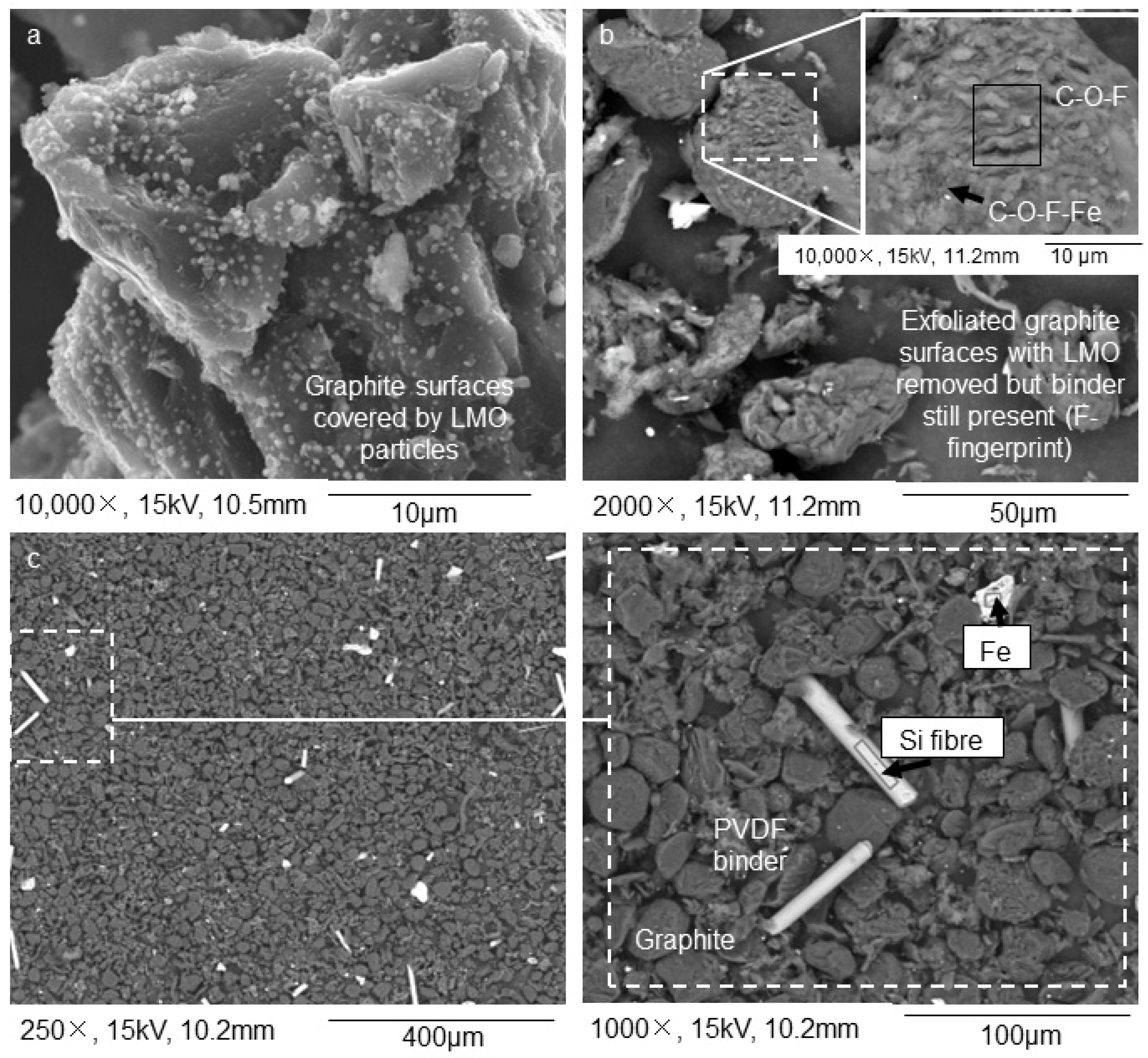
For the NL55 sample (fine fraction after the first sieving stage), a single stage of leaching was inefficient, and small LMO particles still occurred on the surfaces of graphite particles (Figure 5a). Only after adding an additional ultrasound step could the sub-micrometric particles be removed (Figure 5b). Like NL54, the precipitates contained leached LMO. NL63, the precipitate formed after 1 h of leaching at 1 M, contained a large amount of Mn/MnO (Table 1). The Mn/MnO ratio then lowers rapidly with an increase in time (NL64–NL68), indicating that this component is easily removed by acid leaching (Table 1). To strengthen this observation, it is also noted that for the 3 M trials, the Mn/MnO concentration is very low (NL69–NL72) and reaches 0% after 5 h and 6 h (NL73 and NL74) (Table 1). Ni and Co are more obstinate. In the case of Ni, a rapid decrease in concentration with time is only seen after treatment with 3 M citric acid (NL69–NL74) indicating that it is not as easily removed as Mn/MnO (Table 1). In the case of Co, it seems that after 6 h at 3 M citric acid concentration (NL74), this component is still present in low concentrations in the precipitate, indicating that it has not been completely removed (Table 1). The NL63 precipitate has a high concentration of Li but then decreases rapidly and reaches near zero after 6 h (NL68) (Table 1). The same trend is observed for the 3 M citric acid samples (Table 1).
When considering the process refinement stage of the NL55 leached sample, three components are retrieved: NL60, NL61, and NL62. NL60 and NL62 are considered final purified graphite products (yield = 5.6 and 7.2 wt.%, respectively) (Figure 5c) with a size distribution of <25 µm and <45 µm, respectively. NL61 is a coarse >45 µm fraction containing a mixture of graphite, porous PVDF binder, and plastics (yield = 5.1 wt.%). When considering the carbon in these three samples, NL60 and NL62 have total carbon weight percentages above 85 (total carbon), graphitic carbon weight percentages of 65 and 83, respectively (TGA), and graphitic carbon volume percentages of 79 and 58, respectively (petrography) (Table 2). This implies that the organic carbon can be burned off easily through roasting or part of it pyrolyzed, leaving the products even more pure than they currently are. Although NL61 has a graphitic carbon content of 53.45 wt.%, it has a relatively high content of organic carbon and a low content of non-combustible components; therefore, can be purified in a similar fashion, as described above. This is also confirmed by its high total carbon percentage (80 wt.%, Table 2). Although QEMSCAN® shows that the separator categories (binder and polymers) are mostly found in the smaller particles of the samples (<50 µm), for NL62, the larger particles (50–1000 µm) also contain a substantial amount of separator (Table 3). Apart from graphite, these samples have minor levels of organic carbon and only trace levels of other non-combustible components (Table 3). The non-combustible components belong mainly to the QEMSCAN® “Unspecified” category (56–92 area%), which contains Al oxides (Table 3). Although the “Other” category was also detected with automated mineralogy, its volume in samples NL60, NL621, and NL62 decreased in relation to the oversized samples NL57 and NL59 and the float material NL56, which indicates that they are relatively coarse materials and evideneces the heterogeneity of this category (Table 3). The cathode material ranges between 0.34 area% and 16.81 area% (Table 3). The highest volumes of cathode material in each sample studied occur in the fine fraction, which is expectable owing to the low size of the LMO grains. Finally, QEMSCAN® showed low percentages of current collectors (Al and Cu foils), which is due to their ductile nature which makes milling difficult; consequently, the area percentages are low (Table 3). XRD showed that the as-received sample (NL50) contained two major Li-bearing phases and a carbon phase (graphite) (Figure 4a). The peaks associated with the Li-bearing phases became less pronounced and the carbon phase more pronounced in the concentrated samples (Figure 4b–d). This is an indication of the removal of Li-bearing phases during leaching and the concentration of graphite in these samples. Other phases present in the concentrated samples include Cu-, Al-, Fe-, and Si-bearing phases. Furthermore, XRF analysis showed that Co remains in the samples after leaching (Table 1). This indicates the obstinacy that Co shows to acids and confirms the residual Co in the NL75 sample. Si/SiO2 and Fe/FeO are also present in high amounts (Table 1). The NL55 sample has a Li concentration of 25000 mg/kg and in its processed samples (NL60–NL62), the concentration drops to between ~545 mg/kg and ~880 mg/kg.
3. Methodology
The as-received BM sample used during experimentation was supplied by an existing LIB recycling plant which uses a two-stage mechanical treatment process (a crushing line followed by a magnetic and mechanical separation unit) to obtain their BM product. For this study, the as-received BM sample was subjected to a series of mineral processing steps, consisting of pre-treatment, acid leaching, and refinement stages, to recover the graphite as main product and LMO and Cu and Al foils as by-products.
3.1. Sample Characterization
The elemental, mineralogical, and morphological compositions of the as-received BM and mineral processed samples were determined.
To ensure that the samples were homogenous for characterization, size reduction was applied to fractions >75 μm. A Polytron (Polytron® PT 2500 E, Kinematica AG, Malters, Switzerland) operating at 5000 rpm with water as a liquid medium and a 4 h residence time was used. Due to the slicing effect of the Polytron blade, ductile components, such as the Cu foils and plastics, could also be reduced in size. For the dried precipitates after leaching, manual reduction was implemented using a mortar and pestle.
The following techniques were used for characterization: XRF, ICP-OES, total carbon through the Leco C method, TGA, XRD, petrography, SEM–EDS, and automated mineralogy analysis (QEMSCAN®). SEM–EDS was also used during trials to “pre-check” results.
XRF analysis was outsourced to CRS Laboratories in Finland. Seven grams of each sample were finely ground together with wax and pressed into a wax pellet. The pressed sample pellet was then analyzed with a Panalytical Axios 3 kW WD-XRF (Malvern Panalytical, Malvern, United Kingdom) and the results were calculated with a PRFPO calculation program. The method is semi-quantitative for various matrixes in analyte concentrations of 0–100%. The data was normalized and the major elements (Al, Cu, Ni, Co, Mn, Si, and Fe) and major oxides (Al2O3, SiO2, MnO, and FeO) are presented in-text. Samples that contained a lot of organic material gave a very low oxide sum in XRF analysis. The accuracy of analysis is affected by this and can be enhanced if carbon and/or loss on ignition results are taken into account.
ICP-OES analysis for Li determination was outsourced to CRS Laboratories in Finland. A 0.25 g sample was leached in concentrated aqua regia (1:3 nitric acid (HNO3) and hydrochloric acid (HCl)), diluted with dilute HCl, and analyzed with a Thermo Fisher Scientific iCAP PRO ICP-OES analyzer (Thermo Fisher Scientific, Waltham, USA), in which the stability was monitored with control solutions. Quality control included certified reference materials, blank samples, and duplicate assays. Samples with a high carbon content are usually pre-combusted. However, these samples were analyzed without pre-combustion since it caused the samples to burn into the crucible.
The total carbon (summation of organic carbon and graphitic carbon) analysis was outsourced to CRS Laboratories Oy in Finland and measured by the Leco C method. A 10–100 mg sample was combusted and analyzed with a LECO CS744 analyzer (Leco Corporation, St. Joseph, USA). The sample was combusted with accelerator reagents in an induction oven under oxygen flow. The formed CO2 and SO2 gases were led into the detectors and the instrument calculated the analyte percentage in the sample. Quality control included certified reference materials, blank samples, and duplicate assays.
The TGA analysis was completed at the Universidade do Porto, Portugal, using a LT 9/11/SW muffle furnace from Nabertherm GmbH (Lilienthal, Germany). For the TGA analysis, to ensure that moisture does not affect the analysis, samples were dried for 24 h at 50 °C before commencing with the analysis. To determine mass loss with temperature, samples were placed in ceramic crucibles (pre-heated to 950° C and cooled to equilibrium in a desiccator) and heated from room temperature to 500 °C at a rate of 8 °C/min, and then from 500 °C to 950 °C at a rate of 7.5 °C/min. The temperature was kept at 950 °C for 2 h. The mass loss below 650 °C was ascribed to the loss in organic carbon while the loss above 650 °C was ascribed to graphite. This threshold value was chosen based on anode graphite (99.95% Loss on Ignition from Sigma–Aldrich, Lisbon, Portugal), plastics (hand-picked from samples with a high plastic content as observed with SEM–EDS analysis), and PVDF binder (thin films prepared beforehand) standards. The samples chosen for the TGA experiments include the final concentrates which, as indicated via petrography and SEM–EDS analyses, contain mainly graphite, PVDF, and plastics. Other components in LIB are partially released with an increase in temperature; therefore, the remainder of the samples were not subjected to TGA due to their elevated inorganic contents.
The mineralogical composition of the samples was identified using XRD at Swerim AB. A PANalytical Empyrean X-ray diffractometer (Malvern Panalytical, Malvern, United Kingdom) in θ-θ geometry was used for the XRD measurement with Cu Ka radiation (λ = 0.154184 nm), a beam current of 40 mA, and a beam voltage of 45 mV. The XRD pattern was measured in the 2θ range of 20–90° with a step size of 0.026°/s. A curved graphite crystal monochromator mounted before a PIXcel 3D-detector was used to take care of the fluorescence due to the presence of Fe in the samples. The measured data were evaluated for phase identification using HighScore Plus (v4.7, PANalytical B.V., Almelo, The Netherlands) software and FIZ-NIST ICSD (Inorganic Crystal Structure Database) database, version 2022.1.
Petrographic analysis was conducted at the Universidade do Porto. Polished blocks were prepared using [32]. Analysis was conducted on the polished blocks using a Leica DM4500 P LED reflected-light petrographic microscope (Leica Microsystems, Wetzlar, Germany) with an oil immersion objective and a combined magnification of ×500, controlled by the software Fossil (Hilgers Technisches Büro, Königswinter, Germany). For quantification purposes, 550 particles in each block were counted based on the following six-class system (results expressed as a vol%):
- graphite (includes dense and flake morphotypes);
- binder mixture (binder and small impurities embedded in the binder);
- foils (Al and Cu);
- organic carbon (plastics and other carbonaceous material that is fluorescent under ultraviolet light);
- LMO (includes blue spherical particles described as Li-Mn-O, white spherical particles described as Li-Ni-Co-O and Li-Ni-Mn-Co-O, and blue angular particles described as Li-Co-O);
- other (includes Fe and Si).
For the SEM–EDS analysis, powders mounted on carbon tape and polished blocks of the samples (using the [32] standard) were used. The samples were coated with a carbon layer before analysis. These were conducted at the Centro de Materiais da Universidade do Porto. A high-resolution (Schottky) Environmental Scanning Electron Microscope with X-ray Microanalysis and Backscattered Electron Diffraction Pattern Analysis (FEI Quanta 400 FEG ESEM/EDAX Genesis X4M, FEI Company, Hillsboro, USA) was used.
The QEMSCAN® analysis [33,34,35] was conducted at the Camborne School of Mines, University of Exeter, UK. Sample measurement used iMeasure 4.2SR1 software and data processing used iDiscover 4.2SR1 and 4.3 software [36]. The samples (polished blocks using the [32] standard) were carbon coated to 25 nm prior to analysis using an Agar carbon coater. The QEMSCAN® 4300 system settings were 25 kV, 5 nA, a 1000 X-ray count rate per pixel, and a working distance of 22 mm under high vacuum and beam calibration every 30 min. Sample measurement used the PMA measurement mode to analyze the samples, with two PMA fractions examined per sample, a coarse and fine fraction to cover the large range of particle sizes in the samples. The coarse fraction was set to measure particles >50 μm using 5 μm X-ray resolution, 1500 μm field size, and ×44 magnification. The fine fraction was set to measure particles <50 μm using 1 μm X-ray resolution, 300 μm field size, and ×319 magnification. After data collection, data processing and database development were essential due to the non-standard nature of the material. This classified all phases producing around 45 categories, which were subsequently grouped into 7 categories according to the requirements of the project (Table 4). This process benefited from other analysis data from the project, as well as the details in [37]. This also needed to consider the limitations of the method in terms of elemental detection limits and range (see [36], Section 7 for details). The carbonaceous materials that include organic polymers and anode graphite are hardly detected or not detected at all due to the spectrum of carbonaceous material and the resin used in the blocks being similar. The fluorine in the PVDF binder allowed the detection of this component even though it contains carbon. Therefore, in this study, the QEMSCAN® analysis was used to assess the “impurities” left in graphite concentrates, such as metallic components, minerals, and inorganic polymers.
3.2. Trials for Removing PVDF Binder
To increase the efficiency of the graphite recovery process, it is first necessary to lower the influence of the PVDF binder on the separation process efficiency. In this paper, the usage of ultrasound for PVDF binder removal was tested by using PVDF cast on Al foils. It was assumed that the results of the Al foils will also be relevant in the case of actual LIB, which contains PVDF on Cu and Al foils and is embedded with LMO and graphite particles.
As a first step, PVDF was cast on Al foil. PVDF powder (CAS: 24937-79-9) was purchased from Sigma–Aldrich, Lisbon, Portugal. N-Methyl-2-pyrrolidone (NMP) solvent (CAS: 872-50-4) was then used to create a workable viscous slurry with the PVDF. As a first trial, 100 mg of PVDF was mixed with 0.19 mL of NMP. This ratio (1:2 wt.%) was based on the literature [38,39,40]. However, it was found that the slurry was not viscous enough to cast on Al foil and the solid-to-liquid ratio was increased stepwise until a workable viscous slurry was obtained. This ratio was found to be 100 mg solid to 0.25 mL liquid (1:2.6 wt.%). Al foil was glued to a glass film, and with a razor blade, the PVDF–NMP slurry was smeared across the Al tape so that a thin film formed. Drying at 120 °C on a hot plate and overnight in a vacuum oven ensured that the NMP evaporated, leaving only PVDF binder behind.
The ultrasound trials were aimed at removing the PVDF binder from the Al foil by ultrasound waves using water as a liquid medium. The usage of water is preferred over other media due to economic and environmental considerations. An Ultrasonic Processor UP200St from Hielscher with a Sonotrode S26d40 (Teltow, Germany) was used in the trials. Exposure time and amplitude were varied. Energy and temperature were measured. The liquid volume (500 mL) and pulse (100%) were kept constant. For the exposure time trials, amplitude (20%) was kept constant while exposure time was varied (1 h, 2 h, 3 h, 6 h, 12 h, 18 h, 24 h). To determine the influence of amplitude, three sets of experiments were conducted. In the first, the exposure time was maintained at 30 min while the amplitude was varied (20%, 50%, 80%). In the second, the exposure time was maintained at 2 h while the amplitude was varied (20%, 50%, 80%). In the third, the exposure time was maintained at 12 h while the amplitude was varied (20%, 60%, 100%).
Ultrasound trials were also conducted on a graphite anode powder standard (99.95% loss on ignition from Sigma–Aldrich, Lisbon, Portugal) to determine the influence of ultrasound waves on the surface properties and size reduction of graphite particles. Trials at a 100% amplitude and 2 h exposure time, a 20% amplitude and 2 h exposure time, and a 20% amplitude and 12 h exposure time were conducted. SEM–EDS analysis was used to determine the surface and size reduction changes.
After exposure to ultrasound waves, microscopic analysis was conducted to determine the crack formation and propagation behavior. A Leica DM4500 P LED reflected-light petrographic microscope with an oil immersion objective and a combined magnification of ×500, controlled by the software Fossil (Hilgers Technisches Büro, Königswinter, Germany) was used. The ×5 and ×10 objectives under UV light were used. Seeing as the PVDF binder is fluorescent and the Al foil is not, the formation of cracks was easily identified (see Figure 1).
3.3. Graphite Recovery Process Flow Diagram
The BM as-received sample was subjected to a series of mineral processing steps, consisting of pre-treatment, acid leaching, and refinement stages, to recover the graphite. The final process flow diagram (PFD) and sample nomenclature are provided (Figure 2).
The BM as-received sample (NL50) was split into two fractions: >250 µm (NL54) and <250 µm (NL55). Analyses showed that the NL54 and NL55 samples differed in composition, where Cu and Al foils are enriched in the coarse fraction and LMO and graphite in the finer fraction. The size separation thus allowed for different processing of the two fractions based on their unique characteristics. Size separation was conducted on a dry basis using manual sieving.
From the literature study, it was seen that leaching of LMO with weak organic acids is viable, has a smaller environmental footprint than using inorganic acids, and possibly has lower costs than the inorganic alternatives.
For leaching NL54, a three-step process was implemented. Citric acid monohydrate powder (210.14 g/mole) was purchased from Sigma–Aldrich, Lisbon, Portugal, and dissolved into water to form a 1 M solution. Subsequently, a 0.06 g/mL sample was added to this solution. The solution was then soaked at 75 °C in a pre-heated LT 9/11/SW muffle furnace from Nabertherm GmbH (New Castle, USA) for 1 h. Then, the solution was stirred at 900 rpm for 30 min while being kept at 75 °C. For this purpose, an IKA® Ministar 20 control stirrer (IKA, Staufen, Germany) and an IKA® RCT basic hot plate (IKA, Staufen, Germany) were used. The speed was then increased to 1200 rpm and stirred for 30 min at 75 °C. This three-step process of soaking and stirring was repeated three times and was based on the results from PVDF-binder removal trials that have been made previously in which it was found that binder peels from foils at 75 °C and 2 h. Stirring was added to ensure that all particles and particle surfaces are exposed to the acid for leaching purposes. After leaching, a fraction of the sample floated (NL56) on the citric acid; therefore, a sink-float step was added. A membrane filter was used to separate the solid and liquid fractions of both the float and sink products. The liquid fractions were dried until a solid precipitate, enriched in leached LMO, remained (NL75). The solid fractions were washed with water and filtered several times to remove any residual solution. The solid fraction that sank in citric acid was refined through a series of size separation and comminution steps. Manual size separation at 500 µm delivered a coarse fraction (NL57) and a fine fraction, the latter was enriched in anode chunks and subsequently subjected to comminution to break apart these chunks and the PVDF binder that binds these chunks together. This was accomplished through abrasion breakage by ultrasound followed by attrition breakage by using a Polytron (Polytron® PT 2500 E, Kinematica AG, Malters, Switzerland). PVDF binder removal trials have shown that this material can be torn by using ultrasound, while [7] used attrition to shear the PVDF binder from LIB. Water was used as a solvent in both processes (0.02 g/mL) and the breakage time was set at two hours for each. The ultrasound was operated at 100% of its maximum amplitude while the Polytron blade was rotating at 5000 rpm. Size separation at 75 µm delivered a coarse fraction (NL58) and the first purified graphite product of this process, in the form of a fine <75 µm fraction (NL59). Sieving was conducted on a dry basis using automatic sieving, where the amplitude was set at 60% of the maximum and the residence time at 20 min.
For the NL55 fraction, it was observed that if the three-step process, implemented on NL54 and described above, is implemented, a saturation of the solution occurs and the leaching process is inefficient. This was noted due to a dark brown coloration of the citric acid (compared to a green coloration for NL54) as well as the unsuccessful removal of LMO as confirmed using SEM–EDS. To determine the point of saturation, the solution (0.04 g/mL sample in 1 M citric acid solution) was stirred at 900 rpm while maintaining the temperature at 75 °C. An ultraviolet spectrum (Varian Cary50Bio spectrophotometer, Agilent, Santa Clara, CA, USA, in the range of 800–200 nm using a quartz cell with path lengths of l = 1 cm) was measured every 20 min, seeing as a notable intensity of color change in the solution was observed with time. Using the absorption at 742 nm (the maximum absorption for all time intervals), the saturation point time was determined at 1 h. Consequently, the solution was filtered (with the membrane filter described previously) every hour and the solids were transferred to a new batch of 1 M citric acid. The liquids were dried to form a solid precipitate (NL63–NL68). To determine the maximum amount of time needed, the change in color was again monitored. After 4 h, the solution became transparent; after 6 h, the process was deemed to be completed. However, SEM–EDS analysis revealed that LMO sub-micrometric particles still occurred on the surfaces of graphite particles even after leaching had been deemed completed. Seeing as the application of ultrasound leads to some exfoliation of graphite layers (binder removal trials), an Ultrasonic Processor UP200St from Hielscher with a Sonotrode S26d40 (Teltow, Germany )was used to remove the small LMO from the graphite surfaces. The amplitude was set to 100% of the maximum. In this case, a 3 M solution was used in a similar fashion as described above, namely that the solution was filtered every hour, for a period of six hours, and the solids transferred to a new batch of citric acid after every hour. The filtrated liquids were dried to form a solid precipitate (NL69–NL74). Applying this ultrasound process leads to the removal of small particles from the graphite surfaces through exfoliation. A sink-float stage was not added to the NL55 fraction leaching process because the fraction floating in citric acid after leaching had a negligible amount. After leaching the NL55 sample, the solid fraction was subjected to a size separation stage at 25 µm. The fine fraction (<25 µm; sample NL60) was the second purified graphite product of the process. Sieving was conducted on a dry basis using automatic sieving, where the amplitude was set at 60% of the maximum and the residence time at 40 min. The >25 µm fraction was subjected to the Polytron (5000 rpm for 2 h) to break any anode chunks that might be present in this fraction. Following the breakage by Polytron, size separation at 45 µm delivered a coarse fraction (NL61) and a fine fraction that delivered the final purified graphite product of the process (NL62). Sieving was conducted on a dry basis using automatic sieving where the amplitude was set at 60% of the maximum and the residence time at 20 min.
4. Conclusions
The aim of this paper was to introduce a process for recovering graphite from spent LIB (while simultaneously also removing some of the other LIB components) via acid leaching and physical separation methods.
The proposed graphite recovery process can be implemented, so to speak, “in your backyard”. It utilises simple technologies which are affordable, scalable, and readily available in the market, and, therefore, cost-effective. The designed process seems accessible to micro and large enterprises, and the resulting products may be sent to be processed elsewhere instead of long-distance transportation of spent LIB. Furthermore, these technologies are operated at low temperatures and utilises organic acids for leaching purposes; therefore, they are more considerate to the environment than other technologies implemented in industry. However, at these early stages of the process development, the yields of the product streams are still low and more work is needed to improve this and make the designed process a competitor in the battery recycling market.
The following products and results were delivered:
- a > 500 µm concentrate of Al and Cu foil fragments (18.8 wt.% yield);
- usage of ultrasound to tear and peel PVDF binder from LIB and to exfoliate particle surfaces to increase separation efficiency;
- <25 µm, <45 µm and <75 µm graphite-rich products with 88 wt.%, 85 wt.% and 74 wt.% total carbon and 5.6, 7.2, and 1.5 wt.% yields, respectively;
- precipitated products enriched in Li, Co, Mn, and Ni.
- Future tests include:
- improvement of the products’ yields;
- testing of graphite for possible re-use in manufacturing new LIB and/or other applications;
- testing of the precipitated products as carbon polymers and for recovering Li, Co, Mn, and Ni; and
- testing Al and Cu recovery through an electrostatic separator.
Author Contributions
Conceptualization, C.B. and B.V.; Funding acquisition, G.Y.; Investigation, C.B., A.G. and G.R.; Methodology, C.B., I.K.-B., A.G., G.R. and B.V.; Project administration, E.M. and G.Y.; Resources, I.K.-B., E.M., V.R. and G.Y.; Supervision, B.V.; Writing—original draft, C.B. and G.R.; Writing—review & editing, G.Y. and B.V. All authors have read and agreed to the published version of the manuscript.
Funding
This research was funded by VINNOVA, Sweden (Project no. 2019-03473) and FCT-Portugal (ref. ERA-MIN/0003/2018; project COMPETE 2020 (UIDB/04683/2020); POCI-01-0145-FEDER-007690) under the ERA-MIN2 programme.
Institutional Review Board Statement
Not applicable.
Informed Consent Statement
Not applicable.
Data Availability Statement
The data presented in this study are available on request from the corresponding author. The data are not publicly available as it forms part of the ERA-MIN2 programme.
Acknowledgments
This work was carried out with the support of the ERA-MIN2 programme (2018), the European Commission, and the respective national financier represented in VINNOVA, Sweden (project no. 2019-03473), and Fundação para a Ciência e a Tecnologia, Portugal (ref. ERA-MIN/0003/2018) through the projects projects UIDB/04683/2020 and UIDP/04683/2020 ICT (Institute of Earth Sciences) and POCI-01-0145-FEDER-007690 to the project “Novel Circular Economic Approaches for Efficient Extraction of Valuables from Spent Li-Ion Batteries (NEXT-LIB)”.
Conflicts of Interest
The authors declare no conflict of interest.
References
- Velázquez-Martínez, O.; Valio, J.; Santasalo-Aarnio, A.; Reuter, M.; Serna-Guerrero, R. A critical review of lithium-ion battery recycling processes from a circular economy perspective. Batteries 2019, 5, 68. [Google Scholar] [CrossRef]
- Zhang, Z.; He, W.; Li, G.; Xia, J.; Hu, H.; Huang, J. Ultrasound-assisted Hydrothermal Renovation of LiCoO2 from the Cathode of Spent Lithium-ion Batteries. Int. J. Electrochem. Sci. 2014, 9, 3691–3700. [Google Scholar]
- Silveira, A.; Santana, M.; Tanabe, E.; Bertuol, D. Recovery of valuable materials from spent lithium ion batteries using electrostatic separation. Int. J. Miner. Process. 2017, 169, 91–98. [Google Scholar] [CrossRef]
- Bertuol, D.A.; Toniasso, C.; Jiménez, B.M.; Meili, L.; Dotto, G.L.; Tanabe, E.H.; Aguiar, M.L. Application of spouted bed elutriation in the recycling of lithium ion batteries. J. Power Sources 2015, 275, 627–632. [Google Scholar] [CrossRef]
- Zhang, W.; Xu, C.; He, W.; Li, G.; Huang, J. A review on management of spent lithium ion batteries and strategy for resource recycling of all components from them. Waste Manag. Res. J. Sustain. Circ. Econ. 2017, 36, 99–112. [Google Scholar] [CrossRef]
- Zhu, S.; He, W.; Li, G.; Zhou, X.; Huang, J.; Zhang, X. Recovering copper from spent Lithium ion battery by a mechanical separation process. In Proceedings of the 2011 International Conference on Materials for Renewable Energy & Environment, Shangai, China, 20–22 May 2011; pp. 1008–1012. [Google Scholar] [CrossRef]
- Vanderbruggen, A.; Sygusch, J.; Rudolph, M.; Serna-Guerrero, R. A contribution to understanding the flotation behavior of lithium metal oxides and spheroidized graphite for lithium-ion battery recycling. Colloids Surfaces A Physicochem. Eng. Asp. 2021, 626, 127111. [Google Scholar] [CrossRef]
- Yu, J.; He, Y.; Ge, Z.; Li, H.; Xie, W.; Wang, S. A promising physical method for recovery of LiCoO 2 and graphite from spent lithium-ion batteries: Grinding flotation. Sep. Purif. Technol. 2018, 190, 45–52. [Google Scholar] [CrossRef]
- Javorsky da Costa, A.; Matos, J.F.; Bernardes, A.M.; Müller, I.L. Beneficiation of cobalt, copper and aluminium from wasted lithium-ion batteries by mechanical processing. Int. J. Miner. Process 2015, 145, 77–82. [Google Scholar] [CrossRef]
- Jin, Y.J.; Mei, G.J.; Li, S.Y. Leaching of cobalt from LiCoO2 cathode in spent lithium-ion batteries with sulfuric acid by ultrasonic. Hydrometall. China 2006, 25, 97–99. (In Chinese) [Google Scholar]
- Meng, F.; Liu, Q.; Kim, R.; Wang, J.; Liu, G.; Ghahreman, A. Selective recovery of valuable metals from industrial waste lithium-ion batteries using citric acid under reductive conditions: Leaching optimization and kinetic analysis. Hydrometallurgy 2019, 191, 105160. [Google Scholar] [CrossRef]
- Xu, M.; Kang, S.; Jiang, F.; Yan, X.; Zhu, Z.; Zhao, Q.; Teng, Y.; Wang, Y. A process of leaching recovery for cobalt and lithium from spent lithium-ion batteries by citric acid and salicylic acid. RSC Adv. 2021, 11, 27689. [Google Scholar]
- Pant, D.; Dolker, T. Green and facile method for the recovery of spent Lithium Nickel Manganese Cobalt Oxide (NMC) based Lithium ion batteries. J. Waste Manag. 2017, 60, 689–695. [Google Scholar]
- Bahaloo-Horeh, N.; Mousavi, S.M. Enhanced recovery of valuable metals from spent lithium-ion batteries through optimization of organic acids produced by Aspergillus niger. Waste Manag. 2017, 60, 666–679. [Google Scholar] [CrossRef]
- Zhang, G.; He, Y.; Wang, H.; Feng, Y.; Xie, W.; Zhu, X. Application of mechanical crushing combined with pyrolysis-enhanced flotation technology to recover graphite and LiCoO2 from spent lithium-ion batteries. J. Clean. Prod. 2019, 231, 1418–1427. [Google Scholar] [CrossRef]
- Mousa, E.; Hu, X.; Ånnhagen, L.; Ye, G.; Cornelio, A.; Fahimi, A.; Bontempi, E.; Frontera, P.; Badenhorst, C.; Santos, A.C.; et al. Characterization and Thermal Treatment of the Black Mass from Spent Lithium-Ion Batteries. Sustainability 2023, 15, 15. [Google Scholar] [CrossRef]
- Lee, C.K.; Rhee, K.-I. Preparation of LiCoO2 from spent lithium-ion batteries. J. Power Sources 2002, 109, 17–21. [Google Scholar] [CrossRef]
- He, Y.; Yuan, X.; Zhang, G.; Wang, H.; Zhang, T.; Xie, W.; Li, L. A critical review of current technologies for the liberation of electrode materials from foils in the recycling process of spent lithium-ion batteries. Sci. Total Environ. 2021, 766, 142382. [Google Scholar] [CrossRef]
- Chen, X.; Ma, H.; Luo, C.; Zhou, T. Recovery of valuable metals from waste cathode materials of spent lithium-ion batteries using mild phosphoric acid. J. Hazard. Mater. 2017, 326, 77–86. [Google Scholar] [CrossRef]
- Li, L.; Qu, W.; Zhang, X.; Lu, J.; Chen, R.; Wu, F.; Amine, K. Succinic acid-based leaching system: A sustainable process for recovery of valuable metals from spent Li-ion batteries. J. Power Sources 2015, 282, 544–551. [Google Scholar] [CrossRef]
- Sandhya, C.P.; John, B.; Gouri, C. Synthesis, characterization and electrochemical evaluation of mixed oxides of nickel and cobalt from spent lithium-ion cells. RSC Adv. 2016, 6, 114192–114197. [Google Scholar]
- Xin, Y.; Guo, X.; Chen, S.; Wang, J.; Wu, F.; Xin, B. Bioleaching of valuable metals Li, Co, Ni and Mn from spent electric vehicle Li-ion batteries for the purpose of recovery. J. Clean. Prod. 2016, 116, 249–258. [Google Scholar] [CrossRef]
- Song, D.; Wang, X.; Zhou, E.; Hou, P.; Guo, F.; Zhang, L. Recovery and heat treatment of the Li(Ni1/3Co1/3Mn1/3)O2 cathode scrap material for lithium ion battery. J. Power Sources 2013, 232, 348–352. [Google Scholar] [CrossRef]
- Xu, Y.; Song, D.; Li, L.; An, C.; Wang, Y.; Jiao, L.; Yuan, H. A simple solvent method for the recovery of LixCoO2 and its applications in alkaline rechargeable batteries. J. Power Sources 2014, 252, 286–291. [Google Scholar] [CrossRef]
- Song, X.; Hu, T.; Liang, C.; Long, H.L.; Zhou, L.; Song, W.; You, L.; Wu, Z.S.; Liu, J.W. Direct regeneration of cathode materials from spent lithium iron phosphate batteries using a solid phase sintering method. RSC Adv. 2017, 7, 4783–4790. [Google Scholar] [CrossRef]
- He, L.-P.; Sun, S.-Y.; Mu, Y.-Y.; Song, X.-F.; Yu, J.-G. Recovery of Lithium, Nickel, Cobalt, and Manganese from Spent Lithium-Ion Batteries Using l-Tartaric Acid as a Leachant. ACS Sustain. Chem. Eng. 2017, 5, 714–721. [Google Scholar] [CrossRef]
- Nayaka, G.P.; Pai, K.V.; Manjanna, J.; Keny, S.J. Use of mild organic acid reagents to recover the Co and Li from spent Li-ion batteries. Waste Manag. 2016, 51, 234–238. [Google Scholar] [CrossRef]
- Yang, L.; Xi, G.; Lou, T.; Wang, X.; Wang, J.; He, Y. Preparation and magnetic performance of Co0.8Fe2.2O4 by a sol–gel method using cathode materials of spent Li-ion batteries. Ceram. Int. 2016, 42, 1897–1902. [Google Scholar] [CrossRef]
- Zhang, G.; He, Y.; Feng, Y.; Wang, H.; Zhu, X. Pyrolysis-ultrasonic-assisted flotation technology for recovering graphite and LiCoO2 from spent Lithium-ion battery. ASC Sustain. Chem. Eng. 2018, 6, 10896–10904. [Google Scholar]
- Liu, J.; Wang, H.; Hu, T.; Bai, X.; Wang, S.; Xie, W.; Hao, J.; He, Y. Recovery of LiCoO2 and graphite from spent lithium-ion batteries by cryogenic grinding and froth flotation. Miner. Eng. 2020, 148, 106223. [Google Scholar] [CrossRef]
- Yang, L.; Xu, G.; Feng, Q.; Li, Y.; Zhao, E.; Ma, J.; Fan, S.; Li, X. Separation and recovery of carbon powder in anodes from spent lithium-ion batteries to synthesize graphene. Sci. Rep. 2019, 9, 9823. [Google Scholar] [CrossRef]
- ISO (International Organisation for Standardisation). ISO 7404-2 Methods for the Petrographic Analysis of Coals. Part 2: Methods of Preparing Coal Samples; ISO: Geneva, Switzerland, 2009. [Google Scholar]
- Gottlieb, P.; Wilkie, G.; Sutherland, D.; Ho-Tun, E.; Suthers, S.; Perera, K.; Jenkins, B.; Spencer, S.; Butcher, A.; Rayner, J. Using quantitative electron microscopy for process mineralogy applications. JOM 2000, 52, 24–25. [Google Scholar] [CrossRef]
- Goodall, W.R.; Scales, P.J.; Butcher, A.R. The use of QEMSCAN and diagnostic leaching in the characterisation of visible gold in complex ores. Miner. Eng. 2005, 18, 877–886. [Google Scholar] [CrossRef]
- Goodall, W.R.; Scales, P.J. An overview of the advantages and disadvantages of the determination of gold mineralogy by automated mineralogy. Miner. Eng. 2007, 20, 506–517. [Google Scholar] [CrossRef]
- Rollinson, G.K.; Andersen, J.C.Ø.; Stickland, R.J.; Boni, M.; Fairhurst, R. Characterisation of non-sulphide zinc deposits using QEMSCAN®. Miner. Eng. 2011, 24, 778–787. [Google Scholar] [CrossRef]
- Dadé, M.; Wallmach, T.; Laugier, O. Detailed Microparticle Analyses Providing Process Relevant Chemical and Microtextural Insights into the Black Mass. Minerals 2022, 12, 119. [Google Scholar] [CrossRef]
- Handel, P.; Stangl, C.; God, C.; Filzwieser, M.; Uhlig, F.; Schroettner, H.; Koller, S. About Microwave Solvothermal Synthesis of Solid Solutions LiFexMn1-xPO4/C and Their Electrochemical Properties. ECS Trans. 2015, 66, 127–137. [Google Scholar] [CrossRef]
- Santee, S.G.; Ravdel, B.; Gulbinska, M.K.; Gnanaraj, J.S.; DiCarlo, J.F. Optimizing electrodes for lithiu-ion cells. In Lithium-Ion Battery Materials and Engineering—Current Topics and Problems from the Manufacturing Perspective; Gulbinska, M.K., Ed.; Springer: London, UK, 2014; pp. 63–88. [Google Scholar] [CrossRef]
- Wood, D.L.; Quass, J.D.; Li, J.; Ahmed, S.; Ventola, D.; Daniel, C. Technical and economic analysis of solvent-based lithium-ion electrode drying with water and NMP. Dry. Technol. 2017, 36, 234–244. [Google Scholar] [CrossRef]
Figure 1.
Ultrasound trials: Crack formation and propagation in PVDF binder at different exposure times to ultrasound waves (wave amplitude = 20%; liquid volume = 500 mL). All images were adjusted to 35% brightness for quality purposes (10× objective). The Al tape is the darker shades and the PVDF binder is the lighter shades (see bottom right image).
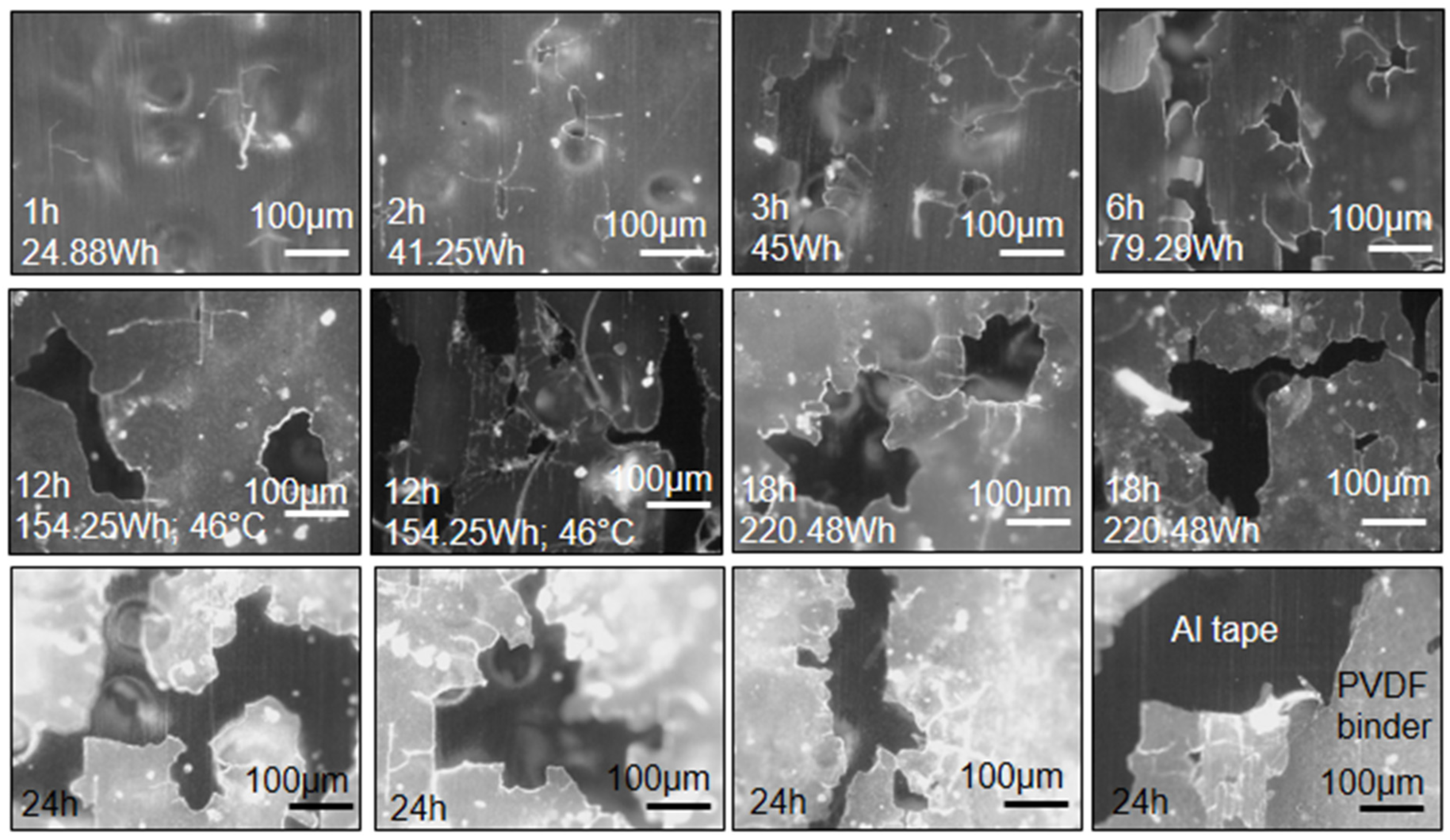
Figure 2.
Graphite recovery process flow diagram with sample nomenclature (NL#) indicated.
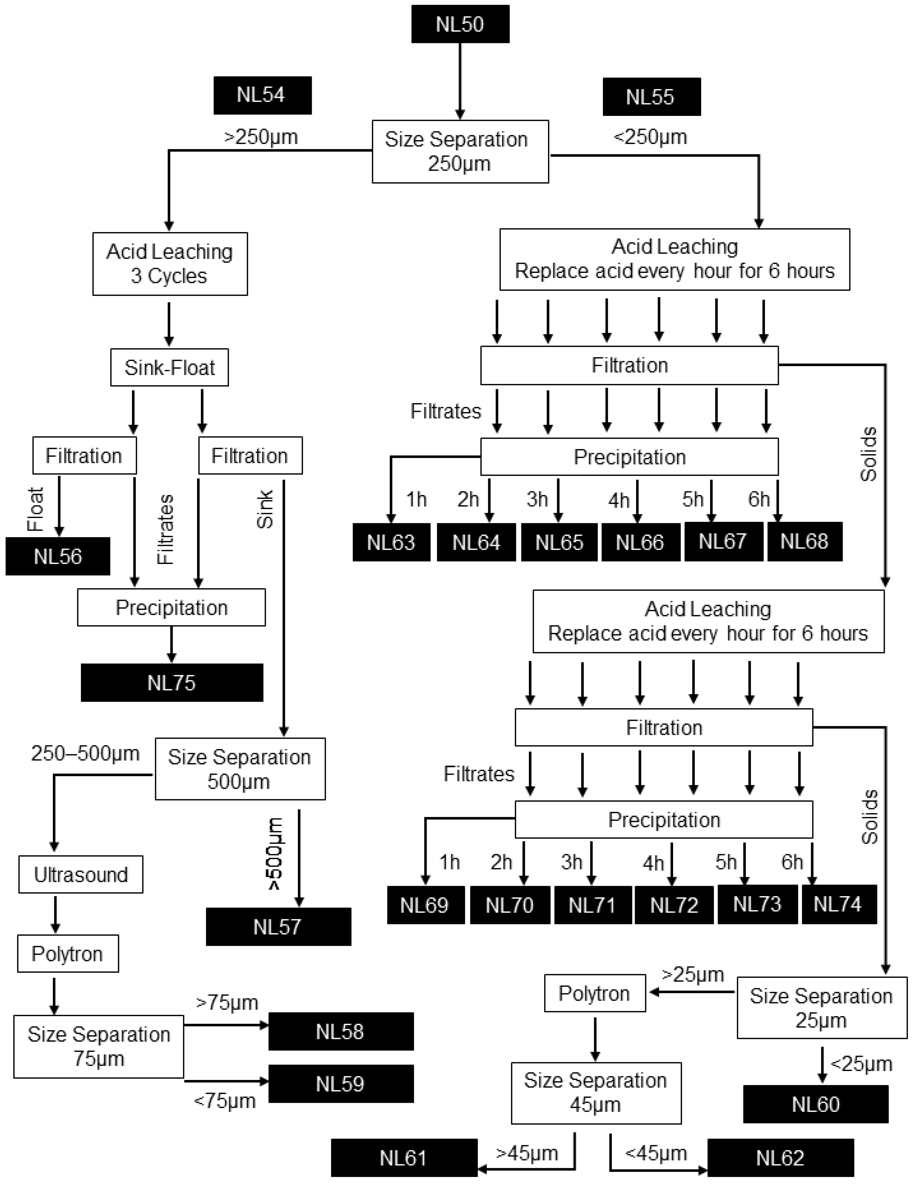
Figure 3.
Results from the graphite recovery process conducted on the >250 µm fraction (initial stages): (a) the solid residue fraction after leaching that floated on citric acid consisted of PVDF binder with LMO particles removed; (b) the precipitate fraction after leaching that did not float on citric acid, shows minute Cu and leached LMO particles; (c) solid residue after leaching that did not float on citric acid shows anode chunks and PVDF binder with the LMO particles removed; (d) further size separation of the solid fraction at 500 µm and then 75 µm led to a > 500 µm fraction enriched in Al, Cu, and plastics; (e) a < 75 µm fraction enriched in graphite. SEM–EDS BSE mode was used for the acquisition of the images. The acquisition of the images was performed on powdered samples.
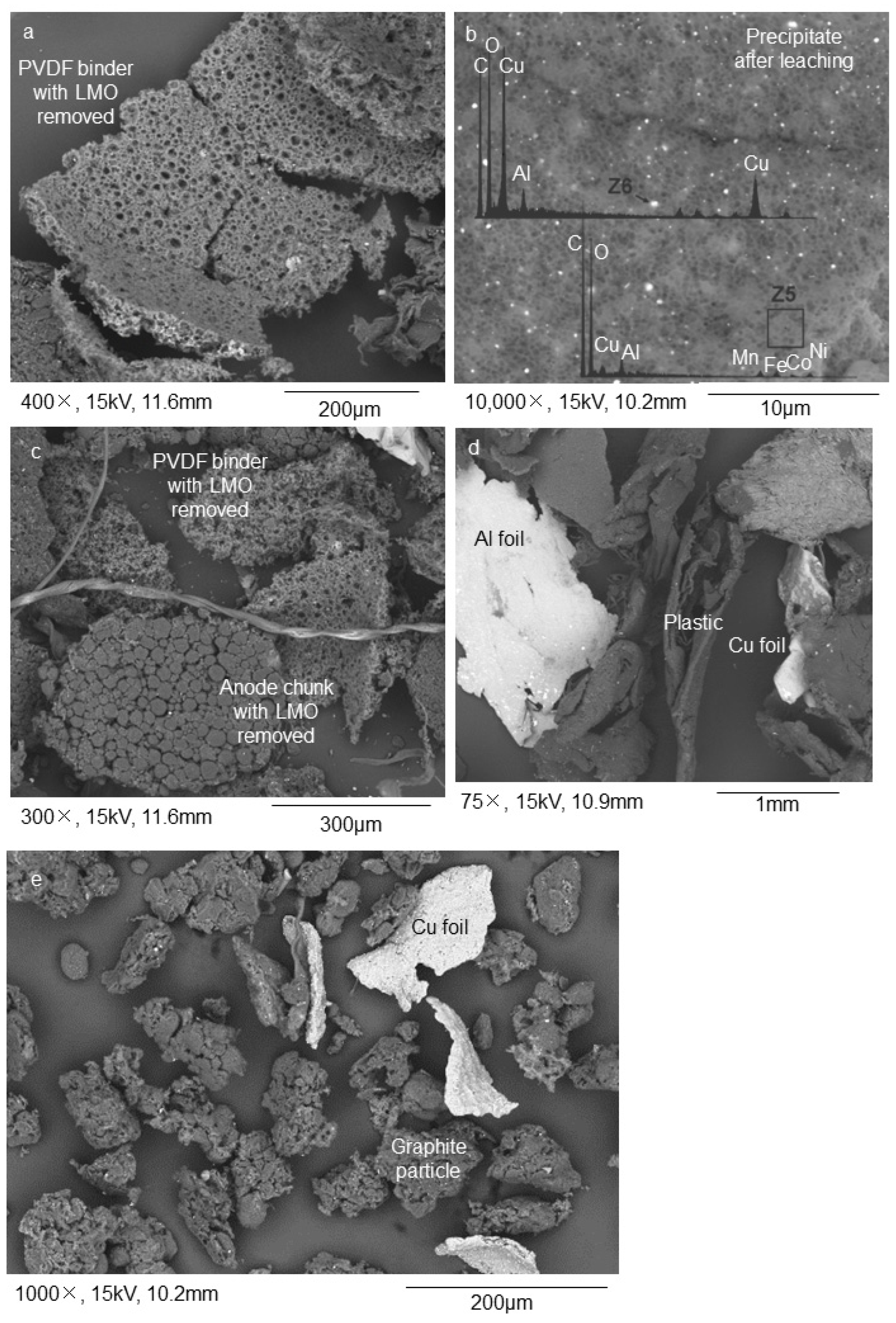
Figure 4.
XRD spectra retrieved on the as-received and final products: (a) NL50; (b) NL59; (c) NL62; (d) NL60. The graphite signal at 27 [°2 Th.] is dominant in the products, which indicates that the graphite is the dominant phase in these samples, while the as-received sample also has strong signals of LMO components.

Figure 5.
Results from the graphite recovery process conducted on the <250 µm fraction: (a) After a first stage of leaching, LMO sub-micrometric particles still occur on the surfaces of graphite particles; (b) After a second stage of leaching combined with ultrasonication (for surface exfoliation purposes), the LMO particles are removed from the surfaces of graphite particles but traces of PVDF binder are still found on the surfaces of graphite particles; (c) Further size separation refinement trials lead to the enrichment of graphite in the <25 µm and <45 µm fractions. SEM–EDS BSE mode was used for the acquisition of the images. The images were acquired on powdered samples.


Table 1.
XRF and ICP-OES.
| NL50 | NL54 | NL55 | NL56 | NL57 | NL58 | NL59 | NL60 | NL61 | NL62 | NL63 | NL64 | NL65 | NL66 | NL67 | NL68 | NL69 | NL70 | NL71 | NL72 | NL73 | NL74 | NL75 | |
|---|---|---|---|---|---|---|---|---|---|---|---|---|---|---|---|---|---|---|---|---|---|---|---|
| XRF—elemental composition (normalized %) | |||||||||||||||||||||||
| Cu | 23.06 | 40.13 | 3.90 | 3.43 | 76.91 | 62.76 | 61.25 | 0.98 | 2.16 | 1.98 | 7.60 | 9.97 | 8.59 | 6.04 | 7.71 | 2.96 | 0.60 | 0.65 | 0.50 | 0.00 | 0.00 | 0.00 | 19.43 |
| Ni | 31.52 | 22.58 | 41.49 | 20.61 | 5.42 | 10.03 | 13.44 | 6.79 | 12.65 | 9.28 | 14.22 | 44.26 | 49.73 | 57.86 | 51.39 | 37.06 | 66.61 | 59.75 | 49.17 | 42.38 | 31.58 | 26.95 | 26.77 |
| Co | 12.28 | 8.29 | 17.23 | 5.54 | 1.31 | 2.66 | 1.99 | 35.60 | 13.43 | 20.96 | 6.65 | 19.09 | 25.04 | 19.43 | 21.07 | 13.83 | 20.98 | 22.65 | 25.59 | 29.14 | 33.08 | 35.93 | 10.97 |
| Si | 1.94 | 2.51 | 1.70 | 48.75 | 4.78 | 8.74 | 12.15 | 20.14 | 25.55 | 23.98 | 2.69 | 0.00 | 0.00 | 0.00 | 0.00 | 29.64 | 0.00 | 0.00 | 0.00 | 0.00 | 0.00 | 0.00 | 0.00 |
| Fe | 6.38 | 5.92 | 5.28 | 4.87 | 1.77 | 1.41 | 2.69 | 20.61 | 13.76 | 24.51 | 9.28 | 5.07 | 3.58 | 4.32 | 5.14 | 4.94 | 0.99 | 2.16 | 5.02 | 0.00 | 15.04 | 0.00 | 22.03 |
| Mn | 20.93 | 14.61 | 27.29 | 4.65 | 1.13 | 2.03 | 0.48 | 1.92 | 4.72 | 2.82 | 55.38 | 17.91 | 7.87 | 7.34 | 7.19 | 4.94 | 9.54 | 12.08 | 13.55 | 13.25 | 0.00 | 0.00 | 18.87 |
| XRF—oxide composition (normalized %) | |||||||||||||||||||||||
| SiO2 | 4.79 | 4.01 | 5.89 | 60.09 | 4.08 | 12.91 | 21.44 | 31.74 | 35.43 | 32.76 | 4.74 | 0.00 | 0.00 | 0.00 | 0.00 | 79.27 | 0.00 | 0.00 | 0.00 | 0.00 | 0.00 | 0.00 | 0.00 |
| Al2O3 | 46.34 | 69.07 | 15.69 | 7.54 | 89.48 | 71.68 | 63.91 | 27.56 | 23.34 | 25.81 | 10.80 | 15.38 | 28.57 | 37.74 | 20.41 | 6.10 | 17.14 | 19.42 | 17.86 | 0.00 | 0.00 | 0.00 | 20.78 |
| FeO | 9.45 | 5.64 | 10.97 | 3.58 | 0.93 | 1.25 | 2.87 | 19.54 | 11.46 | 19.85 | 10.54 | 15.38 | 28.57 | 18.87 | 20.41 | 6.10 | 11.43 | 9.71 | 17.86 | 41.67 | 90.91 | 0.00 | 39.62 |
| MnO | 31.10 | 14.01 | 56.87 | 3.48 | 0.58 | 1.81 | 0.51 | 1.85 | 3.92 | 2.32 | 62.96 | 52.69 | 41.43 | 41.51 | 36.73 | 7.93 | 70.86 | 69.90 | 62.50 | 54.17 | 0.00 | 0.00 | 34.03 |
| ICP-OES (mg/kg) | |||||||||||||||||||||||
| Li | 19,850 | 12,888 | 25,272 | 2057 | 1469 | 1791 | 782 | 765 | 883 | 545 | 2710 | 500 | 229 | 204 | 151 | 108 | 677 | 288 | 101 | 34 | 25 | 11 | 4877 |
Table 2.
Total carbon, TGA, and petrographic analyses results.
| NL50 | NL54 | NL55 | NL56 | NL57 | NL58 | NL59 | NL60 | NL61 | NL62 | |
|---|---|---|---|---|---|---|---|---|---|---|
| Total carbon analysis (wt.%) | ||||||||||
| Total carbon | 35.27 | 22.24 | 38.67 | 80.01 | 28.08 | 56.74 | 73.96 | 85.36 | 80.30 | 88.01 |
| TGA (wt.%) | ||||||||||
| Graphitic carbon | - | - | - | - | - | 30.37 | 66.67 | 83.33 | 53.45 | 65.13 |
| Organic carbon | - | - | - | - | - | 35.08 | 17.59 | 16.67 | 45.40 | 24.34 |
| Non-combustible | - | - | - | - | - | 34.55 | 15.74 | 0.00 | 1.15 | 10.53 |
| Petrographic analysis (vol.%) | ||||||||||
| Graphitic carbon | 39.8 | 15.6 | 49.0 | 17.5 | 11.8 | 25.9 | 60.9 | 78.5 | 26.7 | 57.6 |
| Binder-mixture | 20.0 | 24.2 | 14.9 | 33.6 | 23.8 | 35.8 | 32.4 | 20.8 | 39.6 | 36.2 |
| Organic carbon | 7.1 | 12.7 | 2.3 | 28.9 | 7.3 | 20.7 | 2.0 | 0.5 | 24.2 | 4.7 |
| LMO | 23.1 | 18.4 | 31.3 | 0.0 | 0.0 | 0.0 | 0.0 | 0.0 | 0.0 | 0.0 |
| Foils | 5.8 | 15.7 | 0.4 | 0.0 | 52.7 | 3.6 | 2.9 | 0.0 | 0.2 | 0.2 |
| Other | 4.2 | 13.4 | 2.1 | 20.0 | 4.4 | 14.0 | 1.7 | 0.2 | 9.3 | 1.3 |
Table 3.
Automated mineralogy (QEMSCAN®) results.
| NL56 | NL57 | NL59 | NL60 | NL61 | NL62 | |||||||
|---|---|---|---|---|---|---|---|---|---|---|---|---|
| % | ||||||||||||
| <50 µm | >50 µm | <50 µm | >50 µm | <50 µm | >50 µm | <50 µm | >50 µm | <50 µm | >50 µm | <50 µm | >50 µm | |
| Anode | 0.61 | 0.00 | 0.09 | 0.00 | 0.17 | 0.00 | 0.23 | 0.00 | 0.50 | 0.00 | 0.29 | 0.00 |
| Cathode | 7.36 | 1.46 | 13.73 | 2.14 | 7.83 | 3.67 | 16.81 | 2.01 | 8.44 | 1.66 | 7.23 | 0.34 |
| Current collectors | 1.61 | 1.72 | 16.78 | 34.16 | 13.95 | 11.11 | 0.11 | 1.31 | 0.49 | 0.89 | 0.17 | 0.26 |
| Separator | 2.22 | 0.76 | 4.00 | 1.61 | 2.49 | 0.12 | 2.04 | 0.05 | 3.44 | 4.01 | 1.68 | 0.03 |
| Unspecified | 31.51 | 14.10 | 22.76 | 53.96 | 52.60 | 55.32 | 55.65 | 91.45 | 69.10 | 69.01 | 75.54 | 91.73 |
| Others | 56.70 | 81.96 | 42.63 | 8.14 | 22.96 | 29.78 | 25.16 | 5.19 | 18.03 | 24.42 | 15.09 | 7.64 |
Table 4.
QEMSCAN® classification system.
| Components | Description | |
|---|---|---|
| Anode | Graphite | Carbon but with rounded shape, usually <25 μm each grain, with PVDF binder attached. |
| Cathode | LiCoO2 LiCoNiO2 LiMn2O4 LiNi0.5Mn1.5O4 LiNixMnyCozO2 LiFePO4 | LMO and Li electrolyte, which includes F. |
| Current collectors | Cu foil Al foil | Bright and usually long and folded. Al foils are used as support for LMO and Cu for graphite. This includes Cu, Cu-Al in foils, and wires and an Al-Ni-Cu phase. |
| Separator | Polymers | P phases; includes PVDF binder with F signature, separator membranes, and casing plastics. |
| Unspecified | AlO | This category includes mainly Al oxide and phases of Al with another element. Al oxide is a thin layer of material where we can find graphite, LMO, and other. |
| Other | AlSi | A miscellaneous association of materials including SiO2 glass, silicates, phosphates, and many other inorganic substances. These are materials resistant to citric acid, but their density is variable. |
Disclaimer/Publisher’s Note: The statements, opinions and data contained in all publications are solely those of the individual author(s) and contributor(s) and not of MDPI and/or the editor(s). MDPI and/or the editor(s) disclaim responsibility for any injury to people or property resulting from any ideas, methods, instructions or products referred to in the content. |
© 2023 by the authors. Licensee MDPI, Basel, Switzerland. This article is an open access article distributed under the terms and conditions of the Creative Commons Attribution (CC BY) license (https://creativecommons.org/licenses/by/4.0/).
Share and Cite
MDPI and ACS Style
Badenhorst, C.; Kuzniarska-Biernacka, I.; Guedes, A.; Mousa, E.; Ramos, V.; Rollinson, G.; Ye, G.; Valentim, B. Recovery of Graphite from Spent Lithium-Ion Batteries. Recycling 2023, 8, 79. https://doi.org/10.3390/recycling8050079
AMA Style
Badenhorst C, Kuzniarska-Biernacka I, Guedes A, Mousa E, Ramos V, Rollinson G, Ye G, Valentim B. Recovery of Graphite from Spent Lithium-Ion Batteries. Recycling. 2023; 8(5):79. https://doi.org/10.3390/recycling8050079
Chicago/Turabian StyleBadenhorst, Charlotte, Iwona Kuzniarska-Biernacka, Alexandra Guedes, Elsayed Mousa, Violeta Ramos, Gavin Rollinson, Guozhu Ye, and Bruno Valentim. 2023. "Recovery of Graphite from Spent Lithium-Ion Batteries" Recycling 8, no. 5: 79. https://doi.org/10.3390/recycling8050079