
Gravity Concentration in Urban Mining Applications—A Review

Mineral Processing Laboratory, Federal University of Rio Grande do Sul, 9500 Bento Gonçalves Avenue, Porto Alegre 91501-970, Brazil
Recycling 2023, 8(6), 85; https://doi.org/10.3390/recycling8060085
Submission received: 3 October 2023
/
Revised: 18 October 2023
/
Accepted: 23 October 2023
/
Published: 1 November 2023
Abstract
:Urban mining has emerged as a concept that goes beyond conventional recycling, as it aims to tackle both the challenges of solid waste generation and management, as well as the scarcity of primary resources. Gravity concentration has gained increasing attention as a promising method for addressing crucial challenges in urban mining applications. In this sense, this review provides a comprehensive and up-to-date overview of gravity concentration in urban mining processes, covering principles, techniques, current applications, recent advancements, challenges, and opportunities. Emphasis was placed on shifting from the commonly found literature focus on ore processing to solid waste processing. Three types of solid waste, namely plastics, construction and demolition waste (CDW), and waste from electrical and electronic equipment (WEEE), were chosen for a more in-depth examination due to their massive production and widespread generation. Discussions also considered the potential of gravity concentration to address the unique challenges in their processing and explored possibilities for future developments.
1. Introduction
The increasing depletion of mineral resources has led to a plethora of challenges for criticality and sustainability. On the one hand, more complicated and expensive processes are required for beneficiating and extracting minerals from low-grade ores. On the other hand, the environmental impacts related to these more complex processes may become even more severe than currently perceived. The case of base metals like copper, nickel, and zinc is representative of such a dilemma. Although they are critical for renewable energy systems (and so for a low-carbon-based-economy transition), many of the accessible deposits present declining ore grades or have already been exploited, and the remaining known deposits are often located in environmentally sensitive regions, as indicated by recent discussions involving deep sea mining [1,2,3]. Nonetheless, geopolitical tensions, trade disputes, and conflicts add extra levels of vulnerability to the supply chain of these strategic metals.
A contrasting scenario is observed in the case of solid waste generation. Increasing amounts of urban and industrial wastes are generated as sectors such as the construction, automotive, and electronic industries expand their operations. For example, construction and demolition waste (CDW) generation worldwide may exceed 3.1 billion metric tons per year [4], which comprises 75% of global cement production or about 1.3 times the global crude iron ore production in 2020 [5]. Consequently, there is a huge interest in recycling aggregates from CDW for new concrete production [6,7,8], thus reducing the extraction of natural aggregates. However, difficulties in beneficiating different CDW streams, together with the lack of specific regulations, make lower-level applications (like backfilling and road construction) still preferably adopted [4].
Mining tailings, slags, metallurgical dusts, scraps, spent catalysts, and especially wastes of electric and electronical equipment (WEEE) also figure among the waste streams that have been extensively prospected as sources of secondary raw materials. Precious metals like gold, silver, and platinum-group metals (PGMs) account for a significant part of WEEE, and electronic devices may contain up to 250 times more gold than gold ores [9] and up to 6 times more silver than silver ores [10].
Within the mentioned context above, the term “urban mining” has appeared as a concept that goes beyond recycling as a strategy solely oriented for economic and environmental purposes, but rather as a need to guarantee the security and sustainability of non-renewable material supplies through technologies that minimize environmental impacts [11]. In other words, the miners of the present will gradually become recyclers in the future since there will be more copper, iron, and zinc (and other metals) in the cities than in the mines after 2050 (considering current known reserves) [12].
That said, it is worth noting that even the best recycling processes never yield 100% recovery and, in typical cases, are far away from it. As pointed out by Sverdrup, Ragnarsdottir, and Koca [12], gains in recycling efficiency have been commonly used to expand production rather than to save primary resources. Thus, other than merely replacing conventional mining, urban mining will ultimately extend the lifespan of current reserves while alternatives to offset scarcity (like materials substitution, etc.) are sought (Figure 1). However, achieving this goal presents governance challenges that go far beyond engineering and technological advancements.
Overall, recovering valuable materials either from ores or from solid wastes involves a similar set of methods and unit operations. It usually starts with the collection, selective or not, of the source materials, followed by size reduction (or disassembly), size classification, and solid–solid separation. The latter involves exploring differences in the intrinsic properties of individual particles or pieces, such as density, magnetic susceptibility, electrical conductivity, and hydrophobicity, seeking their physical separation. Most recently, the use of sensors for detecting the differential interaction with radiation (sensor-based sorting or SBS technology) has evolved as an particularly interesting alternative for processing coarse-sized wastes [13].
Depending on the type of waste, physical separation processes provide product streams sufficiently pure for direct recycling or reuse. Some cases include CDW, plastics, some slags, and metallurgical dusts, due to their frequently simple composition or the relative ease of liberation (that is, the existence of individualized particles with different properties, which can be achieved through size reduction, if necessary). Conversely, more complex wastes, like WEEE and automobile shredder residue (ASR), may require further hydro- or pyrometallurgical treatment to extract individual metals.
Two issues that make urban mining particularly challenging, in comparison to extraction from primary sources, are the wider variation in the composition of the waste feed stream and its distributed generation, making the maintenance of a constant feed more difficult in recycling plants than in mineral processing plants. When needed, downstream hydro- and pyrometallurgical processes are more efficient and sustainable when relieved from excessive contaminants in the input stream, so the preliminary physical separation of undesired species is a pivotal condition.
Gravity concentration is a physical separation method that explores the differences in specific densities of materials for separating them from each other [14]. It can be used to separate a wide range of materials, even those difficult to separate through other methods, since density is a ubiquitous property. Also, it does not require any chemicals or reagents, like in froth flotation, nor the generation of electromagnetic fields, like in magnetic and electrostatic or eddy-current separation. Thus, its relatively low cost, ease of operation, and environmental friendliness make it a popular technique in mineral processing and a promising option for urban mining applications.
Gravity concentration has been historically associated with mineral processing, and so has its approach in most of the technical and scientific literature. Notwithstanding, its applications transcend the frontiers of ore treatment and include uses as diverse as plastics recycling using jigs [15,16], beneficiation of seeds [17], and bulk drug production [18]. In this sense, the present paper provides an up-to-date review of the fundamentals of gravity concentration within the context of urban mining applications, outlining some challenges and avenues for future developments. Special attention is given to the cases of CDW, plastic wastes, and WEEE, either due to their importance in modern recycling systems or their peculiarities of implementation compared to conventional mineral processing practices.
2. Structure of the Paper
Although this paper is not a systematic review, common criteria were applied when gathering and evaluating the available literature. Most of the literature covered has been obtained through an extensive search in the databases Scopus® (Elsevier, Amsterdam, The Netherlands), Web of Science® (Clarivate, Philadelphia, PA, USA), and Google Scholar® (Google Inc., Menlo Park, CA, USA). The majority of the literature surveyed is in English, with a few exceptions.
The review is structured as follows: Section 1 introduces the purpose of the review and establishes its significance, while Section 2 describes its structure and approach. Section 3 provides a comprehensive review of gravity concentration principles, with a focus on the classic fluid dynamic approach. Section 4 examines the features of gravity concentration techniques, including their fundamentals, equipment, and applications, as well as their advantages and disadvantages within the context of urban mining. Section 5 discusses the application of gravity concentration to plastics, construction and demolition wastes (CDW), and waste of electrical and electronic equipment (WEEE). Emphasis was placed on these three waste types due to their widespread generation and their specific characteristics relevant to gravity concentration applications. In Section 6, the primary challenges, potential improvements, and research gaps are identified and addressed. Finally, Section 7 summarizes the main conclusions of the paper.
3. Gravity Concentration Fundamentals
Gravity concentration relies on the differential motion of particles in a fluid under gravity or centrifugal fields [14,19]. The mass of individual particles plays a critical role in both cases and depends on their size and density. However, a mixture of diversified granular materials (ores, plastics, metals, etc.) might eventually have the same grain size or size distribution but hardly the same grain density. Therefore, as a rule, gravity concentration explores differences in particle density for separation purposes, and it can be taken simply as “density separation” in most of its applications. Nonetheless, other properties influence the overall behavior of particles in fluids (in particular, particle size and shape), which can overlap positively or negatively with density depending on the objectives of the separation.
Figure 2 illustrates a spherical particle in a fluid medium (with infinite size compared to the particle) under normal gravity or centrifugal conditions. Considering vertical motion only (Figure 2a), the relative displacement of the particle is driven by the gravitational force, moving the particle downwards. In opposition, the drag and the buoyancy forces act upwardly, the first due to the fluid resistance as particles move through it and the second due to the pressure gradient.
In the case of centrifugal systems (Figure 2b), considering that the magnitude of centrifugal force is much higher than gravity, the horizontal motion would prevail, and the direction of drag and buoyancy forces would be contrary to the centrifugal field. In both cases, the balance of forces acting on the particle is given by [20]:
where and are the particle mass (In certain fluid flow scenarios, the inclusion of virtual mass—representing the inertia of the surrounding fluid—in Equation (1) may be necessary. However, since this equation is primarily meant for demonstration, the concept of virtual mass has been omitted) and velocity, respectively, and , , and are the drag, the buoyancy, and the acceleration force (gravitational or centrifugal), respectively. Combining the acceleration and the buoyancy forces results in the apparent weight force:
where is the particle volume, equal to for a spherical shape, and is the acceleration due to gravity (9.81 m/s2) or centrifugal force (, where is the angular velocity of the particle and is the radius of the circular path). Except in the case of dense media separation, which is one specific technique within gravity concentration in which the medium is a liquid or solid suspension that is denser than part of the particles (), the particles are denser than the working fluid () in most cases.
The drag force applied on the particle depends on many factors, which are combined in the form of a dimensionless parameter, the drag coefficient, , from which the drag force can be determined by the expression:
where is the surface area of a spherical particle. The drag coefficient relates to the Reynolds number:
which correlates the inertial forces to the viscous forces ( is the viscosity of the fluid). The relationship between and depends on the type of flow regime and can be expressed as drag curves (Figure 3). At low Reynolds values ( < 0.3), viscous forces are largely dominant, characterizing the so-called Stokes’ law zone. For 500 < < 2 × 10⁵, within the Newtonian zone, the inertial forces are predominant, whereas an intermediate behavior occurs for 0.3 < < 500. For > 2 × 10⁵ (turbulent region), the preponderance of inertial forces is such that the flow becomes unstable and events like boundary layer detachment may occur [20,21].
Gravity concentration is usually carried out under intermediate and Newtonian flow conditions. Due to the lack of an analytical solution for the Navier–Stokes equations in the first case, empirical correlations are typically used to determine the drag coefficient in the intermediate zone. Several correlations have been suggested for the entire number range, including the Haider and Levenspiel correlation [22]:
which was used to plot the drag curve in Figure 3.
When the particle acceleration is zero ( = 0) and the forces acting on the particle are balanced, the relative velocity of the particle reaches its maximum value, which is commonly referred to as the terminal velocity. By substituting Equations (2) and (3) in Equation (1), rearranging the terms, and considering Newtonian conditions, the terminal velocity can be expressed as follows:
From Equation (6), it can be inferred that the terminal velocity is influenced by the particle size and density, and by the density of the fluid medium. To investigate the influence of each of these parameters, Von Rittinger [23] considered a binary mixture consisting of two types of spherical particles: one made of a light material with diameter and density , and the other consisting of a dense material with diameter and density . The condition in which both types of particles have the same terminal velocity is expressed as follows:
Which, after rearrangement, gives:
Equation (8) is known as the settling ratio [23] between the sizes of particles with different densities having the same terminal velocity. The settling ratio is applicable to different flow regimes according to the value of the quotient : for the Stokes regime, for the Newtonian regime, and for the intermediate regime. Taggart [24] considered the settling ratio as an index able to evaluate a priori the applicability of gravity concentration to separate two different materials, denominating it as the Concentration Criterion (CC). The higher the value of the CC, the easier is the separation by density and the wider is the particle size range that is feasible to be efficiently separated. It also indicates that the separation becomes easier as the density of the light particles gets close to the density of the fluid, agreeing with a trend observed in practice: dry gravity separators (using air as the fluid medium) are generally less efficient than hydraulic gravity separators, since the density of air is hundreds of times lower than that of water.
Burt [14] proposed limit values of the CC for which it could be inferred that gravity separation would be easy or even impossible. For instance, if CC > 2.5, then gravity concentration would be quite easy even for very fine particles, whereas if CC < 1.25, the separation would be nearly impossible at any size. These limits have been reproduced in more recent literature [19,25,26]. Although they may work as reference guidelines for predicting the separation by gravity, they should be used with caution, for three reasons. First, the CC considers free-settling conditions only, not corresponding to the operational circumstances of most gravity separators like jigs, spirals, and shaking tables, in which particle-walls and particle–particle interactions have great influence on particle movement. Second, the CC only compares two pure species and does not take into account the influence of the liberation degree, or in other words, mixed particles. Finally, particle shape and its effects on particle motion are ignored, which can be beneficial or harmful for density separation, depending on the case. For example, Cazacliu, et al. [27] tested dry jigging for processing coarse CDW aggregates and reported efficient separation of concrete from brick despite the very low CC value (equal to 1.06). The authors attributed the good separation to differences in packing densities engendered by the differences of particle shape between the two species.
The behavior of non-spherical particles and its influence on gravity concentration has been addressed to a lesser extent in literature. Non-spherical particles differ from spherical ones as they have a higher surface area per unit volume (resulting in higher surface resistance and being more prone to influence by the drag force) and an asymmetric pressure field along their volume, which may produce rotational or vibrational motions, retarding their settling. Within the context of some recycling processes, such as plastics and e-waste, the role of particle shape in gravity separation performance is likely more significant than in other applications, as the occurrence of non-spherical shapes can be more pronounced (e.g., entangled wires, plastic chips, etc.).
Several methods have been used to quantitatively describe particle shape, with shape factors being among the most common. One particularly useful factor for gravity concentration is the surface shape factor or simply ‘sphericity’ [28]:
where is the volumetric size of the particle (or equivalent spherical diameter), which represents the diameter of the sphere with the same volume as the particle, and is the superficial size of the particle, which represents the diameter of the sphere with the same surface area as the particle. The values of and are obtained by:
where is the volume of the particle, which can be determined by picnometry, and is the surface area, which can be determined by permeametry or gas adsorption using the BET (Brunauer, Emmett, and Teller) method [29]. From Equation (9), the unit value (Ψ ) corresponds to a spherical particle, whereas Ψ < for irregular particles. In order to incorporate the particle shape influence on the CC value, Equation (8) can be rewritten as [28]:
where and are the sphericities of the dense and light particles, respectively.
The influence of particle shape differences on the CC value is shown in Figure 4, which illustrates the separation of spherical polyethylene terephthalate (PET, = 1.4 g/cm3) from polyvinyl chloride (PVC, = 1.3 g/cm3) [30] particles of different sphericities in water. As can be seen, the magnitude of the CC increases linearly as the ratio increases. In other words, the less spherical the particles (or, more specifically, the higher their surface area-to-volume ratio), the more they behave like light materials, which is undesirable in systems consisting of denser materials less spherical than the lighter ones.
Conceptual studies on the influence of other properties, such as rugosity and hydrophobicity/hydrophilicity, on gravity concentration are scarce in the literature. When referenced, they are typically found in applied studies, such as the exploration of differences in hydrophobicity for separating plastics in jigs [15].
4. Gravity Concentration Techniques
Gravity concentration has a long history, dating back to ancient times [31]. During this time, numerous methods have been developed, and for each method, various equipment has been manufactured and commercialized. Therefore, categorizing gravity concentration techniques is not an easy task, and it ultimately depends on the criteria that one relies upon. Such criteria may include whether the operation is dry or wet, the capacity of the equipment, the typical efficiency (the efficiency of gravity concentration equipment can be evaluated using the partition or Tromp curve method. In this, the separation is assessed by examining the fraction of material in each density fraction that ends up in the product, and how this relates to the original fraction present in the feed. More details can be found in mineral processing textbooks [14,19,25,28]), the process target (yield or content), the costs involved, and others. Of these criteria, the operating size range is the most critical factor that should be considered when selecting appropriate gravity concentration techniques for a given application.
Optimizing density-based separation for different size ranges often requires the use of different operational strategies. Therefore, it can be useful to categorize gravity concentration techniques based on their primary separation strategy or mechanism. These mechanisms can be classified into five categories: (a) dense media separation; (b) counter-current flow separation; (c) pulsating bed separation, also known as ‘jigging’; (d) flowing-film separation; and (e) centrifugal separation. Figure 4 depicts the size range for which each method is typically employed.
Some techniques, like dense media separation, have a top size limit that is only restricted by equipment size and material handling capabilities. On the other hand, the lower size limit for gravity concentration is typically around 5 µm [28]. Below this range, the small mass and momentum of particles, combined with the stronger influence of intermolecular forces, tends to promote coagulation and colloidal effects [32].
The following text outlines the operational principles involved in different types of gravity separation methods and establishes a basis of knowledge to discuss their applications in urban mining systems.
4.1. Dense Media Separation
4.1.1. General Characteristics
A dense medium, also known as a heavy medium, is a liquid whose density is higher than that of the lighter fractions of a given granular feed stream. This causes the lighter fraction to float on the dense medium, while the heavier material sinks. Dense media can be comprised of organic liquids (such as bromoform, perchloroethylene, carbon tetrachloride, etc.), saline solutions, or suspended solids [28]. Organic liquids are expensive, toxic, and often corrosive, making them suitable only for lab-scale sink-and-float analysis of density distribution of samples. Saline solutions, such as NaCl, CaCl2, or ZnCl2 are relatively easy to obtain and handle. However, they have a limited maximum medium density of approximately 1.8 g/cm3 (for ZnCl2) at room temperature [25], which may not be high enough, depending on the intended application. Some soluble tungstate salts, such as sodium polytungstate, enable the attainment of solution densities up to 3.1 g/cm3 [19]. However, their high costs and difficulties associated with their recovery normally restrict their application to lab-scale operations.
Therefore, dense media usually consists of a pulp, which is a mixture of water and finely comminuted solids, with an intermediate density between the phases to be separated. By mixing this pulp with the material to be beneficiated, products with lower and higher densities than the dense medium are obtained, resulting in floated and sunken products, respectively. Ferrosilicon (FeSi) with 15–16% silicon and magnetite powders, with grain sizes ranging from 150 µm to less than 45 µm, are the most used materials (or ‘media’) for preparing dense media due to their ease of recovery and reuse within the processing plant using magnetic separation [19,28].
A suitable dense medium should achieve the required density with minimal viscosity and high stability (i.e., with no or limited segregation of the material composing the medium). Meeting all these conditions can be complex, as it depends on several factors, such as the solid fraction, grain density, and size distribution of the medium, as well as the presence of contaminants like slimes that may alter the apparent density and viscosity of the medium. Simply, the density of a dense medium can be determined by:
where and are the volumetric solid content and solid density of the medium, respectively. For example, if = 0.3 and = 6.7 g/cm3 (FeSi), then the medium density would be 2.71 g/cm3.
Beyond a certain point, typically around 12 centipoise [28], the viscosity of the medium increases exponentially with density, resulting in a critical density above which the operation becomes impractical due to the significant changes in viscosity caused by even small variations in density. Generally, the critical density corresponds to ≈ 0.4 (about 3.5 g/cm3 for ferrosilicon), although this can vary depending on secondary factors such as the size and shape of particles and the presence of contaminants, among others.
A less common alternative method to creating a dense medium involves using a “magnetic fluid”, which consists of submicron ferromagnetic particles suspended in water, silicones, or hydrocarbons. These particles are subjected to an adjustable magnetic gradient, which indirectly allows control of the medium’s density. A well-known magnetic fluid is “Magfluid”, composed of an aqueous suspension of colloidal iron salts stabilized with lignosulfonate to maintain particle dispersion [28].
4.1.2. Equipment
Dense media separators can be classified into static and dynamic types based on the dominant external force used for the separation process [19]. In static separators, the dominant force is gravitational, while in dynamic separators, the centrifugal force is predominant. Static separators are basically tanks, vessels, or drums where material (ores or wastes) and a previously prepared dense medium are continually fed, and density separation takes place directly. The light product (floated) overflows over the top to a weir, while the heavy material (sunken) settles at the bottom of the separator. The removal of the sunken material varies depending on the equipment design: fins or baffles, air lifters or pumps (cone-type separators), or bucket elevators or drag conveyors (drum-type separators) [33]. A gentle agitation is usually provided to keep the medium in suspension (so that the denomination “static” separator is only a convenient approximation).
Static separators are mostly restricted to coarse feeds of around 5 mm or larger, due to the high residence time required to effectively separate finer particles. One alternative to increasing the velocity of particles is increasing the acceleration of the field through the tangential injection of pulp and dense medium into a closed stationary container. Such a feature characterizes dynamic dense media separators, which can generate centrifugal accelerations up to 40 times greater than gravity, allowing the effective separation of materials as fine as 0.1 mm [19]. Although they facilitate the separation of finer particles, the centrifugal forces that act on dynamic separators impose strict constraints on the stability of the medium. This is due to the occurrence of density gradients caused by segregation of the medium, which require a more robust strategy for separation control.
Dynamic separators can be classified according to the geometry of the separation chamber into cylindrical and cylindrical-conical types. The former is available in a variety of models, such as Dyna Whirlpool [19], Vorsyl [34], and Larcodems [35] separators. The latter type includes traditional dense-medium cyclones, which are widely used in mineral processing.
Dense-medium cyclones consist of two adjacent sections, one cylindrical and one conical (Figure 5). The separation process is achieved by introducing a mixture of the material to be separated and dense medium into the cyclone through a tangential feed inlet near the top of the cylindrical section. The resulting centrifugal force causes the denser particles to move towards the inside of the outer walls of the cyclone, describing a downward motion and being removed as underflow through the “apex”, an orifice located at the end of the conical section. The lighter particles are displaced towards the centre, being captured by an upward spiral flow generated by the pressure drop in the central portion of the cyclone. They are discharged as overflow through the “vortex finder” tube, which is located near the top of the cylindrical section.
4.1.3. Advantages and Disadvantages
In general, dense media separation, if conducted properly, is the technique that comes closest to ideal density separation, since it is relatively unaffected by particle size and geometry. Thanks to its direct mechanism for separating materials with different densities, it has become an obvious choice for preliminary investigation on waste recycling, as demonstrated by early studies on scraps and plastics beneficiation. On the other hand, it requires a high number of accessory operations such as medium preparation, dense-medium recovery and regeneration circuits, and pulp recirculation, which makes it particularly costly for many secondary materials and low-value-added wastes. Another significant challenge in its use for material recycling is the possibility of high losses of dense medium. These losses, which can be as high as 5 kg of FeSi per processed ton [28], are generally associated with the absorption of the medium by porous materials like foams and rubbers.
4.2. Counter-Current Flow Separation
4.2.1. General Characteristics
Counter-current flow separation (CCFS) comprises a range of methods and equipment, wherein the granular mixture is fed into a vessel and interacts with a regulated upward flow of fluid. The upward velocity of the fluid is adjusted to match the settling velocity of the finest particles in the dense fraction [19], so that only the denser particles can overcome fluid resistance and settle into the underflow, while the lighter particles are carried upward and exit the equipment as overflow.
In hydraulic separators, CCFS can be used for both size classification and density separation, as the terminal velocity (Equation (6)) is influenced by the size and density of particles. However, CCFS classification is typically employed when free-settling conditions prevail, which happens when the solids percentage is below 15% by weight [24]. On the other hand, density separation is carried out with concentrated pulps, where the occurrence of particle–particle interactions becomes more apparent. When particles are well dispersed in the liquid, forming a pulp or slurry, the pulp behaves as a dense medium with a density equal to that of the pulp, rather than the density of water. As a result, hindered-settling conditions prevail. The combined effect of complex particle interactions, fluid density, and system viscosity makes the modelling of hindered-settling separators more challenging compared with free-settling ones.
The high water consumption per ton processed in CCFS makes the use of dry separators more attractive for recycling applications. Dry CCFS separators necessitate high air stream velocities to compensate for the significantly lower density of air (approximately 800 times lower than water). As a result, the fluid dynamics of separation under dry conditions become more turbulent and challenging to control. Consequently, dry separators generally exhibit lower efficiency compared with hydraulic separators.
Figure 6 illustrates such a situation for a hypothetical separation of polyethylene terephthalate (PET) from polyamide (PA) using CCFS under both wet and dry conditions. It can be noted that, at a water fluidization velocity of approximately 20 cm/s, density separation dominates within the size range of 4–15 mm (Figure 6a). On the other hand, for an air fluidization velocity of 1000 cm/s, the size range operation should be limited to only 3–4 mm to prevent a significant influence of size segregation (Figure 6b). Therefore, a meticulous feed preparation is necessary in the case of dry CCFS, ensuring a narrower distribution of feed sizes to achieve effective density separations.
Despite that, dry CCFS devices (also known as “air classifiers”) are recognized as viable options for treating various types of solid waste. They have proven effective in removing light contaminants such as dust, small foam particles, paper, glass powders, and polymer foils from several waste streams. Some cases include: (a) processing municipal solid waste [36,37]; (b) removing light loose particles and fibers from shredded automotive scrap, generating the shredder light fraction, also known as “fluff” [38,39]; and (c) general separation of plastics and metals in metallic and electronic scraps [40,41,42].
4.2.2. Equipment
CCFS separators include the so-called fluidized bed separators, also known as hindered-bed separators or teetered-bed separators. These tanks consist basically of cubic or cylindrical shapes in which the material to be separated is fed from the top, being separated according to the differential interaction of fractions with different densities and sizes with the upward flow of water injected from the bottom of the equipment (the light fraction leaves the equipment through overflow, while the dense fractions sink and are discharged as underflow) (Figure 7a). Among some commercial models, the AllFlux [43], CrossFlow [44], Hydrosort [45], and Floatex [46] separators can be mentioned, which differ from each other mainly due to the mechanisms employed for material distribution in the feed and injection of the upward water stream. Ultrasonic and electromagnetic sensors are commonly used for measuring and regulating the apparent pulp density and the upward velocity of water, respectively, which are the main controlled operational parameters.
Among the hydraulic separators, the Reflux Classifier [47] is perhaps the newest commercially available equipment for CCFS separation used on a large scale. In this system, instead of the conventional upward flow, the fluidizing water is forced to pass through parallel inclined channels located only a few millimeters apart from each other. Thus, the denser and coarser particles tend to move counter-currently, sliding over the inclined channels and leaving the system as underflow, while the lighter and finer particles move concurrently and are discharged in the overflow. The combined effect of the augmented residence time due to the inclined upward flow and the laminar regime generated by the narrow spacing between the channels allows the separation of materials as fine as 0.15 mm [48].
Air classifiers feature a vertical tube with one or more air injectors positioned between the tube’s base and central section. When the material enters the tube, it encounters drag induced by the upward airflow. This airflow efficiently lifts lighter particles upward while denser ones settle downward.
One of the most well-known separators in this category is the ZigZag classifier, which consists of an upright rectangular channel with multiple sharp bends (Figure 7b). This unique design incorporates particle collisions with the channel walls as an additional factor that influences particle motion. As a result, it slows down particle movement, effectively prolonging their exposure to the airflow for an extended duration [48,49,50]. Kaas, Mütze, and Peuker [37] have indicated that industrial ZigZag separators have feed rates ranging from 5 to 15 ton/m2/h, with minimum air velocities of about 2 m/s and a solid-to-air ratio of up to 2 kg/m3.
One advantage of the ZigZag classifier over straight-channel air classifiers is the constricted airflow in certain zones during its rising through the device. This creates an acceleration-deceleration effect on particles, denominated as “passive pulsing”, which has been demonstrated to be advantageous for density-based separation [51]. Duan et al. [40], for instance, showed that the beneficiation of electronic scrap using passive pulsed-air classifiers was more effective than using non-pulsed classifiers. Based on this, so-called “active pulsing air classifiers” have been developed, in which adjustable-frequency air pulses are generated by passing the feed air through a controllable valve [52]. While their application in urban mining is still under development, they have shown promising results in concentrating valuable metals from spent catalysts and scraps [42,53].
4.2.3. Advantages and Disadvantages
Counter-current flow separation is among the most fundamental techniques of gravity separation, featuring equipment with straightforward construction, low cost, and relatively easy operation. Although there are relatively few studies addressing the application of hydraulic separators in the processing of secondary raw materials and wastes, it can be inferred that they can potentially separate wastes into different density fractions, as indicated by Hu and Calo [54] and Baigabelov et al. [55], which achieved very good separation results in the separation of mixtures of plastic mixtures such as PVC, PET, polycarbonate (PC), and polystyrene (PS). However, the high water consumption per ton processed may pose limitations for large-scale recycling applications, particularly for low-value-added waste.
Air classifiers, on the other hand, can achieve reasonably satisfactory efficiencies in separating mixtures containing materials with significantly different densities, such as plastics and metals, for example. Their simplicity and low cost make them an excellent option as a first stage of separation for cleaning dense waste, especially when the presence of organic matter and plastics is undesirable. However, their high sensitivity to particle size variations can significantly limit their efficiency or require additional investments in prior stages of feed classification. The use of pulsed-air classifiers (passive or active pulsation) can be an option to minimize the influence of size on density-based separation.
4.3. Jigging
4.3.1. General Characteristics
Jigging is a technique that involves the repeated expansion of a particle bed using fluid pulses, momentarily increasing its porosity. This allows grains with varying properties to move relative to each other, resulting in the segregation of particles with distinct characteristics. Jigging differs significantly from dense media and CCFS methods, as in the latter, particles are sparsely distributed in the fluid, creating a flow more akin to a fluidized state. In jigging, however, the grains move collectively in a dense and compacted manner, with friction preventing free flow of particles through the fluid.
The amplitude, frequency, and waveform of the vertical fluid pulse are fundamental operational parameters that define the so-called ‘jigging cycle’, which refers to the pattern of cyclic expansions and contractions experienced by the material passing through the jig. In turn, adjusting the appropriate jigging cycle depends on factors such as the particle size distribution, the density of the materials comprising the bed, and the separation objective, aiming to maximize the effect of specific mechanisms involved in jigging (or minimize the influence of others) [56].
The so-called thermodynamic theory of jigging, initially proposed by Mayer [57] and later refined by King [58] and Tavares and King [59], is the most widely accepted theory for describing the jigging phenomenon. In this theory, the jigging bed is considered a thermodynamic system, and the pulses simply serve to release the latent potential energy of the bed. The lowered center of mass in the stratified bed, due to denser material at the bottom, results in the lowering of the potential energy of the system, facilitated by the kinetic energy delivered by the fluid during pulsation.
Besides providing insights into the underlying mechanisms of jigging, the thermodynamic model is useful for enabling practical interpretations. In practical terms, the reduction of potential energy involves the compaction (increase in packing density) of the bed, allowing size or shape-based particle segregation to overlap with density-based segregation, if it results in a higher compaction of the system. Thus, for example, particles with a tabular or planar shape will tend to be expelled from a bed of spherical particles, as the packing of tabular particles is more irregular and porous (less compacted) compared with that of spherical ones. Moreover, if the pulse intensity (fluid velocity) is too high (i.e., excessive injection of kinetic energy), it can lead to bed remixing, thereby impairing segregation.
It is important to highlight that jigging is a complex technique, involving intricate particle–particle and particle–fluid interactions, and presenting phenomena that are still not fully understood, such as horizontal segregation, granular convection, and wall effects [56]. Thus, a theoretical model that encompasses all the particularities involved in the jigging process is yet to be developed.
4.3.2. Equipment
Conventional hydraulic jigs consist of a tank or chamber divided horizontally into two sections: one section containing the screen (perforated plate supporting the bed of material) and another integrating the water pulsation mechanism, which can be comprised of a piston, diaphragm, or air chamber. The latter characterizes modern air-pulsated jigs, such as the Baum and Batac models, which utilize control over the frequency of opening and closing of valves to allow pressurized air to enter the jig chamber, either pushing or suctioning the water, thereby generating the pulsating motion (Figure 8a). The separation density or ‘cut point’, which divides the stratified bed into light and dense products, is controlled by a floating mechanism with a density corresponding to the intended separation density, aligning its vertical position in the bed with the cut point height. Air-pulsated hydraulic jigs represent the state-of-the-art in mineral beneficiation and tend to provide excellent separation results for solid waste such as CDW and slags.
On the other hand, dry jigs consist of a single chamber containing the screen through which an upward pulse of air is injected from the base of the equipment (Figure 8b). The pulse is generated by the passage of an air stream generated by a blower through a rotary piston valve, whose rotation frequency can be controlled and directly related to the frequency of the air pulse. Prior to passing through the valve, a portion of the air stream is diverted to provide a continuous flow of air at a lower flow rate than the pulsating flow. This continuous flow increases the porosity of the bed, minimizing the occurrence of short circuits during the passage of the upward pulse of air. Nuclear density sensors are placed close to the deck’s discharge end, allowing control over the bed level and the cut height.
Dry jigs perform well in separating wastes with significantly different densities, such as plastics and wood from rocks and metals. In some specific cases, like separating gypsum from CDW, they are also very effective. Although their unit efficiency is lower compared to that of hydraulic jigs, it can be compensated, in some cases, by employing multiple stages of separation. Moreover, prior research has demonstrated the potential of dry jigs as multi-separators, enabling the segregation of light organic materials (such as paper, plastics, etc.) from a dense bed, while the conventional stratification process occurs. This allows them to function effectively as ‘two-in-one’ separators.
Some jig models are specifically designed for processing waste, particularly plastics. One of these is the “hybrid jig”, which incorporates an air bubbler at its base to exploit differences in hydrophobicity among particles, combining aspects of flotation with jigging. Another model is the “reverse jig”, where the screen is positioned above the bed to retain and facilitate the separation of plastics lighter than water. Specifically tailored for separating extremely lightweight materials, these jig models enable the separation of plastics with very close densities, such as polypropylene (PP) and high-density polyethylene (HDPE) [60].
4.3.3. Advantages and Disadvantages
Jigging is by far the most robust gravity separation technique applicable in the processing of coarse solid wastes (above 0.75 mm). It is more cost-effective and less sensitive to fluctuations in the properties of the liquid medium (in the case of hydraulic jigs) compared with dense-medium separators, and it can operate over a wider size range than counter-current flow separators. Like CCFS separators, hydraulic jigging requires significant water flow rates (up to 6 m3/h of water per m2 of screen area), making water recycling crucial in the plant. However, unlike with dense-medium and CCFS separation, it is not necessary for the water to be clarified, as the presence of slimes does not significantly influence the separation process [28].
Similarly, dry jigging is the primary option for dry gravity beneficiation of coarse materials, competing with sophisticated techniques of sensor-based sorting (SBS). For instance, previous work involving the treatment of construction and demolition waste (CDW) [61] indicated that dry jigging achieved removal efficiencies of impurities such as organics, wood, and gypsum over 90%, which was comparable to that reported for near-infrared SBS [62]. Its main disadvantage is related to the general limitations of dry beneficiation, including the need to operate with relatively coarse material (+1 mm) and within a narrower size range, compared with hydraulic jigging, to minimize the effect of particle size on the separation. Additionally, the requirement for high air velocities (in the range of tens of m/s) may result in excessive dust generation, necessitating the use of dust collection systems attached to the equipment.
4.4. Flowing-Film Separation
4.4.1. General Characteristics
Flowing-film separation encompasses a variety of techniques in which gravity separation is achieved by flowing a pulp over an inclined surface at a constant velocity. It is probably the oldest method of gravity separation, and its application in the beneficiation of various minerals was already widespread in medieval times, as demonstrated in the classic text ‘De Re Metallica’ (‘On the nature of metals’) written by Georgius Agricola in 1556 [63].
Sluices are the most basic and oldest devices used for flowing-film separation, consisting simply of an inclined surface over which the pulp flows to allow the sedimentation of the dense fraction while discharging the light fraction along with the water film. The surface of the sluice can feature riffles to trap the dense material and prevent its re-fluidization, or it can be a smooth surface with pulp splitters positioned at the discharge point to separate the light product from the dense one, as seen in the ‘pinched sluice’ [19]. While widely used in artisanal gold mining, there is little evidence of the modern application of sluices in recycling, as more efficient and sophisticated options are available. Nonetheless, their operation has served as the basis for designing modern flowing-film separators. Among these, two types of separators stand out in urban mining applications: spiral concentrators and shaking tables. They are described in detail in the following section.
4.4.2. Equipment
The spiral concentrator consists essentially of a helical-shaped channel with a modified semi-circular section, supported by a central column, into which a feed slurry is introduced through a feeding box positioned at the top of the equipment (Figure 9a). The separation occurs due to the combined action of gravitational, centrifugal, drag, dispersive, and frictional forces as the slurry descends in a spiral motion [28]. Denser particles concentrate in the lower portion of the fluid film and are displaced towards the central column (inner edge of the trough) along with the liquid layer. In contrast, lighter particles in the upper portion of the fluid film are dragged towards the outer edge of the trough due to the more intense centrifugal force in that region. The result is the generation of a radial segregation profile within the spiral, with denser particles positioned in the inner portion and lighter particles in the outer portion of the helicoidal trough. The separation of products can be carried out along the channel, using flow diverters, or at its end, using adjustable splitters.
Particle separation in spirals involves complex mechanisms, such as the influence of the Bagnold force [64,65], that can lead to the so-called ‘reverse classification’ [19], where fine particles tend to concentrate with the dense ones, and coarse particles tend to concentrate with the light ones. Also, the separation dynamics occur within the ‘secondary flow’ of the spiral (Figure 9a), which moves radially from the outer to the inner trough, with a significantly lower magnitude than the primary downward flow of the fluid. Recent work by Ye et al. [66] has explored the possibility of enhancing the secondary flow through variations in the spiral design and operation, such as the reduction of the pitch (vertical distance between similar points in successive turns of the spiral helix) and the flow rate.
The operational size range that can be processed in spirals is typically 3 mm to 0.075 mm [26], with preferred narrower intervals. The feed rate is generally considered the main operational variable, showing a tendency to decrease recovery and increase the grade of dense product as the feed rate increases, due to the shorter residence time in the trough. However, recent experimental work by Boisvert et al. [67] indicated that the fluid volume in the trough of the spiral varies proportionally to the feed rate, meaning that the residence time is relatively insensitive to the feed rate.
Shaking tables are devices that perform density-based separation with the help of horizontal shearing resulting from the oscillatory motion of the surface on which the flowing film flows. They consist of a rectangular or rhomboidal deck partially or fully covered with riffles distributed along its length (Figure 9b). Oscillations are induced along the horizontal axis of the table (parallel to the riffles) by a drive mechanism located near the feed box. The oscillations have an asymmetrical profile, with a slow forward stroke followed by rapid return strike to promote particle slippage towards the discharge [68]. Water is distributed along the entire table surface, forming a film that flows perpendicularly to the riffles, in the transverse direction of the deck, following its slope (from 0 to 6°) [69]. The Wilfley table, developed in 1896, is one of the most popular models [25].
According to Sampaio and Tavares [28], particle separation on shaking tables can be conducted within the range of 2 mm to 40 µm and is governed by the combined action of three mechanisms: (a) differential velocity of particles in the water film; (b) asymmetric oscillating motion of the deck, transverse to the water film; and (c) stratification of particles between the riffles. The combined action of these mechanisms, along with the riffles’ configuration (varying in height as they approach the dense product discharge), generates a diagonal separation profile, where dense and fine materials are more influenced by the deck oscillations due to their entrapment between the riffles, tending to move along the table surface and be discharged in the quadrant opposite to the feed. On the other hand, light and coarse materials are more susceptible to the flowing-film action and are rapidly washed away by the wash water. The separation of products is achieved with a splitter positioned in the discharge chute. Feed variations, including grade, feed rate, and solids concentration, can significantly impact the positions of the product bands on the table. Employing automatic splitters equipped with color-sensitive image sensors may enhance process efficiency.
Air tables, also known as pneumatic tables, operate on principles similar to those of wet shaking tables. Originally designed for seed separation in the food industry [70], they have gained attention in recent years for recycling applications, such as sorting of bottom ash from municipal solid waste incinerators [71] and separation of polymers from ceramics and metals contained in auto shredder residue [39]. Its operating principle combines the induction of particle sliding on the deck through longitudinal oscillations, like those used in shaking tables, with the injection of a continuous upward air flow, similar to that used in air classifiers (Section 4.2.2). Therefore, although not strictly a flowing-film separator, its design and operation closely resemble that of a shaking table.
Air tables have perforated decks (with openings smaller than the smallest particle in the feed) through which an upward air stream of up to 4 m/s can be adjusted. The frequency of deck oscillation is also adjustable, reaching up to 13.3 strokes per second [70]. The overall effect of deck oscillation is to spread and lift denser particles (in greater contact with the surface) towards the higher side of the table, while lighter particles are fluidized by the air stream and drift down along the deck’s lateral inclination due to gravitational pull. Both fractions are channeled towards the discharge due to the longitudinal slope of the table. Splitters positioned at the opposite end of the feed allow for the separation of discharges into dense and light product. Operational parameters like airflow velocity, vibration frequency, and lateral and longitudinal slope of the deck may be adjusted in controllers attached to the table [72].
4.4.3. Advantages and Disadvantages
From a broad perspective, the versatility of the flowing-film separation technique lies in its ability to adapt its underlying physical principle to diverse equipment configurations, each offering complementary attributes. Spiral concentrators, for instance, are cost-effective, with no moving components, and easy to implement, making them well-suited for initial concentration stages in processing circuits (‘rougher’ stages), where the goal is to eliminate part of the contaminants while ensuring high product recovery. Conversely, shaking tables stand out as the most selectively efficient non-centrifugal gravity separators, yielding substantial enrichment ratios (concentrate-to-feed grade ratio). Consequently, it is a common practice in mineral processing that circuits employing spiral concentration are succeeded by shaking-table processes (‘cleaning’ stages, in which the goal is achieving the target grade). Also, both have the advantage of enabling the visualization of product separation on their surfaces during operation, facilitating image data acquisition for use in supervisory control in modern machine vision systems [73,74].
However, a common drawback among flowing-film separators is their limited unit processing capacity (tons processed per square meter of equipment), requiring the deployment of multiple units in parallel to achieve a specific processing capacity. For instance, the handling capacity of shaking-table units ranges from up to 2 ton/h for coarse sand (about 1.5 mm) to as low as 0.5 ton/h for material below 100–150 µm [19]. This attribute is recognized in the process industry as a significant ‘footprint’ and could entail the requirement for a substantial area for equipment installation. Furthermore, the utilization of multiple lower-capacity units introduces maintenance complexities due to the need for coordinated operations among these units. This can pose challenges in terms of integrating them into the control system, and a broader range of replacement components and parts. Not surprisingly, due to their limited unit capacity, flowing-film separators have been facing growing competition from intensive centrifugal separators (Section 4.5).
Finally, it is noteworthy that spiral concentrators may necessitate operation within very narrow size ranges (e.g., 0.8–0.4 mm, 0.3–0.1 mm, etc.) to achieve optimal performance. This is attributed to their hydrodynamics, which tend to include coarse or excessively fine particles, even if dense, in the light product fraction [28].
4.5. Centrifugal Separation
4.5.1. General Characteristics
Centrifugal separators, also known as enhanced gravity concentrators, operate by harnessing controlled centrifugal acceleration to efficiently separate fine and ultrafine particles. Their main distinction from other separators involving centrifugal force (such as cyclones, spirals, etc.) lies in their adjustable centrifugal acceleration achieved through regulating the rotation speed of a container, often with a cylindrical or truncated cone shape, rotating at high velocities. This dynamic design contrasts with conventional gravity separators, where the control volume remains fixed. Hence, in addition to its ability to concentrate particles smaller than 10 µm, centrifugal separation enables high unit processing rates for ultrafine materials, which is often unattainable through conventional gravity-based separation methods.
The realization that centrifugal separation enhances fines separation dates to the 19th century, as evidenced by the earliest patents [28]. However, due to the lack of abrasion-resistant materials for high-speed operations, its substantial development only became feasible from the 1980s onwards. Since then, centrifugal separators have competed with other physical techniques for ultrafine material separation, like froth flotation and high-intensity magnetic separation.
4.5.2. Equipment
The core element of all centrifugal separators is a container (‘basket’) with either a cylindrical or truncated cone shape, rotating at high speeds (usually more than 1000 rotations per minute). The material to be separated is introduced as slurry through a conduit at the central base of the container, subsequently propelled towards the lateral walls by the centrifugal force resulting from the cone’s rotation (Figure 10). The slurry forms a thin film on the inner walls of the container, flowing upward due to the container’s lateral wall inclination, especially when it has a truncated cone shape. It is primarily during this upward movement of the slurry that the mechanisms of density, size, and shape segregation of particles come into play. These mechanisms vary depending on the specific centrifugal separator model used.
The main centrifugal gravity separation equipment includes the Knelson separator, Falcon separator, and centrifugal jigs. There is also a fourth model, known as the Multi-Gravity Separator (MGS), whose application, however, is more suitable for laboratory or pilot scale investigation. All of them can be viewed as centrifugal adaptations of conventional gravity separation techniques.
In the Knelson separator, a conical container is equipped with equidistant rings along its inner surface [75]. The pulp fed near the base of the container is subjected to accelerations of up to 180 G (i.e., 180 times the acceleration due to gravity), although most units operate at approximately 60 G [76]. Bed compaction is prevented by counter-pressure water injection (from outside to inside) through perforations distributed along the container surface. By controlling the water injection pressure, it is possible to selectively fluidize the lighter particles, which are then expelled and carried over the rings to the light product discharge area at the top of the container. Dense particles trapped within the rings are periodically removed by briefly stopping the rotation of the container. This enables the particles to be washed away, directed towards a discharge orifice located at the base of the container. The separation process in the Knelson can thus be viewed as a centrifugal version of counter-current flow separation (Section 4.2), where the separation arises from the interplay between centrifugal forces (container rotation) and drag forces (fluidization water) [77].
Recent studies [78,79] have evaluated Knelson separators using air as the medium to explore the dry separation of synthetic mineral mixtures. While notable recovery of dense materials was achieved under optimum conditions, the concentrate grades were considerably poorer compared with those attainable with wet operating conditions.
The Falcon separator also features a truncated cone-shaped container but distinguishes itself from the Knelson separator by lacking rings and not requiring any fluidization water, enabling higher centrifugal accelerations. The latest model, the Ultrafine (UF) Falcon, can reach accelerations of up to 600 G and is designed to handle materials with particle sizes ranging from 3 to 75 µm [80]. During operation, the pulp fed at the bottom of the cone is distributed across the smooth walls by the centrifugal acceleration generated by the rotating bowl, progressively moving upwards. In this process, dense particles tend to concentrate against the wall within the liquid film, while lighter particles are carried upward by the water flow, resembling flowing-film separators (Section 4.4) [81]. The upper part of the container has a cylindrical shape parallel to the rotation axis, nullifying the axial component of the centrifugal force (which lifts the pulp). At the top, a retaining ring, with a smaller diameter than the container, holds the dense fraction against the wall, allowing the light fraction to exit as overflow. In some models, pneumatic valves positioned near this retention zone enable continuous removal of the dense product [82].
The centrifugal jig consists of a cylindrical container with openings (the container itself can be made of a woven mesh screen) where ragging material formed by small steel spheres or similar material spreads on the container surface during operation [83]. In operation, the pulp fed at the center of the container spreads over its internal surface and moves upwards, as in other centrifugal separators. The container is placed within a pressurized water jacket, whose external casing is equipped with diaphragms generating radial pulses. Thus, during its ascent, the bed undergoes the effect of pulses similar to those occurring in conventional jigs (though horizontal), leading to the stratification of the bed. Dense and fine particles pass through the ragging bed and the screen opening into the hutch, subsequently flowing through a spigot, and gathering in a reservoir [82]. Light particles are carried away before passing through the ragging material, and then leave the system as overflow at the top of the equipment.
Unlike other separators, where process control can be simplified to adjusting the container rotation (and water pressure for fluidization, in the Knelson separator), centrifugal jigs have several other operational variables, such as water pressure, thickness of the ragging layer, amplitude and frequency of pulsation, and screen opening [28], which can make the operational adjustment particularly complex.
4.5.3. Advantages and Disadvantages
In general, centrifugal separation is the only viable option for gravity separation of ultrafine materials (less than 75 µm), with the exception, in some cases, of shaking tables. By allowing fine adjustment of the field force acting in the separation (the centrifugal force), they make it possible to achieve high unit processing rates (ton/hour of solids) for fine and ultrafine materials, which would require dozens or even hundreds of non-centrifugal units (such as spirals and tables) to match. Furthermore, being compact and high-capacity equipment, they allow the concentration of operational and maintenance efforts on a few processing units.
Centrifugal separators operate with a maximum size of 2 mm and should preferably handle finer material. Consequently, they are suitable for wastes below this particle size or those that have been previously milled to liberate the target elements. The design and operation of these separators are primarily tailored to their original application: the recovery of fine alluvial gold, often with very low grades [84]. As a result, they typically yield a very low mass fraction of dense product, around 0.1% [77]. Although continuous and fully automated models can yield significantly higher, the mass yield of the dense product will likely be considerably lower than in many non-centrifugal separators. Similar scenarios could arise in urban mining processes, such as recovering precious metals from printed circuit boards or platinum-group metals from automotive catalyst waste, where target element contents are in the ppm range. However, references to these applications are still scarce in the literature.
Lastly, it is noteworthy that centrifugal separators have a relatively high water consumption. The centrifugal jig equipment, in particular, can reach water consumption levels of up to 15 m3 per ton of processed solids [28].
5. Urban Mining Applications
As mentioned earlier, gravity concentration fundamentally entails the density-based separation of solid granular materials. Therefore, its application in urban mining processes depends on the detectable density difference between at least one pair of constituents within a given solid waste stream. Conversely, this is often the case with solid wastes, which tends to be heterogeneous, containing mixtures of materials of varying densities, making it suitable for density-based separation. Their composition can encompass recyclable materials (paper, metals, glass), biodegradables (organic waste), and inert components (non-biodegradable and non-recyclable). Nevertheless, solid wastes frequently exhibit distinct characteristics that facilitate its categorization.
Tejaswini et al. [85] classify solid wastes from the perspective of urban mining into two major groups: organic and inorganic. Organic wastes consist of materials like rice and wheat straw and food waste. The options for their valorization include composting and vermicomposting, anaerobic digestion, and bioenergy [86]. In all these cases, physical separation of the organic components is hardly necessary, as they are all biodegradable.
Inorganic wastes include construction and demolition waste (CDW), plastic waste (both recyclable and non-recyclable), and waste from electrical and electronic equipment (WEEE). For these, valorization invariably involves processes of concentrating/extracting valuable components and reintroducing them into either the original production chain (recycling) or lower-value chains (downcycling). The physical separation of their components, including density-based separation, is therefore a viable option in most cases. In this context, Table 1 presents the key components of inorganic solid waste in the scope of urban mining, along with their densities.
The data presented in Table 1 suggest that gravity separation can be applied relatively straightforwardly when the objective is the separation of materials into broad categories, such as plastics, ceramics, and metals. Thus, in the case of mixed solid waste (non-selectively collected), gravity separation can be employed as a form of sorting step, generating distinct categories (lightweight, ceramics, metals, etc.), each constituting a final or intermediate (semi-premium) feedstock product for downstream physical or chemical operations. Figure 11 illustrates such a scenario for dense media separation of scrap from old household appliances, yielding three fractions of different materials with significantly distinct density ranges. The dense concentrate (+2.8 g/cm3) was subsequently subjected to magnetic separation and hand sorting to isolate different metal alloys.
Another case involves the application of gravity separation within specific recycling chains. In this regard and given their potential for creating ‘urban mines’ due to the massive production and widespread generation (differing from industrial waste, which may be localized phenomena), the subsequent sections focus on gravity separation application within the context of plastic, construction and demolition, and electronic waste.
5.1. Plastic Wastes
In their recent review on waste plastic separation, Zhang et al. [92] acknowledge that density-based separation stands out as one of the most cost-effective and high-capacity methods when compared to alternative plastic waste recycling technologies. Notably, it is likely the most extensively documented process in the existing literature. The authors also noted that density differences of only ± 0.05 g/cm3 could be sufficient to achieve satisfactory separations of polymers, which is half of the usually defined range limit for near-gravity material (NGM) in gravity separation systems (±0.1 g/cm3) [28]. Many plastics exhibit very low specific densities, making them highly suitable for dense-medium separation. In the case of simple binary or ternary plastic waste mixtures, even dry processing can yield remarkably precise separations, as illustrated in Figure 12.
Nonetheless, the liberation of plastics from other materials and amongst themselves is a fundamental prerequisite for effective separation. This can pose a significant challenge, especially considering the enormous variety of plastic composites and post-consumer products. Plastic-film-laminated paper packaging (e.g., Tetra Pak), electric cables, printed circuit boards (PCBs), and pharmaceutical blisters are just a few examples of wastes that necessitate distinct dismantling and liberation methods. While PCBs may be effectively liberated through conventional crushing [93,94], pharmaceutical blisters might require electro fragmentation [95], whereas chemical treatment like dissolution delamination may be an option for plastic-film-laminated paper [96].
When sufficient liberation is attained, there is still the ubiquitous competition among density and other properties, such as grain shape, surface roughness, and wettability. The predominant challenge lies in the hydrophobic (water-repellent) characteristics commonly exhibited by plastics, which not only may cause them to float even when they are denser than the separating medium itself but also result in the adhesion of air bubbles to their surfaces, consequently diminishing their apparent density [97]. Thus, optimum circumstances for wet density separation of plastics arise when all plastic types exhibit hydrophilic behavior, implying either the alteration of plastic surface wettability through the application of depressants or surfactants, or the use of surfactants to adjust the surface tension of the separating medium [35].
Coal can be regarded as the analogue to plastics in mineral processing applications owing to its typically low density and inherent hydrophobic characteristics. It is not coincidental that the gravity separation techniques frequently employed in coal beneficiation also find applicability in the recovery of plastics. Among these, dense media separation emerges as the most extensively documented in the literature. Gent et al. [97]) have comprehensively explored the manifold applications of static and dynamic dense-media separation in plastic recycling, remarking on their utilization in numerous commercial processes for both feedstock cleaning and upgrading (especially static dense media). The authors also underscored the feasibility of generating multiple fractions within the density range of 0.2–2 g/cm3, a result of the discernible density variations among different plastic types. It is worth noting that pure water works as the “dense medium” for separating plastics with specific densities below 1 g/cm3, such as polypropylene (PP) and polyethylene (HDPE and LDPE) [98], whereas salt solutions are typically employed for denser plastics.
Dynamic dense-media separators, including cyclones and their cylindroconical variants such as Tri-Flo and LARCODEMS, have been deemed the most promising options, owing to their ability to process both coarse and fine plastics in a single stage [35,99,100,101]. The operational size range typically falls within the 0.5–50 mm interval for common applications [101]. However, Fu et al. [100] have reported noticeable separation of micrometric (including particles below 10 µm) binary mixtures of PET (1.22 g/cm3) and PVC (1.31 g/cm3) using an optimized CaCl2 medium (1.28 g/cm3) cyclone.
As mentioned in Section 4.3, there are jig prototypes designed exclusively for plastic-plastic separation. One particularly noteworthy prototype is the Hybrid-Jig, featuring an aeration diffusion tube positioned beneath the screen of a hydraulic jig, bubbling air into the water chamber [15,102]. Consequently, the inherent hydrophobic properties of certain plastics can be effectively harnessed to separate plastics exhibiting differing wettability characteristics despite their closely matched densities. Previous work reported the ability of the prototype to achieve nearly perfect separations of PE, PVC, and PET, even in the presence of particle density discrepancies as slight as 0.02 g/cm3 [15]. Conversely, Pita and Castilho [30] conducted separation experiments on plastic mixtures using a Denver laboratory jig (a common diaphragm-pulsed jig type) and observed a pronounced sensitivity of the separation process to subtle variations in particle size and shape. Nonetheless, it is important to highlight that the pulse format in diaphragm jigs is relatively constrained in comparison with that of more contemporary air-pulsed jigging systems, for example, which may handle variations in feed characteristics more effectively.
Some studies have employed the separation of synthetic plastic mixtures primarily as a case study to assess novel CCFS separator prototypes. Examples of such studies are found in the works of La Marca et al. [103] and Tatemoto et al. [104]. On the other hand, the Reflux Classifier was successfully utilized by Bonifazi et al. [105] to upgrade the sink product recovered from sedimentation tanks at a plastic waste sorting facility. The separation yielded a solid recovered fuel fraction, primarily composed of fibers, papers, and minor amounts of plastics, alongside a heavy product mainly consisting of plastic flakes like PVC, PET, and PP. The study is particularly interesting as it employs real waste samples, in which phenomena such as the entanglement of polyolefin fibers (resulting in clusters of mixed materials) affect the separation. These nuances are often not considered in exploratory studies involving artificial plastic mixtures.
Dodbiba et al. [106] explored the application of air tabling to separate mixtures of PVC (1370 kg/m3) and PP (910 kg/m3) within the −3.36 + 2.38 mm size range. Through the optimization of operational parameters such as air velocity, deck vibration and slope, and riffle height, a separation efficiency of around 94% could be achieved. Carvalho et al. [107] conducted tests on the separation of nearly mono-size mixtures of PET, PVC, and PS (0–2, 2–4, and 4–5.6 mm) using a wet shaking table. Although the single-stage separation was found to be sufficient for obtaining a final PET concentrate, the authors also proposed a classical rougher–cleaner–scavenger flowsheet arrangement as an option to achieve further separation. It is worth emphasizing that many gravity separation processes are operated in multiple stages, and, therefore, the flowsheet arrangement can significantly impact separation efficiency.
To the best of the author’s knowledge, there is a lack of studies on the utilization of commercial centrifugal separators for processing plastics. However, there are some recent works on lab-scale centrifugation as a method for separating microplastics from soil, marine sediments, or vegetal matter [108,109]. Grause et al. [110], for instance, conducted research to determine the optimal conditions for centrifugal separation (using CaCl2 solution as medium) of PP, PE, PS, PET, and flexible polyvinyl chloride (fPVC) (up to 63 µm) from agricultural soils, achieving polymer recovery higher than 94 wt % for material above 500 µm. It is essential to emphasize that in these studies, the separation medium is confined within a small tube of a few milliliters and exposed to thousands of rotations per minute (resulting in extremely high G-force values). This setup is notably different from that of industrial centrifugal gravity separators. Nonetheless, the removal of microplastics from diverse natural sediments is one of the most promising applications of gravity separation for plastics, as elaborated in Section 6.
5.2. Construction and Demolition Wastes (CDW)
Construction and demolition wastes (CDW) encompass any component found in building or infrastructure, as well as materials utilized during construction activities. It primarily comprises inert and non-biodegradable materials like gravel, sand, concrete, glass, plastic, metals, etc. [111], although its composition can vary significantly depending on location and construction technology. In developing countries like Brazil, the majority of CDW consists of aggregated mineral materials such as concrete, ceramics, and mortars [112], which exhibit notable differences in density suitable for gravity separation purposes. Therefore, it is not surprising that this is one of the most employed techniques in the production of recycled concrete aggregates (RCA).
Plants for comprehensive CDW recycling typically comprise crushing and sieving processes, followed by: (a) air classification (CCFS separators) to eliminate lightweight contaminants like plastics, wood, and paper; (b) magnetic separation to extract ferrous metals; and (c) eddy current separation to isolate non-ferrous metals [113,114]. While each of these streams proceeds to its respective post-processing chain, the remaining mixture, which constitutes the majority of CDW, consists of mineralized materials such as concrete, mortar, ceramics, and gypsum. This mixture can already be recycled in low-value chains, such as filler and covering for road bases and sub-bases [115]. However, the production of RCA for use in new concrete necessitates that the concrete fraction is adequately free from ceramic materials and gypsum, as these can negatively impact concrete properties such as water absorption, density, and workability [116].
In addition to composition, these aggregates can be classified as either “coarse” or “fine”. According to the ASTM C33-03 [117], fine aggregates are graded with 95–100% passing 4.75 mm (or 80–100% passing 2.36 mm), whereas coarse aggregates are usually above 4.75 mm. Conversely, the Brazilian standard NBR 7211 [118] classifies aggregates as coarse (between 75 mm and 4.75 mm), fine (between 4.75 mm and 0.15 mm), and filler (below 0.075 mm).
Jigging is by far the most used and investigated method for beneficiating coarse CDW aggregates. Jungmann [119] was one of the pioneers in demonstrating the feasibility of beneficiation using hydraulic jigs for these waste materials, indicating that recycling plants in Europe and the United States had already been achieving positive results in applying the technique for the separation of ceramic and concrete materials. Subsequently, experimental tests conducted by Xing [120] quantified the separation performance for separating concrete and ceramic mixtures by hydraulic jigging, yielding products with nearly 99% concrete (dense product) and 89% ceramics (light product).
In the last decade, attention has shifted towards the application of dry jigging for the concentration of individual aggregate fractions. Cazacliu et al. [27] tested the separation of ternary mixtures of concrete, ceramics, and gypsum in a pilot-scale dry jig, achieving nearly complete removal of gypsum and obtaining a product with over 90% mass of concrete. The results suggested that the separation between concrete (= 2.39 g/cm3) and brick (= 2.26 g/cm3) was primarily driven by disparities in bulk (packing) density, arising from variations in particle shape (brick particles exhibited more irregular and flake-like shapes, resulting in a significantly lower bulk density compared to concrete), rather than differences in nominal particle densities. Similar observations were subsequently reported by Sampaio et al. [90] and Ambrós et al. [121]. Figure 13 depicts the separation of aggregates in a dry jig.
Despite the positive results in separating distinct aggregates and not requiring process water, dry jigging has some disadvantages. Firstly, as reported by Waskow et al. [122], it generates dust and particulate matter in the inhalable size range (−10 µm), with particular concern regarding the generation of particles below 2.5 µm due to their capacity to penetrate the lungs, posing chronic health risks to workers. Hence, the operational and maintenance expenses associated with dust removal (alongside the necessary accessories for dry jigging systems) can become the most significant costs in a CDW recycling facility [113]. Secondly, the efficiency constraints associated with density separation in air (as discussed in Section 3) typically restrict the effectiveness of dry jigging when undertaking more precise processing tasks, such as separating recycled concretes based on their attached mortar content or their strength classes [123].
In addition to its robustness and efficiency, the utilization of hydraulic jigging has been justified by its ability to deliver cleaned (or ‘washed’) RCA as the final product. In this context, Khoury et al. [124] demonstrated that hydraulic jigging can be employed to classify RCA based on their mortar content, enabling the production of various RCA qualities (for example, ‘standard’ for medium mortar content and ‘premium’ for very low mortar content). Likewise, by testing a two-stage hydraulic jigging beneficiation route (rougher–cleaner configuration), Gschwenter et al. [89] pointed out the potential to generate high-quality RCA (with over 99.5 wt % pure concrete) possessing suitable properties for use as a replacement for natural aggregates, alongside a conventional RCA as a co-product.
Studies focusing on the processing of fine CDW (−4.75 mm, often referred to as CDW sand) are much less common than those addressing coarse CDW, despite it constituting up to 45 wt % of the total CDW weight [125]. To some extent, this is because the properties of fine CDW aggregates are not a major concern in unbound (non-structural) applications, such as backfilling and geotechnical uses, where they can be directly reused [126]. On the other hand, the porous cement paste adhering from prior applications has an adverse impact on the mechanical properties and workability of concretes produced with fine RCA. Therefore, the separation of enriched cement paste particles is essential for structural applications.
In this sense, Ulsen et al. [127] evaluated the application of elutriation (a lab-scale hydraulic CCFS separator) for separating natural aggregates (quartz and feldspar) from cement paste after classifying −3 mm CDW crushed sand into different size ranges. By setting the density cut to approximately 2.4 g/cm3 and achieving a mass partition of 20 wt % for lights and 80 wt % for heavies, it became feasible to eliminate between 60% to 70% of the cement paste initially adhered to the feed. Similarly, Paranhos et al. [128] suggested the utilization of water-only cyclones (water-only cyclones (WOCs) are hydrocyclones with modified designs aimed at enhancing the impact of density (and reducing that of particle size) on the separation process [28]) for the beneficiation of the lower-quality fine fraction of RCA (the crushed reject of coarse CDW previously separated by density) by setting the density cut at 2.1 g/cm3. The heavy fraction (+2.1 g/cm3) would be designated as “recycled concrete sand”, while the light fraction (−2.1 g/cm3) could be employed to enhance terracing. In summary, the few existing studies suggest that there are still some potential strategies to be explored regarding the application of gravity separation to beneficiate fine CDW aggregates.
5.3. Waste of Electrical and Electronic Equipment (WEEE)
According to the European Parliament Directive 2012/19/EU [129], electrical and electronic equipment (EEE) comprises devices reliant on electric currents or electromagnetic fields for working properly in the generation, transfer, and measurement of these currents and fields. Their waste encompasses all components, sub-assemblies, and consumables that are integral to the product at the point of discarding. This broad definition includes a range of items, from large household appliances such as air conditioners and refrigerators to smaller electronic devices like smartphones and watches. What they all have in common is the presence of Printed Circuit Boards (PCBs) in their structures, which are indispensable and ubiquitous components in nearly all electronic systems. The concentration of precious metals (Au, Ag, Pd, Pt) is significantly higher in waste PCBs compared with their original primary sources. Also, extracting metals from PCBs consumes considerably less energy and water than ore processing, making waste PCBs an economically attractive target for urban mining and the primary focus in WEEE recycling [10,130].
Untreated WEEE exhibits a highly heterogeneous composition, encompassing housings (plastic, metal, etc.), cathode-ray tubes, glass, wires, coils, bulbs, PCBs, and various other components. Therefore, dismantling constitutes the initial and foremost step in the recycling process, aimed at producing the highest quality recyclables [131]. Disassembly can be performed manually (a time-consuming and challenging approach, particularly in large-scale processing) or automatically using dedicated machinery, as proposed by Wang et al. [132].
After dismantling, the discarded PCBs, which make up approximately 3 to 5% of the total mass of WEEE (Kaya 2019), are individually treated. PCBs consist of a thin board made of glass fiber and epoxy resin, on which electronic components such as transistors, capacitors, relays, resistors, etc., are mounted. These components are connected through conductor paths or signal traces etched on laminated copper sheets. A typical PCB is constituted of 40% metals, 30% refractory oxides (ceramic compounds) and 30% plastics [133,134]. The metallic fraction primarily contains base metals like Cu, Fe, Al, and Sn, with a minor presence of precious metals (Au, Ag, Pt, and Pd) and heavy metals (Cr, Pb, Cd, and Hg) [135,136].
Pyrometallurgical processes, the traditional route for metal recovery from PCBs [10], require a constant supply of material with a stable composition, preferably containing a high content of precious metals. Thus, upstream physical separation processes, whose focus is to concentrate the metallic fraction, are a common requirement. Among these, gravity separation processes stand out due to their relatively low cost and technical versatility, given that electronic wastes exhibit significant density differences among its components.
However, before conducting gravity separation, PCBs must undergo size reduction through shredding and/or grinding to ensure adequate material liberation. Previous studies have revealed that the liberation of most plastics occurs in the 2–5 mm size range [137,138,139], making it suitable for separation in dense media, jigs, or CCF separators. Conversely, achieving complete liberation of metals is challenging, even at micrometric sizes. For instance, Ogunniyi et al. [140] and Yazıcı et al. [141] reported the presence of unliberated particles, especially copper prints, even at sizes as small as −75 µm.
After liberation, materials like dense metals, plastics, ceramics, glass, and light metals such as Al can be separated with careful control of the cut density. Plastics are separated at densities below 2.0 g/cm3; ceramics, glass, and aluminum fall within cut densities in the range of 2.0–2.8 g/cm3; and dense metals like ferromagnetic and copper, with nominal densities above 7 g/cm3, constitute the final sunken concentrate (+2.8 g/cm3).
On this basis, Buzin et al. [93] proposed a separation process employing three-stage dense-media separation (using heavy organic liquids) of three different crushed PCB size ranges (+5 mm, −5 + 2 mm, and −2 mm) to obtain a non-metallic concentrate (−2.1 g/cm3), an aluminum concentrate (−2.8 + 2.1 g/cm3), and a dense metals concentrate (+2.8 g/cm3). Subsequently, the latter was subjected to magnetic separation to yield a ferromagnetic concentrate and a copper-rich product with enrichment ratios (concentrate grade/feed grade) greater than six. On the other hand, due to the impracticality of using organic liquids in large-scale operations because of their high toxicity and costs, Rodrigues et al. [138] explored the use of sodium silicate solutions (with a media density of up to 2.4 g/cm3) for separating the metallic and non-metallic fractions of PCBs below 0.62 mm, obtaining results comparable to using chloroform as the separating medium.
It is worth noting that some specific characteristics of liberated PCBs can present challenges for dense media separation: (a) porous and fibrous materials may absorb the liquid medium, modifying their apparent density; (b) aluminum from oil-filled electrolytic capacitors may exhibit hydrophobic properties, promoting the attachment of air bubbles and further changing their apparent density; (c) copper wires are frequently intertwined with non-metallic materials, potentially causing short circuits [93].
Sarvar, Salarirad, and Shabani [139] tested the separation of crushed PCBs from desktop computers using a Harz Jig, a type of hydraulic jig, while considering the size fractions of −0.59 mm, −1.68 + 0.59 mm, and +1.68 mm. The results suggest that the water flow rate during the jig stroke has little influence on separation efficiency, contrary to pulsation frequency. The optimized jigging conditions resulted in a metals recovery higher than 97% and a gain of about 30% in metal content in the concentrate.
Other studies have confirmed that finer size ranges can lead to increased metal concentration, likely due to enhanced metal liberation. Barnwal and Dhawan [142] conducted separation experiments on the −500 µm fraction of discarded Random Access Memory (RAM) cards, utilizing both wet and dry fluidization as pre-concentration step, with the aim of assessing a processing method for copper and gold recovery. Their findings revealed a peak in enrichment within the −212 + 100 µm range, accompanied by a significant decrease below this threshold. Bilesan et al. [143] conducted an extensive study on liberation to determine the ideal hydrocyclone configuration for concentrating the metal fraction found in discarded computer motherboards, achieving up to 87 wt % metal recovery in the concentrate. Their results also revealed that a significant portion of precious metals (73 wt % gold, 66 wt % palladium, and 33 wt % silver), as well as aluminum (Al) and calcium (Ca), accumulated in the −75 µm fraction after sieving. In contrast, most of the copper (70 wt %) was concentrated in the +75 µm fraction, which was attributed to the greater thickness of copper-containing components in PCBs and its higher ductility.
Due to the mentioned liberation characteristics, the use of shaking tables for concentrating the metallic fraction of crushed PCBs has gained prominence in recent studies. Veit et al. [144] investigated the concentration of metals from −1 + 0.25 mm crushed PCBs using a Mozley separator. They proposed a beneficiation flowsheet consisting of three separation stages (rougher, scavenger, and re-scavenger), which recovered up to 85% copper, 95% tin, and 98% silver from the PCBs. Furthermore, the authors identified, through sink-and-float tests, a tendency for gold particles to concentrate in the float fractions, possibly due to their lamellar form, despite gold’s high density. Figure 14 illustrates the results of separating crushed PCBs in a Mozley separator (the Mozley separator is a flowing-film separator designed exclusively for lab-scale testing. It comprises either a flat or V-shaped deck without riffles, slightly inclined and subjected to orbital oscillations during operation [28]), like the one employed by Veit et al. [144].
Tanısalı et al. [145] reported good results in generating a metal-enriched fraction using a Wilfley shaking table, achieving a recovery rate exceeding 97% for Au, Ag, and Cu in the −4 + 0.5 mm size range, and producing a high-grade concentrate (61.4% Cu, 522 g/ton Ag, and 657 g/ton Au) after processing the −0.5 mm fraction. Comparable results were achieved by Oliveira et al. [146] when assessing the wet shaking table as the subsequent operation in a flowsheet designed for metal recovery from PCBs. The nonferrous feed stream (post-magnetic separation) exhibited metal recoveries of up to 89%, with the finest concentrate (−0.6 + 0.3 mm) containing over 1000 g/ton of gold.
Studies focusing on metal concentration from PCBs using centrifugal separators are surprisingly scarce, despite the attractiveness of these concentrators for fine material processing. The noteworthy results achieved by Duan et al. [137] while processing −1 mm PCBs in a Falcon concentrator exemplify the potential of this approach. With optimized operational parameters, a concentrate containing 92.36% metals and an overall recovery rate of 97% were achieved. Comparable outcomes were recently documented in the work conducted by Dinç et al. [147], where a dense concentrate containing 40.1% Cu, along with more than 300 g/ton of Au and Ag, was obtained using a Knelson concentrator, achieving recoveries exceeding 90% for some metals. It reasonable to assume that the prospects for future studies on the application of centrifugal separation appear promising.
6. Challenges and Opportunities
In the context of mineral processing, gravity concentration faces growing challenges, as it must process increasingly complex and low-grade ores, requiring operations with progressively finer particle sizes, alongside a demand for process configurations that are more environmentally friendly. In the realm of urban mining, the challenges are comparable but not necessarily identical, given the inherent differences between ores and waste materials, as well as among various types of solid waste. As previously discussed, in the case of e-wastes (especially PCBs), achieving liberation in finer particle sizes (typically below 0.5 mm) may be essential depending on the desired grade of the metallic concentrate, underscoring the necessity for efficient particle separation of finer particles. On the other hand, while dry gravity concentration finds limited applications in mineral processing (leading to the extensive adoption of wet-based operations, with few exceptions), it has demonstrated reasonable effectiveness in the separation of CDW and certain plastic wastes, and it is recognized as a mature, cost-effective technology in recycling facilities. In this context, the main challenges currently faced by gravity concentration technologies in the main urban mining applications are concisely addressed, along with potential avenues improvements and expansion of its application field.
6.1. Complex and Heterogeneous Nature of the Feed Waste
In mineral processing plants, the feed ore is typically sourced from a well-characterized deposit in terms of dimensions, chemical composition, mineral associations, and grade spatial distribution, enabling efficient processing planning. Furthermore, to prevent fluctuations in feed characteristics and the resulting loss of efficiency, common practice involves blending the run-of-mine (ROM) ore at the entrance of the beneficiation plant using techniques such as the Chevron stockpile method, among others [148,149]. A similar approach could hypothetically be applied to solid waste when the plant feed originates from a landfill, waste dump, or artificial deposit (i.e., a deposit of defined dimensions) that has been previously characterized for heterogeneity, facilitating the suitable design of the recycling plant. However, the imperative to boost recycling rates instead of resorting to landfill disposal necessitates recyclers to be ready to process daily waste loads coming from diverse sources and having great differences in composition.
The case of WEEE is illustrative: the rapid evolution of electronic products results in a multitude of types, shapes, sizes, and combinations of materials, where metallic and non-metallic materials are often mixed in various forms. Although selective collection practices, which are still limited in developing countries, can help reduce the degree of variability in loads arriving at recycling facilities, some variability level always remains. In this regard, Brooks et al. [150] outlined a range of practical challenges encountered by scrap recyclers, encompassing: (a) contending with market volatility and operating within narrow profit margins; (b) grappling with a high frequency of injuries and fire incidents in processing facilities; (c) facing difficulties in identifying and characterizing incoming loads at recycling plants. From these considerations, one can infer that recycling technologies, including gravity separation, need to be cost-effective, ensure safe operation, and accommodate the variations in the incoming feed.
Primary sorting should ideally prioritize robust, adaptable, and cost-effective operations designed to categorize waste into distinct classes, such as organics and inorganics. Dry separation methods, like dry jigs and air tables, can be viable options for this purpose and can be located within the plant yard, typically alongside comminution and classification steps, with the goal of forming pre-sorted stockpiles for subsequent downstream operations. In the case of mixed CDW, this process could involve the elimination of organic contaminants such as papers, plastics, leaves, and wood. Additionally, in a second stage, it can also target gypsum separation, in which techniques such as dry jigging has demonstrated notable efficiency [27,90]. In the context of crushed e-waste, it could be employed to separate liberated plastics from the metal-containing fractions. Similarly, for plastic waste, it could serve as a method to sort low-density plastics (p < 0.75 g/cm3) from denser polymers (p > 0.75 g/cm3). In all scenarios, the objective can be either to obtain a final recycled stream (e.g., gypsum or low-density plastics) or to reduce the fluctuations in the feed stream of the recycling facility.
Subsequent processes, especially those in the end-stage operations, should ensure that the final recycled products meet quality standards, whether they are related to physical characteristics (e.g., recycled aggregates) or product grade (e.g., metallic concentrate for posterior metallurgical extraction). Addressing this challenge could involve the implementation of control strategies and dedicated automation systems capable of adjusting to ensure stable operations despite the disturbances affecting the processes, especially variations in feed composition. Unfortunately, the adoption of sophisticated control technologies in gravity concentration has been relatively slow, despite the opportunities offered by advanced sensors and emerging machine learning tools.
Given the significant advancements in data processing techniques capable of handling large data volumes of different types, it is reasonable to assume that the implementation of control strategies in gravity separation equipment is more dependent on the constraints associated with data acquisition rather than data processing. Efficient control systems rely on data acquired by sensors integrated to the processing unit, which may be in a hostile environment in recycling plants. Data acquisition for the purposes of supervision, automatic control, and real-time optimization are relatively simpler in separators that operate with suspended solids in water or pulp, such as dense media and CCFS separators, for several reasons: greater spatial homogeneity (particles distributed more evenly in the medium); more predictable behavior compared to dense granular flows; and the availability of compatible sensors, such as flowmeters, pulp density meters, and conductivity sensors, which can be easily integrated into equipment handling pulp suspensions.
Real-time data acquisition from equipment operating with dense granular flows, where particles are closely packed and exhibit collective behavior, presents greater challenges. In these separators, which encompass jigs, flowing-film, and centrifugal separators (where particles tend to aggregate along the container’s inner walls), the high particle concentration in the packed flow makes it challenging to obtain precise measurements using standard non-intrusive sensors. However, when the separation progress can be visually assessed, usable information can be extracted from process images using machine vision techniques. Although new image acquisition systems, along with advanced multivariate image analysis techniques, have been successfully employed in comminution and flotation circuits [151], their application in the context of gravity separation remains relatively unexplored.
Flowing-film separators, such as spirals and shaking tables, are particularly suitable for machine vision applications because the packed bed is relatively thin and evenly distributed over a surface as it stratifies. This capability was recently demonstrated in the study conducted by Keshun, Chengyu, and Huizhong [73], wherein deep learning segmentation algorithms were trained using image datasets acquired from the shaking tables’ deck during operation. This method has the potential for application in the separation of finely crushed PCBs based on differences in colour between plastics, metals, and certain alloys, which can be analyzed using images captured by, for instance, a charge-coupled device (CCD) camera. To the best of the author’s knowledge, there are no analogous studies conducted for centrifugal separators. However, it is reasonable to infer that similar machine vision techniques could be applied to models such as Knelson and Falcon separators. In these instances, it is anticipated that the computational demands would be relatively greater due to the high material movement speed within the centrifuge, necessitating a high frame acquisition rate per second and, consequently, generating a substantial volume of data to be processed.
Jigging presents perhaps the greatest challenge for the implementation of machine-vision-based control strategies. This is because the bed thickness in industrial jigs can be quite substantial, on the order of meters, which limits the information to only the bed surface when using conventional sensors like CCD cameras. Furthermore, bed opacity can also pose a challenge for X-ray-based sensors. While images taken from a transparent jig wall can provide some insight into stratification evolution [27], it should be considered that this information may be biased by the influence of wall effects, which cause variations in stratification between the bulk of the bed and the region near the sidewalls [152].
One alternative to machine vision techniques is to combine density tracers with the concept of a “spy particle” or particle tracing sensor. This involves encapsulating a micro-three-dimensional acceleration sensor, a microprocessor, and a data communication interface within a small spherical shell, typically a few millimeters in size [153]. This “spy object” can then be introduced into a jig feed to monitor its real-time movement, including translation and rotation, inside the bed. By integrating these sensors into shells with varying densities (replicating the potential fluctuations in the density distribution of the feed), it becomes feasible to monitor the movement of different ‘density tracers’, thereby offering insights into the internal stratification of particles within the bed. In addition to its simplicity, this approach eliminates the need for external fields, as required in techniques such as positron emission particle tracking (PEPT) or X-ray tomography.
6.2. Competition from Alternative Technologies
Gravity separation faces growing competition from two fronts: sensor-based sorting (SBS) in coarse material processing and froth flotation in fine-sized material treatment. SBS encompasses a range of applications in which particles on a conveyor belt are individually detected by a sensor, which acquires data and classifies particles as either valuable or waste in real-time, selectively ejecting them based on this classification. Some of the most commonly used sensors include X-ray transmission (XRT), X-ray fluorescence (XRF), near-infrared (NIR), and optical (reflection/absorption) sensors [19], each one better suited for different specific applications. In recent years, there has been a surge of enthusiasm in both the mining and recycling industries driven by the growing interest in the adoption of SBS technologies.
Such interest in SBS is well founded, as it offers numerous advantages over conventional methods such as gravity separation. These include high selectivity, which in some cases can be based directly on the chemical composition of the input stream; great flexibility in rapidly adapting to different feeds; lower water and energy consumption; and the generation of real-time datasets on material composition, among other indirect benefits [154]. Not coincidentally, SBS has found numerous applications in urban mining systems. For instance, NIR-spectroscopy-based sorting has been particularly employed in plastics recycling [155,156,157], and distinct sensors have been tested in CDW recycling [62,158,159].
However, SBS has technical limitations that can render its application unfeasible. Firstly, the detection system typically requires particles to be well-distributed across the belt to enable individual identification. Therefore, to ensure processing capacity (tons per hour per square meter of the belt), its applicability is commonly limited to coarse-sized feeds, typically above 10 mm in mineral processing plants (which may vary slightly depending on the sensor employed). Also, SBS typically can effectively sort particles within a limited range of sizes, with a recommended maximum size ratio of about 3 between the smallest and largest particles [154]. Obviously, it is necessary for sufficient prior liberation to be achieved in coarse sizes to enable separation.
Secondly, optical sensors only capture information from the surface of particles, without assessing their internal components, also making them susceptible to the orientation of particles on the belt and sensible to the presence of impurities and fluctuations in the input composition [160]. On the other hand, systems that depend on sensors acquiring attenuated radiation, such as XRT detectors (which account for the fraction of energy absorbed by particles), are susceptible to the influence of particle thickness and orientation, although sensor fusion techniques are in development to address this issue [161].
Within this framework, it is worth mentioning the work by Sampaio et al. [158], which compared the performance of XRT-SBS to jigging in treating CDW. Hydraulic jigging exhibited the best performance, achieving superior results in terms of both grade and recovery, followed by dry jigging. In contrast, SBS required a minimum of four separation stages to achieve comparable efficiency, compared to just one separation stage for each jig.
Gravity separation has faced enduring competition from froth flotation, the predominant separation technique in mineral processing plants. Froth flotation exploits differences in material hydrophobicity for separation and can be accurately adjusted using suitable chemicals like frothers, collectors, and modifiers to attain precise selective separation. In urban mining applications, this also often leads to improved separation efficiency compared with gravity separation. For instance, the study conducted by Dinç et al. [147] reported higher grades of Au, Ag, and Cu in the metallic concentrate from waste PCBs following flotation compared with those achieved with a Knelson separator (it is important noting that the size range of the feed material was somewhat different in each case, which certainly influenced liberation).
While it has been explored as a potential method for the beneficiation of PCBs [162], flotation has particularly thrived in plastics recycling applications because of the inherent hydrophobic nature that characterizes the majority of plastics [163,164]. It is also beneficial that the upper size limit for plastics flotation is up to two orders of magnitude greater than that of ores (typically around 1 mm) because of their relatively low density [165].
On the other hand, according to Nguyen et al. [166], flotation is not suitable for very small microplastics, as the buoyant force is minimal, and surface fouling can substantially alter particle density. The eventual attachment of bubbles to non-plastic particles and the difficulties involved in recovering plastics from the air-liquid interface poses additional challenges to froth flotation. For that reason, some significant breakthroughs in the application of gravity separation to plastic recycling may potentially arise from innovations in the separation of microplastics from wastewater. As discussed in Section 5.1, recent studies [109,110,167] have highlighted the possibility of isolating microplastics from the environment using centrifugal gravity separation.
Considering the points discussed above, it is important to note that there exists a specific intermediate size range, approximately 0.75–5 mm, which falls into a category where traditional sensor-based sorting (SBS) struggles with fines, while froth flotation is less effective with coarser materials. In this size range, methods like jigging, CCFS, and dense media separation are well suited and have a proven track record of performance.
6.3. Additional Challenges and Possibilities
Some additional issues and prospects to be considered in the near future of gravity separation in urban mining processes include the following:
- -
- Water Management: Many gravity separators demand substantial water resources for their operation, ranging from some few liters per minute to hundreds of cubic meters per hour. Certain techniques, such as centrifugal separation, can necessitate dozens of cubic meters of water per ton of solid material processed [28]. As the number and scale of recycling facilities continue to grow, the competition for accessing water resources from communities and other industries will likely drive the need for water recycling systems within recycling plants. Given the potential economic challenges associated with water recycling, this is expected to encourage the adoption of low-water-consuming and dry separation technologies. Consequently, there will likely be an increased demand for the development of new prototypes for dry gravity separation, leading to the next point.
- -
- Tailored Recycling Equipment: Most instances of gravity separation in waste recycling involve the direct use of equipment initially designed for ore processing, under the assumption that solid waste, as granular material, can be treated in the same manner as ores. However, as previously discussed in Section 6.1, this may not be the case. The development of new separators designed specifically for solid waste recycling could potentially enhance the application of gravity separation in urban mining, as demonstrated by the successful customization of jigs for plastic separation (see Section 4.3). Efforts in this direction can already be found in the literature, such as the adaptation of dry jigging for multicomponent separation of CDW [61] and the development of gas-solid fluidized bed separators (using silica sand as a ‘separating medium’) for waste plastic separation [168,169]. Studies in this regard are still limited but hold significant potential for breakthroughs.
- -
- Supergravity Separation: An innovative approach to metals recycling is the so-called ‘supergravity separation’, which involves utilizing extremely high centrifugal fields (up to 1000 G) to separate metals and alloys based on their varying densities and melting points, whether in molten–solid or molten–molten systems. Meng et al. [170]) achieved successful separation of Cu and Zn from PCBs using a centrifugal apparatus situated within a heating furnace. The setup employed graphite crucibles as ‘separation containers’, subjecting the process to 1000 G and temperatures of 1300 °C, resulting in excellent recoveries and metal grades exceeding 78%. Meng et al. [171] achieved comparable positive outcomes in the separation of contaminant metals (Fe, Mn, Si, Zn, etc.) from scrap Al–Mg alloys using a heated insulating centrifugal tank operating at 500 °C and 600 G. Given the operation with molten metals and by offering the possibility to achieve high metallic grades, supergravity separation may represent a potential expansion of gravity separation beyond its conventional boundaries, entering the domain of extractive metallurgy.
7. Conclusions
Considering the growing recognition of gravity concentration as a sustainable method for concentrating valuable materials from urban mining sources, this review offers an extensive and up-to-date overview of the physical principles, techniques, and present state of the application of gravity concentration in urban mining processes. It also surveys recent advancements while addressing the existing challenges and potential opportunities in this domain. The fundamentals of gravity concentration were reviewed from the perspective of solid waste processing rather than the more common ore-processing focus found in most of the literature. Likewise, a comprehensive overview of the operational principles and equipment associated with the five primary types of gravity separation methods (dense-media, jigging, counter-current flow, flowing-film, and centrifuge separation) was conducted to lay the basis for a discussion of their applications in urban mining systems.
Three types of solid waste, namely plastics, construction and demolition waste (CDW), and waste from electrical and electronic equipment (WEEE), were chosen for a more in-depth examination. This selection was made based on their significance in contemporary recycling efforts, their widespread generation, and the potential for gravity separation to effectively address the distinctive challenges linked to their processing.
The key features, limitations, and prospects observed regarding the application of gravity concentration in urban mining processes are as follows:
- -
- Gravity separation is mostly utilized for sorting mixed solid waste into separate categories, such as plastics, ceramics, and metals, which can then serve as feedstock for subsequent processing.
- -
- Most plastics, due to their low density and hydrophobic properties, may be considered as the urban mining equivalent of coal in mineral processing. Therefore, methods like jigging, counter-current flow separation, and dense media separation can effectively separate polymers when the material feed is adequately liberated. Centrifuge gravity separation also shows potential for isolating microplastics from soil and sediments.
- -
- Gravity concentration is promising for producing recycled aggregates from construction and demolition waste (CDW), especially for coarse aggregates (>4.75 mm). However, processing fine CDW (<4.75 mm) remains underexplored, possibly due to direct applications in backfilling and geotechnical fields.
- -
- Gravity concentration can yield metallic concentrates from discarded printed circuit boards (PCBs) by controlling separation density, resulting in separate streams of plastics, metals, and aluminum/glass/ceramics. Wet tabling and centrifuge separation are suitable for processing the fine fraction where metal liberation occurs.
- -
- Challenges associated with applying gravity separation in recycling processes include the heterogeneity of waste materials, the presence of contaminants, and the need for cost-effective strategies like waste diversion and automated control systems for stable operations.
- -
- Gravity separation is increasingly challenged by two fronts: sensor-based sorting (SBS) in the processing of coarse materials and froth flotation in the treatment of fine-sized materials. However, there is an intermediate size range (about 0.75–5 mm) where these techniques face technical difficulties and in which gravity separation typically excels, particularly for treating construction and demolition waste (CDW) and microplastics.
- -
- Water management and consumption will play an increasingly significant role in future applications, potentially driving the development of new dry separators and innovative techniques like ‘supergravity separation’.
More importantly, the review of the literature highlights that examining the limitations and gaps in gravity separation within solid waste recycling presents opportunities for innovation and improvement. The better we understand the capabilities of gravity concentration, the faster we can find solutions to overcome the current challenges, ensuring the continued relevance of gravity concentration as a valuable tool in urban mining in the future.
Funding
Several images utilized in this article originate from essays developed under research projects undertaken by the author, supported by grants from the National Council for Scientific and Technological Development—CNPq (Grant number 405957/2021-1). The article processing charge (APC) was covered by the Coordination for the Improvement of Higher Education Personnel—CAPES-PROEX 1061/2023.
Data Availability Statement
No new data were created or analyzed in this study. Data sharing is not applicable to this article.
Conflicts of Interest
The author declares no conflict of interest.
References
- Amon, D.J.; Gollner, S.; Morato, T.; Smith, C.R.; Chen, C.; Christiansen, S.; Currie, B.; Drazen, J.C.; Fukushima, T.; Gianni, M. Assessment of scientific gaps related to the effective environmental management of deep-seabed mining. Mar. Policy 2022, 138, 105006. [Google Scholar] [CrossRef]
- Hu, S.; Tao, C.; Liao, S.; Zhu, C.; Qiu, Z. Transformation of minerals and mobility of heavy metals during oxidative weathering of seafloor massive sulfide and their environmental significance. Sci. Total Environ. 2022, 819, 153091. [Google Scholar] [CrossRef] [PubMed]
- Nakajima, Y.; Yamabe, Y.; Fujita, T.; Dodbiba, G. Beneficiation of Seafloor Massive Sulfides by Liquid–Liquid Extraction. J. Offshore Mech. Arct. Eng. 2022, 144, 011501. [Google Scholar] [CrossRef]
- Reis, G.S.d.; Quattrone, M.; Ambrós, W.M.; Grigore Cazacliu, B.; Hoffmann Sampaio, C. Current applications of recycled aggregates from construction and demolition: A review. Materials 2021, 14, 1700. [Google Scholar] [CrossRef]
- U.S. Geological Survey. Mineral Commodity Summaries 2021; U.S. Geological Survey: Reston, Virginia, 2021; p. 200.
- Da Silva, S.R.; Andrade, J.J.d.O. A review on the effect of mechanical properties and durability of concrete with construction and demolition waste (CDW) and fly ash in the production of new cement concrete. Sustainability 2022, 14, 6740. [Google Scholar] [CrossRef]
- Delobel, F.; Bulteel, D.; Mechling, J.; Lecomte, A.; Cyr, M.; Rémond, S. Application of ASR tests to recycled concrete aggregates: Influence of water absorption. Constr. Build. Mater. 2016, 124, 714–721. [Google Scholar] [CrossRef]
- Meng, Y.; Ling, T.-C.; Mo, K.H. Recycling of wastes for value-added applications in concrete blocks: An overview. Resour. Conserv. Recycl. 2018, 138, 298–312. [Google Scholar] [CrossRef]
- Jeon, S.; Ito, M.; Tabelin, C.B.; Pongsumrankul, R.; Kitajima, N.; Park, I.; Hiroyoshi, N. Gold recovery from shredder light fraction of E-waste recycling plant by flotation-ammonium thiosulfate leaching. Waste Manag. 2018, 77, 195–202. [Google Scholar] [CrossRef]
- Wieszczycka, K.; Tylkowski, B.; Staszak, K. Metals in Wastes; De Gruyter: Berlin, Germany, 2018. [Google Scholar]
- Nakamura, T.; Halada, K. Urban Mining Systems; Springer: Berlin/Heidelberg, Germany, 2015. [Google Scholar]
- Sverdrup, H.U.; Ragnarsdottir, K.V.; Koca, D. An assessment of metal supply sustainability as an input to policy: Security of supply extraction rates, stocks-in-use, recycling, and risk of scarcity. J. Clean. Prod. 2017, 140, 359–372. [Google Scholar] [CrossRef]
- Zhao, Y.; Li, J. Sensor-Based Technologies in Effective Solid Waste Sorting: Successful Applications, Sensor Combination, and Future Directions. Environ. Sci. Technol. 2022, 56, 17531–17544. [Google Scholar] [CrossRef]
- Burt, R.O. Gravity Concentration Technology; Elsevier: Amsterdam, The Netherlands, 1984. [Google Scholar]
- Hori, K.; Tsunekawa, M.; Ueda, M.; Hiroyoshi, N.; Ito, M.; Okada, H. Development of a New Gravity Separator for Plastics—A Hybrid-Jig—. Mater. Trans. 2009, 50, 2844–2847. [Google Scholar] [CrossRef]
- Phengsaart, T.; Manositchaikul, C.; Srichonphaisarn, P.; Juntarasakul, O.; Maneeintr, K.; Jeon, S.; Park, I.; Tabelin, C.B.; Hiroyoshi, N.; Ito, M. Reverse hybrid jig separation efficiency estimation of floating plastics using apparent specific gravity and concentration criterion. Adv. Green Sustain. Chem. Phys. Technol. Resour. Recycl. Solid Wastes 2023, 16648714, 57. [Google Scholar] [CrossRef]
- Gadotti, G.I.; Hornke, N.F.; Cavalcante, J.A.; da Silva, J.G.; Gonçalves, V.P.; Capilheira, A.F. Efficiency of the gravity table in the processing of coriander seeds. Hortic. Bras. 2020, 38, 211–216. [Google Scholar] [CrossRef]
- Majekodunmi, S.O. A review on centrifugation in the pharmaceutical industry. Am. J. Biomed. Eng. 2015, 5, 67–78. [Google Scholar]
- Wills, B.A.; Finch, J. Wills’ Mineral Processing Technology: An Introduction to the Practical aspects of Ore Treatment and Mineral Recovery; Butterworth-Heinemann: Oxford, UK, 2015. [Google Scholar]
- Rhodes, M.J. Introduction to Particle Technology; John Wiley & Sons: Hoboken, NJ, USA, 2008. [Google Scholar]
- Coulson, J.; Richardson, J. Chemical Engineering-Particle Technology and Separation Processes; RK Butterworth: Oxford, England, 1998; Volume 2. [Google Scholar]
- Haider, A.; Levenspiel, O. Drag coefficient and terminal velocity of spherical and nonspherical particles. Powder Technol. 1989, 58, 63–70. [Google Scholar] [CrossRef]
- Von Rittinger, P.R. Lehrbuch der Aufbereitungskunde: In Ihrer Neuesten Entwicklung Und AUSBILDUNG Systematisch Dargestellt; Ernst & Korn: Berlin, Germany, 1867. [Google Scholar]
- Taggart, A.F. Handbook of Mineral Dressing; Wiley: New York, USA, 1945; Volume 1. [Google Scholar]
- Gupta, A.; Yan, D.S. Mineral Processing Design and Operations: An Introduction; Elsevier: Amsterdam, The Netherlands, 2016. [Google Scholar]
- Revuelta, M.B. Mineral Resources: From Exploration to Sustainability Assessment; Springer: Berlin/Heidelberg, Germany, 2017. [Google Scholar]
- Cazacliu, B.; Sampaio, C.H.; Miltzarek, G.; Petter, C.; Le Guen, L.; Paranhos, R.; Huchet, F.; Kirchheim, A.P. The potential of using air jigging to sort recycled aggregates. J. Clean. Prod. 2014, 66, 46–53. [Google Scholar] [CrossRef]
- Sampaio, C.H.; Tavares, L.M.M. Beneficiamento Gravimétrico: Uma Introdução Aos Processos de Concentração Mineral e Reciclagem de Materiais Por Densidade; Editora da UFRGS: Porto Alegre, Brazil, 2005. [Google Scholar]
- Allen, T. Particle Size Measurement; Springer: Berlin/Heidelberg, Germany, 2013. [Google Scholar]
- Pita, F.; Castilho, A. Influence of shape and size of the particles on jigging separation of plastics mixture. Waste Manag. 2016, 48, 89–94. [Google Scholar] [CrossRef]
- Burt, R. A review of gravity concentration techniques for processing fines. Prod. Process. Fine Part. 1988, 375–385. [Google Scholar] [CrossRef]
- Hunter, R.J. Foundations of Colloid Science; Oxford University Press: Oxford, UK, 2001. [Google Scholar]
- Chaves, A.P.; Chaves Filho, R.C. Separação Densitária; Oficina de Textos: São Paulo, Brazil, 2013. [Google Scholar]
- Banerjee, P.; Rao, T.; Govindarajan, B.; Bapat, J.; Chatterjee, S.; Barnwal, J.; Rao, P. A plant comparison of the vorsyl separator and dense medium cyclone in the treatment of Indian coals. Int. J. Miner. Process. 2003, 69, 101–114. [Google Scholar] [CrossRef]
- Gent, M.R.; Menendez, M.; Toraño, J.; Isidro, D.; Torno, S. Cylinder cyclone (LARCODEMS) density media separation of plastic wastes. Waste Manag. 2009, 29, 1819–1827. [Google Scholar] [CrossRef] [PubMed]
- Biddulph, M.W. Design of vertical air classifiers for municipal solid waste. Can. J. Chem. Eng. 1987, 65, 571–580. [Google Scholar] [CrossRef]
- Kaas, A.; Mütze, T.; Peuker, U.A. Review on zigzag air classifier. Processes 2022, 10, 764. [Google Scholar] [CrossRef]
- Cossu, R.; Lai, T. Automotive shredder residue (ASR) management: An overview. Waste Manag. 2015, 45, 143–151. [Google Scholar] [CrossRef] [PubMed]
- Lee, H.; Lee, H. Separation of auto shredder residue materials using an air table to achieve highly efficient recycling rate. Sep. Sci. Technol. 2021, 56, 2449–2457. [Google Scholar] [CrossRef]
- Duan, C.; He, Y.; Zhao, Y.; Wen, X.; Wang, H.; Song, S. The fundamental study on the reutilization of electronic scrap by passive pulsed air classifiers. In Proceedings of the 2005 IEEE International Symposium on Electronics and the Environment, New Orleans, LA, USA, 16–19 May 2005; pp. 107–115. [Google Scholar]
- Eswaraiah, C.; Kavitha, T.; Vidyasagar, S.; Narayanan, S. Classification of metals and plastics from printed circuit boards (PCB) using air classifier. Chem. Eng. Process. Process Intensif. 2008, 47, 565–576. [Google Scholar] [CrossRef]
- He, J.; He, Y.; Zhou, N.; Duan, C.; Wang, S.; Zhang, H. A Novel Flowsheet for the Recycling of Valuable Constituents from Waste Printed Circuit Boards. In Interdisciplinary Research and Applications in Bioinformatics, Computational Biology, and Environmental Sciences; IGI Global: Hershey, PA, USA, 2011; pp. 296–306. [Google Scholar]
- Grotjohann, P.; Snoby, R. Allflux separator—A new way to process heavy minerals. Min. Metall. Explor. 1999, 16, 25–28. [Google Scholar] [CrossRef]
- Kohmuench, J.; Mankosa, M.; Honaker, R.; Bratton, R. Applications of the CrossFlow teeter-bed separator in the US coal industry. Min. Metall. Explor. 2006, 23, 187–195. [Google Scholar]
- Honaker, R.; Dunne, R.; Galvin, K. Density-based separation innovations in coal and minerals processing applications. In Mineral Processing and Extractive Metallurgy-100 Years of Innovation; Society for Mining, Metallurgy & Exploration (SME): Englewood, CO, USA, 2013. [Google Scholar]
- Nunna, V.; Hapugoda, S.; Pownceby, M.; Sparrow, G. Application of a Floatex density separator for iron recovery from Pilbara iron ore plant rejects. Miner. Process. Extr. Met. Rev. 2022, 2022, 1–8. [Google Scholar] [CrossRef]
- Nguyentranlam, G.; Galvin, K. Particle classification in the reflux classifier. Miner. Eng. 2001, 14, 1081–1091. [Google Scholar] [CrossRef]
- Rodrigues, A.F.; Junior, H.D.; Rodrigues, O.M.; Zhou, J.; Galvin, K.P. Gravity separation of fine itabirite iron ore using the Reflux Classifier–Part I–Investigation of continuous steady state separations across a wide range of parameters. Miner. Eng. 2023, 201, 108187. [Google Scholar] [CrossRef]
- Lukas, E.; Roloff, C.; van Wachem, B.; Thévenin, D. Experimental investigation of the grade efficiency of a zigzag separator. Powder Technol. 2020, 369, 38–52. [Google Scholar] [CrossRef]
- Mann, H.; Roloff, C.; Hagemeier, T.; Thévenin, D.; Tomas, J. Model-based experimental data evaluation of separation efficiency of multistage coarse particle classification in a zigzag apparatus. Powder Technol. 2017, 313, 145–160. [Google Scholar] [CrossRef]
- He, Y.; Wang, H.; Duan, C.; Song, S. Airflow fields simulation on passive pulsing air classifiers. J. South. Afr. Inst. Min. Metall. 2005, 105, 525–531. [Google Scholar]
- Chen-long, D.; Ya-qun, H.; Yue-min, Z.; Jing-feng, H.; Bao-feng, W. Development and application of the active pulsing air classification. Procedia Earth Planet. Sci. 2009, 1, 667–672. [Google Scholar] [CrossRef]
- Duan, C.; Li, H.; He, J.; Zhao, Y.; Dong, L.; Lv, K.; He, Y. Experimental and numerical simulation of spent catalyst separation in an active pulsing air classifier. Sep. Sci. Technol. 2015, 50, 633–645. [Google Scholar] [CrossRef]
- Hu, X.; Calo, J. Plastic particle separation via liquid-fluidized bed classification. AIChE J. 2006, 52, 1333–1342. [Google Scholar] [CrossRef]
- Baigabelov, A.; Das, A.; Young, C. Integrated density concentration and surface treatment for selective separation of plastics from a mixture. J. Mater. Cycles Waste Manag. 2021, 23, 2162–2178. [Google Scholar] [CrossRef]
- Ambrós, W.M. Jigging: A review of fundamentals and future directions. Minerals 2020, 10, 998. [Google Scholar] [CrossRef]
- Mayer, F. Fundamentals of a potential theory of the jigging process. In Proceedings of the 7th International Mineral Processing Congress, New York, NY, USA, 20–24 September 1964; pp. 75–86. [Google Scholar]
- King, R. A Quantitative Model for Gravity Separation Unit Operations That Rely on Stratification. In Proceedings of the Twentieth International Symposium on the Application of Computers and Mathematics in the Mineral Industries (APCOM), Johannesburg, South Africa, 19–23 October 1987; pp. 147–151. [Google Scholar]
- Tavares, L.; King, R. A useful model for the calculation of the performance of batch and continuous jigs. Coal Prep. 1995, 15, 99–128. [Google Scholar] [CrossRef]
- Ito, M.; Tsunekawa, M.; Ishida, E.; Kawai, K.; Takahashi, T.; Abe, N.; Hiroyoshi, N. Reverse jig separation of shredded floating plastics—Separation of polypropylene and high density polyethylene. Int. J. Miner. Process. 2010, 97, 96–99. [Google Scholar] [CrossRef]
- Ambros, W.M.; Sampaio, C.H.; Cazacliu, B.G.; Miltzarek, G.L.; Miranda, L.R. Usage of air jigging for multi-component separation of construction and demolition waste. Waste Manag. 2017, 60, 75–83. [Google Scholar] [CrossRef]
- Vegas, I.; Broos, K.; Nielsen, P.; Lambertz, O.; Lisbona, A. Upgrading the quality of mixed recycled aggregates from construction and demolition waste by using near-infrared sorting technology. Constr. Build. Mater. 2015, 75, 121–128. [Google Scholar] [CrossRef]
- Hoover, H.; Hoover, L.H. De re metallica; Courier Corporation: North Chelmsford, MA, USA, 1950. [Google Scholar]
- Bazin, C.; Sadeghi, M.; Roy, P.; Bourassa, M.; Cataford, D.; Lavoie, F.; Rochefort, C.; Gosselin, C.; Renaud, M.; Mahieu, G. Simulation of an iron ore concentration circuit using mineral size recovery curves of industrial spirals. In Proceedings of the 46th Canadian Mineral Processors, CIM, Ottawa, ON, Canada, 21–23 January 2014. [Google Scholar]
- Sivamohan, R.; Forssberg, E. Principles of spiral concentration. Int. J. Miner. Process. 1985, 15, 173–181. [Google Scholar] [CrossRef]
- Ye, G.; Ma, L.; Alberini, F.; Xu, Q.; Huang, G.; Yu, Y. Numerical studies of the effects of design parameters on flow fields in spiral concentrators. Int. J. Coal Prep. Util. 2022, 42, 67–81. [Google Scholar] [CrossRef]
- Boisvert, L.; Sadeghi, M.; Bazin, C. Investigation of residence time and fluid volume in spiral concentrators. Miner. Eng. 2023, 202, 108272. [Google Scholar] [CrossRef]
- Haldar, S.K. Mineral Exploration: Principles and Applications; Elsevier: Amsterdam, The Netherlands, 2018. [Google Scholar]
- Veiga, M.M.; Gunson, A.J. Gravity concentration in artisanal gold mining. Minerals 2020, 10, 1026. [Google Scholar] [CrossRef]
- Chelgani, S.C.; Neisiani, A.A. Dry Mineral Processing; Springer: Berlin/Heidelberg, Germany, 2022. [Google Scholar]
- Back, S.; Ueda, K.; Sakanakura, H. Determination of metal-abundant high-density particles in municipal solid waste incineration bottom ash by a series of processes: Sieving, magnetic separation, air table sorting, and milling. Waste Manag. 2020, 112, 11–19. [Google Scholar] [CrossRef] [PubMed]
- Akbari, H.; Ackah, L.; Mohanty, M. Performance optimization of a new air table and flip-flow screen for fine particle dry separation. Int. J. Coal Prep. Util. 2020, 40, 581–603. [Google Scholar] [CrossRef]
- Keshun, Y.; Chengyu, W.; Huizhong, L. Research on intelligent implementation of the beneficiation process of shaking table. Miner. Eng. 2023, 199, 108108. [Google Scholar] [CrossRef]
- Keshun, Y.; Huizhong, L. Intelligent deployment solution for tabling adapting deep learning. IEEE Access 2023, 11, 22201–22208. [Google Scholar] [CrossRef]
- Knelson, B. The Knelson concentrator. Metamorphosis from crude beginning to sophisticated world wide acceptance. Miner. Eng. 1992, 5, 1091–1097. [Google Scholar] [CrossRef]
- Koppalkar, S.K. Effect of Operating Variables in Knelson Concentrators: A Pilot-Scale Study; McGill University: Montreal, QC, Canada, 2010. [Google Scholar]
- Chen, Q.; Yang, H.-y.; Tong, L.-l.; Niu, H.-q.; Zhang, F.-s.; Chen, G.-m. Research and application of a Knelson concentrator: A review. Miner. Eng. 2020, 152, 106339. [Google Scholar] [CrossRef]
- Greenwood, M.; Langlois, R.; Waters, K. The potential for dry processing using a Knelson Concentrator. Miner. Eng. 2013, 45, 44–46. [Google Scholar] [CrossRef]
- Zhou, M.; Kökkılıç, O.; Langlois, R.; Waters, K.E. Size-by-size analysis of dry gravity separation using a 3-in. Knelson Concentrator. Miner. Eng. 2016, 91, 42–54. [Google Scholar] [CrossRef]
- Farajzadeh, S.; Chehreh Chelgani, S. Gravity separation by falcon concentrator-an over review. Sep. Sci. Technol. 2022, 57, 2145–2164. [Google Scholar] [CrossRef]
- Kroll-Rabotin, J.-S.; Bourgeois, F.; Climent, É. Physical analysis and modeling of the Falcon concentrator for beneficiation of ultrafine particles. Int. J. Miner. Process. 2013, 121, 39–50. [Google Scholar] [CrossRef]
- Das, A.; Sarkar, B. Advanced gravity concentration of fine particles: A review. Miner. Process. Extr. Metall. Rev. 2018, 39, 359–394. [Google Scholar] [CrossRef]
- Tucker, P. Modelling the Kelsey centrifugal jig. Miner. Eng. 1995, 8, 333–336. [Google Scholar] [CrossRef]
- Laplante, A.; Gray, S. Advances in gravity gold technology. Dev. Miner. Process. 2005, 15, 280–307. [Google Scholar]
- Tejaswini, M.; Pathak, P.; Gupta, D. Sustainable approach for valorization of solid wastes as a secondary resource through urban mining. J. Environ. Manag. 2022, 319, 115727. [Google Scholar] [CrossRef]
- Hussain, C.M.; Hait, S. Advanced Organic Waste Management: Sustainable Practices and Approaches; Elsevier: Amsterdam, The Netherlands, 2022. [Google Scholar]
- Schlesinger, M.E. Aluminum Recycling; CRC Press: Boca Raton, FL, USA, 2006. [Google Scholar]
- Pita, F.; Castilho, A. Separation of plastics by froth flotation. The role of size, shape and density of the particles. Waste Manag. 2017, 60, 91–99. [Google Scholar] [CrossRef]
- Gschwenter, V.L.; Tubino, R.M.; Ambrós, W.M.; Miltzarek, G.L.; Sampaio, C.H.; Moncunill, J.O.; Cazacliu, B.G.; Dal Molin, D.C. Production of high-quality coarse recycled aggregates through a two-stage jigging process. Minerals 2022, 12, 532. [Google Scholar] [CrossRef]
- Sampaio, C.H.; Cazacliu, B.G.; Miltzarek, G.L.; Huchet, F.; Le Guen, L.; Petter, C.O.; Paranhos, R.; Ambrós, W.M.; Oliveira, M.L.S. Stratification in air jigs of concrete/brick/gypsum particles. Constr. Build. Mater. 2016, 109, 63–72. [Google Scholar] [CrossRef]
- Torgal, F.P.; Ding, Y. Handbook of Recycled Concrete and Demolition Waste; Elsevier: Amsterdam, The Netherlands, 2013. [Google Scholar]
- Zhang, Y.; Wang, Q.; Yalikun, N.; Wang, H.; Wang, C.; Jiang, H. A comprehensive review of separation technologies for waste plastics in urban mine. Resour. Conserv. Recycl. 2023, 197, 107087. [Google Scholar] [CrossRef]
- de Buzin, P.J.W.K.; Ambrós, W.M.; de Brum, I.A.S.; Tubino, R.M.C.; Hoffmann Sampaio, C.; Oliva Moncunill, J. Development of a Physical Separation Route for the Concentration of Base Metals from Old Wasted Printed Circuit Boards. Minerals 2021, 11, 1014. [Google Scholar] [CrossRef]
- Yao, Y.; He, J.; Yang, B.; Zhao, Y.; Zhu, L. Study on particle characteristics and metal distribution of waste printed circuit boards based on a shear crusher. Powder Technol. 2023, 415, 118103. [Google Scholar] [CrossRef]
- Agarwal, V.; Halli, P.; Helin, S.; Tesfaye, F.; Lundstrom, M. Electrohydraulic fragmentation of aluminum and polymer fractions from waste pharmaceutical blisters. ACS Sustain. Chem. Eng. 2020, 8, 4137–4145. [Google Scholar] [CrossRef]
- Şahin, G.G.; Karaboyacı, M. Process and machinery design for the recycling of tetra pak components. J. Clean. Prod. 2021, 323, 129186. [Google Scholar] [CrossRef]
- Gent, M.R.; Menendez, M.; Toraño, J.; Diego, I. Recycling of plastic waste by density separation: Prospects for optimization. Waste Manag. Res. 2009, 27, 175–187. [Google Scholar] [CrossRef]
- Serranti, S.; Bonifazi, G. Techniques for separation of plastic wastes. In Use of Recycled Plastics in Eco-efficient Concrete; Elsevier: Amsterdam, The Netherlands, 2019; pp. 9–37. [Google Scholar]
- Bauer, M.; Lehner, M.; Schwabl, D.; Flachberger, H.; Kranzinger, L.; Pomberger, R.; Hofer, W. Sink–float density separation of post-consumer plastics for feedstock recycling. J. Mater. Cycles Waste Manag. 2018, 20, 1781–1791. [Google Scholar] [CrossRef]
- Fu, S.; Qian, Y.; Yuan, H.; Fang, Y. Effect of cone angles of a hydrocyclone for the separation of waste plastics with low value of density difference. Waste Manag. 2022, 140, 183–192. [Google Scholar] [CrossRef]
- Richard, G.M.; Mario, M.; Javier, T.; Susana, T. Optimization of the recovery of plastics for recycling by density media separation cyclones. Resour. Conserv. Recycl. 2011, 55, 472–482. [Google Scholar] [CrossRef]
- Ito, M.; Saito, A.; Murase, N.; Phengsaart, T.; Kimura, S.; Tabelin, C.B.; Hiroyoshi, N. Development of suitable product recovery systems of continuous hybrid jig for plastic-plastic separation. Miner. Eng. 2019, 141, 105839. [Google Scholar] [CrossRef]
- La Marca, F.; Moroni, M.; Cherubini, L.; Lupo, E.; Cenedese, A. Separation of plastic waste via the hydraulic separator Multidune under different geometric configurations. Waste Manag. 2012, 32, 1306–1315. [Google Scholar] [CrossRef]
- Tatemoto, Y.; Michikoshi, T.; Higashino, T.; Maeda, S.; Maeda, S.; Bando, Y. Behavior of Pieces of Plastic Sheet in Solid-Liquid Fluidized Bed with Stirring. Chem. Eng. Technol. 2012, 35, 1872–1878. [Google Scholar] [CrossRef]
- Bonifazi, G.; Serranti, S.; Potenza, F.; Luciani, V.; Di Maio, F. Gravity packaging final waste recovery based on gravity separation and chemical imaging control. Waste Manag. 2017, 60, 50–55. [Google Scholar] [CrossRef]
- Dodbiba, G.; Shibayama, A.; Miyazaki, T.; Fujita, T. Separation performance of PVC and PP plastic mixture using air table. Phys. Sep. Sci. Eng. 2003, 12, 71–86. [Google Scholar] [CrossRef]
- Carvalho, M.; Agante, E.; Durão, F. Recovery of PET from packaging plastics mixtures by wet shaking table. Waste Manag. 2007, 27, 1747–1754. [Google Scholar] [CrossRef] [PubMed]
- Wolff, S.; Kerpen, J.; Prediger, J.; Barkmann, L.; Müller, L. Determination of the microplastics emission in the effluent of a municipal waste water treatment plant using Raman microspectroscopy. Water Res. X 2019, 2, 100014. [Google Scholar] [CrossRef] [PubMed]
- Wu, R.-T.; Cai, Y.-F.; Xing, S.-C.; Yang, Y.-W.; Mi, J.-D.; Liao, X.-D. A novel method for extraction of polypropylene microplastics in swine manure. Environ. Sci. Pollut. Res. 2021, 28, 13021–13030. [Google Scholar] [CrossRef]
- Grause, G.; Kuniyasu, Y.; Chien, M.-F.; Inoue, C. Separation of microplastic from soil by centrifugation and its application to agricultural soil. Chemosphere 2022, 288, 132654. [Google Scholar] [CrossRef]
- Menegaki, M.; Damigos, D. A review on current situation and challenges of construction and demolition waste management. Curr. Opin. Green Sustain. Chem. 2018, 13, 8–15. [Google Scholar] [CrossRef]
- Waskow, R.P. Avaliação técnica, ambiental e econômica do uso do jigue a ar na reciclagem do resíduo da construção e demolição (RCD) brasileiro. Master’s Thesis, 2019. Available online: http://hdl.handle.net/10183/215017 (accessed on 1 July 2023).
- Coelho, A.; De Brito, J. Economic viability analysis of a construction and demolition waste recycling plant in Portugal–part I: Location, materials, technology and economic analysis. J. Clean. Prod. 2013, 39, 338–352. [Google Scholar] [CrossRef]
- Hiete, M. Waste management plants and technology for recycling construction and demolition (C&D) waste: State-of-the-art and future challenges. In Handbook of Recycled Concrete and Demolition Waste; Elsevier: Amsterdam, The Netherlands, 2013; pp. 53–75. [Google Scholar]
- Jiménez, J.; Agrela, F.; Ayuso, J.; López, M. A comparative study of recycled aggregates from concrete and mixed debris as material for unbound road sub-base. Mater. De Construcción 2011, 61, 289–302. [Google Scholar] [CrossRef]
- Lovato, P.S. Verificação dos parâmetros de controle de agregados reciclados de resíduos de construção e demolição para utilização em concreto. Master’s Thesis. 2007. Available online: http://hdl.handle.net/10183/10609 (accessed on 15 July 2023).
- C33-03; A Standard Spesification for Concrete Agregates. American Society for Testing and Materials. ASTM International: West Conshohocken, PA, USA, 2003.
- Técnicas, A.-A.B.d.N. NBR 7211; Agregados Para Concreto–Especificação. Brazilian National Standards Organization: Rio de Janeiro, Brazil, 2009.
- Jungmann, A. Building rubble treatment using the alljig in Europe and USA [Bauschuttaufbereitung mit alljig-Setzmaschinen in Europa und USA]. Aufbereit Tech. Miner. Process 1997, 38, 543–549. [Google Scholar]
- Xing, W. Quality Improvement of Granular Secondary Raw Building Materials by Separation and Cleansing Techniques. Ph.D. Thesis. 2004. Available online: http://resolver.tudelft.nl/uuid:a6d0a00b-9093-40a0-ae56-5ed481398d9a (accessed on 17 October 2023).
- Ambrós, W.M.; Sampaio, C.H.; Cazacliu, B.G.; Conceição, P.N.; dos Reis, G.S. Some observations on the influence of particle size and size distribution on stratification in pneumatic jigs. Powder Technol. 2019, 342, 594–606. [Google Scholar] [CrossRef]
- Waskow, R.P.; Dos Santos, V.L.; Ambrós, W.M.; Sampaio, C.H.; Passuello, A.; Tubino, R.M. Optimization and dust emissions analysis of the air jigging technology applied to the recycling of construction and demolition waste. J. Environ. Manag. 2020, 266, 110614. [Google Scholar] [CrossRef]
- Hoffmann Sampaio, C.; Cazacliu, B.G.; Ambrós, W.M.; Kronbauer, M.A.; Tubino, R.M.; Dal Molin, D.C.; Oliva, J.; Miltzarek, G.L.; Waskow, R.P.; Dos Santos, V.L. Demolished concretes recycling by the use of pneumatic jigs. Waste Manag. Res. 2020, 38, 392–399. [Google Scholar] [CrossRef]
- Khoury, E.; Ambrós, W.; Cazacliu, B.; Sampaio, C.H.; Remond, S. Heterogeneity of recycled concrete aggregates, an intrinsic variability. Constr. Build. Mater. 2018, 175, 705–713. [Google Scholar] [CrossRef]
- Agarwal, A.; Datta, M.; Ramana, G.; Soni, N.K.; Satyakam, R. Assessment of Using Soil-Sized Material from Construction and Demolition Waste as an Earthfill. In Proceedings of the Indian Geotechnical Conference, Tamilnadu, India, 16–18 December 2021; pp. 253–260. [Google Scholar]
- Agarwal, A.; Ramana, G.; Datta, M.; Soni, N.K.; Satyakam, R. Environmental assessment of unprocessed sand-sized construction & demolition waste for geotechnical reuse. J. Clean. Prod. 2022, 363, 132504. [Google Scholar]
- Ulsen, C.; Kahn, H.; Hawlitschek, G.; Masini, E.A.; Angulo, S.C. Separability studies of construction and demolition waste recycled sand. Waste Manag. 2013, 33, 656–662. [Google Scholar] [CrossRef]
- Paranhos, R.S.; Sampaio, C.H.; Cazacliu, B.G.; Neto, R.O.; Liendo, M.A. Jigs, Hydrocyclones and Sensor-Based Sorting to Value Recycled Aggregate. In Proceedings of the 3rd Pan American Materials Congress, San Diego, CA, USA, 26 February–2 March 2017; pp. 215–225. [Google Scholar]
- Directive, E. Directive 2012/19/EU of the European Parliament and of the Council of 4 July 2012 on waste electrical and electronic equipment, WEEE. Off. J. Eur. Union L 2012, 197, 38–71. [Google Scholar]
- Council, E.A.S.A. Priorities for Critical Materials for a Circular Economy; ESAC Secretariat; German National Academy of Sciences: Halle, Germany, 2016. [Google Scholar]
- Kaya, M. Electronic Waste and Printed Circuit Board Recycling Technologies; Springer: Berlin/Heidelberg, Germany, 2019. [Google Scholar]
- Wang, J.; Guo, J.; Xu, Z. An environmentally friendly technology of disassembling electronic components from waste printed circuit boards. Waste Manag. 2016, 53, 218–224. [Google Scholar] [CrossRef]
- He, W.; Li, G.; Ma, X.; Wang, H.; Huang, J.; Xu, M.; Huang, C. WEEE recovery strategies and the WEEE treatment status in China. J. Hazard. Mater. 2006, 136, 502–512. [Google Scholar] [CrossRef]
- Kumar, V.; Gupta, M. Comparative study of different natural fibre printed circuit board (PCB) composites. Mater. Today Proc. 2021, 44, 2097–2101. [Google Scholar] [CrossRef]
- Gutiérrez-Gutiérrez, S.C.; Coulon, F.; Jiang, Y.; Wagland, S. Rare earth elements and critical metal content of extracted landfilled material and potential recovery opportunities. Waste Manag. 2015, 42, 128–136. [Google Scholar] [CrossRef] [PubMed]
- Li, J.; Shrivastava, P.; Gao, Z.; Zhang, H.-C. Printed circuit board recycling: A state-of-the-art survey. IEEE Trans. Electron. Packag. Manuf. 2004, 27, 33–42. [Google Scholar]
- Duan, C.; Wen, X.; Shi, C.; Zhao, Y.; Wen, B.; He, Y. Recovery of metals from waste printed circuit boards by a mechanical method using a water medium. J. Hazard. Mater. 2009, 166, 478–482. [Google Scholar] [CrossRef] [PubMed]
- Rodrigues, E.F.; De Rossi, A.; Rovaris, B.; Valerio, A.; de Oliveira, D.; Hotza, D. Cleaner pre-concentration of metals from printed circuit board waste using novel dense liquid medium based on sodium silicate. Waste Biomass Valorization 2021, 12, 4081–4087. [Google Scholar] [CrossRef]
- Sarvar, M.; Salarirad, M.M.; Shabani, M.A. Characterization and mechanical separation of metals from computer Printed Circuit Boards (PCBs) based on mineral processing methods. Waste Manag. 2015, 45, 246–257. [Google Scholar] [CrossRef]
- Ogunniyi, I.; Vermaak, M.K.G.; Groot, D. Chemical composition and liberation characterization of printed circuit board comminution fines for beneficiation investigations. Waste Manag. 2009, 29, 2140–2146. [Google Scholar] [CrossRef] [PubMed]
- Yazıcı, E.; Deveci, H.; Alp, I.; Akcil, A.; Yazıcı, R. Characterisation of computer printed circuit boards for hazardous properties and beneficiation studies. In Proceedings of the XXV International Mineral Processing Congress (IMPC), Brisbane, QLD, Australia, 6–10 September 2010. [Google Scholar]
- Barnwal, A.; Dhawan, N. Recovery of copper values from discarded random access memory cards via fluidization and thermal exposure. J. Clean. Prod. 2020, 256, 120516. [Google Scholar] [CrossRef]
- Bilesan, M.R.; Makarova, I.; Wickman, B.; Repo, E. Efficient separation of precious metals from computer waste printed circuit boards by hydrocyclone and dilution-gravity methods. J. Clean. Prod. 2021, 286, 125505. [Google Scholar] [CrossRef]
- Veit, H.M.; Juchneski, N.C.d.F.; Scherer, J. Use of gravity separation in metals concentration from printed circuit board scraps. Rem: Rev. Esc. De Minas 2014, 67, 73–79. [Google Scholar] [CrossRef]
- Tanısalı, E.; Özer, M.; Burat, F. Precious metals recovery from waste printed circuit boards by gravity separation and leaching. Miner. Process. Extr. Metall. Rev. 2021, 42, 24–37. [Google Scholar] [CrossRef]
- de Oliveira, C.M.; Bellopede, R.; Tori, A.; Zanetti, G.; Marini, P. Gravity and Electrostatic Separation for Recovering Metals from Obsolete Printed Circuit Board. Materials 2022, 15, 1874. [Google Scholar] [CrossRef]
- Dinç, N.İ.; Tosun, A.U.; Baştürkcü, E.; Özer, M.; Burat, F. Recovery of valuable metals from WPCB fines by centrifugal gravity separation and froth flotation. J. Mater. Cycles Waste Manag. 2022, 24, 224–236. [Google Scholar] [CrossRef]
- Chaves, A.P. Manuseio de Sólidos Granulados: Coleção Teoria e Prática do Tratamento de Minérios-Volume 5; Oficina de Textos: São Paulo, Brazil, 2015. [Google Scholar]
- Schofield, C. Raw Material Stacking, Reclaiming and Homogenisation. In Proceedings of the Symposium Series; Institute of Chemical Engineers: Rugby, England, 1981. [Google Scholar]
- Brooks, L.; Gaustad, G.; Gesing, A.; Mortvedt, T.; Freire, F. Ferrous and non-ferrous recycling: Challenges and potential technology solutions. Waste Manag. 2019, 85, 519–528. [Google Scholar] [CrossRef]
- Sbárbaro, D.; Del Villar, R. Advanced Control and Supervision of Mineral Processing Plants; Springer Science & Business Media: Berlin/Heidelberg, Germany, 2010. [Google Scholar]
- Ambrós, W.M.; Cazacliu, B.G.; Sampaio, C.H. Wall effects on particle separation in air jigs. Powder Technol. 2016, 301, 369–378. [Google Scholar] [CrossRef]
- Cai, R.; Qiu, J. Position and posture determination of a large dense object in a fluidized bed. Flow Meas. Instrum. 2016, 51, 40–48. [Google Scholar] [CrossRef]
- Robben, C.; Wotruba, H. Sensor-based ore sorting technology in mining—Past, present and future. Minerals 2019, 9, 523. [Google Scholar] [CrossRef]
- Beigbeder, J.; Perrin, D.; Mascaro, J.-F.; Lopez-Cuesta, J.-M. Study of the physico-chemical properties of recycled polymers from waste electrical and electronic equipment (WEEE) sorted by high resolution near infrared devices. Resour. Conserv. Recycl. 2013, 78, 105–114. [Google Scholar] [CrossRef]
- Küppers, B.; Schloegl, S.; Oreski, G.; Pomberger, R.; Vollprecht, D. Influence of surface roughness and surface moisture of plastics on sensor-based sorting in the near infrared range. Waste Manag. Res. 2019, 37, 843–850. [Google Scholar] [CrossRef] [PubMed]
- Ruj, B.; Pandey, V.; Jash, P.; Srivastava, V. Sorting of plastic waste for effective recycling. Int. J. Appl. Sci. Eng. Res. 2015, 4, 564–571. [Google Scholar]
- Hoffmann Sampaio, C.; Ambrós, W.M.; Cazacliu, B.G.; Oliva Moncunill, J.; Veras, M.M.; Miltzarek, G.L.; Silva, L.F.; Kuerten, A.S.; Liendo, M.A. Construction and demolition waste recycling through conventional jig, air jig, and sensor-based sorting: A comparison. Minerals 2021, 11, 904. [Google Scholar] [CrossRef]
- Serranti, S.; Gargiulo, A.; Bonifazi, G. Classification of polyolefins from building and construction waste using NIR hyperspectral imaging system. Resour. Conserv. Recycl. 2012, 61, 52–58. [Google Scholar] [CrossRef]
- Küppers, B.; Seidler, I.; Koinig, G.; Pomberger, R.; Vollprecht, D. Influence of throughput rate and input composition on sensor-based sorting efficiency. Detritus 2020, 9, 59–67. [Google Scholar] [CrossRef]
- Peukert, D.; Xu, C.; Dowd, P. A Review of Sensor-Based Sorting in Mineral Processing: The Potential Benefits of Sensor Fusion. Minerals 2022, 12, 1364. [Google Scholar] [CrossRef]
- Ogunniyi, I.; Vermaak, M. Froth flotation for beneficiation of printed circuit boards comminution fines: An overview. Miner. Process. Extr. Metall. Rev. 2009, 30, 101–121. [Google Scholar] [CrossRef]
- Kökkılıç, O.; Mohammadi-Jam, S.; Chu, P.; Marion, C.; Yang, Y.; Waters, K.E. Separation of plastic wastes using froth flotation–an overview. Adv. Colloid Interface Sci. 2022, 308, 102769. [Google Scholar] [CrossRef]
- Wang, H.; Zhang, Y.; Wang, C. Surface modification and selective flotation of waste plastics for effective recycling—A review. Sep. Purif. Technol. 2019, 226, 75–94. [Google Scholar] [CrossRef]
- Wang, C.-q.; Wang, H.; Fu, J.-g.; Liu, Y.-n. Flotation separation of waste plastics for recycling—A review. Waste Manag. 2015, 41, 28–38. [Google Scholar] [CrossRef] [PubMed]
- Nguyen, B.; Claveau-Mallet, D.; Hernandez, L.M.; Xu, E.G.; Farner, J.M.; Tufenkji, N. Separation and analysis of microplastics and nanoplastics in complex environmental samples. Acc. Chem. Res. 2019, 52, 858–866. [Google Scholar] [CrossRef]
- Herrera, A.; Garrido-Amador, P.; Martínez, I.; Samper, M.D.; López-Martínez, J.; Gómez, M.; Packard, T.T. Novel methodology to isolate microplastics from vegetal-rich samples. Mar. Pollut. Bull. 2018, 129, 61–69. [Google Scholar] [CrossRef] [PubMed]
- Xia, D.; Zhang, F.-S. A novel dry cleaning system for contaminated waste plastic purification in gas-solid media. J. Clean. Prod. 2018, 171, 1472–1480. [Google Scholar] [CrossRef]
- Yoshida, M.; Nakatsukasa, S.; Nanba, M.; Gotoh, K.; Zushi, T.; Kubo, Y.; Oshitani, J. Decrease of Cl contents in waste plastics using a gas–solid fluidized bed separator. Adv. Powder Technol. 2010, 21, 69–74. [Google Scholar] [CrossRef]
- Meng, L.; Zhong, Y.; Guo, L.; Wang, Z.; Chen, K.; Guo, Z. Recovery of Cu and Zn from waste printed circuit boards using super-gravity separation. Waste Manag. 2018, 78, 559–565. [Google Scholar] [CrossRef] [PubMed]
- Meng, L.; Wang, Z.; Wang, L.; Guo, L.; Guo, Z. Novel and efficient purification of scrap Al-Mg alloys using supergravity technology. Waste Manag. 2021, 119, 22–29. [Google Scholar] [CrossRef] [PubMed]
Figure 1.
Raw material cycle and the formation of secondary stocks through urban mining.

Figure 2.
Balance of forces acting on a spherical particle. (a) Gravity field; (b) Centrifugal field.
Figure 2.
Balance of forces acting on a spherical particle. (a) Gravity field; (b) Centrifugal field.

Figure 3.
Drag curve for movement of a sphere in a fluid. The curve was plotted based on the model by Haider and Levenspiel [22]; see Equation (5).
Figure 3.
Drag curve for movement of a sphere in a fluid. The curve was plotted based on the model by Haider and Levenspiel [22]; see Equation (5).
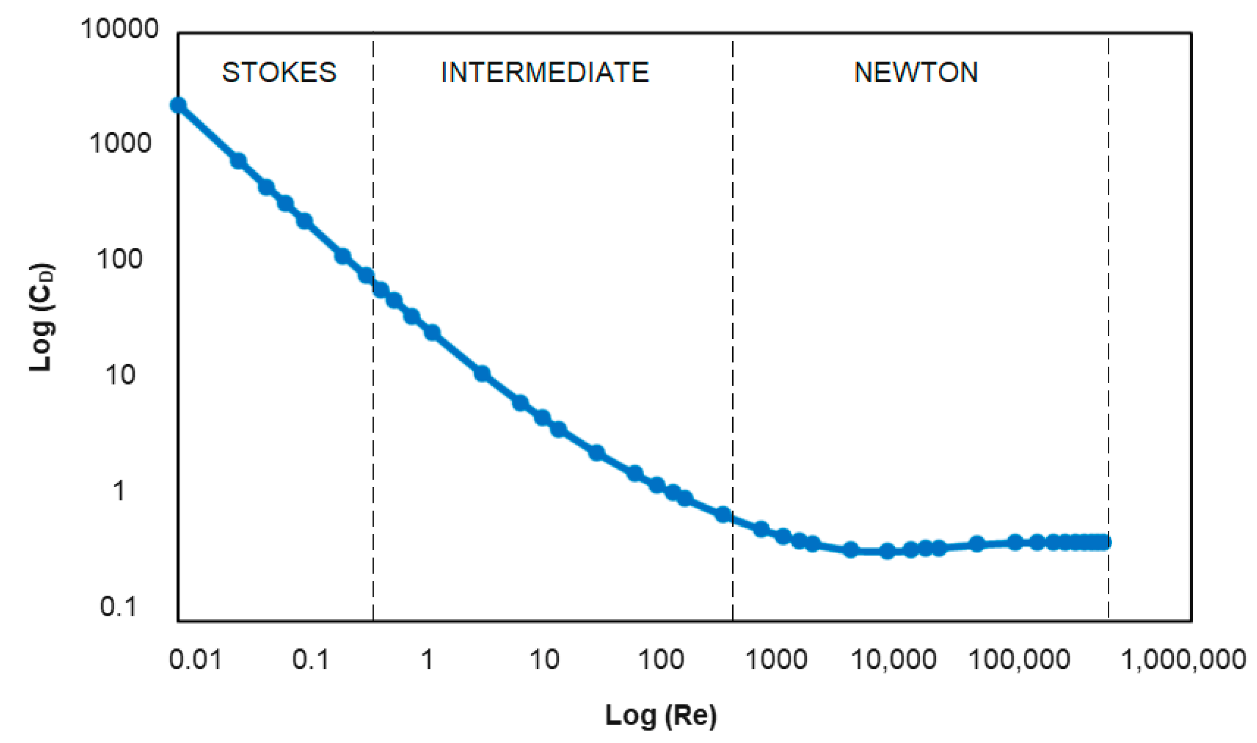
Figure 4.
Typical size range of application of different gravity concentration techniques.
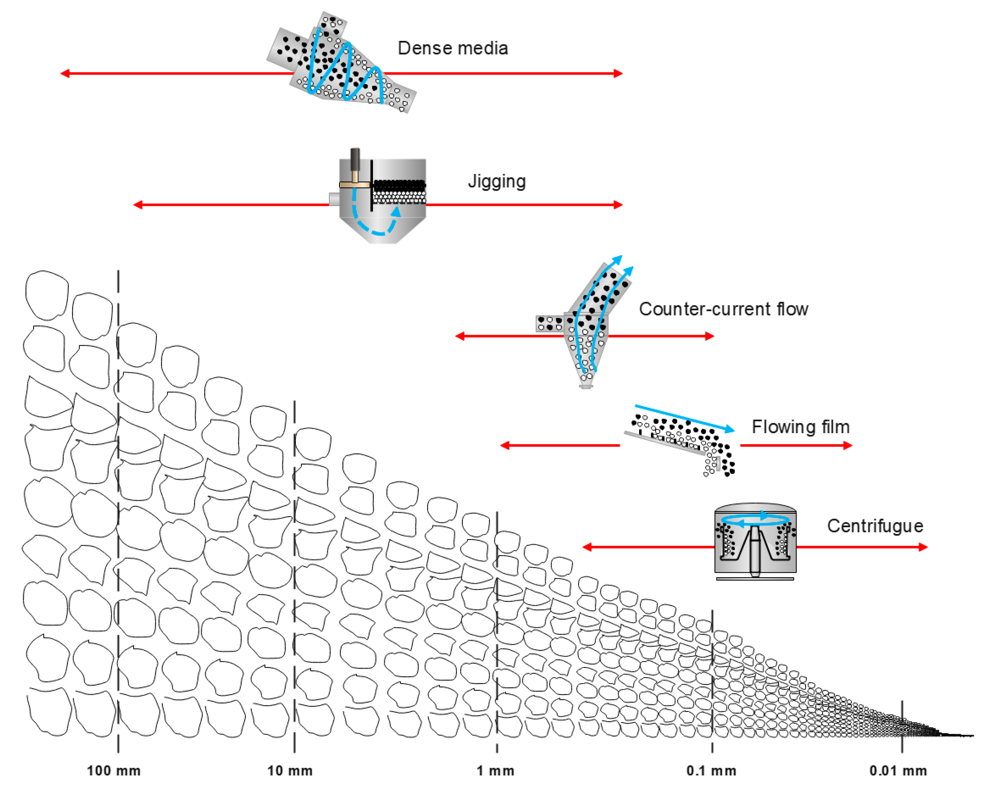
Figure 5.
Scheme of a conventional dense-medium cyclone.

Figure 6.
Terminal velocities of spherical particles of PET and PA in different particle sizes. (a) Terminal velocities in water; (b) Terminal velocities in air.
Figure 6.
Terminal velocities of spherical particles of PET and PA in different particle sizes. (a) Terminal velocities in water; (b) Terminal velocities in air.

Figure 7.
(a) Scheme of a typical hydraulic CCFS separator; (b) Scheme of a ZigZag separator.
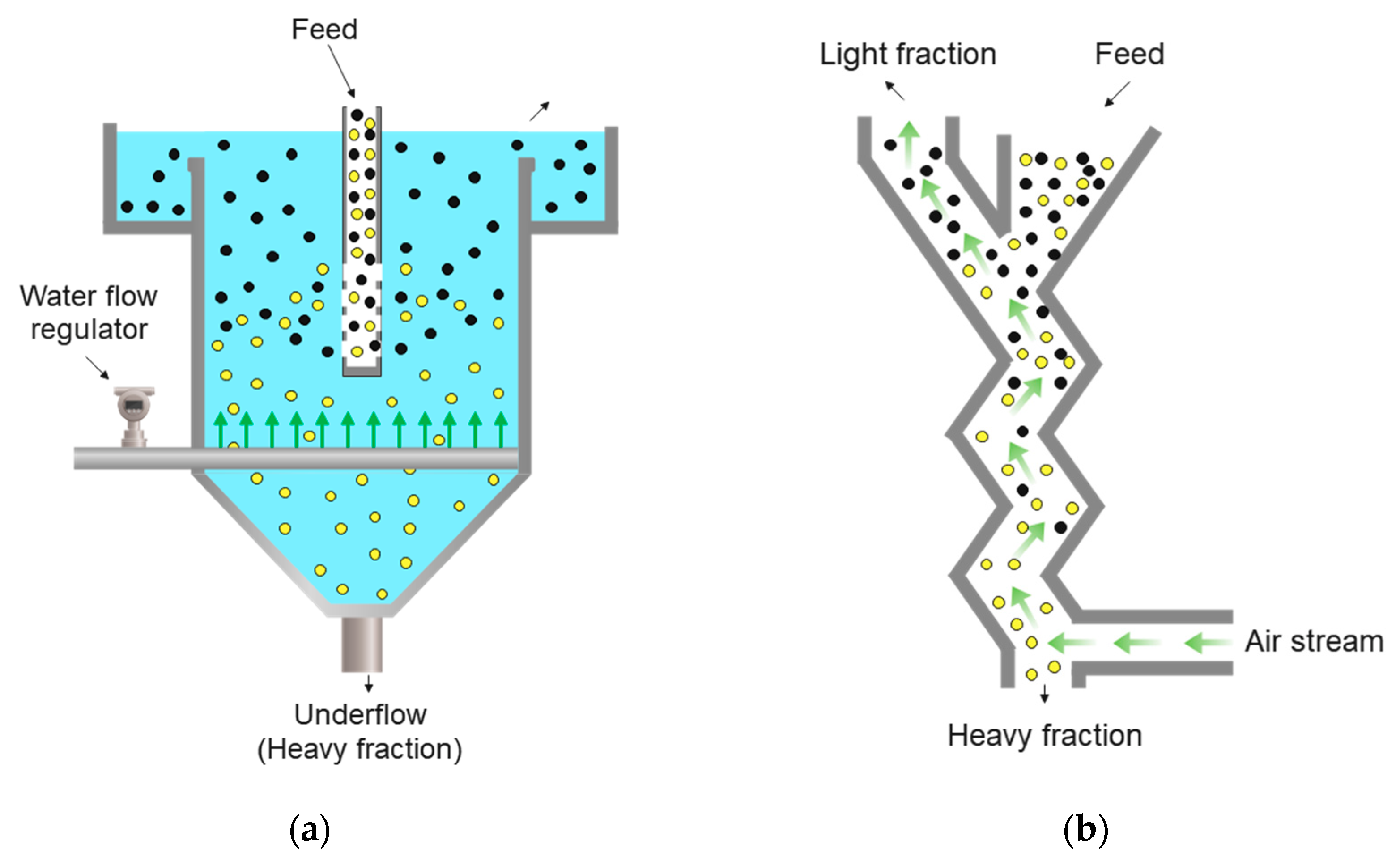
Figure 8.
(a) Scheme of a typical air-pulsed hydraulic jig; (b) Scheme of a dry jigging equipment.

Figure 9.
(a) Scheme of a spiral concentrator; (b) Scheme (top view) of a wet shaking table.
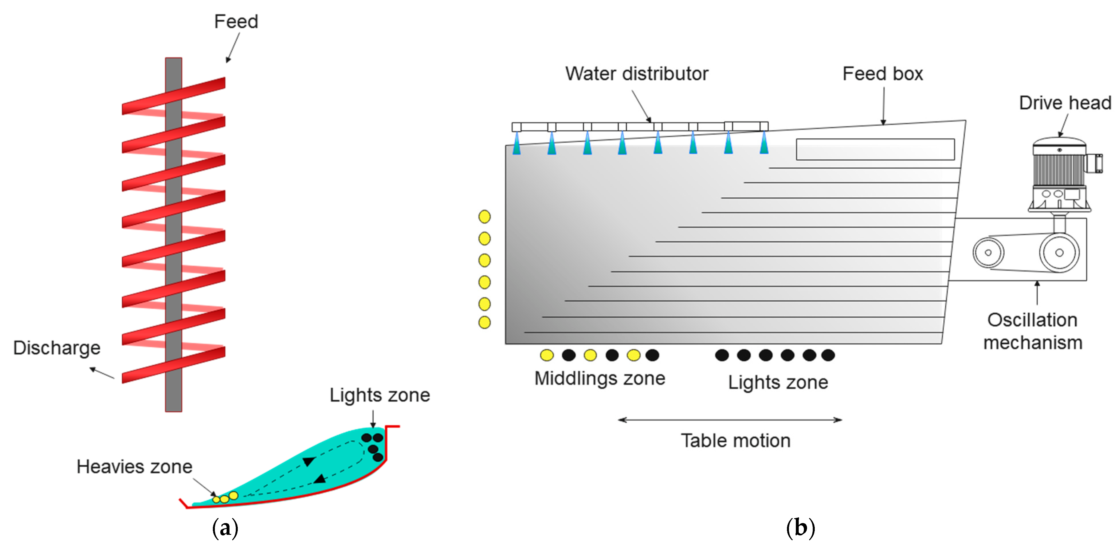
Figure 10.
General scheme of centrifugal gravity separator.

Figure 11.
Gravity separation steps in the separation of mixed solid waste.
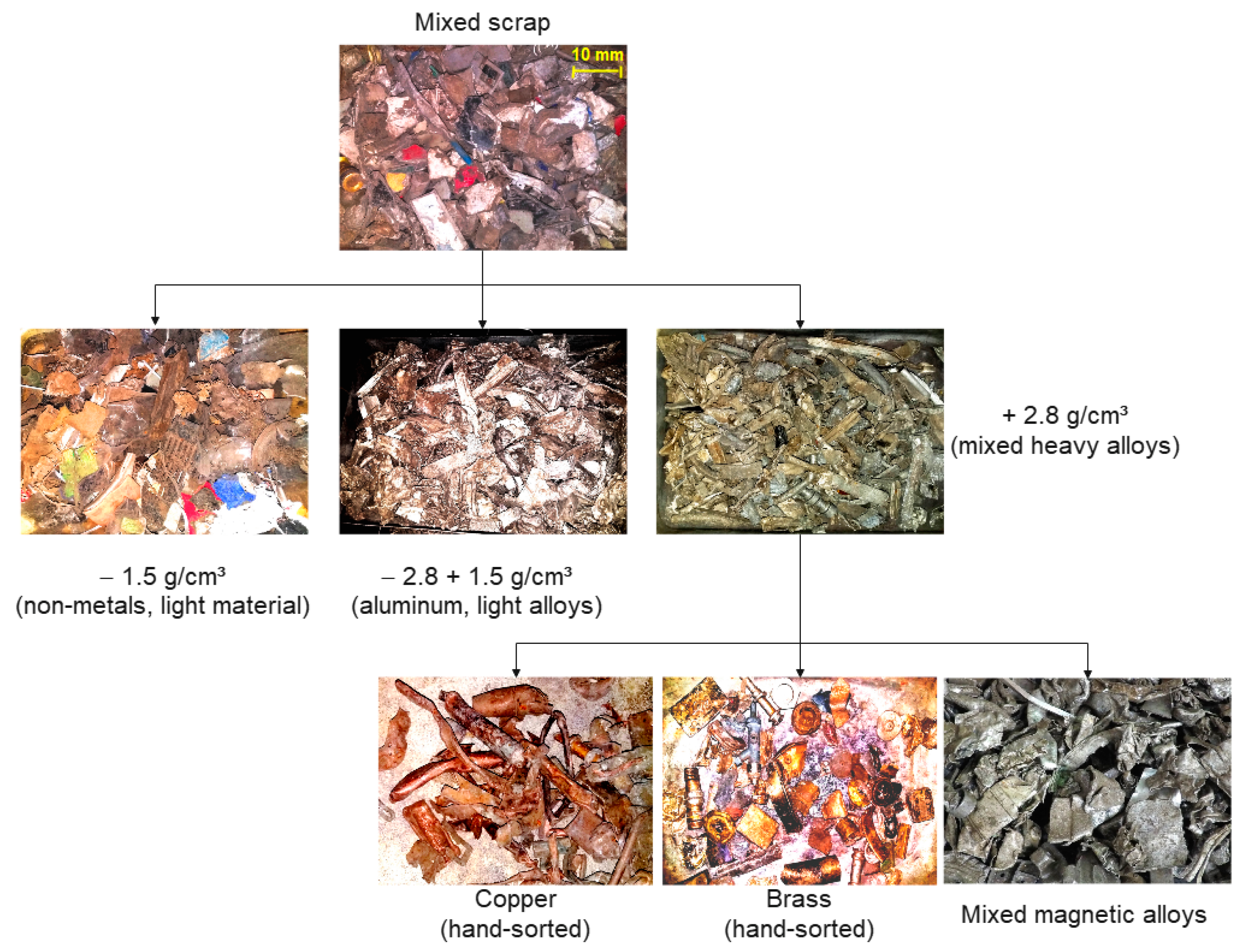
Figure 12.
Separation of wall insulation wastes (polyurethane foam and polypropylene mixtures) in a dry jig.
Figure 12.
Separation of wall insulation wastes (polyurethane foam and polypropylene mixtures) in a dry jig.

Figure 13.
Snapshots of the separation of ternary mixture of gypsum (white), brick (reddish), and concrete (gray) captured by camera positioned at the upper diagonal of a pilot-scale dry jig. (a) Mixed state (before separation); (b) Segregate state (after separation).
Figure 13.
Snapshots of the separation of ternary mixture of gypsum (white), brick (reddish), and concrete (gray) captured by camera positioned at the upper diagonal of a pilot-scale dry jig. (a) Mixed state (before separation); (b) Segregate state (after separation).

Figure 14.
Separation of crushed PCBs (−2 mm) in a Mozley table. (a) Initial mixture; (b) Metallic concentrate on the table surface.
Figure 14.
Separation of crushed PCBs (−2 mm) in a Mozley table. (a) Initial mixture; (b) Metallic concentrate on the table surface.


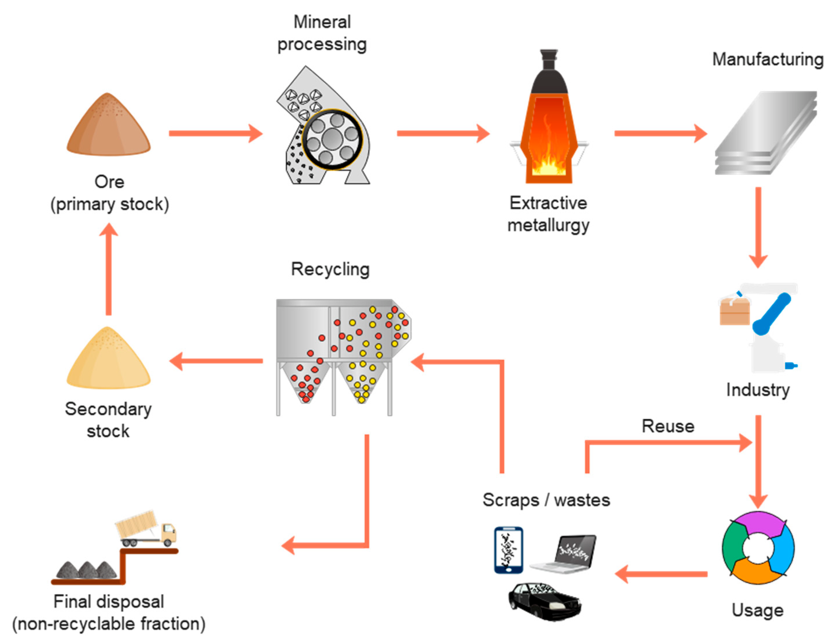
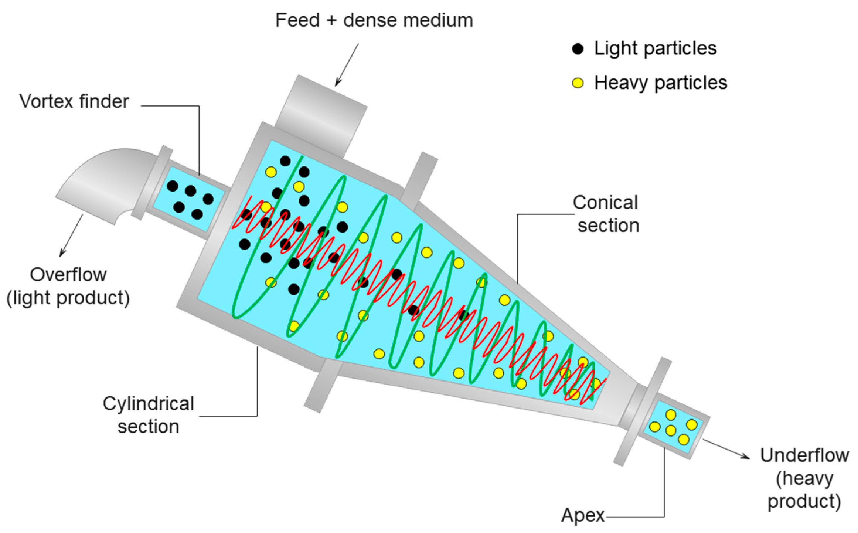
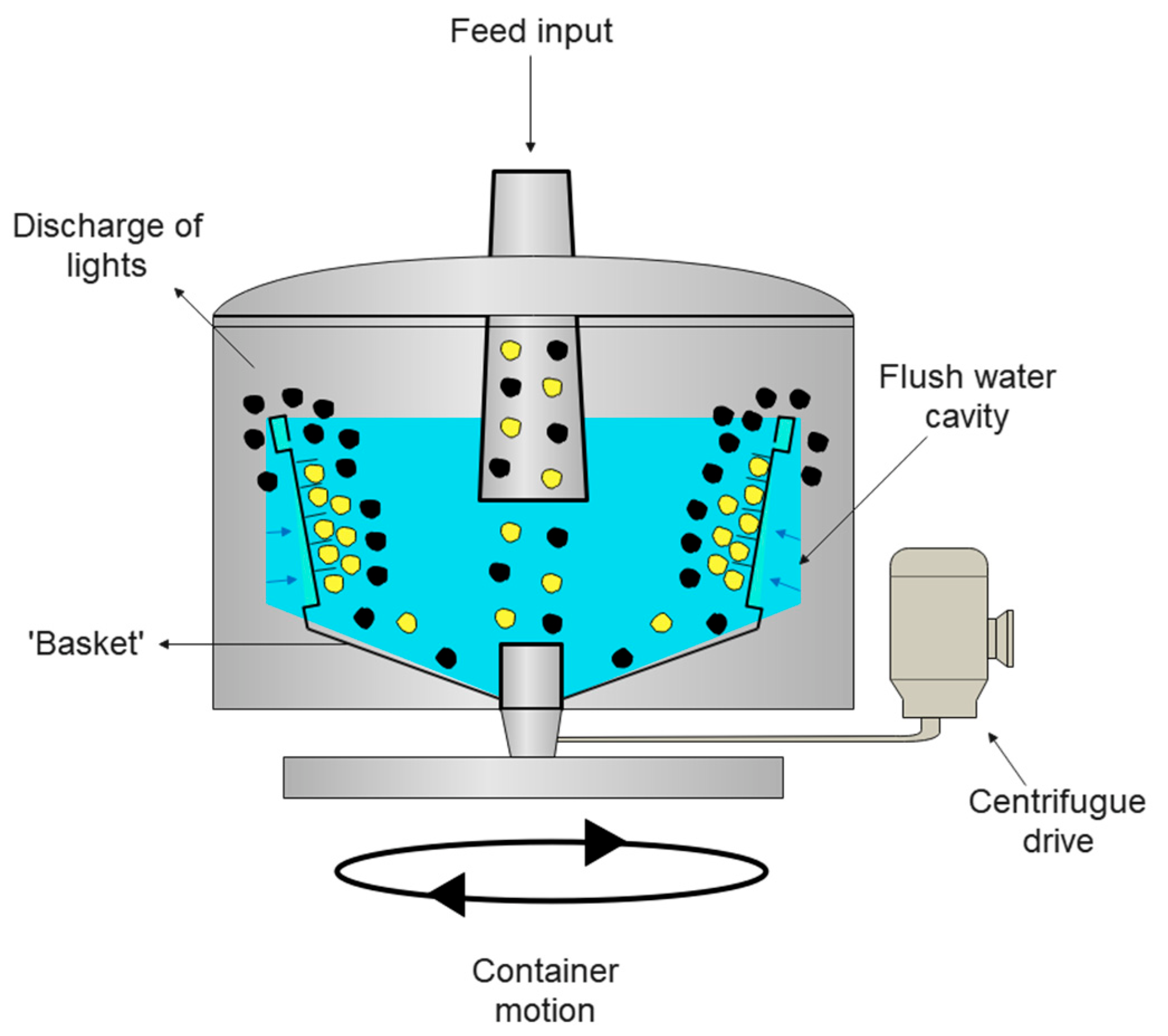
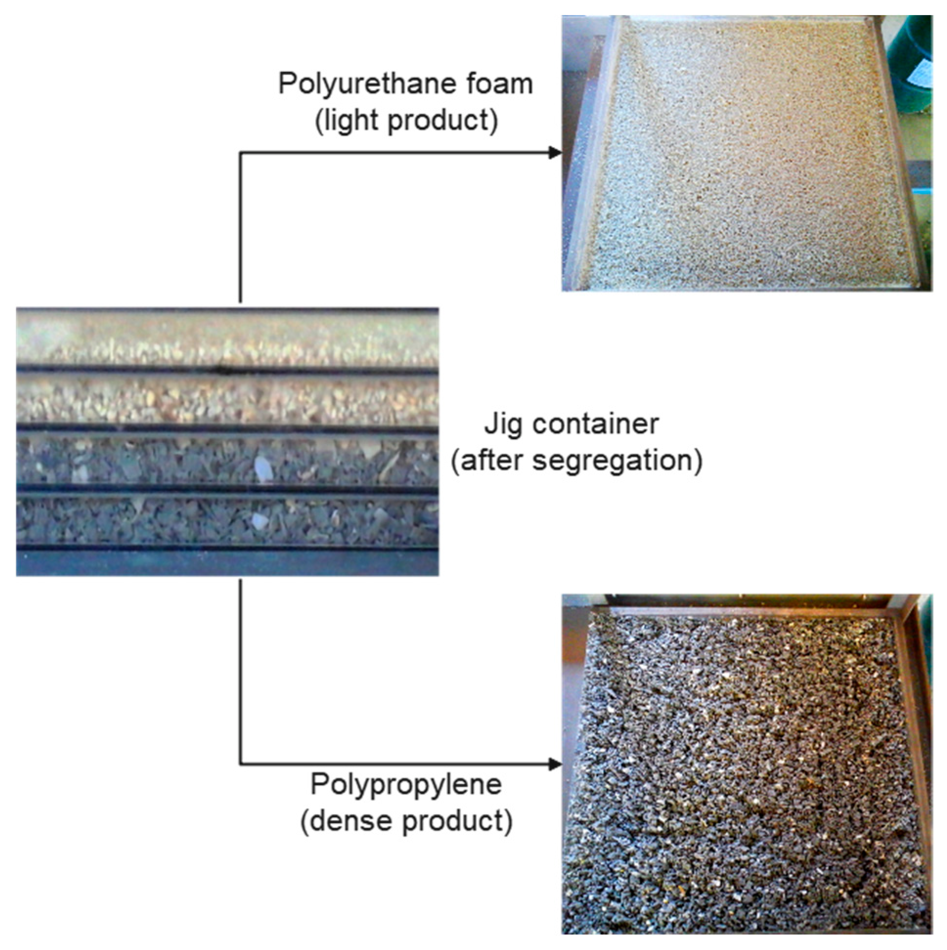
Table 1.
Apparent density of different materials found in solid waste.
| Material | Density (g/cm3) | Reference |
|---|---|---|
| Aluminum | 2.70 | Schlesinger [87] |
| Copper | 8.97 | Schlesinger [87] |
| Lead | 11.30 | Schlesinger [87] |
| Tin | 7.28 | Schlesinger [87] |
| Brass | 8.40 | Schlesinger [87] |
| Stainless Steel | 7.90 | Schlesinger [87] |
| Zinc | 7.14 | Schlesinger [87] |
| Polystyrene (PS) | 1.047 | Pita and Castilho [88] |
| Polymethyl methacrylate (PMMA) | 1.204 | Pita and Castilho [88] |
| Polyvinyl chloride (PVC) | 1.209–1.326 | Pita and Castilho [30] |
| Polyethylene terephthalate (PET) | 1.364–1.372 | Pita and Castilho [30] |
| Ceramic (2 MPa) | 2.22 | Gschwenter et al. [89] |
| Ceramic (7 MPa) | 2.35 | Gschwenter et al. [89] |
| Concrete (16 MPa) | 2.46 | Gschwenter et al. [89] |
| Concrete (54 MPa) | 2.76 | Gschwenter et al. [89] |
| Mortar | 2.04 | Gschwenter et al. [89] |
| Gypsum | 1.86 | Sampaio et al. [90] |
| Fiberboard | 0.60 | Torgal and Ding [91] |
Disclaimer/Publisher’s Note: The statements, opinions and data contained in all publications are solely those of the individual author(s) and contributor(s) and not of MDPI and/or the editor(s). MDPI and/or the editor(s) disclaim responsibility for any injury to people or property resulting from any ideas, methods, instructions or products referred to in the content. |
© 2023 by the author. Licensee MDPI, Basel, Switzerland. This article is an open access article distributed under the terms and conditions of the Creative Commons Attribution (CC BY) license (https://creativecommons.org/licenses/by/4.0/).
Share and Cite
MDPI and ACS Style
Ambrós, W.M. Gravity Concentration in Urban Mining Applications—A Review. Recycling 2023, 8, 85. https://doi.org/10.3390/recycling8060085
AMA Style
Ambrós WM. Gravity Concentration in Urban Mining Applications—A Review. Recycling. 2023; 8(6):85. https://doi.org/10.3390/recycling8060085
Chicago/Turabian StyleAmbrós, Weslei M. 2023. "Gravity Concentration in Urban Mining Applications—A Review" Recycling 8, no. 6: 85. https://doi.org/10.3390/recycling8060085