A Novel Nested Reconfigurable Approach for a Glass Façade Cleaning Robot
by
 ,
,
Shunsuke Nansai
1,* ,
,
Mohan Rajesh Elara
2,
Thein Than Tun
3,
Prabakaran Veerajagadheswar
1 and
Thejus Pathmakumar
1
1
SUTD-JTC I3 Center, Singapore University of Technology and Design, Singapore 487372, Singapore
2
Engineering Product Development Pillar, Singapore University of Technology and Design, Singapore 487372, Singapore
3
SUTD @ Temasek Laboratories, Singapore University of Technology and Design, Singapore 487372, Singapore
*
Author to whom correspondence should be addressed.
Inventions 2017, 2(3), 18; https://doi.org/10.3390/inventions2030018
Submission received: 21 July 2017
/
Revised: 11 August 2017
/
Accepted: 11 August 2017
/
Published: 17 August 2017
(This article belongs to the Special Issue Advances in Mechanism Design for Robots)
Abstract
:The façade cleaning of high rise buildings is one of the hazardous tasks that is performed by human operators. Even after a significant advancement in construction technologies, several newfangled skyscrapers are still using the manual method for cleaning the glass panels. This research is aimed at the development of a glass façade cleaning robot, capable of adapting to any kind of building architecture. A robotic system capable of cleaning vertical glass surfaces demands a transformable morphology. A self-reconfigurable robot is one of the potential solutions to realize high degrees of adaptability. Following the design principles we derived, we propose a nested reconfigurable design approach for glass façade cleaning and develope a system of robot modules that performs glass façade cleaning. Throughout this research article, we discuss the brief concept and scheme of nested reconfigurable design principle and the hardware-software challenges associated with it. This article also discusses the capability to maximize the flexibility and modularity of the robot by using intra- and inter-reconfigurations. The effectiveness of the designed system is verified by experimental means.
1. Introduction
Robots have been advancing exponentially over the last three decades, beyond the traditional bounds of industrial applications, service, and even towards the sharing of social spaces with human beings. The report mentioned in [1] indicates about 47% of the total US employment will be replaced by the robots or any other means of artificial intelligence (AI) in the near future. The work mentioned in [2] points to the improvement of productivity and safety enhancement of numerous hazardous service tasks such as welding, weight lifting, cleaning, etc. Façade cleaning of high-rise buildings and skyscrapers is one among these tasks that requires humans to risk their life and limb. In recent decades, skyscrapers, including the Burj Khalifa [3,4,5,6] in Dubai and Shanghai Tower [7,8,9] in Shanghai, have been known for their cutting-edge construction technologies and processes. Even in the construction and maintenance of such modern skyscrapers, outmoded methods were used for glass façade cleaning and maintenance. In the case of buildings, including the Burj Khalifa, equipment, such as a “gondola”, were not used extensively and humans were employed to clean the façades with the help of hanging guyline ropes. The above mentioned cleaning practice possess high chances of accidents and concomitant casualties, which may result in the loss of life. Numerous accidents have been reported even with the use of a gondola for façade cleaning jobs. For instance, the sudden blow of storm at Shanghai World Financial Center [10] resulted in the loss of control of gondola. In another example, the gondola got suspended at a height of 240 m during the maintenance of the World Trade Center in New York city [11]. The involvement of robots in scenarios like glass façade cleaning can potentially minimize the risk of accidents and maximize the productivity.
We have identified plenty of research works on the robot involved solution for the façad cleaning, which have sprouted up in a decade. A series of sky-cleaners that are driven by pneumatic actuators for the concurrent locomotion and cleaning of a glass wall by using the vacuum suction cups are discussed in [12,13]. The works mentioned above explore sky-cleaners with suction cups on the both ends of actuators in the X–Y stage and suction cups attached to a vacuum pump [14]. Serbot AG, an industrial company in Switzerland, has developed a wall—solar panel cleaning robot named GEKKO [15]. GEKKO is equipped with a vacuum suction cup based crawler that can rotate horizontally. The crawler has a semicircular structure with a straight line on one side and an arc line on the other, which helps to achieve both linear and rotational motions. By varying the number of brushes and the crawlers, the robot can be manually reconfigured to make itself adaptable to various wall areas. Seo et al. has developed ROPE RIDE [16], which can climb vertical surfaces by utilizing a rope dropped down from the top of the building. The ROPE RIDE is installed with two additional propeller thrusters to ensure a strong attachment to the wall. A new wall cleaning unit using an impedance control system is proposed in the work mentioned in [17]. As an extended work, authors also experimentally demonstrated the effectiveness of the force control system to press the brushes into the wall by exerting a constant force [18]. Furthermore, Fraunhofer IFF, a research institute, developed a wall cleaning robot named SIRIUS [19,20,21,22]. The SIRIUS robot is capable of performing an up-and-down motion on a vertical surface, using a crane installed on buildings for façade maintenance. The robot adheres to the wall by the suction system and moves with the help of linear actuators [23,24,25]. Even though the existing robot-aided solutions for façade cleaning each excel in their effectiveness and experimental results, the performance of the current robots are constrained to their target buildings. Precisely, the robots require additional equipment such as a crane, i.e., the system is still requires significant development to adapt to various building architecture. Hence, adaptability is a factor that lacks in the present façade cleaning scenario. In this research article, we present the development of a highly modular glass façade cleaning robot. The robotic cleaning system introduced in this work, that operates independently on the building structure demands a system with variable morphology. A self-reconfigurable robot is one of the potential solutions to realize alternation of morphology and maximize the adaptability. Our previous works prove that nested reconfigurable robots possess higher versatility than the typical self-reconfigurable robots [26,27,28]. Hence we are exploiting a nested reconfigurable design concept for the development of a wall climbing robot system for glass façade cleaning.
Our previous works [26,27,28] covers a brief concept and scheme of the nested reconfigurable design principle we used for the development of the proposed robot. The nested reconfigurable system is capable of maximizing the flexibility and the modularity corresponding to various environments or tasks with different types of intra- and inter-reconfigurable modes. Moreover, this paper covers the solutions for the development of the wall climbing robot for cleaning of high rise buildings based on the nested reconfigurable design principles. Besides, the hardware and software designs challenges involved in the implementation of the nested reconfigurable design principle are also included. We have conducted real time experiments to analyze the movement of the developed robot platform on a typical rectangular glass window, and analyzed the locomotion and the ability to adhere to the glass surface. The rest of the paper is organized as follows: Section 2 summarizes the concept and scheme of the nested reconfigurable design principle and specific hardware/software design challenges are proposed. Section 3 develops the platform. A system architecture for the platform is reported in Section 4. Section 5 concludes this paper.
2. Nested Reconfigurable Design Challenges for a Glass Façade Cleaning Robot
Generally, the implementation of nested reconfigurable design principles on robotics opens up the scope for achieving numerous tasks that are difficult to achieve using a fixed morphology robot. In the case of glass façade cleaning, the robot design must satisfy the two factors we mentioned below.
- terrain adaptability:
- -
- adaptability to window shapes
- -
- ability to avoid obstacles (window frames)
- cleaning ability:
- -
- effective cleaning mechanisms
- -
- effective cleaning strategy
The execution of cleaning tasks varies according to several external factors associated with the surfaces to be cleaned. For example, the cleaning of a dry glass surface requires the execution of washing. Whereas, the cleaning of a wet glass surface doesn’t require the washing process to be done. Similarly, brushing must be executed to clean the walls of buildings near desert regions because brushing is essential to remove the sand particles trapped inside the crevices of glass windows. Hence, the robot has to be designed in such a manner that it should be able to traverse and clean any building irrespective of its architecture. “Terrain adaptability” refers to the locomotion capability of the robot on glass frames having different shapes. Typically, the glass panels can be observed in five different shapes including horizontally long, vertically long, parallelogram, trapezoidal, and curvilinear, as shown in Figure 1. Moreover, the shape of the glass panels can be a combination of these five shapes to form a complex shape such as a horizontally-long-parallelogram, vertically-long-trapezoidal, etc. Hence, the robot must adapt to the glass panel having a complex geometry to execute a locomotion independent of the architecture of a building. Even though there exist glass panels with numerous shapes, all of them can be categorized into two. From the close observation on the geometry of various glass panels, we can infer that the window size and the window shape are the two key parameters that characterize all the glass panels. In this context, we define the window size as ratio of horizontal and vertical dimensions of the glass window to be cleaned. The horizontally-long-parallelogram and vertically-long-parallelogram are different descriptions belonging to the same category: the parallelogram. Hence the robot design should be capable of adapting to different window size and window shape to achieve the terrain adaptability factor.
Cleaning ability, the second factor to be considered for the design of the proposed system refers to the identification of the best method to achieve effective cleaning. To identify the efficient cleaning mechanism for the robot, we observed the way of glass façade cleaning done by experts. For manual cleaning, the scrubber and squeegee are the primary tools used by experts. The experts clean glass walls by approaching the glass surface to be cleaned, washing the dirt off by using the scrubber and cleaning liquid, and finally wipe the dust residue using a squeegee (see Figure 2). We identified that to ensure an effective cleaning, experts clean the window from top to bottom and ensure the movement of the squeegee such that it traces the surface covered by the scrubber. Besides, they ensure the complete contact of the squeegee over the glass surface during cleaning and cleaning is done towards a single direction (see Figure 2 (b)→(c)→(d)).
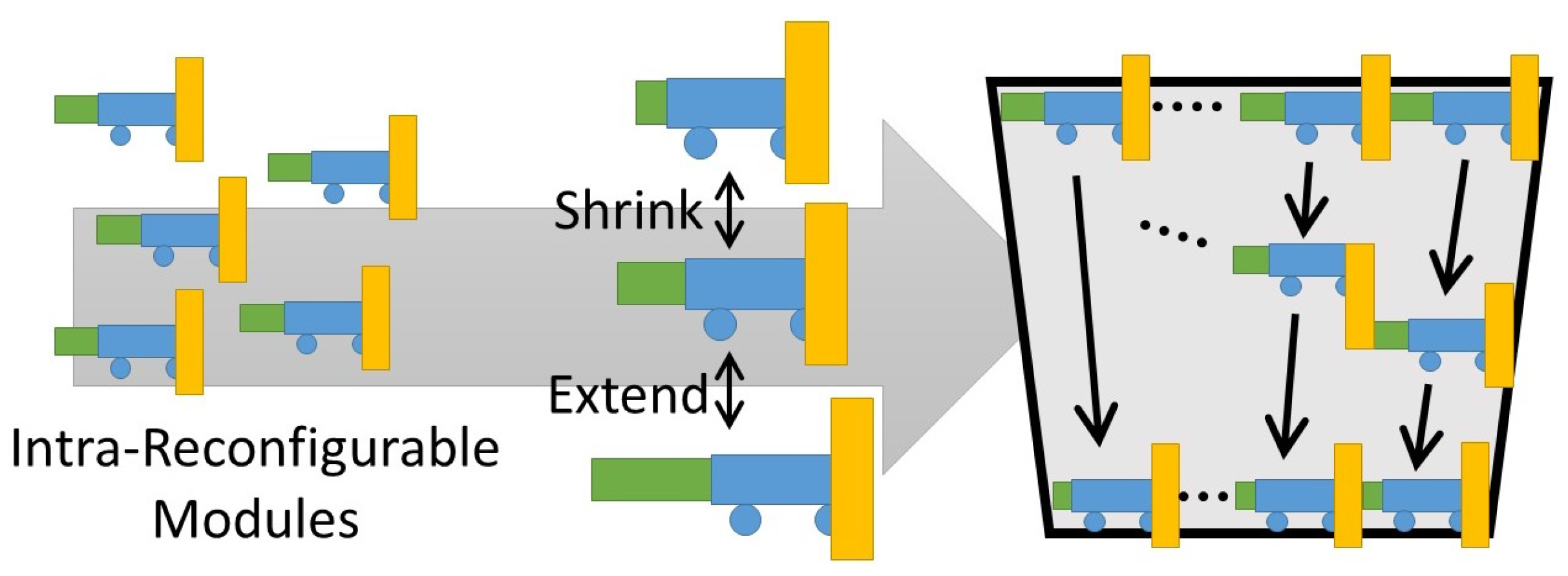
The strategy we adopt to realize both terrain adaptability and cleaning ability is the usage of multi-layer reconfigurability. Figure 3 shows a solution for window size and window shape adaptation that belongs to the factor “terrain adaptability”. Using a fixed number of robot modules, the extension and contraction of individual modules helps the robot system to adapt to various window shapes. For instance, if the window shape is trapezoidal, the extension and contraction of individual modules helps the system to traverse from the broader end to narrower end. On the other hand, a different trapezoidal glass window with a larger size can be cleaned by increasing the number of modules of the same kind and vice versa. The solution we identified is a modular system that consists of both intra- and inter-reconfigurability in hardware. The robot design is individually extendible (intra-reconfigurable) and is capable of conjugating with other modules (inter-reconfigurable). The intra-reconfiguration of each module helps the robot to adapt to various window shapes. Similarly, the system becomes adaptable to window size by varying the number of robot modules to be deployed. Figure 4 shows the identified cleaning mechanism and cleaning strategy for achieving cleaning ability. The cleaning ability can be accomplished by inter-reconfiguration of multiple modules. For instance, a two-robot system equipped with a squeegee next to the scrubber can execute the cleaning of the window from top to bottom. The scrubber can trace the movement of the squeegee and it can clean toward the one direction as well. The challenges of the hardware and software parts of the proposed robot system are listed below:
- hardware design challenges
- -
- development of the extendible module (intra-reconfigurable module).
- -
- development of module assembling system.
- -
- development of cleaning unit with squeegee next to the scrubber.
- software design challenges
- -
- design of control system capable of keeping both the scrubber and the squeegee touching to the glass surface.
- -
- design of transition planner to achieve cleaning toward to one direction.
3. Mechanical Design
The design challenges for the glass façade cleaning robot is discussed in Section 2. In this section, we discuss the hardware design of the robot system. We formulated the mechanical design of the proposed robot modules based on the nested reconfiguration principles and identified hardware design challenges. Figure 5 shows the CAD design of the developed module. The designed module consists of three linear actuators, to enable actuation on X, Y, and Z directions. The strong attachment to the glass surface is achieved using suction cups. Moreover, the cleaning unit is mounted on the linear actuator such that the unit can move in horizontal directions. This arrangement helps the robot to re-configure its length by itself (inter-reconfiguration) by performing the extension.
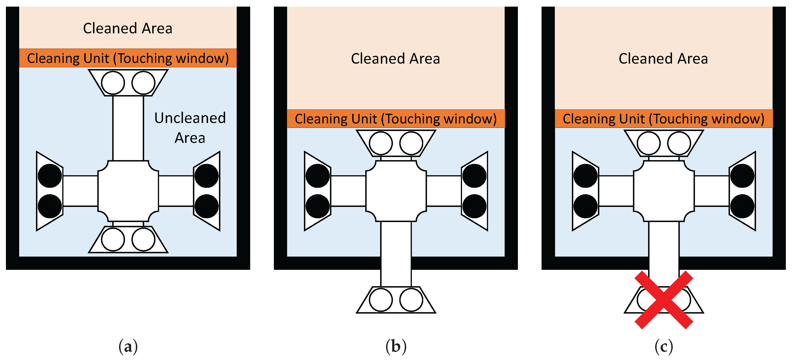
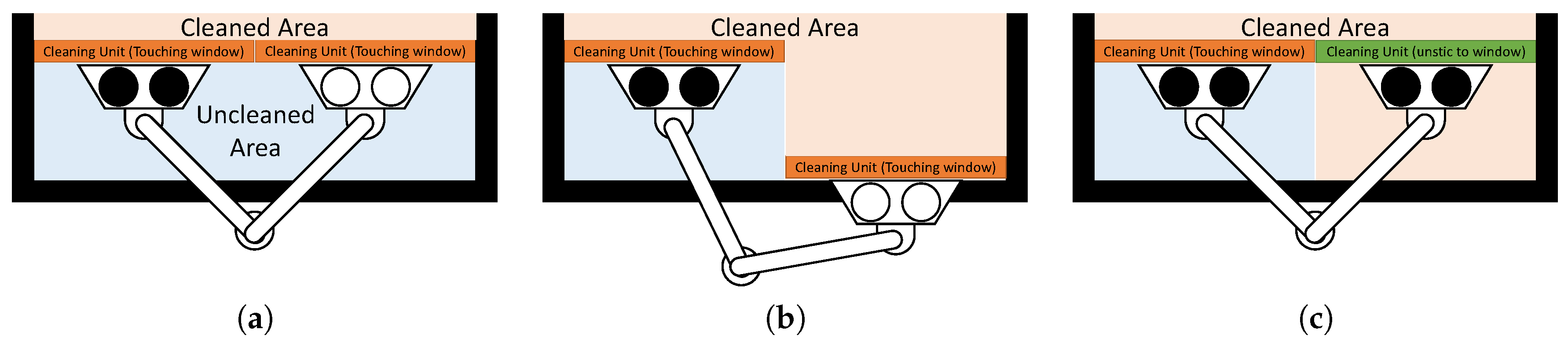
The three actuators perform three different tasks. The actuator on the horizontal directions helps to achieve the extension action, whereas the actuator in the normal direction helps to avoid the obstacles (the window frames that projects out from the glass surface) and traverse through the wall. The actuator in the vertical direction does the attachment of a nearby module. There are two common methods for achieving wall climbing. One is the legged type method as in the sky cleaners mentioned in [12,13], the robot proposed by Yano et al. [29,30], and by Kawasaki et al. [31]. Another method for wall climbing is the wheel/crawler-type, as in the works presented by Gao et al. [32,33], Miyake et al. [34,35], and Kim et al. [36,37]. The robots that belong to the legged-type family have discontinuous contact points on the glass surface and are controllable within the range of operation of the robot. However, a leg of the robot (a part of the negative pressure generating area) has to leave the surface of contact to achieve movement. Hence, the suction mechanism of the robot has to generate a large scale negative pressure during every locomotion. On the other hand, wheeled or crawler-type robots have continuous contact points on the glass surface. Unlike the legged type robots, wheeled type robots could generate adhesion force uniformly on the surface of contact during movement. In a glass cleaning scenario, it is necessary to overcome obstacles such as the window frames and protrusions on the glass surfaces to perform an efficient transition from one glass panel to the other. Comparing with wheeled robots, a pragmatically better robot design to achieve obstacle avoidance is the legged variant. Furthermore, wheeled/crawler-type robot design can be further subdivided into an X–Y stage design and a biped-type. As we discussed in the design challenges mentioned in the second section, the module has to move the cleaning unit from the top of the window to the bottom continuously to achieve effective cleaning. In the case of an X–Y stage legged robot, it is hard to realize complete area coverage due to its design limitations. Figure 6 explains the of locomotion of the X–Y stage legged type robots in the particular context in which the robot fails to accomplish complete area coverage. On the other hand, the same motion can be achieved in a biped design with the help of an enhanced control strategy (Figure 7). Hence, we choose the characteristics of the biped-type robot for the proposed design. We developed the robot module such that all modules are equipped with a biped mechanism and the ith module always conjugates with the module. Another characteristic of the proposed design is the individual controllability of the scrubber and squeegee in the cleaning unit because both scrubber and squeegee are required to move from the top of the window frame to the bottom.
The CAD diagram of fabricated robot modules is shown in Figure 8. For the linear actuators in both normal and vertical direction, we adopted the ladder chain and sprocket mechanism. We used a DC motor (131:1 Metal Gearmotor 37 D × 73 L mm with 64 CPR Encoder, 18 kgf·cm of maximum torque, 80 rpm free-run, product by Pololu) equipped for generating the driving force for the actuators. Since the maximum torque from the DC motor is 18 kgf·cm, the maximum attainable force is 14.63 kgf. Since the maximum rotational speed of the DC motor is 80 rpm, the maximum feed speed is 0.10 m/s. The structural weight of the module to be fabricated is 5.423 kg including battery and all peripherals. For the calculations we took the weight of the module as 6 kg, considering the safety of the prototype and envisioning the fabrication of a real robot that is a prototype. The factor of safety we maintained is 2.98. Regarding the linear actuator in the normal direction, we calculated the displacement [cm] by performing the calculations as mentioned below:
Let the angle of rotation of the motor be [rad] and the displacement is [cm],
where [cm] represents the radius of the sprocket associated with the ladder chain system. We chose cm for this module. Similarly, for the linear actuator in the vertical direction, a sprocket and chain ladder mechanism that can create a movement towards both sides of the ladder chain is used. Let the angle of rotation of the motor be [rad], then the relative distance between each stage [cm] is calculated as follows:
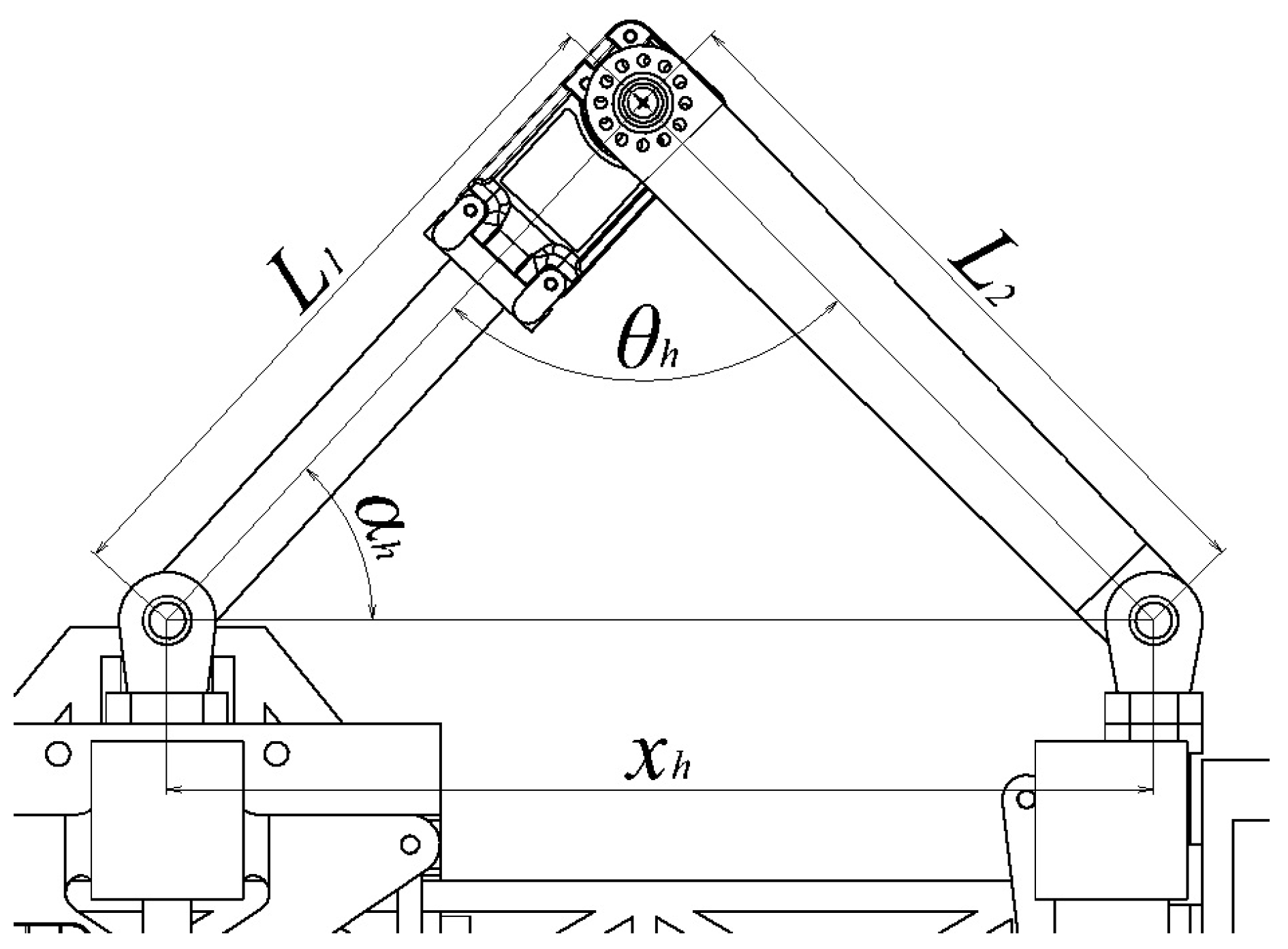
For the linear actuator in the horizontal direction, we used the slider-crank mechanism. The servo motor (HerkuleX DRS-0101, 12 kgf·cm of stall torque, 0.166 s/60 deg of maximum speed) is used as the driving force generator for the linear actuators. Let the angle of rotation of the motor and the length of each link be [rad], , and (as shown in Figure 9). From the law of cosines, the length of extension is calculated as:
In addition, let an angle between [cm] and [cm] be [rad], and the length from [cm] to the motor axis be [cm]. The maximum force required for the extension action [kgf] is formulated as follows:
Note that the force in the horizontal direction is not used to support the weight of the module unless it takes an inclined configuration.
The module equips four suction cups of 10 cm diameter each, as the suction cups are used by experts for safety purpose and possess fewer chances for air leakage but are easy to release vacuum, using the pin mechanism associated with it (Figure 10).
We automated the pulling action on the pin to release the vacuum inside the suction cup. We engaged the pin with the servo motor using a light metal chain. The tensile force generated in the chain during the rotation of servo motors does the automatic pulling of the pin associated with the suction cups. We used Herkulex DRS-0101 servo motors (manufacture: DST Robot ,Jiksan-eup, Korea) to achieve the task mentioned above. In general, the adsorption force of a suction cup W [N] is
where, C [cm], P [−kPa], and f represent the area, vacuum pressure, and safety factor of the suction cup, respectively. Since four suction cups with 10 cm diameter each are equipped in the module, × × cm and the safety factor is set as 1/8 based on the standard value used for vertical lifting cases. Figure 11 shows the linear variation between the required vacuum pressure to the adsorption force.
From Figure 11 and (1), the required vacuum pressures to hold the modules one, two, and three are −14.99, −28.98, and −44.97 kPa, respectively. Since a passive suction cup (without any vacuum generator) is utilised in this module, the vacuum pressure occurs due to the variation of volume inside the suction cup, assumed as a circular cone in our calculations. The pressure inside the chamber after pushing the suction cup equals the external air pressure, assumed to be atmospheric pressure. When the suction cup is restored to its original state, when we release the pushing force, the vacuum pressure is generated. If the vacuum pressure thus generated is greater than the requirement, the suction cup can adhere to the glass surface. Let [cm] be the volume of the suction cup after releasing the pushing force. We deduce the condition for the module to attach on the glass surface using following calculations:
Using Boyles’ Law:
where, [kPa] and [kPa] are the atmospheric pressure and the required vacuum pressure, respectively, and [cm] is the volume of the chamber inside the suction cup before pushing it (i.e., the default state of suction cups). Hence, the required variation in volume [cm] required to attach the module to the glass surface is
The diameter of the equipped suction cup is cm and the height of the chamber in its default state cm. The chamber height after the pushing action is [cm], thus
Hence, the pushing depth [cm] required to adhere the module to the glass surface is
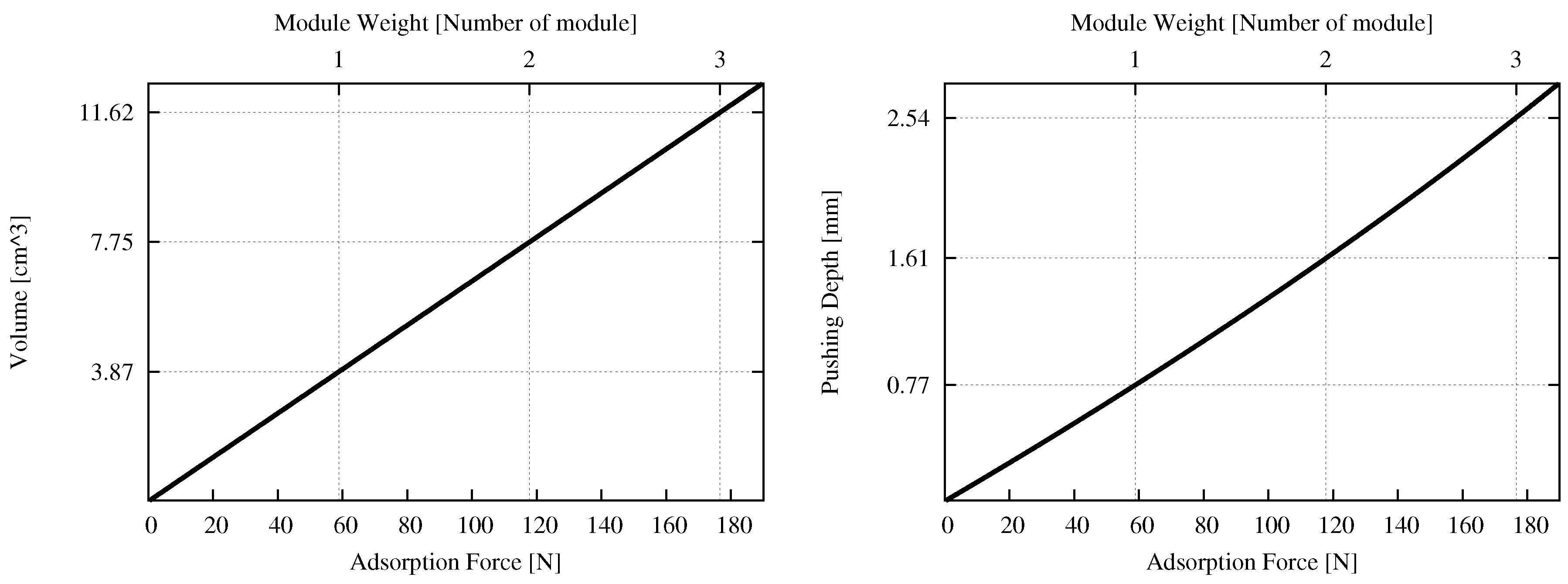
Figure 12 shows the required volume variation and the required variation in pushing depth corresponding to the adsorption force. From Figure 12 (Left) and (2), the required volume variation to hold one, two, or three modules is 3.87, 7.75, and 11.62 cm, respectively. From Figure 12 (Right) and (3), the required pushing depth to hold one, two, or three modules is 0.77, 1.61, and 2.54 mm, respectively.
4. System Architecture
In this section, we discuss the underlying system architecture for controlling the proposed nested reconfigurable façade cleaning robot system consisting of two modules. Figure 13 shows the diagram of the implemented system architecture. Both of the modules are equipped with a Arduino MEGA 2560 microcontroller to control the actuators and running the foremost control program. The communication between the robot system and the operator is established in a wireless fashion using Bluetooth. We interfaced a DF-Robot Bluetooth V3 module (Bluetooth chip: CSR BC417143, Bluetooth protocol: Bluetooth Specification v2.0 + EDR) with the microcontroller to establish communication between the main controller and the user end Bluetooth device. The Pololu Dual VNH5019 Motor Driver Shield for Arduino is used for driving the DC motors. Lithium ion batteries of 11.4 V and 7.4 V are used for supplying the working voltages for the microcontroller and DC motors, respectively. The DC motors and the servo motors are controlled by a proportional-integral (PI) servo controller by taking angle information sent from the microcontrollers as the input command. One of the features of the proposed system is that the servo motors associated with the system are not driven directly by commands sent from the operator. Instead, the microcontroller receives the action to be performed by the robot from the user end as simple commands and generates the direction profile for all servo motors and DC motors. The rotation profile for each motor is updated in a closed control loop, whenever the microcontroller receives a command from the user. The above mentioned control method allows the user to control the robot without concerning any disturbances created by gravity and other external factors that affect the proper control of the robot system. The update of the trajectory and the rotation profile for the motors are generated by the microcontroller based on the type of command received from the user and number of times the command is received. Hence, the operator can operate the system instinctively by pressing and holding the button in a graphical user interface application in a smartphone or a tablet that has the Bluetooth connectivity. Besides, the trajectory update is limited to the working volume of the mechanical design and calculations from sensor values of the servo motors and rotary encoders of the DC motor.
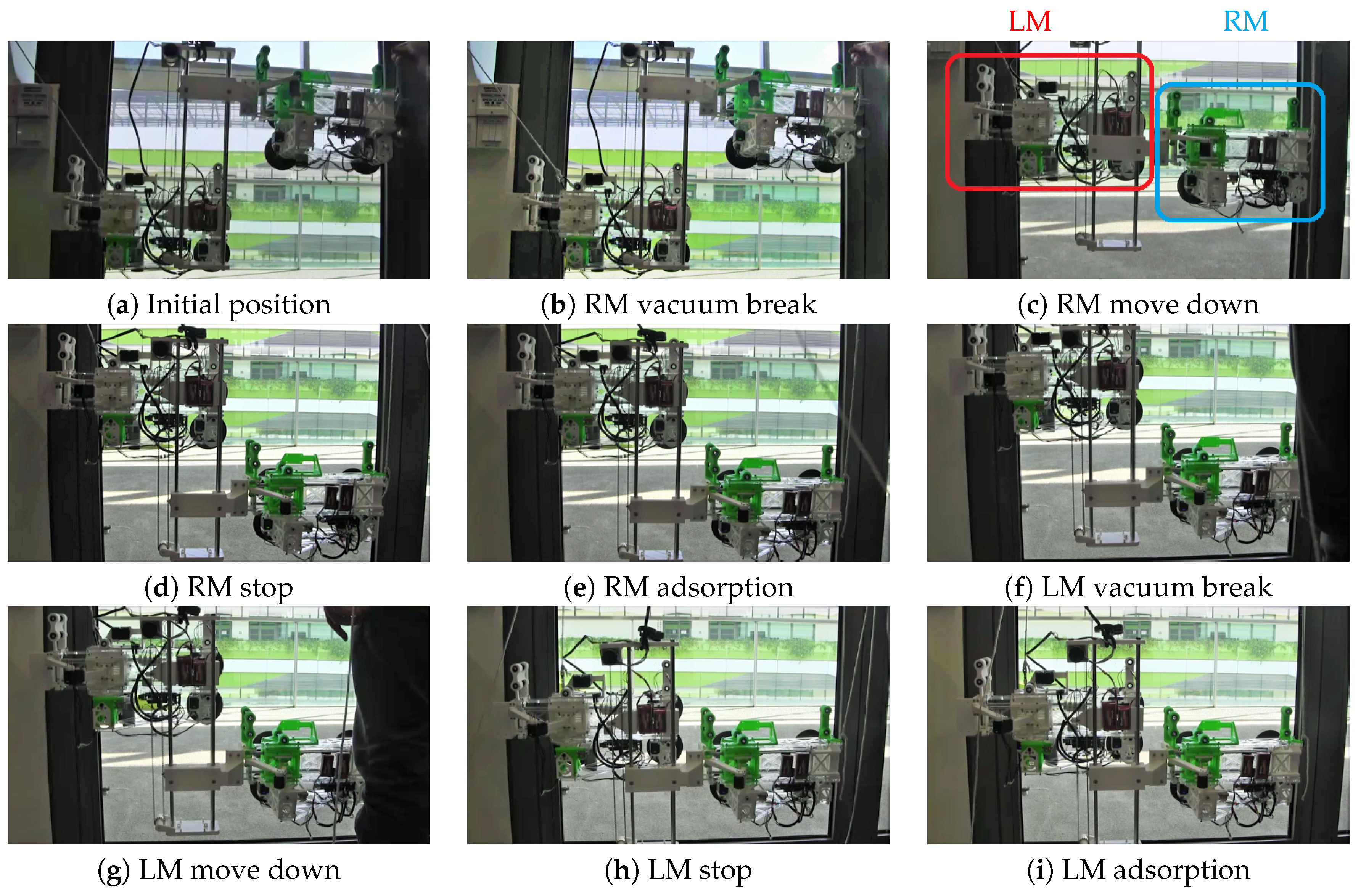
We performed real-time experiments to test the locomotion capabilities of the nested reconfigurable façade cleaning robot system. Since the experiment has to validate the locomotion capability of the robot and its ability to stick on to the glass surface, we chose a typical rectangular glass window. The experiment is performed in a laboratory room with safety ropes attached to prevent accidents. We observed that the developed modules can move on the vertical glass surface. We could also infer that, even if the attachment between a single suction cup and the glass wall is not properly established, the still platform is capable of being held by another module. Parameters of the PI servo control system for the DC motors are set as P gain = 0.1 and I gain = 0.0001. Figure 14 shows the images captured during the experiments.
5. Conclusions
In this research work, we identified the nested reconfigurable design principle for a glass façade cleaning robot and we developed two module robot system as a primary footstep towards the effective realization of the nested reconfigurable façade cleaning robot. We formulated the concept and the scheme of the nested reconfigurable design principle and identified two major factors (terrain adaptability and cleaning ability) that play a significant role in the design of the robot system for glass façade cleaning of high rise buildings. We addressed the hardware and software challenges in implementing reconfigurability in different layers and successfully designed a robot module with a nested reconfigurable design.
We developed the intra-reconfigurable module based on the design challenges and realized the most basic platform of the nested reconfigurable façade cleaning robot consisting of the two modules as well. We conducted experiments to analyze the adhering capability and locomotion of the module on a typical glass window of rectangular shape. It has verified that the developed modules and the designed system can move on the vertical glass surface by experimental means. However, we identified factors regarding locomotion reliability that have to be improved. One is the stability of the suction cups. To adhere the suction cups to the glass surface, it is necessary to apply pushing force equally distributed against the glass surface. Since the module adheres to the glass surface only by utilizing a pushing force applied on the suction cups, there are high chances for deformation and slippage of the suction cup. Thus, the suction cups are attached to the glass surface improperly. As our future works, we will address the issue mentioned above by modifying the mechanical design and synchronizing the action of servo motors to generate a uniform pushing force.
Acknowledgments
This research is supported by the SUTD-JTC Industrial Infrastructure Innovation Center under grants IPJTCT 31501.
Author Contributions
Shunsuke Nansai and Mohan Rajesh Elara conceived and designed the experiments; Shunsuke Nansai, Mohan Rajesh Elara and Thein Than Tun performed the experiments; Shunsuke Nansai, Prabakaran Veerajagadheswar and Thejus Pathmakumar analyzed the data; Thein Than Tun, Thejus Pathmakumar, and Prabakaran Veerajagadheswar contributed reagents/materials/analysis tools; Shunsuke Nansai, Mohan Rajesh Elara, Thejus Pathmakumar, Thein Than Tun and Prabakaran Veerajagadheswar wrote the paper.
Conflicts of Interest
The authors declare no conflict of interest.
References
- Frey, C.B.; Osborne, M.A. The future of employment: How susceptible are jobs to computerisation. Technol. Forecast. Soc. Chang. 2017, 114, 254–280. [Google Scholar] [CrossRef]
- International Federation of Robotics. Service Robot Statistics. Available online: http://www.ifr.org/service-robots/statistics/ (accessed on 16 August 2017).
- Aldred, J. Burj Khalifa—A new high for high-performance concrete. In Proceedings of the Institution of Civil Engineers-Civil Engineering; Thomas Telford Ltd.: London, UK, 2010; Volume 163, pp. 66–73. [Google Scholar]
- Baker, W.F. The World’s tallest. Structure Magazine, June 2011; 51. [Google Scholar]
- Baker, W.F.; Korista, D.S.; Novak, L.C. Burj Dubai: Engineering the world’s tallest building. Struct. Des. Tall Spec. Build. 2007, 16, 361–375. [Google Scholar] [CrossRef]
- Weismantle, P.A.; Smith, G.L.; Sheriff, M. Burj Dubai: An architectural technical design case study. Struct. Des. Tall Spec. Build. 2007, 16, 335–360. [Google Scholar] [CrossRef]
- Zeljic, A.S. Shanghai Tower Façade Design Process. International Conference of Building Envelope Systems. 2010. Available online: http://www.gensler.com/uploads/documents/Shanghai_Tower_Facade_Design_Process_11_10_2011.pdf (accessed on 16 August 2017).
- Xia, J.; Poon, D.; Mass, D. Case study: Shanghai Tower. CTBUH J. 2010, 2010, 12–18. [Google Scholar]
- Zhaoa, X.; Ding, J.; Suna, H. Structural design of shanghai tower for wind loads. Procedia Eng. 2011, 14, 1759–1767. [Google Scholar] [CrossRef]
- BBC. Shanghai Window Cleaning Cradle Swings out of Control. Available online: http://www.bbc.com/news/world-asia-china-32176401 (accessed on 16 August 2017).
- BBC. Window Washers Rescued from High up World Trade Center. Available online: http://www.bbc.com/news/world-us-canada-30028969 (accessed on 16 August 2017).
- Zhang, H.; Zhang, J.; Zong, G.; Wang, W.; Liu, R. Sky cleaner 3: A real pneumatic climbing robot for glass-wall cleaning. Robot. Autom. Mag. IEEE 2006, 13, 32–41. [Google Scholar] [CrossRef]
- Zhang, H.; Zhang, J.; Zong, G. Effective nonlinear control algorithms for a series of pneumatic climbing robots. In Proceedings of the 2006 IEEE International Conference on Robotics and Biomimetics, Kunming, China, 17–20 December 2006; pp. 994–999. [Google Scholar]
- Zhang, H.; Zhang, J.; Zong, G. Requirements of glass cleaning and development of climbing robot systems. In Proceedings of the 2004 International Conference on Intelligent Mechatronics and Automation, Chengdu, China, 26–31 August 2004; pp. 101–106. [Google Scholar]
- Serbot-AG. Available online: http://www.serbot.ch/en/ (accessed on 16 August 2017).
- Seo, K.; Cho, S.; Kim, T.; Kim, H.S.; Kim, J. Design and stability analysis of a novel wall-climbing robotic platform (ROPE RIDE). Mech. Mach. Theory 2013, 70, 189–208. [Google Scholar] [CrossRef]
- Kim, T.Y.; Kim, J.H.; Seo, K.C.; Kim, H.M.; Lee, G.U.; Kim, J.W.; Kim, H.S. Design and Control of a Cleaning Unit for a Novel Wall-Climbing Robot. In Applied Mechanics and Materials; Trans Tech Publications: Piedmont, SC, USA, 2014; Volume 541, pp. 1092–1096. [Google Scholar]
- Kim, T.; Seo, K.; Kim, J.H.; Kim, H.S. Adaptive impedance control of a cleaning unit for a novel wall-climbing mobile robotic platform (ROPE RIDE). In Proceedings of the 2014 IEEE/ASME International Conference on Advanced Intelligent Mechatronics, Besacon, France, 8–11 July 2014; pp. 994–999. [Google Scholar]
- Fraunhofer-IFF. Available online: http://www.iff.fraunhofer.de/en.html (accessed on 16 August 2017).
- Böhme, T.; Schmucker, U.; Elkmann, N.; Sack, M. Service robots for facade cleaning. In Proceedings of the 24th Annual Conference of the IEEE Industrial Electronics Society, Aachen, Germany, 31 August–4 September 1998; Volume 2, pp. 1204–1207. [Google Scholar]
- Elkmann, N.; Schmucker, U.; Scharfe, H.; Schoop, C.; Kubbe, I. Drive Device for Moving a Robot or Vehicle on Flat, Inclined or Curved Surfaces, Particularly of a Glass Construction and Robot With Drive Device. US Patent 5,959,424, 28 September 1999. [Google Scholar]
- Elkmann, N.; Hortig, J.; Fritzsche, M. Cleaning automation. In Springer Handbook of Automation; Springer: Berlin/Heidelberg, Germany, 2009; pp. 1253–1264. [Google Scholar]
- Elkmann, N.; Felsch, T.; Sack, M.; Saenz, J.; Hortig, J. Innovative service robot systems for facade cleaning of difficult-to-access areas. In Proceedings of the 2002 IEEE/RSJ International Conference on Intelligent Robots and Systems, Lausanne, Switzerland, 30 September–4 October 2002; Volume 1, pp. 756–762. [Google Scholar]
- Elkmann, N.; Kunst, D.; Krueger, T.; Lucke, M.; Böhme, T.; Felsch, T.; Stürze, T. SIRIUSc–Façade cleaning robot for a high-rise building in munich, germany. In Climbing and Walking Robots; Springer: Berlin, Germany, 2005; pp. 1033–1040. [Google Scholar]
- Elkmann, N.; Lucke, M.; Krüger, T.; Kunst, D.; Stürze, T.; Hortig, J. Kinematics, sensors and control of the fully automated facade-cleaning robot SIRIUSc for the Fraunhofer headquarters building, Munich. Ind. Robot Int. J. 2008, 35, 224–227. [Google Scholar] [CrossRef]
- Tan, N.; Rojas, N.; Mohan, R.E.; Kee, V.; Sosa, R. Nested reconfigurable robots: Theory, design, and realization. Int. J. Adv. Robot. Syst. 2015, 12. [Google Scholar] [CrossRef]
- Kee, V.; Rojas, N.; Elara, M.R.; Sosa, R. Hinged-Tetro: A self-reconfigurable module for nested reconfiguration. In Proceedings of the 2014 IEEE/ASME International Conference on Advanced Intelligent Mechatronics, Besacon, France, 8–11 July 2014; pp. 1539–1546. [Google Scholar]
- Rojas, N.; Mohan, R.; Sosa, R. Reconfiguration in linkages by variable allocation of joint positions: A modular design approach. In Proceedings of the 3rd IFToMM international symposium on robotics and mechatronics, Singapore, 1–4 October 2013; pp. 2–4. [Google Scholar]
- Yano, T.; Suwa, T.; Murakami, M.; Yamamoto, T. Development of a semi self-contained wall climbing robot with scanning type suction cups. In Proceedings of the 1997 IEEE/RSJ International Conference on Intelligent Robots and Systems, Grenoble, France, 11 September 1997; Volume 2, pp. 900–905. [Google Scholar]
- Yano, T.; Numao, S.; Kitamura, Y. Development of a self-contained wall climbing robot with scanning type suction cups. In Proceedings of the 1998 IEEE/RSJ International Conference on Intelligent Robots and Systems, Victoria, BC, Canada, 17 October 1998; Volume 1, pp. 249–254. [Google Scholar]
- Kawasaki, S.; Kikuchi, K. Development of a small legged wall climbing robot with passive suction cups. In Proceedings of the 3rd International conference on design engineering and science–ICDES, Pilsen, Czech Republic, 31 August–3 September 2014; pp. 112–116. [Google Scholar]
- Yan, W.; Shuliang, L.; Dianguo, X.; Yanzheng, Z.; Hao, S.; Xueshan, G. Development and application of wall-climbing robots. In Proceedings of the 1999 IEEE International Conference on Robotics and Automation, Detroit, MI, USA, 10–15 May 1999; Volume 2, pp. 1207–1212. [Google Scholar]
- Li, J.; Gao, X.; Fan, N.; Li, K.; Jiang, Z.; Jiang, Z. Adsorption performance of sliding wall climbing robot. Chin. J. Mech. Eng. 2010, 23, 733. [Google Scholar] [CrossRef]
- Miyake, T.; Ishihara, H. Mechanisms and basic properties of window cleaning robot. In Proceedings of the 2003 IEEE/ASME International Conference on Advanced Intelligent Mechatronics, Kobe, Japan, 20–24 July 2003; Volume 2, pp. 1372–1377. [Google Scholar]
- Miyake, T.; Ishikawa, H. Window Wiping System. US Patent 8,099,818, 24 January 2012. [Google Scholar]
- Lee, G.; Kim, H.; Seo, K.; Kim, J.; Sitti, M.; Seo, T. Series of Multilinked Caterpillar Track-type Climbing Robots. J. Field Robot. 2016, 33, 737–750. [Google Scholar] [CrossRef]
- Lee, G.; Kim, H.; Seo, K.; Kim, J.; Kim, H.S. MultiTrack: A multi-linked track robot with suction adhesion for climbing and transition. Robot. Auton. Syst. 2015, 72, 207–216. [Google Scholar] [CrossRef]
Figure 1.
Examples of various kinds of window frames (horizontally long (a), vertically long (b), parallelogram (c), trapezoidal (d), and curvilinear (e). Horizontally-long and vertically-long being related to window size, and parallelogram, trapezoidal, and curvilinear belonging to the window shape.
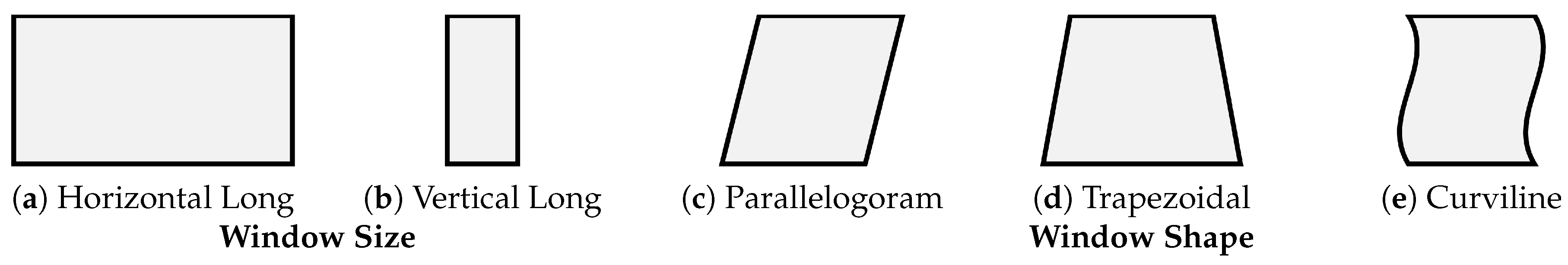
Figure 2.
The cleaning strategy adopted by the experts. Firstly, the experts wash the dirt off by using the scrubber and cleaning liquid (a). Secondly, the dust residue is wiped by squeegee which is manipulated from top to bottom of the window (b). The wiping is done towards a single direction with respect to each column as shown as (b)→(c)→(d).
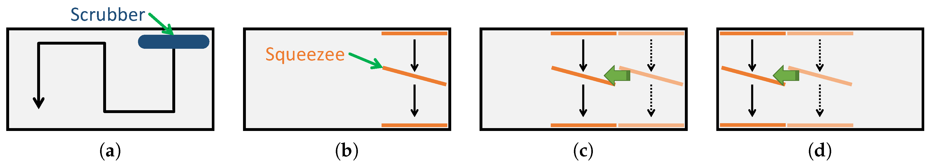
Figure 3.
Nested reconfiguration for the glass façade cleaning robot. Extension and contraction of individual modules helps adapting to window shapes with different shapes (intra-reconfigurability). The robot system adapts to various window shapes by varying the number of intra-reconfigurable modules deployed (inter-reconfigurability). The arrows in the right figure and the dotted lines represent the movement flow and linkages of the modules, respectively.

Figure 4.
Module’s strategy of transition to accomplish the cleaning task. Since the squeegee is installed next to the scrubber, and the glass surface is cleaned by the movement from top to bottom.
Figure 4.
Module’s strategy of transition to accomplish the cleaning task. Since the squeegee is installed next to the scrubber, and the glass surface is cleaned by the movement from top to bottom.
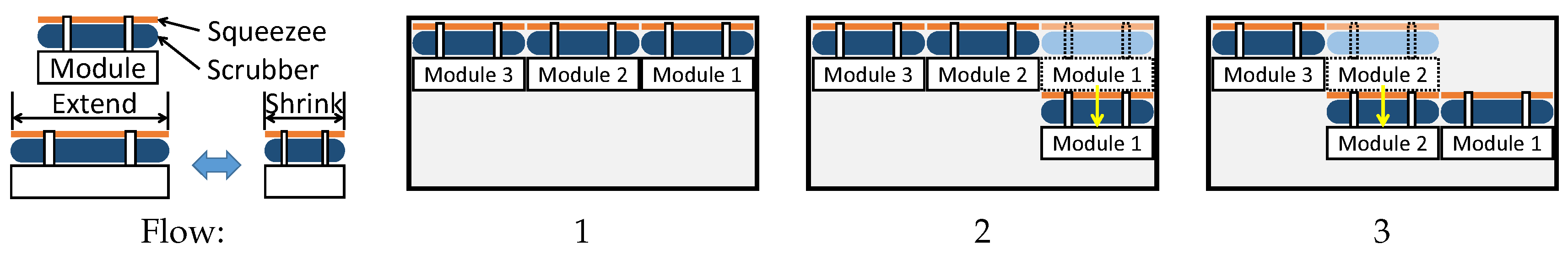
Figure 5.
The CAD design of the module (Left). The modules have the basic structure of three linear actuators, which are equipped like X–Y–Z stage and adhere to the glass surface via suction cups. For the linear actuators in both normal and vertical direction, a ladder chain and sprocket mechanism is adopted (Right).
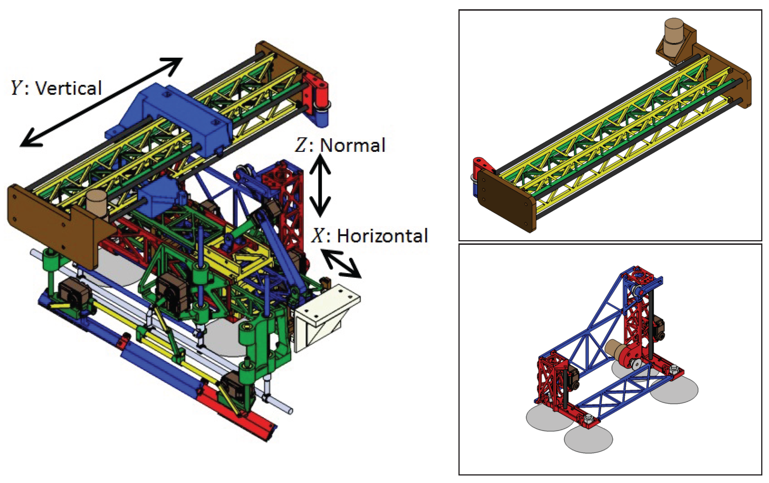
Figure 6.
The movement sequence of an X–Y stage legged robot. The black coloured and white coloured circles represent suction cups with and without vacuum. (a) Vacuum inside the suction cups in the vertical direction are released; (b) the robot tries to make a downward movement; (c) suction cups fails to make contact with the surface and the surface is left uncleaned.

Figure 7.
Movement sequence of the biped-type robot. Orange coloured rectangles represent the cleaning unit in contact with glass surface and green coloured rectangles represents cleaning unit away from the surface. (a) Vacuum inside the suction cups on the right leg is released; (b) the cleaning unit moves towards the bottom edge of the window frame; (c) the cleaning unit returns to the initial position and the vacuum inside suction cups are re-established. The same procedure is repeated on the right leg and cleaning is accomplished.

Figure 8.
The fabricated module prototype (Left). The platform of the nested reconfigurable façade cleaning robot after assembling two modules (Right).
Figure 8.
The fabricated module prototype (Left). The platform of the nested reconfigurable façade cleaning robot after assembling two modules (Right).
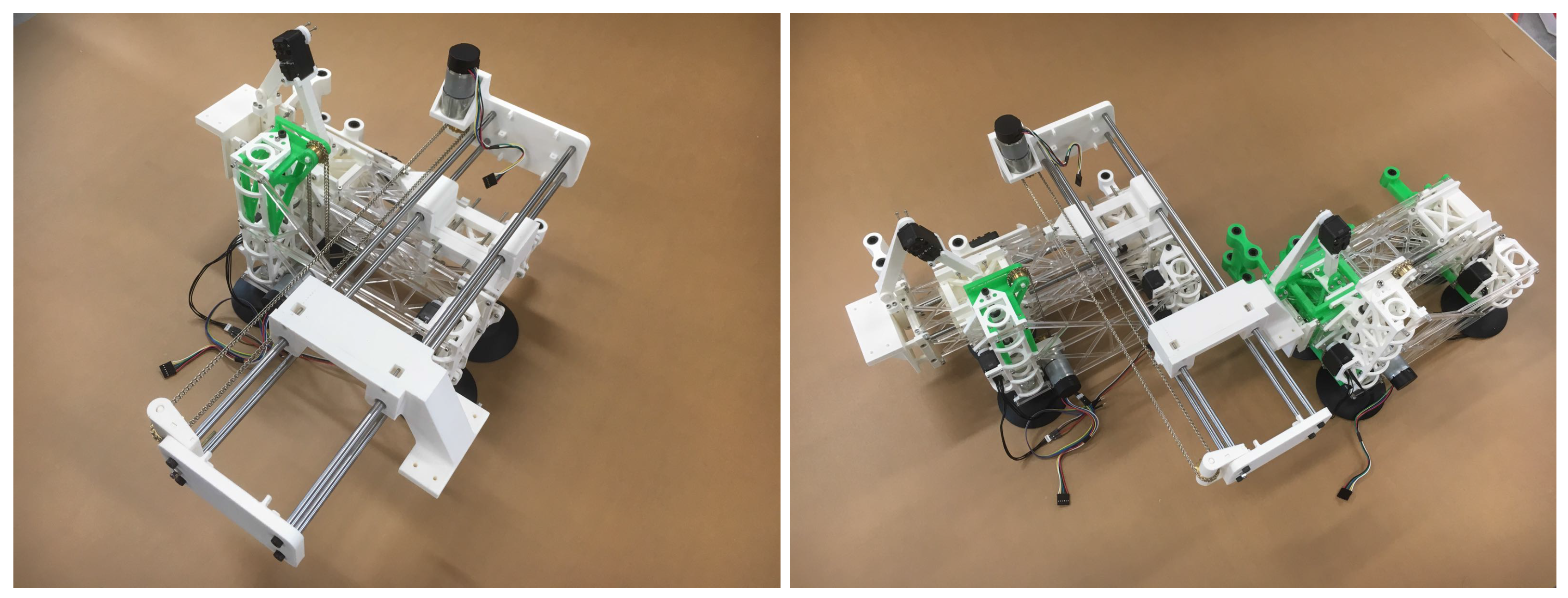
Figure 9.
Parameters definition for the linear actuator in the horizontal direction.

Figure 10.
Handling of the suction cup. (a) Vacuum holding state; (b) vacuum breaking state. The suction is released by pulling the pin.
Figure 10.
Handling of the suction cup. (a) Vacuum holding state; (b) vacuum breaking state. The suction is released by pulling the pin.
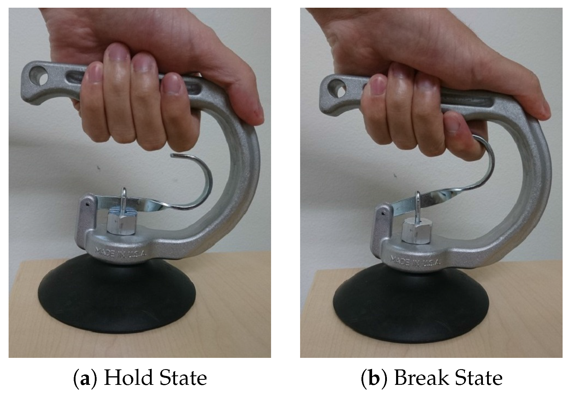
Figure 11.
The relation between required vacuum pressure to the adsorption force.
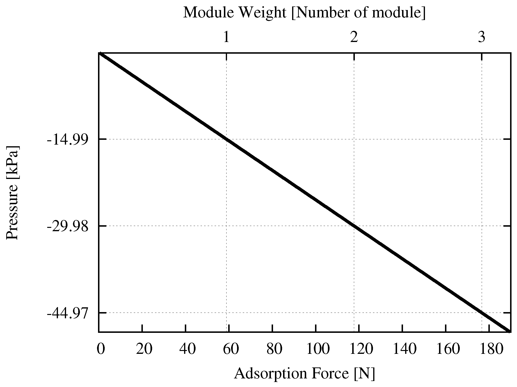
Figure 12.
(Left): The required volume variation corresponding to the adsorption force; (Right): The variation of the required pushing depth corresponding to adsorption force.
Figure 12.
(Left): The required volume variation corresponding to the adsorption force; (Right): The variation of the required pushing depth corresponding to adsorption force.

Figure 13.
Diagram of system architecture. Battery of 11.4 V supply to the DC motors via the DC motor driver. One of 7.4 V supply to the servo motors.
Figure 13.
Diagram of system architecture. Battery of 11.4 V supply to the DC motors via the DC motor driver. One of 7.4 V supply to the servo motors.
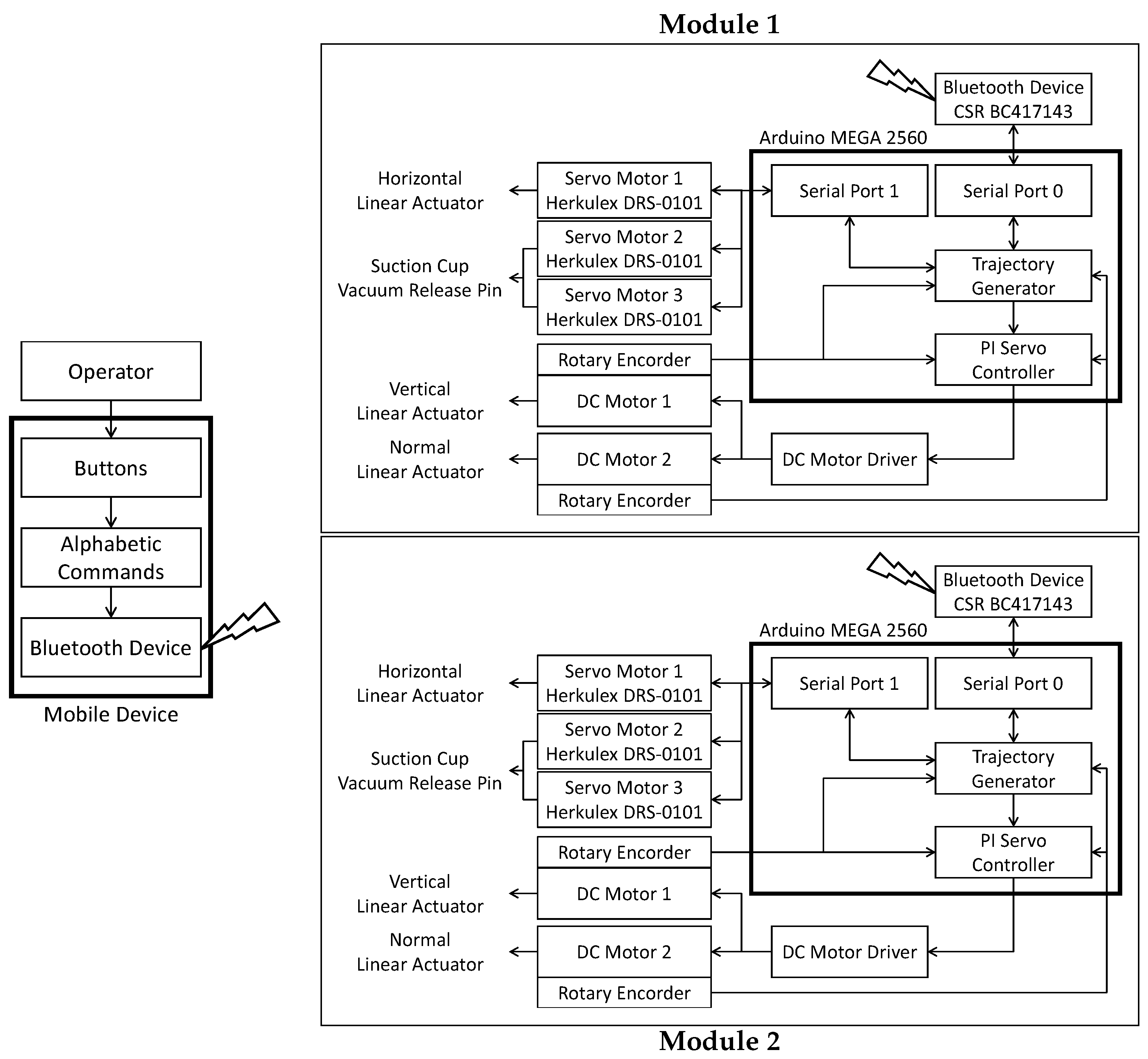
Figure 14.
The snapshots of the experiment. RM and LM represent Right module and Left module, respectively. The experiment start form initial position (a). First, the vacuum of RM is broken (b), and is moved down (c) to bottom (d). After that, RM engages adsorption on the glass surface (e). Secondly, the vacuum of LM is broken (f), and is moved down (g) to neighbor of RM (h). Finally, LM engages adsorption on the glass surface (i) and the experiment is finalize.

© 2017 by the authors. Licensee MDPI, Basel, Switzerland. This article is an open access article distributed under the terms and conditions of the Creative Commons Attribution (CC BY) license (http://creativecommons.org/licenses/by/4.0/).
Share and Cite
MDPI and ACS Style
Nansai, S.; Elara, M.R.; Tun, T.T.; Veerajagadheswar, P.; Pathmakumar, T. A Novel Nested Reconfigurable Approach for a Glass Façade Cleaning Robot. Inventions 2017, 2, 18. https://doi.org/10.3390/inventions2030018
AMA Style
Nansai S, Elara MR, Tun TT, Veerajagadheswar P, Pathmakumar T. A Novel Nested Reconfigurable Approach for a Glass Façade Cleaning Robot. Inventions. 2017; 2(3):18. https://doi.org/10.3390/inventions2030018
Chicago/Turabian StyleNansai, Shunsuke, Mohan Rajesh Elara, Thein Than Tun, Prabakaran Veerajagadheswar, and Thejus Pathmakumar. 2017. "A Novel Nested Reconfigurable Approach for a Glass Façade Cleaning Robot" Inventions 2, no. 3: 18. https://doi.org/10.3390/inventions2030018