
Proof-of-Concept Design for MPP Acoustic Absorbers with Elements of Art


Department of Mechanical Engineering, National University of Singapore, 9 Engineering Drive 1, Singapore 117575, Singapore
*
Author to whom correspondence should be addressed.
Designs 2021, 5(4), 72; https://doi.org/10.3390/designs5040072
Submission received: 22 September 2021
/
Revised: 22 October 2021
/
Accepted: 14 November 2021
/
Published: 16 November 2021
(This article belongs to the Special Issue Environmental Futures: Creative Explorations through Science, Engineering, Design, and Art)
Abstract
:A micro-perforated plate or panel (MPP) is a device used to absorb sound. It consists of a thin flat plate made from several different materials with small holes and a back cavity. Several reported modifications and enhancements to the original design of the MPP acoustic absorber were modified by the holes or the back-cavity shape and sizes following the original idea. The present study attempts to artistically beautify the MPP acoustic absorbers by incorporating dotted arts into the design of MPP. The perforation for micro-perforated panels could be dotted arts with a perforation size smaller than 1 mm for enhanced acoustic absorption performance in the form of various artistic designs. Small LED lights could be placed inside the acoustic chamber to create the color lights emanating from the perforations instead of dots with different colors. Several MPP incorporated artistic designs of dotted patterns were presented and their acoustic absorption performance was analyzed using impedance tube in this paper.
1. Introduction
In recent years, sound-absorbing canvas prints or artworks have gained much attention. With the help of advanced technologies, customized canvas artworks can be printed as per demand. There are several types of existing perforated dot-based paintings. A form of art involving applying colors using small strokes or dots is known as pointillism. It was initially an art movement named after a technique in which small, distinct dotted colors were applied to form an artistic image. Today, there is another more colloquial term known as dotted art, and it describes the application of tiny dots of different colors painted on canvas. There are many other forms of dotted arts. For example, Yuriy Skorohod, a talented artist from Minsk, Belarus, uses a technique called dotwork, drawing on paper using millions of tiny dots. Also, Kevin Sprouls was commissioned by Harper’s in 2016 to create their front cover for their latest issue. He used pointillistic art to create a beautiful portrait to give a farewell tribute to the outgoing US President Barack Obama [1]. Another form of art that could be incorporated with perforation is known as lithophane. A lithophane is an etched or molded artwork in thin translucent porcelain that can be visible when lit with a light source. In the paper, we have explored the novel idea of using such dotted arts in the micro-perforation panels for acoustic absorbers and turning typical acoustic absorbers into an art piece.
Acoustic absorbers or acoustic absorption panels are usually made of polymeric foams or fiber-based materials to enhance sound wave absorption. The traditional acoustic absorbers such as micro-perforated panels (MPPs) and Helmholtz resonators have been used for mid to low-frequency noise absorption [2,3,4,5,6,7]. A typical micro-perforated plate (MPP) sound absorber comprises a thin, flat perforated plate backed by an air cavity. The theoretical background of micro-perforated panel absorbers (MPA) combining microperforated plate covers and an acoustic chamber was initially described by Maa [8] and others [9]. Followed by these initial works, several research publications have been reported on modifications and improvements to the design of MPAs [10,11,12,13,14].
In recent years, several sound-absorbing panels based on artworks have been commercially available globally. For example, GIK acoustics provides various artwork-based acoustic solutions to users in [15]. They even offer the flexibility to choose the art-work design from a library containing millions of images. The customized acoustic art panels are gaining popularity among users. A.M. Acoustics have launched the TELL-US acoustic world map [16]. These artworks have been made using ecoSUND composite, a mixture of recycled Pet-bottles and plant fibers. Also, the design comprises several tiny holes and is backed by an air cavity, an alternative to existing MPP absorber panels. Other examples of decorative design products with acoustic characteristics is hexagonal panels, acoustic letters, acoustic notice boards, screens, free-hanging panels, lamina bars, microperforated pictures, contrast walls, net wires, and chair pads. These renovated sound-absorbent panels or screens and free-hanging products appear visually appealing and exhibit enhanced sound absorption performance.
The present study attempts to modify the existing MPP designs artistically by incorporating dotted arts as the perforated panel. We have presented several artwork-based sound absorbers. Various design prototypes mostly inspired from existing patterns such as television cartoon characters (SpongeBob SquarePants), Telegram stickers (Brown bear), artworks (Mandala art), Poké Ball, and lithophane arts (Snowflakes and Madonna) have been fabricated, and their acoustic performance has been investigated using the impedance tube. These complex features have been developed on thin panels by manually creating an array of dots and 3D printing of a few designs.
2. Theory and Methods
2.1. Theoretical Background
The proposed acoustic absorbers have been designed based on the concept of a micro-perforated plate-type resonator. Micro-perforated plates (MPPs) are plates with tiny perforations (holes) whose diameter is in the order of a millimeter. It has been reported that the MPPs can efficiently absorb sound when they are supported with a back cavity and tuned for a specific frequency range. These plates can be made of various materials from metal to textile. Therefore, their area of utilization is quite broad. The freedom in material choice makes them a promising candidate for sound absorption in diverse and even hostile environments like combustion systems, aircraft engine casings, domestic boilers, and car mufflers. For many years, perforated metal panels (not micro-perforated) with holes in the 1–10 mm range have been used as a cage for sound-absorbing glass-fiber bats where large holes let the sound waves reach into the absorbent fiber. Another use has been creating narrowband Helmholtz absorbers, which can be tuned by hole size and the dimensions of the hole distance and air gap behind the panel. However, when the hole dimensions are in the region of 0.05–1 mm, the narrow absorption peaks become much broader, making the additional fiber absorber more or less unnecessary while maintaining a very high absorption factor. The acoustic performance can be tailored to meet various specifications in diverse applications by varying geometrical and material parameters.
The micro-perforated plate can be analyzed as a corresponding equivalent electrical circuit, as shown in Figure 1. The acoustic system consists of a sub-millimeter perforated plate and a back air cavity between the micro-perforated plate and a rigid wall. The acoustic performance of the sound absorber depends on geometrical parameters such as the perforation diameter d, the plate thickness t, the distance between the centers of adjacent holes b, and the cavity depth D. The acoustic impedance of the micro-perforated plate and the impedance of the back-cavity can be expressed as follows [17]:
The acoustic impedance of the air cavity:
where R and M are the resistive and reactive components of the micro-perforated plate. is the air mass density (kg/m), and c is the speed of sound wave propagation in the air (m/s). The resistive and reactive components can be defined as
and
where k is the perforation constant, is the perforation rate, is the dynamic viscosity coefficient of air (Pa.s), and is the kinematic viscosity coefficient of air (m/s). Also, considering the geometrical effects, the perorated hole length can be modified as mentioned in the Allard Ingard model [18]. The effective hole length can be evaluated from . The end correction terms are defined as , and . Here d is the MPP hole diameter (m).
When sound waves are incident on the micro-perforated plate, the sound absorption coefficient of the acoustic absorber is:
It has been reported that the Maa’s models are not suitable for the heterogeneous micro-perforated panels. Several research works have been presented a modified Maa’s models which include various resistive end correction terms [18,19]. The surface acoustic impedance of a single-layer MPP absorber with an air-back cavity, , can be calculated as
The above equation is normalized by dividing by characteristics impedance of air and can be expressed as, . In Equation (6), is the acoustic impedance of the MPP panel. The acoustic impedance of the air cavity is calculated from Equation (2).
The Modified equation for is given as
In right-hand-side of Equation (7), the first term signifies the viscous energy loss effect inside the micro-perforated hole. The second and third terms refer to the end corrections in acoustic resistance and reactance, respectively. Here, is the effective density, which is expressed by the following equation.
For a circular hole:
where and is the zeroth and first order Bessel function of the first kind, respectively. The parameter is the times the ratio of perforation diameter to the thickness of viscous boundary layer, . Also, in Equation (7), the end correction parameters is defined as, and , if the cross section of the hole edge is rounded. For sharp edge, . For circular hole [20], .
Furthermore, for heterogeneous type MPP absorbers, the perforated holes are confined in the small area of the top cover plate. For simplification, the whole domain can be considered a combination of the synthesized impedance of the part with the holes (homogeneous MPP) and that of the other part without acoustically rigid holes. The overall acoustic impedance of the heterogeneous MPP plate has been calculated as [19],
where is the surface area of the micro-perforated region (approximate) and A is the total surface area of the plate. is the acoustic impedance of the MPP region.
For a normally incident acoustic plane wave, the sound absorption coefficient of the sound absorber can be analytically obtained from the following equation:
2.2. Prototyping
The most straightforward approach for a quick prototyping is based on 3D printing. Fused deposition modeling (FDM) and stereolithography (SLA) are the two most popular types of 3D printers on the market. Both 3D printing technologies have been adapted and refined for the desktop, making them more affordable, user-friendly, and capable. FDM 3D printers work by extruding thermoplastic filaments, such as ABS (Acrylonitrile Butadiene Styrene), PLA (Polylactic Acid), through a heated nozzle, melting the material and applying the plastic layer by layer to a build platform. Each layer is laid down one at a time until the part is complete. The size of the extrusion nozzle limits the minimum resolution of the printed part. Therefore, a tiny feature like micro-perforated holes is difficult to print using the FDM technique. However, FDM printers can still print perforation of the size of 1 mm or slightly smaller. SLA 3D printers use a laser to cure liquid resin into hardened plastic in a process called photopolymerization. A highly precise laser cures liquid resin to form each layer, which can achieve much more delicate details and is more reliable at achieving high-quality results. As a result, SLA 3D printing is known for its delicate features, smooth surface finish, ultimate part precision, and accuracy. The size of the holes can typically go down to about 0.6 mm in diameter for SLA printers.
In this study, FDM has been used to 3D print the design prototypes I, II, III, and IV. Also, the design prototype V has been printed using the SLA technique. Figure 2a shows the 3D printed prototypes. In addition, the complex features of prototypes VI and VII have been manually crafted on PVC sheets. Figure 2b shows the dotted arts manually created using the steel needle of 1 mm diameter. Moreover, the back cavity of two different lengths has been printed using the FDM printer. Figure 3 shows the photographs of the back cavities and assembled prototypes. Other design prototypes have been built in a similar pattern to presented design prototype III. The main reason for these prototypes in the form of 10 cm diameter disks is that the acoustic absorption coefficients can be easily measured using the acoustic impedance tube. For this size, the prototypes could be easily fabricated using 3D printing.
2.3. Measurement of Acoustic Absorption Coefficients
The sound absorption measurements of the acoustic absorbers were performed using the impedance tube setup (50–1600 Hz, Brüel & Kjær, Model Type 4206) in compliance with the standards ISO 10534-2, ASTM E1050-12. In the process, the prototypes were inserted in the sample holder of a diameter of 10 cm. After that, the sound was generated for a specific duration using a speaker mounted at one end of the tube. Two microphones measured the pressure fluctuations of the incident and reflected sound waves at particular locations along the tube. Finally, the absorption coefficient of the mounted sample was processed using the processing software. The processing software interface is user-friendly and provides several outputs like reflection coefficient, absorption coefficients, etc. For all prototypes, five repetitions were taken during the absorption coefficient measurements.
3. Results and Discussion
3.1. Sound Absorption Performance of 3D Printed Micro-Perforated Art Sheet
Figure 4 shows the sound absorption spectra obtained from acoustic absorber prototypes I to V. As shown, a prominent absorbance peak at 396 Hz has been observed for design prototype I, while the absorption performance has been insignificant at most frequencies. The absorption peak of the prototype I is attributed from the thin plate resonance, which can be obtained as [21], , where mm is the radius of the MPP plate, mm is the plate thickness, E = 3.986 GPa is Young’s modulus [22], kg/m is the material density, and is the Poisson’s ratio. The plate-type absorber’s theoretically predicted resonant peak frequency has been calculated as 357 Hz, a relative error of 9.8 % compared with the experimental result.
Also, the absorption performance for prototypes II and IV has been found to be less effective than other prototypes. However, an average absorption coefficient value of ∼0.6 has been achieved from design prototype II in the 1300–1600 Hz frequency range. Moreover, the design prototypes III and V have shown a relatively better sound absorption performance. With prototype III, the sound absorption coefficient value of ≥0.5 has been found between 838 Hz and 1474 Hz, with a maximum absorption peak of 0.96 at 1116 Hz. With prototype V, the sound absorption coefficient value of ≥0.5 has been observed between 670 Hz and 1414 Hz, with a maximum absorption peak of 0.998 at 980 Hz.
3.2. Influence of Back-Cavity Depth on Sound Absorption Performance
Figure 5 shows the variations of the sound absorption coefficient versus frequency for different back cavity depths. A substantial resonant frequency shift towards the lower region has been observed by increasing air cavity depth for both design prototypes (III&V). As noted, for design prototype III, by increasing the back-cavity depth from 2.3 cm to 5 cm, the maximum absorption peak has been shifted from 1116 Hz to 650 Hz. Also, the maximum absorption peak frequency for design prototype V has been lowered from 1116 Hz to 650 Hz with increasing cavity depth. The shifting of resonant peak frequency to lower frequency has been apparent from the acoustic absorbers’ increase in air cavity volume.
Moreover, with the increasing depth of the air cavity, the relative halfwidth of the acoustic absorbers has been increased. The relative bandwidth is defined as the ratio of the width of the frequency band with the sound absorption peak value of ≥0.5 () and the frequency peak at maximum absorption (). As evident from Figure 5, when cavity depth was varied from 2.3 cm to 5 cm, the relative bandwidth of design prototypes III and V increased from 56.9% to 80% and 75.9% to 108%, respectively. The higher relative bandwidth of absorbers affirms the broaden acoustic band with an increasing value of cavity length. However, in the case of design prototype III, the peak value of the acoustic absorption coefficient has been decreased slightly ().
3.3. Broadband Sound Absorption Using Manually Crafted Micro-Perforated Art Sheet
Figure 6 shows the sound absorption spectra measured from the manually crafted MPP art-based sound absorbers. The photographs of the design prototypes VI and VII are shown in Figure 2. Both design prototypes exhibited broadband sound absorption () in the 552–1600 Hz frequency range. These dotted arts possess multi functionalities like a demonstration of dot paintings with broadband sound absorption capabilities.
3.4. Theoretical Analysis and Experimental Comparison
In this section, the sound absorption coefficient of the acoustic absorber has been theoretically estimated, and obtained results have been compared with corresponding experimental data. For a theoretical evaluation of the absorption coefficient, two different models, namely, Maa’s MPP model (Equation (5)) and a modified MPP model (Equation (10)), as explained earlier in Section 2.1 have been used. Figure 7 shows the predicted and measured absorption coefficient spectra of design prototype III. As shown, a theoretical absorbance peak frequency projected from Equation (5) for prototype III with an overall sample thickness of 5.2 cm has been obtained at 642 Hz with a maximum absorbance value of 0.5. While the experimental resonant peak has been observed at 650 Hz with a peak sound absorbance value of 0.86, a slight deviation in absorbance peak frequencies (<5%) can be considered within the permissible range. However, the absorbance peak values obtained from Maa’s model differed significantly from the experimental value. Maa’s model offers a better prediction for homogeneous type MPP absorbers, wherein the micro-perforated holes are uniformly distributed all over the plate.
In the present study, the proposed design prototypes consist of multi-sized holes dispersed in specific patterns in the limited region on the plate. These MPP plates consist of a substantial area without holes equivalent to the rigid plate. Hence, A modified model reported by Kasuka et al. [19] has been used to predict the sound absorption performance of the proposed design prototypes. As shown in Figure 7, using the modified model, the absorbance peak value has been calculated as 0.86, comparable with experimental result. However, a slight difference in peak frequency has been realized. The 3D-printed MPPs have poor manufacturing accuracy; the perforated holes are not a perfect circle. The irregular shape of MPP holes results in a change in the flow resistance value in the theoretical prediction and perforation ratio. These significantly affect the theoretical prediction accuracy [23].
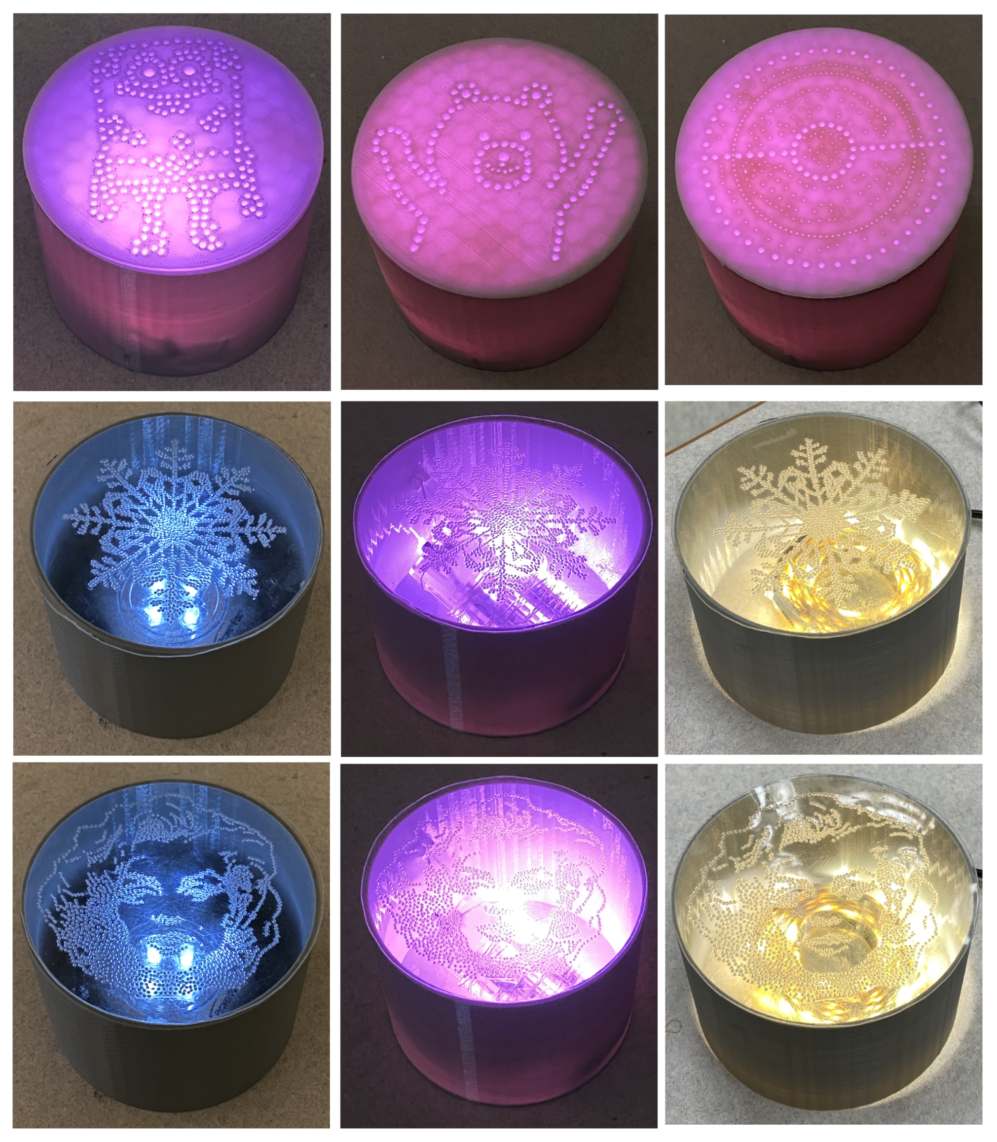
3.5. Demonstration of Dotted Arts-Based Absorbers with LED Light
Figure 8 shows the possible decorative designs of the presented dotted art acoustic absorbers. As shown, each absorber embedded LED lights inside the back cavity. These attractive designs can find potential uses in residential applications such as ambient lighting, decorative lighting, dimming, etc. Also, these designs are scalable and can be manufactured for large-scale applications.
4. Conclusions
This paper presented proof-of-concept designs for MPP acoustic absorbers with the elements of art. Various micro-perforated dotted art structures have been designed and fabricated using 3D printing. Moreover, the acoustic performance of these acoustic absorbers has been investigated using an impedance tube. Furthermore, the sound absorption characteristics have been theoretically estimated using Maa’s MPP model and a modified model for heterogeneous MPP sound absorbers. The theoretical and experimental results have shown significant sound absorption at specific frequencies. The outcomes of this study have demonstrated excellent potential for these dotted art designs to be scaled up. A large-size MPP dotted artwork could also be manufactured using conventional machining techniques such as CNC drilling or laser hole drilling.
In addition, LED lights could be embedded inside the back cavity for interior decorative applications to create unique lighting effects. For actual applications, the MPP-based sound-absorbing panels need to be fabricated using building standard strong materials. Possible design modifications could include thicker panels, elastic support to stiffen the MPP panels, and use of honeycomb-shaped air cavity to support the thin MPP panels [24].
Author Contributions
Conceptualization, H.P.L. and S.K.; methodology, S.K. and J.W.A.; software, S.K.; validation, H.P.L., S.K. and J.W.A.; formal analysis, S.K. and J.W.A.; investigation, H.P.L. and S.K.; resources, H.P.L. and J.W.A.; data Creation, S.K. and J.W.A.; writing—original draft preparation, H.P.L. and S.K.; writing—review and editing, H.P.L. and S.K.; visualization, S.K. and J.W.A.; supervision, H.P.L.; project administration, H.P.L.; funding acquisition, H.P.L. All authors have read and agreed to the published version of the manuscript.
Funding
The second author would like to acknowledge the financial support from the Ministry of Education RSB Research Fellowship, Singapore. The authors would like to acknowledge the financial support from the Ministry of Education under the Tier 1 Academic Research Grant (R-265-000-A24-114).
Institutional Review Board Statement
Not applicable.
Informed Consent Statement
Not applicable.
Data Availability Statement
Data can be provided on request from first author.
Acknowledgments
We sincerely appreciate the participation of the students from ME5106 engineering acoustics, Department of Mechanical Engineering, National University of Singapore, in design challenge tasks.
Conflicts of Interest
The authors declare no conflict of interest.
References
- Getting Presidential | Presidential Art, Part 3—Ink Rhythm. Available online: https://www.sprouls.com/blog/2015/09/getting-presidential-presidential-art/ (accessed on 15 September 2021).
- Kumar, S.; Bhushan, P.; Bhattacharya, S. Ultrathin Ashoka Chakra like acoustic metastructure as a sound absorber. J. Acoust. Soc. Am. 2018, 143, 1714. [Google Scholar] [CrossRef]
- Kumar, S.; Lee, H.P. The present and future role of acoustic metamaterials for architectural and urban noise mitigations. Acoustics 2019, 1, 590–607. [Google Scholar] [CrossRef] [Green Version]
- Kazuma, H.; Toshiki, H.; Takeshi, O.; Sakagami, K.; Yairi, M.; Harada, S.; Takahashi, S.; Ueda, Y. Implementation experiment of a honeycomb-backed MPP sound absorber in a meeting room. Appl. Acoust. 2020, 157, 107000. [Google Scholar] [CrossRef]
- Sakagami, K.; Kusaka, M.; Okuzono, T.; Kido, S.; Yamaguchi, D. Diffuse-field sound absorption characteristics of a spherical-microperforated space absorber. Acoust. Sci. Technol. 2020, 41, 784–787. [Google Scholar] [CrossRef]
- Kumar, S.; Xiang, T.B.; Lee, H.P. Ventilated acoustic metamaterial window panels for simultaneous noise shielding and air circulation. Appl. Acoust. 2020, 159, 107088. [Google Scholar] [CrossRef]
- Ciaburro, G.; Iannace, G. Numerical Simulation for the Sound Absorption Properties of Ceramic Resonators. Fibers 2020, 8, 77. [Google Scholar] [CrossRef]
- Maa, D.-Y. Theory and design of micro perforated-panel sound-absorbing construction. Sci. Sin. 1975, 18, 55–71. [Google Scholar]
- Cobo, P.; Simón, F. Multiple-Layer Microperforated Panels as Sound Absorbers in Buildings: A Review. Buildings 2019, 9, 53. [Google Scholar] [CrossRef] [Green Version]
- Carbajo, J.; Ghaffari Mosanenzadeh, S.; Kim, S.; Fang, N.X. Sound absorption of acoustic resonators with oblique perforations. Appl. Phys. Lett. 2020, 116, 54101. [Google Scholar] [CrossRef]
- Wang, C.; Cheng, L.; Pan, J.; Yu, G. Sound absorption of a micro-perforated panel backed by an irregular-shaped cavity. J. Acoust. Soc. Am. 2010, 127, 238. [Google Scholar] [CrossRef] [PubMed] [Green Version]
- Kim, K.H.; Yoon, G.H. Absorption performance optimization of perforated plate using multiple-sized holes and a porous separating partition. Appl. Acoust. 2017, 120, 21–33. [Google Scholar] [CrossRef]
- Xu, Z.; He, W.; Peng, X.; Xin, F.; Lu, T.J. Sound absorption theory for micro-perforated panel with petal-shaped perforations. J. Acoust. Soc. Am. 2020, 148, 18–24. [Google Scholar] [CrossRef] [PubMed]
- Gao, N.; Hou, H. Experimental investigation of sound absorption in a composite absorber. Theor. Appl. Mech. Lett. 2021, 58–62, 100221. [Google Scholar] [CrossRef]
- Acoustic Art Panels—GIK Acoustics—Sound Absorbing Wall Art. Available online: https://gikacoustics.eu/product-category/acoustic-art-panels (accessed on 20 September 2021).
- TELL-US Acoustic World Map | Akustikmiljö. Available online: https://www.amacoustics.com/products/tell-us-acoustic-world-map (accessed on 20 September 2021).
- Maa, D.-Y. Potential of microperforated panel absorber. J. Acoust. Soc. Am. 1998, 104, 2861–2866. [Google Scholar] [CrossRef]
- Atalla, N.; Sgard, F. Modeling of perforated plates and screens using rigid frame porous models. J. Sound Vib. 2007, 303, 195–208. [Google Scholar] [CrossRef]
- Kusaka, M.; Sakagami, K.; Okuzono, T. A Basic Study on the Absorption Properties and Their Prediction of Heterogeneous Micro-Perforated Panels: A Case Study of Micro-Perforated Panels with Heterogeneous Hole Size and Perforation Ratio. Acoust. Multidiscip. Digit. Publ. Inst. 2021, 3, 473–484. [Google Scholar] [CrossRef]
- Cox, T.; d’Antonio, P. Acoustic Absorbers and Diffusers: Theory, Design and Application, 3rd ed.; CRC Press: Boca Raton, FL, USA, 2016. [Google Scholar] [CrossRef]
- Kumar, S.; Bhushan, P.; Prakash, O.; Bhattacharya, S. Double negative acoustic metastructure for attenuation of acoustic emissions. Appl. Phys. Lett. 2018, 112, 101905. [Google Scholar] [CrossRef]
- Pinto, V.C.; Ramos, T.; Alves, S.; Xavier, J.; Tavares, P.; Moreira, P.M.G.P.; Guedes, R.M. Comparative failure analysis of PLA, PLA/GNP and PLA/CNT-COOH biodegradable nanocomposites thin films. Procedia Eng. 2015, 114, 635–642. [Google Scholar] [CrossRef] [Green Version]
- Sakagami, K.; Kusaka, M.; Okuzono, T.; Nakanishi, S. The Effect of deviation due to the manufacturing accuracy in the parameters of an MPP on its acoustic properties: Trial production of MPPs of different hole shapes using 3D printing. Acoustics 2020, 2, 605–616. [Google Scholar] [CrossRef]
- Sakagami, K.; Morimoto, M.; Yairi, M. Application of microperforated panel absorbers to room interior surfaces. Int. J. Acoust. Vib. 2008, 13, 120–124. [Google Scholar]
Figure 1.
Schematics of the micro-perforated plate and its equivalent circuit diagram.
Figure 2.
(a) 3D-printed sound absorber designs. (b) manual dotted art designs. Prototype I–VII: thin plate, SpongeBob SquarePants, Brown bear, Mandala art, Poké Ball, Snowflakes, and Madonna.
Figure 2.
(a) 3D-printed sound absorber designs. (b) manual dotted art designs. Prototype I–VII: thin plate, SpongeBob SquarePants, Brown bear, Mandala art, Poké Ball, Snowflakes, and Madonna.

Figure 3.
Photographs of the acoustic absorber prototype III. (a) Air cavities with two different depths of 2.3 cm and 5 cm. (b) Assembled prototypes.
Figure 3.
Photographs of the acoustic absorber prototype III. (a) Air cavities with two different depths of 2.3 cm and 5 cm. (b) Assembled prototypes.

Figure 4.
Sound absorption performance of the various design prototypes (I–V).
Figure 5.
Effect of back cavity depth on the overall sound absorption performance of design prototypes III and V.
Figure 5.
Effect of back cavity depth on the overall sound absorption performance of design prototypes III and V.
Figure 6.
Broadband sound absorption performance of the design prototypes VI and VII.
Figure 7.
The predicted and measured absorption coefficients of acoustic absorber (design prototype III).
Figure 7.
The predicted and measured absorption coefficients of acoustic absorber (design prototype III).

Figure 8.
Photographs of the dotted art acoustic absorber prototypes.
Publisher’s Note: MDPI stays neutral with regard to jurisdictional claims in published maps and institutional affiliations. |
© 2021 by the authors. Licensee MDPI, Basel, Switzerland. This article is an open access article distributed under the terms and conditions of the Creative Commons Attribution (CC BY) license (https://creativecommons.org/licenses/by/4.0/).
Share and Cite
MDPI and ACS Style
Lee, H.P.; Kumar, S.; Aow, J.W. Proof-of-Concept Design for MPP Acoustic Absorbers with Elements of Art. Designs 2021, 5, 72. https://doi.org/10.3390/designs5040072
AMA Style
Lee HP, Kumar S, Aow JW. Proof-of-Concept Design for MPP Acoustic Absorbers with Elements of Art. Designs. 2021; 5(4):72. https://doi.org/10.3390/designs5040072
Chicago/Turabian StyleLee, Heow Pueh, Sanjay Kumar, and Jie Wei Aow. 2021. "Proof-of-Concept Design for MPP Acoustic Absorbers with Elements of Art" Designs 5, no. 4: 72. https://doi.org/10.3390/designs5040072