Design of a Gasification Reactor for Manufacturing and Operation in West Africa
by
 , , ,
, , ,
Laetitia Zoungrana
1,2,* ,
,
Sayon dit Sadio Sidibé
1,
Benoît Herman
2,
Yézouma Coulibaly
1 and
Hervé Jeanmart
2,* 1
Laboratoire Energie Renouvelable et Efficacité Energétique, Institut International d’Ingénierie de l’Eau et de l’Environnement (2iE), Ouagadougou 01 BP 594, Burkina Faso
2
Institute of Mechanics, Materials and Civil Engineering, Université Catholique de Louvain (UCLouvain), 1348 Louvain-la-Neuve, Belgium
*
Authors to whom correspondence should be addressed.
Designs 2021, 5(4), 76; https://doi.org/10.3390/designs5040076
Submission received: 25 October 2021
/
Revised: 23 November 2021
/
Accepted: 25 November 2021
/
Published: 30 November 2021
Abstract
:This paper introduces the design of a biomass gasification reactor with specific constraints for its manufacturing and operation in the West African conditions. The foreseen applications are the valorisation into heat and electricity of agricultural biomass residues. Rice husk is chosen as the reference fuel for the design. Local manufacturing is a key feature and the main focus of the design, as it allows us to reduce the capital costs and facilitate the maintenance. The design methodology is based on the conceptual approach proposed by Cross. This approach leads in several steps to a rational design choice based on the evaluation of different solutions. In this study, nine reactor types have been compared leading to a prototype that best suits the defined objectives such as a local manufacturing, a secure installation and a sufficient gas quality. From this conception approach, the Semi-Batch, Fixed-bed reactor with air Aspiration appears the most suitable. Its specific characteristics for the foreseen application are a power of 44 kW based on the syngas lower heating value, an average fuel consumption of 20.38 kg/h and an average air flow of 28.8 kg/h for optimal gasification. The gasifier resulting from the design methodology has been built. It is presented in the paper.
1. Introduction
During the past decades, modern electricity access in West African countries has been growing up steadily from 33% in 2000 to 54% 2018 [1]. This increase is accompanied by the growth of renewable energy to fulfil the electricity access [2]. In West Africa, the share of renewable energy (made of biomass, hydro, wind, geothermal, concentrating solar power and solar photovoltaics) could further increase from 22% in 2010 to at least 52% in 2030 [3]. However, due to the rapid growth of the population and to the urbanisation and the related needs, basic modern energy services such as lighting, improved cooking and telecommunication remain largely unsatisfied for the rural populations [4].
In Burkina Faso, the national rate of electrification was estimated at 20% in 2018, while in rural areas this rate remained as low as 5% [1]. In addition to the expansion of the national grid, covering the electrification gap in rural areas requires the development of local small-scale energy production units. These units should be conceived to be easily adopted by the local populations while meeting the criteria of sustainable energy such as low CO2 emissions. Many projects based on solar energy, both photovoltaic and concentrated solar power, have been developed as a source of renewable energy [5,6,7]. They have great advantages but also some weaknesses, such as the need to store the energy during the day for the electricity demand during the evening and the night. West African countries have also a large biomass potential from different resources, including agricultural residues, which are not yet valorised. In this perspective, the gasification of biomass could be an interesting approach for energy production [8]. However, despite the potential of the gasification process for heat and/or electricity production, the number of effectively operating biomass gasification units in West Africa remains very low, as there are still many identified gaps to be addressed. Indeed, most gasifiers on the local market are expensive imported technologies from Europe or India. They are difficult to operate and maintain by local users, which hinders their successful adoption [9]. There are also locally handcrafted technologies that often exhibit design issues once in operation. These issues can be harmful gas leaks or unsuitable materials leading to rapid mechanical failures.
In view of these difficulties, which prevent the establishment of gasification technology in West Africa, the present study aims to contribute to the development of the gasification sector by following a design methodology for a gasifier considering the specific needs of the rural users and the local constraints. To illustrate the design approach, the current needs of a semi-industrial cooperative established in the locality of Bama in Burkina Faso are considered. This semi-industrial cooperative produces rice. Electricity is required to husk the paddy rice producing rice husk as residues, that could be used in a gasifier to generate the electricity to run the husker. The electricity would be produced by an internal combustion engine running on the producer gas from the gasifier. Heat from the cooling system and the exhaust of the engine could be recovered to reduce the thermal energy needed to parboil the rice. In this paper, the focus is on the reactor itself and not on the whole gasification facility including the gas cleaning unit and the engine.
A specific conceptual methodology must be considered to rethink in detail the layout, structure and manufacturing of a gasifier which could lead to the installation of more suitable units, thus answering the needs and expectations of West African populations. Pahl and Beitz proposed such a methodology. It allows a systematic approach in the design of a new product and is defined in four steps: planning and clarification, conceptual design, embodiment design and detail design [10]. Ulrich and Eppinger proposed a similar methodology but added an additional step: production and ramp-up, which is the first step of the product manufacturing [11]. Later, Cross [12] contributed to the development of design thinking, which, contrary to systematic methods, is more creative. He defined the design as a crossroads of arts, sciences and technologies. The present gasifier design study is based on the methodology proposed by Cross. It focuses on designing and building a gasification reactor mainly using the resources available locally in West Africa. Among others, it takes into consideration the energy need, the safety and durability of the reactor as well as criteria for an easy operation of the reactor.
2. Methodology
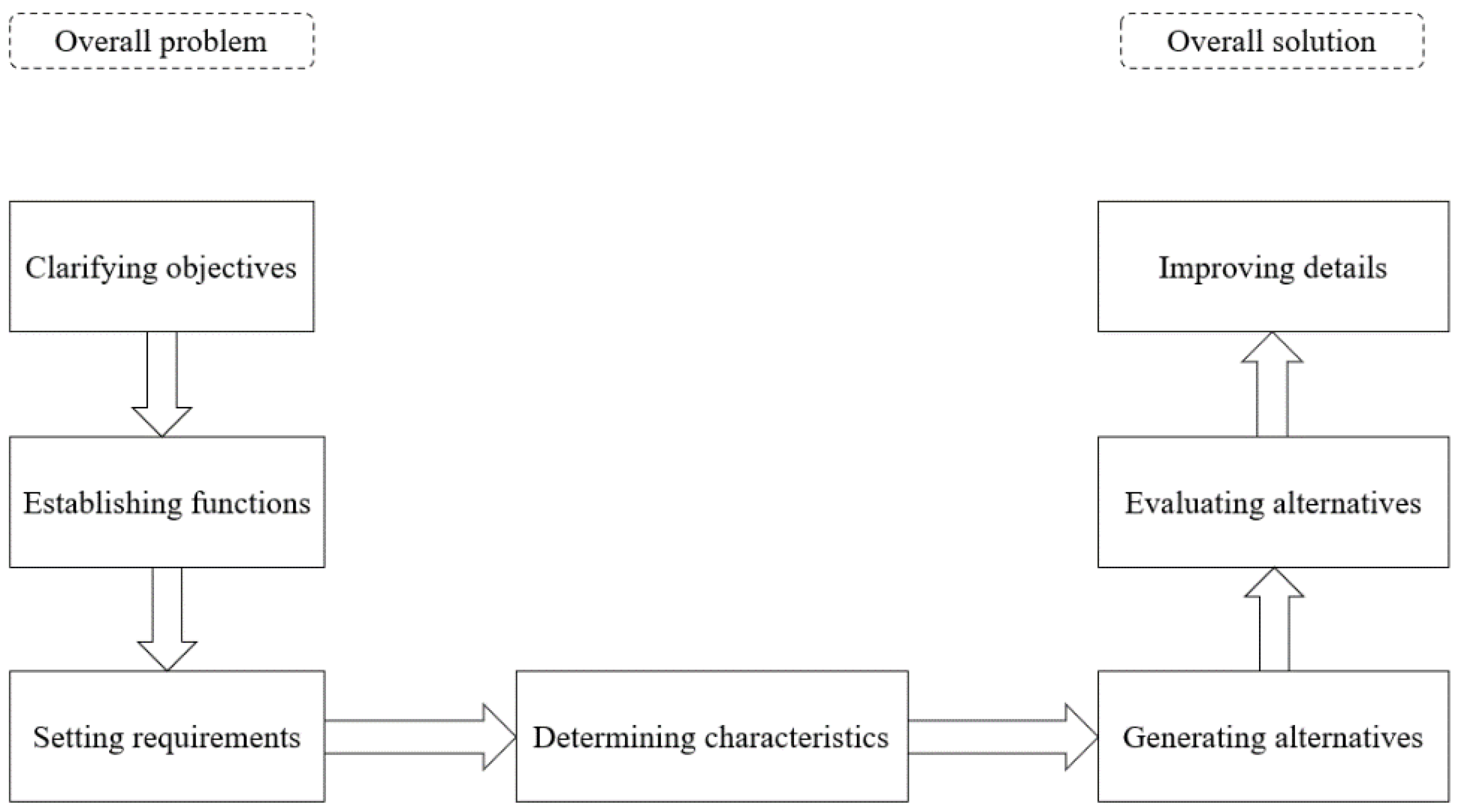
The methodology proposed by Cross [12] was used for the design of the reactor to obtain a conceptual design meeting the set objectives. This methodology revolves around various major steps, going from the definition of the objectives to the realisation of blueprints for manufacture. The methodology is subdivided into seven stages (see Figure 1): clarifying objectives, establishing functions, setting requirements, determining characteristics, generating alternatives, evaluating alternatives and improving details.
2.1. Clarifying Objectives
The main objective is to design a gasification reactor adapted to the needs of the West African small-scale industries, particularly in Burkina Faso chosen as the experimental site. The technology to be designed must be manufactured locally while meeting high quality and security requirements. For this, specific parameters were considered as danger of explosions and danger of poisoning due to leakage of producer gas into the environment, especially during human actions.
One of the main challenges is to manufacture a reactor suited not only for moderate use in a dedicated environment (e.g., a laboratory) but also for its sale and use in small companies such as agro-industries. However, the prototype to be built and tested at the completion of the design methodology will be scaled to fit into a lab environment.
The requirements for the reactor were subdivided into several objectives based on the identified local needs and aspirations. For this first step, the deliverable is the graph of the objectives. The overarching objective of designing a gasification reactor is divided into ten main objectives. These ten objectives are ranked by order of importance. To achieve this, a logical framework matrix has been implemented. Then, on a scale of 1 to 100, these ten objectives were weighted according to the study context with the sum of all the weights equal to 100. The objectives and their weights are reported in Table 1. The emphasis is on a local manufacturing and a safe installation. The gas quality and the lifetime of the gasifier come next. Less important objectives, such as the capacity and the multifuel capability, have low weights.
The ten objectives are further split into primary and secondary subobjectives in order to refine the expressed needs. Local manufacturing includes both the use of local materials and local labour. The safety of the installation concerns the protection from risky elements (e.g., high-temperature parts) and the control of ambient gases which are potentially dangerous for the health of the operators. The gas produced by the prototype must also be combustible in an engine and have a low fraction of tars. In addition, the reactor must be resistant to thermal cycles, high temperatures and corrosion [13]. For instance, the material for the gasifier walls must be as noble as possible because elements such as sulphur and nitrogen increase the corrosion risk at high temperature [14].
The gasifier should allow a maximum conversion of the fuels, by having good gas yields and low carbon residues. The use and maintenance must be accessible to a large number of trained users. The monitoring and the change of the operating parameters must be simple operations. Disassembly and reassembly for maintenance should be easy and with relatively long maintenance intervals. The reactor must be environmentally sustainable, complying with small-scale gasification plant standards for atmospheric and soil pollution. The gasifier could release toxic gases for the environment and for the users such as CO, H2S and NH3. Ashes are usually harmless with elements such as alumina Al2O3, silicon oxide SiO2, iron oxide Fe2O3 and calcium oxide CaO [15].
Multiple local fuels must be potentially admissible within the reactor (with a light pretreatment) in order to meet the local fuel availability. Finally, the capacity of the reactor should meet the daily demand for energy.
Then, after defining the subobjectives linked to the ten main objectives, relative weights and absolute weights are assigned to these objectives and subobjectives according to their importance. The sum of the ten main objective weights is 100; at lower levels the primary and secondary subobjectives are then given weights relative to each other but with also a total of 100. Their overall weights are calculated as a fraction of the absolute weight of the objective above them as shown in Equation (1).
where n + 1 is the level to designate the weight of an objective and n is the level to designate the weight of a subobjective. All the objectives and subobjectives are given two values: their value relative to their neighbours at the same level and their true value or value relative to the overall objective. In Table 1, the assigned real and relative weights of the objectives are given.
2.2. Establishing Functions
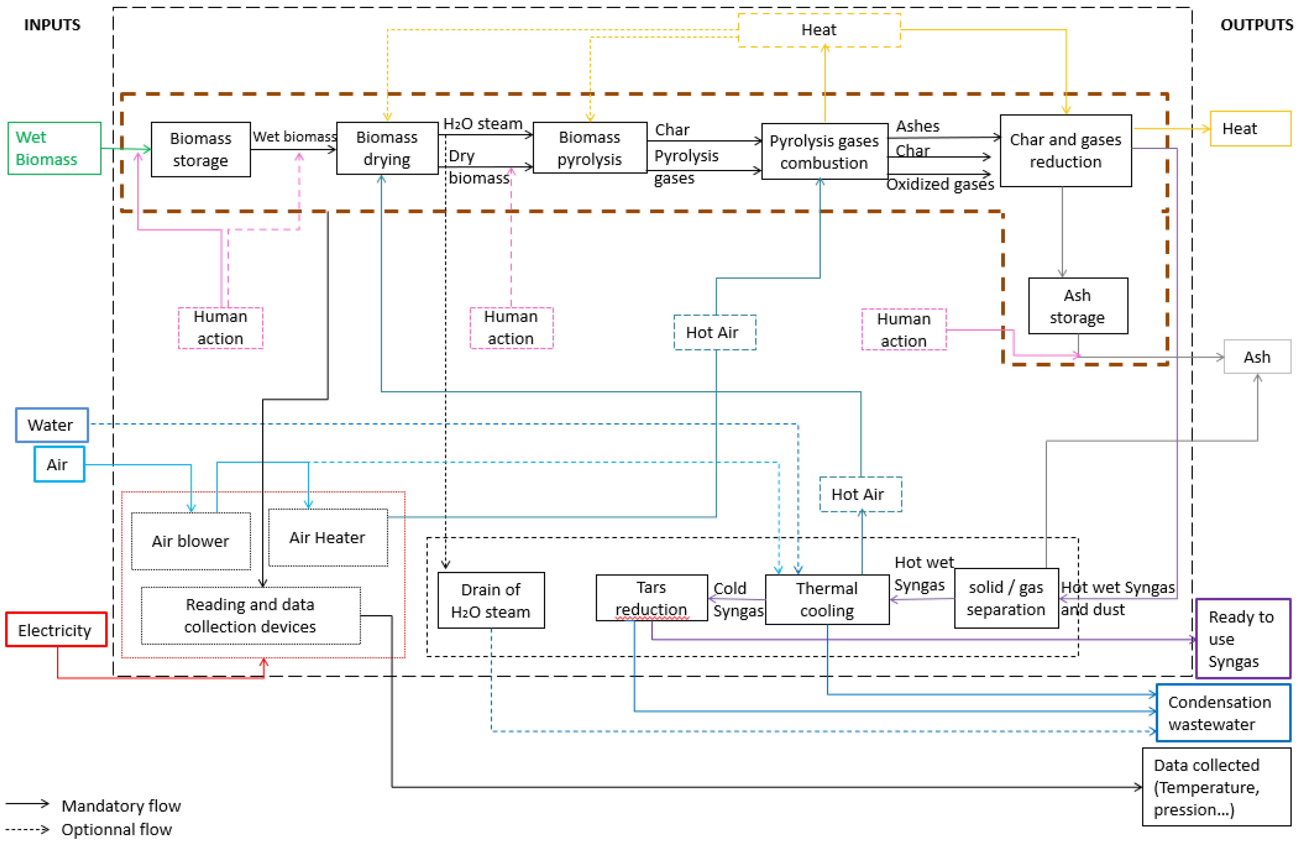
Once the objectives are defined and the weights set, the means by which these objectives can be achieved must be defined. To frame this process, the gasification process has been split into multiple unitary operations, called functions. All these functions act either simultaneously or one after the other, to constitute the gasification process. This step is materialised with a functional analysis that represents all the functions of the system that allow us to achieve the previously defined objectives, as illustrated in Figure 2. In the figure, a summary of the functional analysis of the gasifier is represented first as a black box (dashed lined) with inputs and outputs. Then, this black box is broken down into subfunctions to detail the four stages necessary in a gasification process, namely: drying, pyrolysis of the biomass, oxidation of the gases and reduction of the char [16]. Finally, the functional analysis is deepened by further detailing the functions which can still be fragmented for more precision. As presented in Figure 2, the main inputs in the gasification system are biomass and air. Biomass is stored within the gasifier and transformed by the heat from the oxidation. Biomass is thus dried and pyrolyzed. The outlet flows from the pyrolysis function are charcoal and pyrolysis gases that are oxidised in a fuel rich environment. The last steps are the reduction of the char and the storage of ashes. At this stage of the gasification the outputs are ashes (including residual char) and a raw syngas. The raw syngas flow goes into the cleaning functions: the syngas is filtered from its solid particles, and then cooled and cleaned from tars. The cold and cleaned syngas is then ready to be used in an engine for electricity production or to be burnt for heat generation. Other functions are also mentioned in the functional analysis; they are the necessary functions that allow us to enter the gasification agent (air in this case) into the gasifier and collect data from the main functions. In the functional analysis, two types of flow are defined: mandatory flows and optional flows. For example, water is an optional flow entered into the syngas thermal cooling function. The syngas can be dry cooled. Additionally, the human action can be optional between the biomass storage and the biomass drying. In fact, biomass can be stored in a container physically separated from the gasifier, then the user conveys the biomass from the container to the gasifier, or the container can be connected directly to the gasifier by a conveyor that does not require a human action.
2.3. Performance Specification
The third stage of the design consists of specifying, quantitatively or qualitatively, the expressed objectives, functions and needs. This stage allows us to set and to quantify the level of requirement, reliability, safety and attainment of the gasification technology to be designed. The stage has been organised in different sections: performance requirements, manufacturing requirements, operating requirements and security constraints. The definition of the amount of energy to be produced by the gasifier is a key specification. It dictates the size of the installation but also other characteristics of the reactor. Here, the energy requirement has been quantified based on a small industrial rice husking unit. This scenario corresponds to a representative use of a gasifier. This type of units uses, among others, a huller with a nominal power of around 10 kW (11 kW chosen for the design). This electrical power is within the representative range of potential needs that can be met by a small-scale gasification platform. On this basis, it is possible to define the amount of electrical energy to be produced to operate this machine during a working day considered as 10 h of operating time. In order to produce electricity, an engine coupled to an alternator is fed with the gas produced by the gasifier [9,17]. The engine efficiency is estimated at 25% in the design phase [17]. Therefore, the gas power should be around 44 kW. The gasifier efficiency, i.e., the energy in the gas compared to the energy of the feedstock, is estimated at 60%. The remaining 40% is lost in heat and other losses (e.g., partially converted biomass). The input power is thus around 75 kW in terms of the lower heating value of the (dry) feedstock. The considered feedstock for this study is rice husk. It is a suitable fuel for gasification [18,19,20]. The immediate analysis of rice husk performed by Casaca and Costa [21] is presented in Table 2.
The apparent density of rice husk is estimated at 120 kg/m3 and the lower heating value is chosen as 3.6 kWh/kg. Thus, the daily required rice husk quantity is 200 kg/day. Based on this specification, different solutions for the gasifier can be generated as described in the next section.
2.4. Generating Solutions
To generate solutions established on the objectives and subobjectives, functions and performances, several technological options have been compared. In order to organise the different possibilities or alternatives for the gasifier to be designed, three functions considered as fundamental were the starting point for generating solutions. These three functions are: the mode of fuel feeding, the mode of supplying the gasification agent (air in this case) within the gasifier and the type of reactor. Therefore, the solutions are first generated combining different solutions for the three main functions. These are then evaluated to select the most suitable for the selected application.
2.4.1. The Fuel Supplying Method
Regarding the feeding of biomass into the reactor, the fuel could be introduced all at once at the beginning of the gasification process, in a batch mode. In the batch supply, an operator manually puts biomass into the gasification reactor. Then, the operator closes the reactor before initiating the reactions. The autonomy of the gasifier in batch mode is determined by the depletion of the fuel inside the unit. Thus, the reactor has a volume sized according to the necessary operating time and the required power. Consequently, this operating time is, most of the time, limited to a few hours per day. However, the batch feeding mode is relatively autonomous for the duration of its operation and does not require additional intervention by the operator or any mechanism. Therefore, in a batch reactor, the operator works mainly during the biomass loading and the ashes discharging times. For a small installation, a batch supply limits the costs related to the management of the installation: the reduction in the tasks entrusted to the operator as well as the reduction of the costs related to the capital costs of the automation. Specificity with this type of feeding is related to the regularity in the composition of the gas, which is observed only during the cruising phase of a cycle. Introduction of biomass for a new cycle results in a break in the composition of the gas at the start of the cycle before getting a good quality syngas in the cruise phase of the cycle [22]. Moreover, in Patel’s study [23], the longer residence time of the biomass in the reactor (at a defined temperature) in batch mode allowed better conversion of the fuel and lower tar residues. Another advantage of the batch supply was described by Daouk [24]. In his experimental study, Daouk performed a comparison between the batch and continuous wood supply of an oxidising pyrolysis reactor. He found that the fuel consumption differed. He estimated the fuel consumption, in kg/s, based on Equation (2):
where is the wood density (kg/m3), is the speed of oxidation zone (m/s) and is the gasifier section (m2). Then, for a fixed air flow, the wood consumption was 3.73 kg/h for a continuous fuel supply against 1.66 kg/h for a batch fuel supply. The low rate of fuel consumption in batch allows a longer residence time of fuel and a better conversion of fuel at the cost of a more voluminous reactor.
In contrast to the batch method, the biomass could be continuously fed into the reactor. A continuous supply of the fuel has some advantages, the main one being a longer gasification process without time restriction and independent of the size of the gasifier [18,19]. The continuous biomass supply is commonly carried out by means of an electric automation, based on the solid bed levels in the reactor. Inversely to the batch supply, in a continuous supply, the loading and discharging processes are automatic [25]. Thus, the continuous supply mode is defined by a larger number of auxiliaries compared to the batch. This supply method must be performed continuously at regular intervals in order to maintain a cyclical rhythm in terms of inputs, keeping a more constant gas quality. The ashes must also be regularly removed to allow continuous recharging of the biomass [24]. As a consequence, the continuous supply system is more prone to gas leaks (input of biomass and extraction of ashes). The continuous supply method also imposes more constraint on the pretreatment (especially the size) of biomass particles before gasification. Therefore, the gasification process requires additional control points, more space occupation as well as additional operational costs. Its mechanism being more complex, it is more sensitive to the quality of the manufacturing.
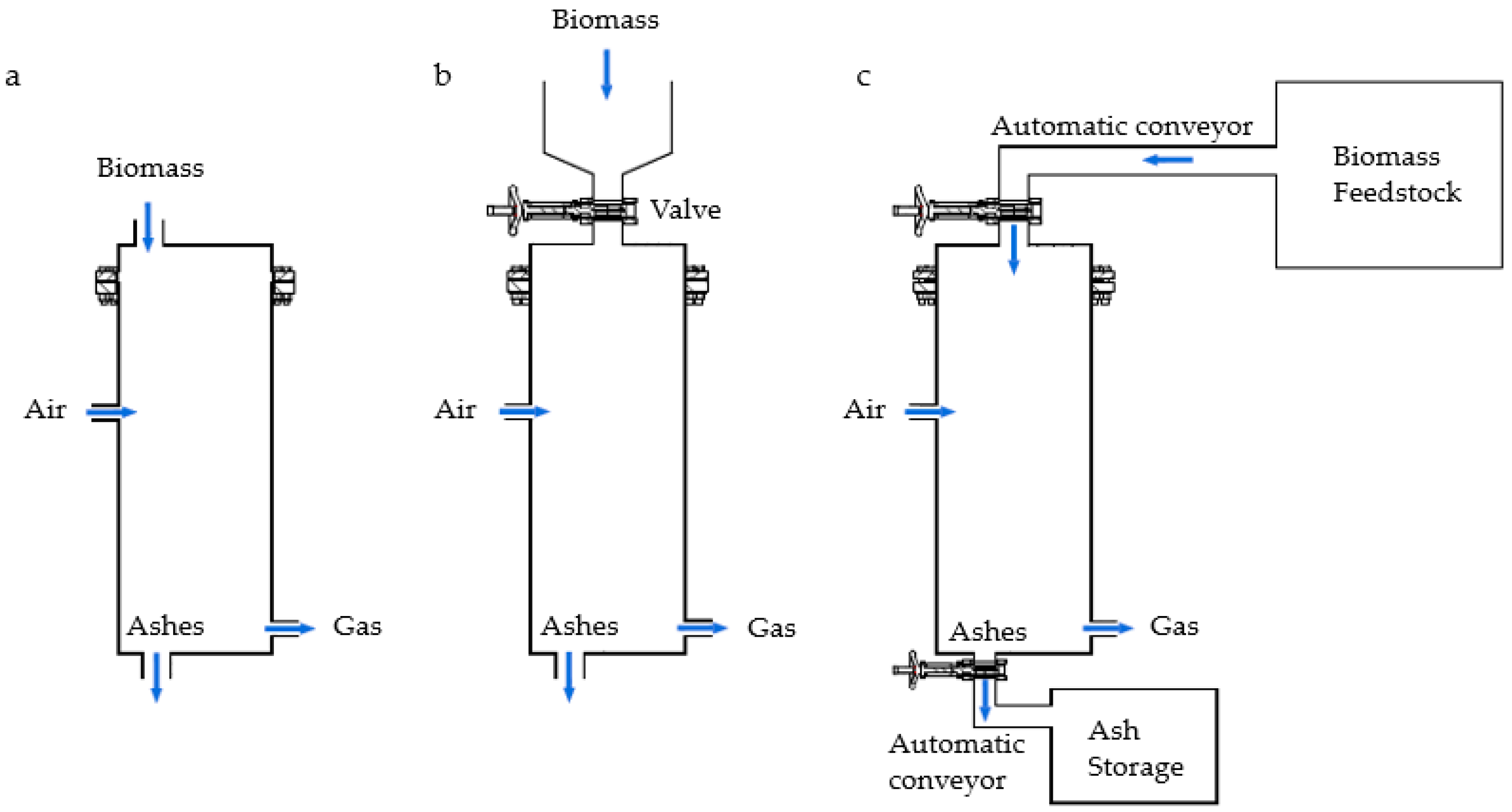
Between the two possible supplying solutions, there is the semi-batch feeding mode which is defined by an initial feeding at the start of gasification, then by the addition of biomass into the reactor at a few regular time intervals. In this mode, ashes are not emptied out while the gasifier is working, they are removed once the gasification process is ended. The semi-batch supply of biomass includes auxiliaries which are, in addition to the gasification reactor, a biomass container fitted with a tight lid. This container is connected to the top of the reactor. The size and shape of the biomass particles are important in determining the difficulty associated with their feeding into the reactor. In this configuration, an operator manually puts the biomass into the container and opens the connecting section to allow the biomass to flow into the reactor. The aim of this feeding system is mainly to increase the gasification time compared to a conventional batch process and at the same time having a simplified system compared to continuous supply. The three methods are represented in Figure 3.
The evaluation of these three fuel supply options and the choice of one of them are based on the properties of the fuel, on the type of reactor, on the size of the installation and also on the properties of the expected syngas.
2.4.2. The Gasification Agent Supply Mode
The gasification agent can be supplied in two main ways into a gasifier: by aspiration with an induced draft fan or by insufflation with a forced draft fan. Different authors have worked on these two configurations. For example, Rakotosaona et al. worked on a gasifier design with the particularity of operating by aspiration. A centrifugal fan allows the air to be drawn into the reactor and at the same time to evacuate the syngas downstream [26]. Nevertheless, the gas aspiration downstream of the reactor remains relatively less widespread in gasification due to the larger mass flow rate, the risk of fouling, etc. According to the main objectives to reach, these two methods of air introduction will be considered to deduce the best option for the solution.
2.4.3. The Arrangement of the Flows in the Reactor
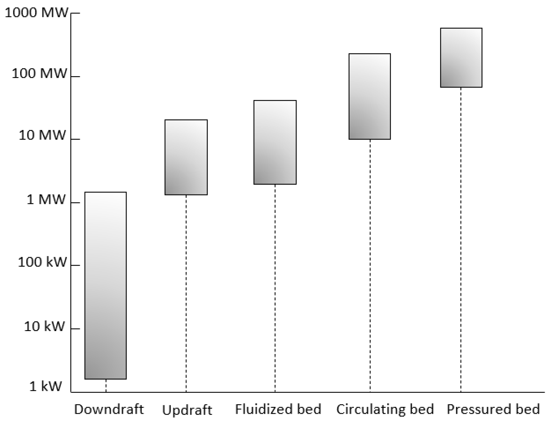
The arrangement of the flows in the reactor defines at the same time the type of reactor. Many types of reactor exist depending on the power range; see Figure 4. For this study, two types of reactor well-suited for electricity production at small scale were considered: the downdraft fixed bed and the bubbling fluidised bed [25,27]. In the following, these two reactors will be called fixed bed and fluidised bed, respectively. The differences between these two types of reactors are, firstly, the velocity of the gases in the reactor. In a fixed bed the velocity is low, while being much larger in a fluidised bed [28]. In addition, in the fixed-bed reactor there is a stratification of the process along the reactor. In fluidised bed, the different zones cannot be distinguished and the temperature is uniform throughout the bed.
The targeted objective, the production of electricity by burning the syngas in an internal combustion engine, permits us to limit the choice of the type of reactor to the solutions proposed above. The producer gas specifications for internal combustion engines are listed in Table 3 below [29,30].
The downdraft fixed bed was chosen, among other types of fixed beds, because it is the most suitable for this application [31,32]. In Table 4, the tar yield according to the type of gasifier is reported. In the downdraft fixed bed, the tar fraction in the raw gas (i.e., before the gas conditioning unit) is very low, from 0.01 to 6 g/Nm3. On the contrary, the updraft fixed bed produces a syngas with larger tar concentrations of 10 to 150 g/Nm3, which cannot be burnt in an engine without an extensive conditioning producing effluents [33,34]. Indeed, most internal combustion engines admit syngas with a maximum tar rate of much less than 1 g/Nm3 [35].
There are several types of fluidised bed reactors: bubbling fluidised beds (here called fluidised bed), circulating beds and pressured beds [36]. Only the bubbling fluidised bed is considered here. While it is usually suited for much larger powers [37]—see Figure 4—it has been included in the design phase to explore the opportunity of such a reactor at small scale in the very specific West-African conditions. Therefore, even if based solely on the information in Figure 4, the downdraft fixed bed is the best gasifier considering the size of the power plant, the bubbling fluidised bed can be a solution in the design morphological chart for its easier local manufacture, its suitability for rice husk fuel and its moderate gas-cleaning step.
2.5. Evaluating the Alternatives
Combinations of the three essential functions have been made, leading to nine possible options for the reactor technology. Thus, each reactor is a combination of the technological options, with respect to the mode of biomass supply (batch, semi-batch or continuous supply), air supply (aspiration or insufflation) and the type of the bed (fixed or fluidised bed), see Table 5. The combination of aspiration and fluidised bed is excluded for feasibility reasons.
The comparison of all these technologies is carried out based on the ten main objectives previously defined in Section 2.1. Each technology was assigned an impact score for each of the ten objectives. The weighted sum of the scores given to the reactor for achieving the different objectives allows us to identify the best combination.
The score of each technology is performed on a scale of −4 to 4. However, one technology, the batch fixed bed with insufflation, has been designated as a reference technology, with the score zero for all objectives. Indeed, it is easier to evaluate the performance of the different designs on a relative basis than on an absolute one.
3. Results
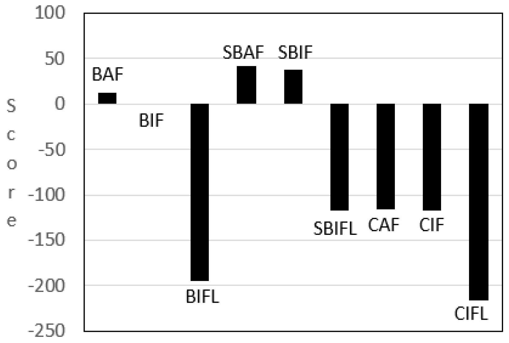
In Table 6, the designs are scored in the morphological chart. Thus, according to the methodology, scores are assigned according to an assessment given by relating each gasifier model to the objectives established in the study. The SBAF, the SBIF and the BAF have a score of +42, +38 and +12, respectively. These three reactors are better scored than the reference reactor BIF, which scored at zero by definition. The SBIF scores better than the BIF mainly because of the good efficiency of the reactor and the better gas quality. As said previously in Section 2.4.1, the batch supply mode has transient with low gas quality at each feed.
The SBAF and the BAF good scores are mostly due to the fact that the security of installation is better because the air aspiration permits us to avoid gas leaks that can be dangerous for human health by poisoning [38]. They are also more environmentally sustainable than the BIF because of the low gas leaks during human actions. The major negative points of these two reactors (SBAF and BAF) are due to the aspiration. They are less-resistant devices because syngas aspiration can damage the blower by the remaining heat of the exiting gas, even after the gas cleaning and cooling, or the tar deposits and their maintenance is laborious. The mode of introducing the biomass into the gasifier by semi-batch feeding (such as in SBAF and SBIF gasifiers) takes precedence over the batch and continuous modes. The semi-batch mode is better than the continuous mode because it is a less complex system to implement locally compared to the continuous system. The semi-batch is also better than the batch feeding because it allows a better gas quality, even if, for the first objective, the semi-batch supply system is more difficult to manufacture locally than the batch one. For the resistance and the multifuel eligibility, the semi batch is less advantageous because the feeding mechanism is more sensitive to biomass granulometry. However, the semi batch allows us to produce less unburnt by-products, and thus has a better conversion efficiency.
The fixed-bed reactor outweighs the fluidised bed one because the downdraft fixed bed produces a lower yield of tar and particles in the syngas than the fluidised bed [39]. The mode of air supply by aspiration is preferable to the insufflation because it mainly permits us to avoid gas leaks and improve security.
The reactors BIFL, SBIFL, CAF, CIF and CIFL score less than the reference gasifier BIF. The defined objectives are hardly reached with them. The BIFL is one of the worst reactors compared to the BIF; in fact, the fluidised bed is more difficult to implement locally, and it results in a bad gas quality due to particles and the tar level in the syngas. Additionally, the SBIFL and CIFL score lower because the fluidised bed reduces the multifuel eligibility as most of the time a pretreatment of the biomass (mostly a size reduction) is necessary for the bed fluidisation. The other objectives that are hardly reached with this type of gasifier are the local manufacturing, the resistance of installation and the maintenance of the devices due to the continuous mechanism or the fluidised bed implementation. In addition, the security of the installations is more sensitive to gas leaks because of the air blowing. The CIF and CAF reactors have bad scores caused mainly by the continuous fuel supply. Even if the CAF reactor is more secure thanks to the aspiration of air and the gas quality is better for this type of gasifiers (CIF and CAF) thanks to the continuous feeding [40]. The continuous mechanism of the CIF and CAF reactors is difficult to manufacture locally and its maintenance is also more difficult. However, one of the positive points is that it produces a good syngas quality and the conversion of the fuel is also better in continuous systems (of CIFL, CAF and CIF) because there are few solids at the end and less heat losses [24].
After comparison of the nine possible gasifiers defined by the morphological chart in Section 2.5, the Semi-Batch Fixed-bed reactor with Aspiration (SBAF) is the most in line with the established objectives; see Figure 5.
3.1. Reactor Configuration
The detailed design of a downdraft fixed bed gasifier requires several additional specifications. In fact, there are basically two types of downdraft fixed-bed reactors: the stratified reactor and the throated reactor. The stratified reactor has the shape of a cylinder, while the throated reactor, also called Imbert from the name of its inventor, has a constriction generally at one-third of its height from the bottom grid. The presence of a throat where the air is introduced promotes the oxidant/fuel mixture, on the one hand, and prevents the occurrence of relatively cold zones through which tars could pass without being cracked, on the other hand [41,42].
In the stratified downdraft reactor, the air is generally introduced at the same time as the biomass from the top of the reactor. In this case, the oxidation and pyrolysis phases move together in a flame front. This reduces the restrictions on the type and size of the fuel, but the concentration of tar in the produced gas is higher [43]. However, to decrease the production of tars, a double air injection can be carried out on the reactor, one at the top and one where the oxidation should take place. This sets the location of the three main reactions in the gasifier, pyrolysis, oxidation and reduction, helping to reduce the levels of tar [43,44].
In order to determine the most suitable type of reactor, an assessment of four different prototypes has been carried out according to the objectives. These prototypes are: an Imbert reactor with an air inlet, an Imbert reactor with double air injection; a stratified reactor with an air inlet and a stratified reactor with double air injection. To decide on the best configuration of the downdraft gasifier, these four reactors have been scored according to the ten defined objectives and the most suitable is the downdraft stratified reactor with double air injection. This choice was made mainly because the stratified gasifier is easier to manufacture locally, and the double air injection allows better gas quality.
3.2. Detailed Design of the Gasifier
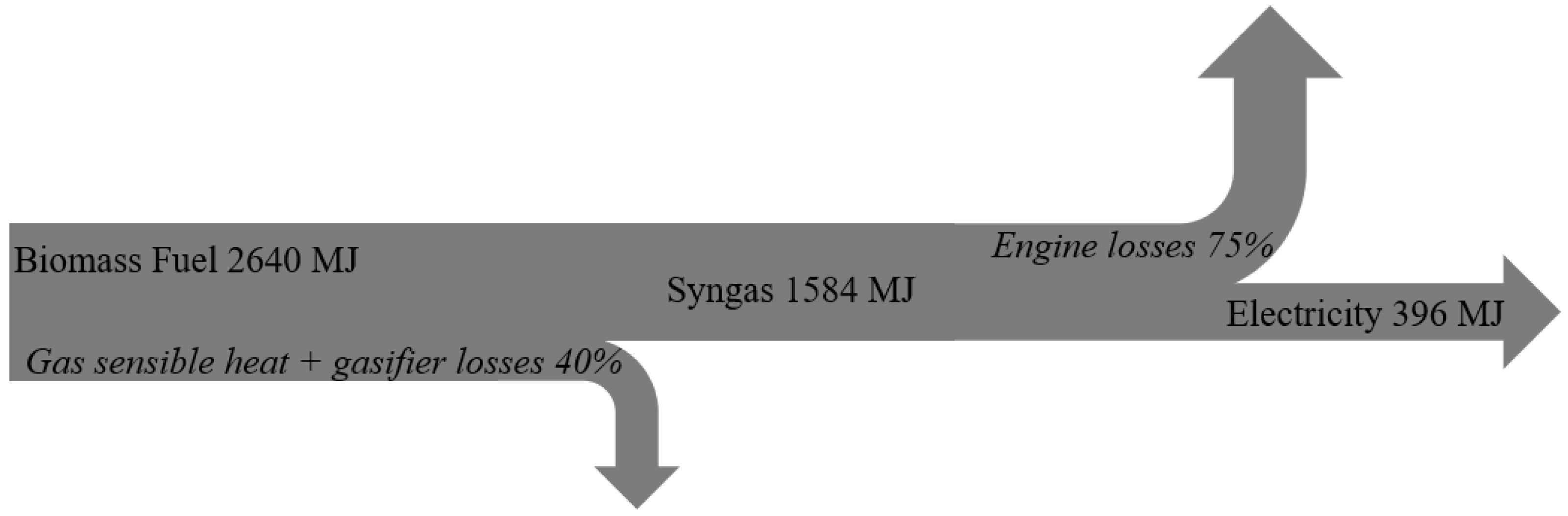
Equations (3)–(5) were used to calculate the power of the syngas based on the lower heating value, the specific gasification rate (SGR) and the fuel consumption rate. The required power output, Q (kWth), is determined using Equation (3); where, (kWh), is the energy of the syngas based on the industrial unit needs and t (h) is the running time. Knowing the rice husker energy consumption per day, the engine efficiency is used to calculate the energy of the syngas fed to the engine (see Figure 6). Then, the biomass energy is deduced by applying the gasifier energy balance. This biomass energy corresponds, as previously determined in Section 2.3, to 200 kg/day of rice husk fuel based on the lower heating value of rice husk.
The specific gasification rate (SGR) is defined as the fuel consumption reported in the reactor section, and is expressed in Equation (4), where, (kg/h) is the fuel consumption rate and S (m) is the cross-sectional area of the reactor. The fuel consumption rate was determined using Equation (5); where, (kJ/kg) is the calorific value of biomass and (%) is the performance of the gasifier.
Table 7 sums up the main characteristics of the designed reactor:
3.3. Design Plans of the Gasifier
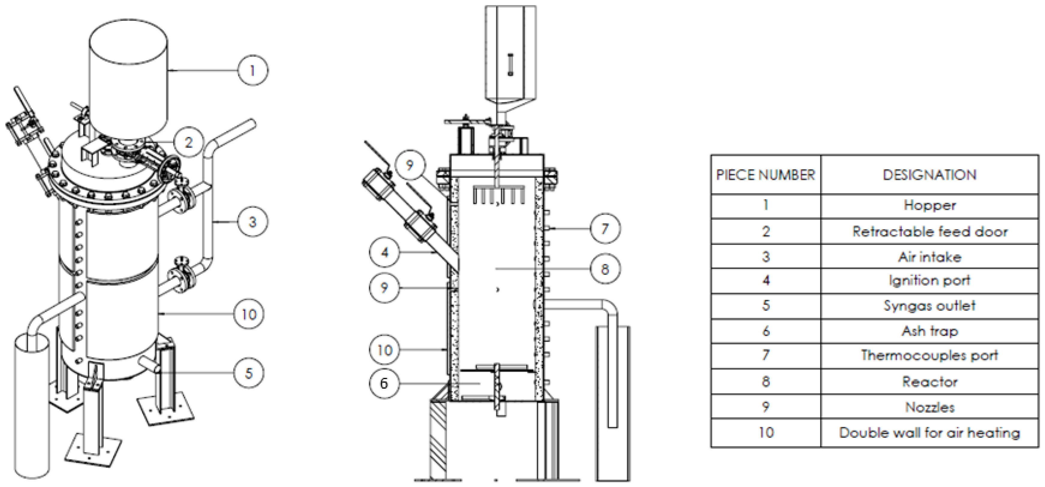
The design methodology and the sizing have permitted us to obtain a final design converted into technical blueprints for the local manufacturing of a prototype. A sketch of the design is presented in Figure 7. The biomass is supplied in the hopper, then the operator opens the valve to let the biomass drop into the reactor. The air is split into two streams. The air passes through the pipes and enters in the double walls to be heated by the contact with the hot reactor walls, to finally arrive at the nozzles. The gas is recovered at the bottom of the gasifier. Ashes are removed at the end of the gasification process after cooling down by opening the ash trap. Next to the gasifier, there is a gas cleaning and cooling unit. This unit already exists and was not part of the design methodology, thus, the designed gasifier has been connected to it. The cleaning and cooling unit is composed of a cyclone, a heat exchanger to cool the gas and a rice husk filter with oil bubbler for tar removal. The product gas cleaning unit allows to remove particles and tars from gas.
4. Conclusions
This paper reports a methodology for designing a gasification reactor according to Cross’ approach. The definition of the objectives, the functional analysis, the specification of performances, the generation of solutions as well as their evaluation were the main steps to arrive to the reactor plans. Based on this approach, the Semi-Batch, Fixed-bed reactor with air Aspiration (SBAF) reactor was found to be the most suited to the design requirements and to the defined objectives, such as the local manufacturing, the security of installation or the gas quality. The SBAF consists in a downdraft fixed-bed reactor, with an introduction of air by suction and a semi-batch fuel supply. For this reactor, the description of the equipment and the completion of the technical plans were the last deliverables of the methodology. The designed reactor has an average consumption of biomass of 20.38 kg/h with a SGR of 101.9 kg/m2h. The syngas output power is 44 kWth.
Author Contributions
Conceptualisation, L.Z., B.H. and H.J.; methodology, L.Z., S.d.S.S., B.H., Y.C. and H.J.; validation, L.Z. and H.J.; writing—original draft preparation, L.Z.; writing—review and editing, H.J.; supervision, Y.C. and H.J.; project administration, S.d.S.S. and H.J. All authors have read and agreed to the published version of the manuscript.
Funding
This study was funded by the “Académie de la Recherche et de l’Enseignement Supérieur” of the “Fédération Wallonie-Bruxelles (Belgium)-Commission de la Coopération au Développement” (ARES-CCD).
Institutional Review Board Statement
Not applicable.
Informed Consent Statement
Not applicable.
Data Availability Statement
Not applicable.
Acknowledgments
The authors would like to express gratitude to ARES-CCD for funding this study as part of an international research and development project “Contribution à la satisfaction des besoins énergétiques en milieu rural par gazéification de résidus agricoles (PRD Gascal)”.
Conflicts of Interest
The authors declare no conflict of interest. The funders had no role in the design of the study; in the collection, analyses or interpretation of data; in the writing of the manuscript or in the decision to publish the results.
References
- IEA. World Energy Outlook 2019; IEA: Paris, France, 2019. [Google Scholar]
- Walker, S.B.; van Lanen, D.; Mukherjee, U.; Fowler, M. Greenhouse gas emissions reductions from applications of Power-to-Gas in power generation. Sustain. Energy Technol. Assess. 2017, 20, 25–32. [Google Scholar] [CrossRef]
- IRENA. Africa 2030: Roadmap for a Renewable Energy Future. IRENA, Abu Dhabi. 2015. Available online: www.irena.org/remap (accessed on 15 May 2021).
- Adkins, E.; Oppelstrup, K.; Modi, V. Rural household energy consumption in the millennium villages in Sub-Saharan Africa. Energy Sustain. Dev. 2012, 16, 249–259. [Google Scholar] [CrossRef]
- Cantoni, R.; Svenningsen, L.S.; Sanfo, S. Unattainable proximity: Solar power and peri-urbanity in central Burkina Faso. Energy Policy 2021, 150, 112127. [Google Scholar] [CrossRef]
- Herrera, I.; Rodríguez-Serrano, I.; Lechón, Y.; Oliveira, A.; Krüger, D.; Bouden, C. Sustainability assessment of a hybrid CSP/biomass. Results of a prototype plant in Tunisia. Sustain. Energy Technol. Assess. 2020, 42, 100862. [Google Scholar] [CrossRef]
- N’Tsoukpoe, K.E.; Azoumah, K.Y.; Ramde, E.; Fiagbe, A.Y.; Neveu, P.; Py, X.; Gaye, M.; Jourdan, A. Integrated design and construction of a micro-central tower power plant. Energy Sustain. Dev. 2016, 31, 1–13. [Google Scholar] [CrossRef]
- Zoungrana, L.; Sidibe, S.D.S.; Richardson, Y.; Coulibaly, Y. Review of gasification modelling and equilibrium model implementation to predict rice husk syngas composition. J. Phys. Soaphys 2019, 1, C19A12-1–C19A12-7. [Google Scholar] [CrossRef]
- Dasappa, S. Potential of biomass energy for electricity generation in sub-Saharan Africa. Energy Sustain. Dev. 2011, 15, 203–213. [Google Scholar] [CrossRef]
- Kannengiesser, U.; Gero, J.S. Can Pahl and Beitz’ systematic approach be a predictive model of designing? Des. Sci. 2017, 3, E24. [Google Scholar] [CrossRef] [Green Version]
- Maussang, N. Méthodologie de Conception des Systèmes Produits-Services; Sciences de L’ingénieur [Physics]; Institut National Polytechnique de Grenoble—INPG: Grenoble, France, 2008. [Google Scholar]
- Cross, N. Engineering Design Methods STRATEGIES for Product Design; John Wiley & Sons Ltd.: Chichester, UK, 2000. [Google Scholar]
- Blomberg, T. What are the right test conditions for the simulation of high temperature alkali corrosion in biomass combustion? In Novel Approaches to Improving High Temperature Corrosion Resistance; Woodhead Publishing: Cambridge, UK, 2008; pp. 501–513. [Google Scholar] [CrossRef]
- Khanna, A.S. High Temperature Oxidation. In Handbook of Environmental Degradation of Materials; Elsevier: Amsterdam, Netherlands, 2012; pp. 127–194. [Google Scholar] [CrossRef]
- Huang, Y.; Zhang, L.; Duan, F. Investigation on thermal behavior and sulfur release characteristics from rice husk and bituminous coal co-firing under O2/CO 2 atmosphere: Co-combustion of Rice Husk and Bituminous Coal. Asia-Pac. J. Chem. Eng. 2016, 11, 51–59. [Google Scholar] [CrossRef]
- Dogru, M.; Midilli, A.; Howarth, C.R. Gasification of sewage sludge using a throated downdraft gasifier and uncertainty analysis. Fuel Process. Technol. 2002, 75, 55–82. [Google Scholar] [CrossRef]
- Dasappa, S.; Sridhar, H.V. Performance of a diesel engine in a dual fuel mode using producer gas for electricity power generation. Int. J. Sustain. Energy 2013, 32, 153–168. [Google Scholar] [CrossRef]
- Gao, X.; Xu, F.; Bao, F.; Tu, C.; Zhang, Y.; Wang, Y.; Yang, Y.; Li, B. Simulation and optimization of rice husk gasification using intrinsic reaction rate based CFD model. Renew. Energy 2019, 139, 611–620. [Google Scholar] [CrossRef]
- Susastriawan, A.A.P.; Saptoadi, H.; Purnomo. Comparison of the gasification performance in the downdraft fixed-bed gasifier fed by different feedstocks: Rice husk, sawdust, and their mixture. Sustain. Energy Technol. Assess. 2019, 34, 27–34. [Google Scholar] [CrossRef]
- Salisu, J.; Gao, N.; Quan, C. Techno-economic assessment of co-gasification of rice husk and plastic waste as off-grid power source for small scale rice milling in Nigeria-an Aspen plus model. J. Anal. Appl. Pyrolysis 2021, 158, 105157. [Google Scholar] [CrossRef]
- Casaca, C.; Costa, M. The Effectiveness of Reburning Using Rice Husk as Secondary Fuel for NOX Reduction in a Furnace. Combust. Sci. Technol. 2005, 177, 539–557. [Google Scholar] [CrossRef]
- De Filippis, P.; Scarsella, M.; Verdone, N.; Carnevale, G.B. Batch Waste Gasification Technology: Characteristics and Perspectives; WIT Press: Southampton, UK, 2010; pp. 3–10. [Google Scholar] [CrossRef] [Green Version]
- Manisha, P. Pyrolysis and Gasification of Biomass and Acid Hydrolysis Residues. Ph.D. Thesis, Aston University, Birmingham, UK, 2013. [Google Scholar]
- Daouk, E. Etudes Expérimentale et Numérique de la Pyrolyse Oxydante de la Biomasse en Lit Fixe. Ph.D. Thesis, Génie des procédés, Ecole des Mines de Nantes, Nantes, France, 2015. [Google Scholar]
- Bellouard, Q. Valorisation de Biomasse en Vecteur Énergétique par Voie Thermochimique Solaire. Ph.D. Thesis, Génie des procédés, Université de Perpignan Via Domita, Perpignan, France, 2017. [Google Scholar]
- Rakotosaona, R.; Rakotomalala, R.M.; de Ramaroson, J.D.; Andrianary, P. Conception et Réalisation d’un Gazogène Downdraft à Usage Domestique: Application à la Gazéification des Éclats D’eucalyptus; Universite d’Antananarivo: Antananarivo, Madagascar, 2012. [Google Scholar]
- Ndindeng, S.A.; Wopereis, M.; Sanyang, S.; Futakuchi, K. Evaluation of fan-assisted rice husk fuelled gasifier cookstoves for application in sub-Sahara Africa. Renew. Energy 2019, 139, 924–935. [Google Scholar] [CrossRef]
- Cluet, B. Evaluation de la Ségrégation de la Biomasse dans un Lit Fluidisé et Modélisation Globale du Procédé de Gazéification. Ph.D. Dissertation, Mécanique et Energétique, Universite de Lorraine, Nancy, France, 2014. [Google Scholar]
- Laurence, L.C.; Ashenafi, D. Syngas treatment unit for small scale gasification application to IC engine gas quality requirement. J. Appl. Fluid Mech. 2011, 5, 95–103. [Google Scholar]
- Basu, P. Biomass Gasification, Pyrolysis and Torrefaction. Practical Design and Theory, 2nd ed.; Academic Press: Boston, MA, USA, 2013. [Google Scholar]
- Commeh, M.K.; Kemausuor, F.; Badger, E.N.; Osei, I. Experimental study of ferrocement downdraft gasifier engine system using different biomass feedstocks in Ghana. Sustain. Energy Technol. Assess. 2019, 31, 124–131. [Google Scholar] [CrossRef]
- Indrawan, N.; Simkins, B.; Kumar, A.; Huhnke, R.L. Economics of Distributed Power Generation via Gasification of Biomass and Municipal Solid Waste. Energies 2020, 13, 3703. [Google Scholar] [CrossRef]
- Basu, P. Biomass Gasification and Pyrolysis Practical Design and Theory; Academic Press: Cambridge, MA, USA, 2010. [Google Scholar]
- Berger, B. Experimental and Numerical Investigation of a Two-Stage Downdraft Biomass Gasification Process. Ph.D. Thesis, Université catholique de Louvain, Louvain-la-Neuve, Belgium, 2018. [Google Scholar]
- Bhaduri, S.; Berger, B.; Pochet, M.; Jeanmart, H.; Contino, F. HCCI engine operated with unscrubbed biomass syngas. Fuel Process. Technol. 2017, 157, 52–58. [Google Scholar] [CrossRef]
- Breault, R.W. Gasification Processes Old and New: A Basic Review of the Major Technologies. Energies 2010, 3, 216–240. [Google Scholar] [CrossRef] [Green Version]
- Pecate, S. Gazéification de la Biomasse en Lit Fluidisé Dense et Circulant entre 750 et 850 °C: Étude Hydrodynamique et Réactive. Génie des Procédés et de l’Environnement. Ph.D. Dissertation, Université de Toulouse, Toulouse, France, 2017. [Google Scholar]
- Reed, T.B.; Das, A. Handbook of Biomass Downdraft Gasifier Engine Systems; SERI: Golden, CO, USA, 1988. [Google Scholar]
- UNIDO; USPCAS-E National University of Sciences and Technology. Biomass Gasification Systems Training Manual; National University of Sciences and Technology: Islamabad, Pakistan, 2016. [Google Scholar]
- Duku, M.H.; Gu, S.; Hagan, E.B. A comprehensive review of biomass resources and biofuels potential in Ghana. Renew. Sustain. Energy Rev. 2011, 15, 404–415. [Google Scholar] [CrossRef]
- Bassil, G. Gazéification de la Biomasse: Élimination des Goudrons par Lavage, Étude Expérimentale et Modélisation. Doctoral Dissertation, Université Claude Bernard-Lyon I, Lyon, France, 2012. [Google Scholar]
- Sansaniwal, S.K.; Pal, K.; Rosen, M.A.; Tyagi, S.K. Recent advances in the development of biomass gasification technology: A comprehensive review. Renew. Sustain. Energy Rev. 2017, 72, 363–384. [Google Scholar] [CrossRef]
- Gerun, Luc. Etude Numérique et Expérimentale de la Valorisation Énergétique de la Biomasse par Gazéification. Ph.D. Thesis, Université de Nantes, Nantes, France, 2007.
- Susastriawan, A.A.P.; Saptoadi, H.; Purnomo. Design and experimental study of pilot scale throat-less downdraft gasifier fed by rice husk and wood sawdust. Int. J. Sustain. Energy 2018, 37, 873–885. [Google Scholar] [CrossRef]
Figure 1.
The seven stages of the design process, as proposed by Cross used to design the gasifier. Adapted from [12], with permission from publisher John Wiley and Sons, 2021.
Figure 1.
The seven stages of the design process, as proposed by Cross used to design the gasifier. Adapted from [12], with permission from publisher John Wiley and Sons, 2021.

Figure 2.
The functional analysis of the gasifier with the main gasification functions, the secondary treatment functions and the product flows between the functions.
Figure 2.
The functional analysis of the gasifier with the main gasification functions, the secondary treatment functions and the product flows between the functions.

Figure 3.
Representation of the three modes of biomass feeding (a) batch; (b) semi batch and (c) continuous.
Figure 3.
Representation of the three modes of biomass feeding (a) batch; (b) semi batch and (c) continuous.

Figure 4.
Types of gasifier according to their output power.

Figure 5.
Global scores of the nine designs relative to the BIF design.

Figure 6.
The energy conversion from biomass to electricity use, with the gasification yield estimated at 60% of efficiency (equivalent to 40% of losses) and the engine yield taken at 25% of efficiency (equivalent to 75% losses).
Figure 6.
The energy conversion from biomass to electricity use, with the gasification yield estimated at 60% of efficiency (equivalent to 40% of losses) and the engine yield taken at 25% of efficiency (equivalent to 75% losses).

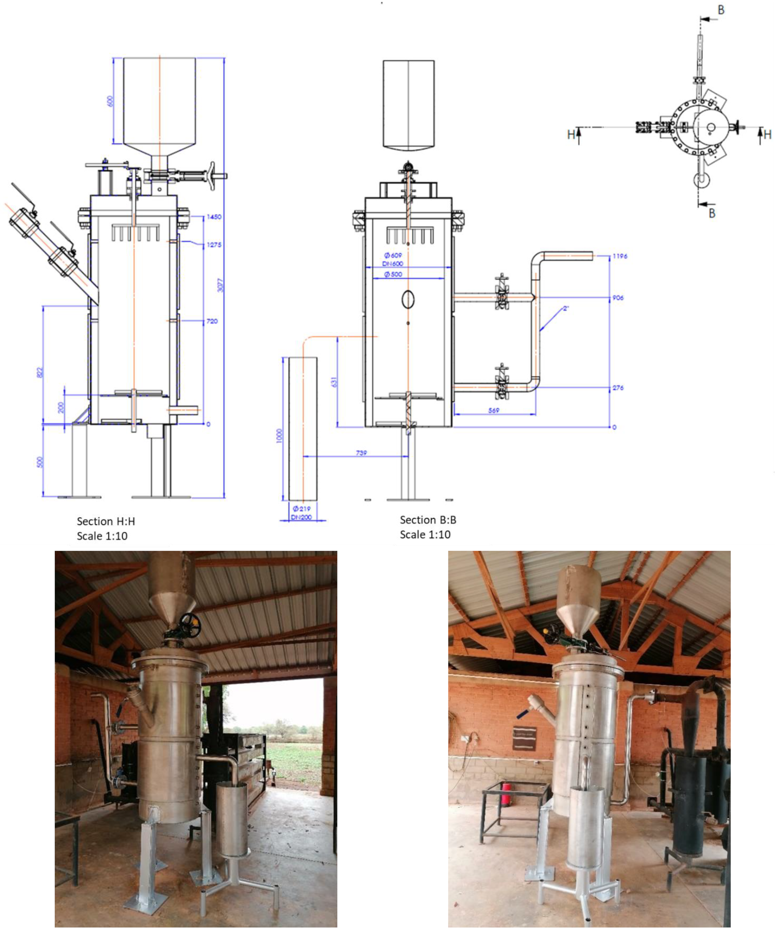
Figure 7.
The technical plans of the selected gasifier and the manufactured prototype.


Table 1.
Real and relative weights of the main objectives and subobjectives of the design of a gasifier for application in West Africa.
Table 1.
Real and relative weights of the main objectives and subobjectives of the design of a gasifier for application in West Africa.
| Objectives | Weights | Subobjectives | Real Weights | Relative Weights |
|---|---|---|---|---|
| Local manufacturing | 13 | Local material | 6.5 | 50 |
| Local labour | 6.5 | 50 | ||
| Safe installation | 13 | Safe for user | 6.5 | 50 |
| Isolated reactor | 6.5 | 50 | ||
| Gas quality | 12 | Fuel in engine | 10.8 | 90 |
| Flare combustion | 1.2 | 10 | ||
| Resistant device | 12 | Strong platform | 6 | 50 |
| Resistant materials | 6 | 50 | ||
| Accessible use for local users | 10 | Easy ignition and extinction | 2.5 | 25 |
| Easy control of instrumentation | 2.5 | 25 | ||
| Easy fuel supply and ash removal | 2.5 | 25 | ||
| Intuitive device | 2.5 | 25 | ||
| Maximum valorisation of the fuels | 9 | Good syngas | 4.5 | 50 |
| Least heat losses | 1.8 | 20 | ||
| Good conversion of biomass | 2.7 | 30 | ||
| Environmentally sustainable | 9 | Efficient electric consumption | 1.8 | 20 |
| Least use of water | 0.9 | 10 | ||
| Conform to the standard of release on soil | 2.25 | 25 | ||
| Conform to the standard of release into the atmosphere | 2.25 | 25 | ||
| Quietly noisy | 0.45 | 5 | ||
| No characteristic odour | 1.35 | 15 | ||
| Easy maintenance | 9 | Long maintenance frequency | 0.9 | 10 |
| No requirement of specific qualification | 8.1 | 90 | ||
| Multi fuels | 7 | Local biomass | 7 | 100 |
| Capacity | 6 | Satisfies the daily energy need | 6 | 100 |
Table 2.
Physicochemical properties of rice husk considered for the design of the gasifier (data from [21]).
Table 2.
Physicochemical properties of rice husk considered for the design of the gasifier (data from [21]).
| Proximate Analysis (wt %) | Ultimate Analysis (wt %) | ||
|---|---|---|---|
| Moisture | 9.8 | C | 38.8 |
| Volatiles | 59.9 | H | 4.6 |
| Fixed carbon | 14.7 | N | 1.3 |
| Ash | 15.6 | S | 0.3 |
| O | 29.6 | ||
| Lower heating value (MJ/kg) | 13.88 | ||
| Component | Unit | IC Engine |
|---|---|---|
| Particles | mg/Nm3 | 30 |
| Particles size | μm | <10 |
| Tar content | mg/Nm3 | 50–100 |
| Gas heating value | kJ/Nm3 | >2500 |
Table 4.
Tar yield according to the type of gasifier [29].
Table 4.
Tar yield according to the type of gasifier [29].
| Downdraft | Updraft | Bubbling Bed | Circulating Bed | |
|---|---|---|---|---|
| Mean tar yield (g/Nm3) | 0.5 | 50 | 12 | 8 |
Table 5.
The morphological chart of the designs.
| Batch | Semi Batch | Continuous | ||||||
|---|---|---|---|---|---|---|---|---|
| Aspiration | Insufflation | Aspiration | Insufflation | Aspiration | Insufflation | |||
| Fixed | Fixed | Fluidised | Fixed | Fixed | Fluidised | Fixed | Fixed | Fluidised |
| BAF | BIF | BIFL | SBAF | SBIF | SBIFL | CAF | CIF | CIFL 1 |
1 Batch (B), semi-batch (SB) and continuous (C) biomass supply; aspiration (A), and insufflation (I) air supply; fixed (F) and fluidised bed (FL) types of gasifier.
Table 6.
Comparative scores given to the different reactors for the different objective. Scores are relative to the BIF case.
Table 6.
Comparative scores given to the different reactors for the different objective. Scores are relative to the BIF case.
| Objectives | Weight | Batch (6 Daily) | Semi Batch | Continuous | |||||||||
|---|---|---|---|---|---|---|---|---|---|---|---|---|---|
| Aspiration | Insufflation | Aspiration | Insufflation | Aspiration | Insufflation | ||||||||
| Fixed | Fluid. | Fixed | Fluid. | Fixed | Fluid. | Fixed | Fluid. | Fixed | Fluid. | Fixed | Fluid. | ||
| BAF | BIF | BIFL | SBAF | SBIF | SBIFL | CAF | CIF | CIFL | |||||
| Local manufacturing | 13 | 0 | 0 | −2 | −1 | −1 | −3 | −4 | −4 | −4 | |||
| Secure installation | 13 | 3 | 0 | −2 | 2 | −1 | −2 | 1 | −3 | −4 | |||
| Gas quality | 12 | −1 | 0 | −2 | 1 | 2 | 1 | 3 | 4 | 3 | |||
| Resistant device | 12 | −1 | 0 | −2 | −2 | −1 | −3 | −4 | −3 | −4 | |||
| Use accessible to all | 10 | 0 | 0 | −2 | 1 | 1 | −1 | −2 | −2 | −4 | |||
| Maximum recovery of fuels | 9 | 0 | 0 | −2 | 1.44 | 1.44 | 1 | 0.99 | 0.99 | 0.5 | |||
| Environmentally sustainable | 9 | 1.575 | 0 | −1 | 0.45 | 0.675 | −1 | −2.475 | −0.45 | −2 | |||
| Easy maintenance | 9 | −2 | 0 | −3 | 1 | 2 | −1 | −4 | −3 | −4 | |||
| Eligible multi-fuels | 7 | 0 | 0 | −3 | −1 | −1 | −3 | −2 | −2 | −4 | |||
| Capacity | 6 | 0 | 0 | 0 | 2 | 2 | 2 | 3 | 3 | 3 | |||
| TOTAL | 100 | 12 | 0 | −195 | 42 | 38 | −117 | −116 | −117 | −216 | |||
Table 7.
Specific design characteristics of the semi-batch fixed downdraft gasifier.
| Data | Units | Reactor |
|---|---|---|
| Q [kWth] | [kWLHV] | 44 |
| Average biomass consumption | [kg/h] | 20.38 |
| Average air flow | [kg/h] | 28.8 |
| SGR | [kg/m2/h] | 101.9 |
| Reactor section | [m2] | 0.2 |
| Reactor height | [m] | 1.7 |
Publisher’s Note: MDPI stays neutral with regard to jurisdictional claims in published maps and institutional affiliations. |
© 2021 by the authors. Licensee MDPI, Basel, Switzerland. This article is an open access article distributed under the terms and conditions of the Creative Commons Attribution (CC BY) license (https://creativecommons.org/licenses/by/4.0/).
Share and Cite
MDPI and ACS Style
Zoungrana, L.; Sidibé, S.d.S.; Herman, B.; Coulibaly, Y.; Jeanmart, H. Design of a Gasification Reactor for Manufacturing and Operation in West Africa. Designs 2021, 5, 76. https://doi.org/10.3390/designs5040076
AMA Style
Zoungrana L, Sidibé SdS, Herman B, Coulibaly Y, Jeanmart H. Design of a Gasification Reactor for Manufacturing and Operation in West Africa. Designs. 2021; 5(4):76. https://doi.org/10.3390/designs5040076
Chicago/Turabian StyleZoungrana, Laetitia, Sayon dit Sadio Sidibé, Benoît Herman, Yézouma Coulibaly, and Hervé Jeanmart. 2021. "Design of a Gasification Reactor for Manufacturing and Operation in West Africa" Designs 5, no. 4: 76. https://doi.org/10.3390/designs5040076