
Adaptive Control of Energy Storage Systems for Real-Time Power Mediation Based on Energy on Demand System

1
School of Information Science, Japan Advanced Institute of Science and Technology, 1-1 Asahidai, Nomi City 923-1292, Ishikawa, Japan
2
Department of Computer Science, Kyoto Tachibana University, Kyoto 607-8175, Japan
*
Author to whom correspondence should be addressed.
Designs 2022, 6(5), 97; https://doi.org/10.3390/designs6050097
Submission received: 21 August 2022
/
Revised: 12 October 2022
/
Accepted: 14 October 2022
/
Published: 19 October 2022
(This article belongs to the Section Energy System Design)
Abstract
:The concept of i-Energy as a new smart demand-side energy management system is proposed, which can realize the versatile and efficient control of e-power flows between distributed generators, numerous appliances, and energy storage systems in the home domain, factories, offices, and local communities. The Energy on Demand (EoD) system is proposed, which is the automatic power control and management system that supplies power to home appliances based on the power demand requests issued from the home appliances. The EoD system can guarantee the reduction in total power consumption by implementing a ceiling control while keeping the quality of life (QoL) of the home user considering the limitation of power supply. This paper proposes an adaptive battery storage management and control method based on the EoD system, which we call the “storage-supported EoD system”. In particular, the storage-supported EoD system can handle multiple power generators, including storage batteries. The overall goals of this paper are not limited to the extension of multiple power supplies only; rather, it provides additional contributions, which are (i) extend the existing power consumption control of home appliances and peak demand shift control (i.e., EoD system) by adding a second power source, i.e., a storage battery system; (ii) propose adaptive storage system design and management for the EoD system; (iii) realize minimum storage capacity for large peak power consumption; and (iv) minimize the home user’s discomfort level due to the limited power supply of one power source. The simulation results have shown the effectiveness of the proposed algorithm with a couple of experiments using real-life data in the smart apartment room. Additionally, simulation results are presented to compare and evaluate the proposed system performance with the EoD system.
1. Introduction
For the stable operation of power systems, it is important to maintain a power balance between power generation and power consumption in real time [1,2]. In conventional power systems, the power generation capacity is restricted because of the development cost of power plants, the continuous affect on the environment, and the government legislation or policies to limit or stop using power from nuclear power plants [3]. These existing power systems aim to manage the power balance between generation and demand with the limited power by asking power consumers to reduce their power demand by sending a dynamic pricing and demand response signals [4]. While the effectiveness of these techniques has been proved already [5,6,7], their power adjustment capabilities and functionality are limited; for example: (1) the rate of power consumption reduction is about 10–15%; (2) power consumers should respond to the power provider’s request to reduce power consumption; and (3) real-time power consumption adjustment is not possible. These methods focus on suppressing power consumption by introducing attractive incentives for customers and changing electricity prices instead of boosting power generation to meet power consumption demands. In short, the schemes of the current power systems are basically designed to facilitate the power supplier side, in which a power provider asks power consumers to support power balancing by reducing their power demands. Meanwhile, this paper is proposed to facilitate the power consumer side, i.e., a demand-side management system.
The exploitation of renewable energy sorces (RES) is another new attractive feature of current power systems [8]. As the power consumption is expected to increase, the integration of RESs such as photovoltaic (PV) and wind turbines is also promoted to meet power demand. However, PV and wind power generation systems are highly affected by the weather conditions, and the generated power from these sources tends to be variable [9,10]. The addition of RESs in the current power system leads to difficult situations of controlling power fluctuations and designing optimal solutions for efficiently mixing power generations (both conventional and renewable). The development of smart demand-side energy management systems is required on the power consumer side, which can instantly and reliably respond to the power supplier’s requests for power saving. Such energy management systems for the consumer side are needed to control power consumption without affecting the quality of life (QoL) of the home user [11,12,13,14]. To realize such systems, the introduction of decentralization, personalization, and bi-direction is essential.
We proposed the concept of Energy on Demand (EoD) [15,16] as a novel smart demand-side energy management system to manage home appliances and distributed power sources including storage devices in consumer domains, i.e., houses, offices, factories, and local communities. With this thought in mind, we propose the concept of an EoD system to realize efficient and versatile control of e-power flows among distributed power generation/storage batteries and home appliances by integrating ICT, i.e., information networks and power networks. Thus, the power consumers are able to manage their power generation, power consumption, and storage devices autonomously to realize reductions in power usage, cost, and gas emissions. In [15], an EoD system was presented in which each home appliance issues a power demand request to the manager, i.e., EoD manager. The EoD manager then determines the available power for each home appliance based on the current power usage situation and the priority of the home appliance. Thus, the power management is done while keeping the quality of life (QoL). The power consumption for each home appliance is based on a mediation process in which the total power limit or ceiling is fixed by the home user. This limited total power is considered for the mediation process for all home appliances. That is, total consumption cannot exceed this power limitation. The EoD system guaranteed the total power consumption limit below the maximum limit. The home user can also change the ceiling value in real time to save power or respond to the demand response signal for reducing power consumption. For example, in order to save power, the ceiling limit can be set lower than the usual limit.
Keeping the maximum power limit by changing the home appliance usage time or reducing the power consumption of the appliances can increase the level of dissatisfaction for the home user, particularly when a home user wants to turn ON a home appliance with large power consumption. To deal with such situations, we propose (i) energy storage design and management for the EoD system, (ii) a plan for a storage battery for charging and discharging to comply with user demand, and (iii) real-time control of the storage battery, i.e., charge/discharge control implementation. The addition of a second power source raises many questions, such as: Which power source will supply power at what time to the appliances? When should the storage battery charge or discharge? etc. In addition, we model distributed power supplies with different characteristics, i.e., a load factor profile with different usage conditions. A load factor profile defines the ability or efficiency of a power generator to supply power to loads. The proposed method can mediate all power demands from home appliances with multiple power supplies in real time. The simple charge and discharge control of storage batteries such as charging at night and discharging during the day is not sufficient due to dynamic changing patterns of power consumption. For daily power consumption patterns, there is a need to design an efficient charge and discharge control to work in real time, which is another contribution of this paper.
The structure of the paper is arranged as follows. The energy on demand (EoD) system overview is presented in Section 2. Section 3 shows the EoD system based on a demand mediation process for home appliances. This mediation algorithm reduces power consumption by considering the supply limit. In Section 4, our proposed storage supported EoD system is introduced to manage the real-time supply demand based on a mediation method with planning and implementation phases. The simulation results have shown the effectiveness of the proposed algorithm with a couple of experiments using real-life data in the smart apartment room. Additionally, simulation results are presented to compare and evaluate the proposed system performance with the EoD system in Section 5. In last, Section 6 discusses the concluding remarks.
2. Research Problem
We propose the concept of Energy on Demand (EoD) [15,16] as a novel smart demand-side energy management system to manage home appliances and distributed power sources including storage devices in consumer domains, i.e., houses, offices, factories, and local communities. The EoD system can guarantee a reduction in total power consumption by implementing a ceiling control while keeping the quality of life of the home user (through appliance priority). With this system, power consumption can be controlled under a specified limit by setting its ceiling value (both instantaneous power (W) and accumulated power (Wh)). Hence, EoD can act as a smart demand response system with a limited power supply from the utility companies. However, the EoD system proposed a demand-based mediation algorithm which controls power flows from the EoD manager to appliances only. To optimize the supply and demand in a home environment, a supply–demand-based power mediation algorithm is required for intelligent power management. The supply–demand-based mediation algorithm controls and manages the power flows between distributed power sources and the EoD manager and also the power flows between the EoD manager and appliances.
Battery storage systems are becoming an essential part of any modern power system operating as energy backup for disaster situations, providing ancillary services such as load leveling and peak load shifting [17,18]. From the power user perspective, the main contribution of the storage system is to reduce electricity expenses and improve power supply continuity. Therefore, storage battery control is of great importance [19,20]. A large number of power control and management strategies have been proposed in the past for storage battery management systems [21,22,23]. In [21], the MPC algorithm is used to realize the battery storage model. In [22], an optimal power control scheme is used for the storage battery management system for smoothing renewable-based power generation, and peak shaving is used to achieve maximum profit as an optimization problem. In [23], minimum storage capacity determination is proposed for grid-connected power systems. Compared with these existing power control and management strategies, our proposed approach works more effectively for discrete-time systems with a dynamic priority of appliances and load factor for power sources. The real-time power balance between the power supply and demand is another motivation for this work. The implementation of the proposed algorithm in a smart apartment proves the effectiveness of the proposed work. The adaptive control is established for the effective use of the storage battery by charging and discharging control when needed. This paper proposes an adaptive battery storage management and control method based on the EoD system; we name it the “Storage supported EoD System”. The overall goals of this paper are not limited to the extension of multiple power supplies; rather, it provides additional contributions, which are (i) extend the existing power consumption control of home appliances and peak demand shift control (i.e., EoD system) by adding a second power source, i.e., a storage battery system, (ii) propose adaptive storage system design and management for the EoD system, (iii) realize minimum storage capacity for large peak power consumption, and (iv) minimize the home user’s discomfort level due to the limited power supply of one power source.
3. Demand-Based Mediation Algorithm for Intelligent Power Management
The demand-based mediation algorithm controls the power supplied to home appliances considering the limitation of power supply. This section describes an automatic power consumption control method named Energy on Demand (EoD), which includes a power demand control protocol used in a household domain for a single power source (i.e., grid power supply) as proposed in [15].
3.1. EoD Protocol
The Basic EoD protocol is given in Figure 1; the EoD consists of a manager and numerous home appliances. The EoD protocol supplies power to all home appliances after receiving power demand requests from each home appliance. Upon receiving demand requests, the EoD manager mediates power demands with a message exchange between home appliances and a power manager. Note that for ordinary home appliances such as heaters and fans, a smart tap is associated to each ordinary home appliance. The smart taps are responsible for monitoring the home appliance status (i.e., ON/OFF), current power consumption, issue messages (e.g., power demand requests), and finally measuring and controlling the power consumption of the attached home appliance. Please refer to [24,25,26,27] for the details of smart taps. On the other hand, smart home appliances can communicate with the EoD manager directly via a home network. They can notify their status as well as measure and control power consumption according to the allocated power assigned by the power manager. As for the implementation of smart home appliances, some complicated appliances controlled by ECHONET-Lite or IR remote control can be used such as air-conditioners and smart TVs.
The EoD protocol consists of two phases: (i) a preliminary planning phase, and (ii) an implementation phase. The preliminary planning phase includes the off-line planning of power usage used by home appliances. A target value (i.e., a power usage plan) of the total power consumption for each time period is given in advance. For example, the time period can be an hour of a day, a day of a week, or a week of the month. Meanwhile, the implementation phase is a real-time mediation phase in which the power manager mediates all power demand requests and assigns power to requested home appliances for their use. Both phases are discussed in detail below.
3.2. Preliminary Planning Phase
In this phase, the power consumption patterns in the past few days are analyzed to decide on a power usage plan to be achieved for the next coming day in advance. This plan for the next day should satisfy the following constraints: (i) maximum instantaneous power level and (ii) the ceiling of the integrated power level.
These constraints are the values fixed by the home user in advance. The first constraint of maximum instantaneous power represents the upper limit for instantaneous power that is supplied by the power source continuously. The second constraint of the ceiling of integrated power shows the upper limit of integrated power during a certain period of time. These are called “planning periods”. It is further possible for the home user to change the ceiling for a time period as a maximum instantaneous limit of the power level.
The power usage plan which is planned in advance is considered the target power limit for the total consumed power of all appliances in the home for each time period. Meanwhile, the consumed power of an appliance is controlled during the implementation phase so that the consumed power of the appliances cannot exceed the target value. Since the assumed power consumption patterns and the actual power consumption patterns can differ from each other, in that case, the power usage plan needs to be updated continuously based on the actual power amount.
3.3. Implementation Phase
Based on the power usage plan created in the preliminary planning phase, the maximum instantaneous power and ceiling limits are required to be maintained during the implementation phase. In order to keep power limitations both in W (Watt) and Wh (Watt hour) for instantaneous and integrated power, the power manager mediates the power for each home appliance through a message exchange procedure, which is as follows:
- When a home appliance changes its operation mode (i.e., ON/OFF), a power demand request message containing the actual power demand (required power) and appliance priority is issued from the home appliance and sent to the power manager.
- Upon receiving a request from appliance, the power manager mediates the power demand based on appliance priority, available power sources, and actual power demand given in the power demand request message. Based on the target power usage plan, the target power level for the home appliance is calculated, which is called allocated power. If the sum of consumed power of all current appliances (already turned ON) is less than the power usage plan, the power manager sends a power acceptance message and allows the home appliances that requested power to use the demanded power. In case the power usage plan is at capacity or exceeded, the power level of the home appliance with low priority would be reduced, or the power rejection/reduction message will be transmitted to these requested home appliances based on their priority.
- After receiving the power acceptance/allocation message, home appliances can use power specified by the power manager. If a power rejection is received by the appliance, it has to stop its operation for a while until the appliance sends a request message for power again to the EoD power manager.
The EoD power manager supplies power to a home appliance when the ceiling constraints are satisfied. This shows that if the permission of a new request leads to the violation of the ceiling constraints, the power manager chooses the least priority home appliances for power reduction or power rejection. In this way, only home appliances with higher priority can be served with supplied power.
During power allocation for home appliances, the ceiling limit for instantaneous power consumption can be violated due to power consumption fluctuations. In this case, a feedback mechanism at regular intervals is used to solve this issue. Since human activity patterns are changing dynamically, therefore, the actual power consumption at a particular time may be different from the power usage plan created in the preliminary planning phase. In this situation, the difference between the planned power and the actual power at that time is computed and used as feedback to update the power usage plan at regular time intervals (every 10 min in the experimental results). Additionally, the total power consumption of all home appliances is measured continuously to keep the integrated ceiling limit. In violation situations, low-priority appliances are asked to reduce their power consumption.
3.4. Dynamic Priority Profile of Home Appliances
The demand-based algorithm controls the power supplied to home appliances taking into account the limitation of power supply. As explained above, appliances with the least priority can be interrupted when a new power demand request with higher priority is received by the power manager. In order to keep ceiling limitations defined by the user, priority assignment to home appliances is a crucial task. The EoD system uses a dynamic priority model for the home appliance, which is used to control the flow of power in real time. The dynamic priority changes dynamically depending on home appliance properties, human activity plan, power consumption of the previous day and its analysis, and power supply limitation. Additionally, the dynamic priority model is a monotonically decreasing function. That is, the appliance priority increases as the power level decreases. Additionally, the priority model uses discrete values ranging from 0 to 1.
For example, Figure 2 shows the dynamic priority profile of an air conditioner. The operation can be delayed even if it is switched ON, which is called the time-shift capability of an appliance. The amount of power supply can be increased or decreased, which is called the power adjustment capability of an appliance; please refer to [15] for appliance characteristics. In situations where home appliances are delayed or suspended, the priority of those appliances increases until they start/resume their operation again. Meanwhile, the appliance priority decreases after adequate appliance operation. This dynamic priority modification function plays an important role in efficient appliance usage in daily life. For the details of priority definition, function, and the demand power mediation algorithm between home appliances, please refer to the [15,16]. In short, this priority function mechanism make full use of the appliance properties under the power limitation control.
4. Proposed Method: Supply–Demand Based Mediation Algorithm
In this paper, the conventional EoD system described in the previous paper [15] is extended to accommodate multiple power sources including energy storage batteries. Due to the limited power supply of one power source of conventional EoD, the quality of life of home users is affected by either reducing the power demand of home appliances or turning OFF the appliances.
The overall goals of this proposed mediation algorithm are to (i) combine the power consumption control of home appliances and peak power demand shift control by adding a second power source, i.e., a storage battery system, (ii) realize minimum storage capacity for large peak power consumption, and (iii) minimize the home user’s discomfort level due to the limited power supply of one power source. The target of the conventional EoD system was a single power source, and it can guarantee reductions in the power consumption of home appliances. However, in this paper, we focus on the extension of the conventional EoD system by introducing a storage battery as a second power source (see Figure 3). For this purpose, we propose (i) energy storage design and management for the EoD system, (ii) a plan for storage battery charging and discharging to comply with user demand, and (iii) real-time control of the storage battery, i.e., charge/discharge control implementation. The addition of a second power source raises many questions such as: Which power source will supply power at what time to the appliances? When should the storage battery charge or discharge? etc.
The conventional EoD system consists of two phases: a preliminary planning phase and an implementation phase. A power usage plan is generated in the preliminary planning phase from a standard power usage pattern learned in advance from the power consumption history. In an extended EoD system (i.e., storage-supported EoD system), two plans are generated: a power usage plan for home appliances as explained in the previous Section 3 and power supply plans for power sources. As for the power supply plan, separated plans are generated for grid power supply and storage battery (i.e., charging and discharging plans) at the same time. The supply plan for both power supplies represents a breakdown of the power supplied from each power source to the power usage plan (for home appliances). The implementation phase of a storage-supported EoD system deals with the mediation of power requests in real time. In addition, the power to be supplied from each power source is also determined at the same time.
4.1. Problem Formulation
Let A be the group of home appliances indexed as and be the power demand/consumption pattern of th home appliance at time t. Let be a power supply pattern, where s identifies as . Here, c and b show power supply patterns at each time instance t of an electric grid as and storage battery as , respectively. Please note that implies power discharge from the storage battery to home appliances, and indicates charging of the storage battery from the utility grid, i.e., . The consideration of power losses and power measurement errors are reserved for future study; these aspects are not discussed in this paper.
The total power supply and total power consumption are always equal to satisfy power balance constraints as given,
The accumulated power supply from the electric grid at time t and the accumulated power stored in the storage battery at time t can be represented as
where and represent charge and discharge efficiency and range between and . Here, the representation of accumulated powers (1)–(3) are shown with summation not integral to represent the average power for each unit time (20 s in the experiments). The time t can be defined as a period, which is used for preparing a power usage plan at the preliminary planning phase such as 1 day, 1 week, etc. When time t is , it shows the starting time of the power usage plan, and is the ending time of the power usage plan; we call them “planning periods”.
The maximum instantaneous power supply limitation and maximum accumulated power supply limitations from electric grid supply are defined as and , respectively. On the other hand, the maximum power discharge limitation of the storage battery and maximum power charge limitation are defined as and , respectively. The capacity of the storage battery can be shown as . Each power source always satisfies physical constraints given as,
4.2. Preliminary Planning Phase
In the preliminary planning phase, a power usage plan for power consumption is created in advance, which represents the target value of power consumption for each time zone (i.e., planning period). The purpose is to create a power supply plan for electric grid power and a storage battery plan for charge/discharge .
Here, represents the target power values for power consumption to be used at time t in the implementation phase. For power supply, and are the target values of the power supplied from the electric grid and the storage battery in the implementation, respectively. Since the power supply and power consumption are always equal, as shown in (1), the target power usage plan and power supply (from both power sources) always hold as . In this paper, we first create an initial power usage plan that satisfies (5) and (6) without using a storage battery like conventional EoD in [15]; then, we prepare a charge/discharge plan for the storage battery based on the initial power usage plan.
4.2.1. Create Initial Power Usage Plan
The initial power usage plan, , is created to satisfy (i) the maximum instantaneous power limit of the utility grid, as shown in the expression (5) without using a storage battery (i.e., ), and (ii) maximum limit of integrated energy, i.e., . Then, the initial power usage plan can be defined as
where is the standard power consumption pattern learned in advance.
4.2.2. Create Power Supply Plan by Minimizing Dissatisfaction
The initial power usage plan, shown in (8), always restrict the power demand to be less than the maximum power supply limit, . In this case, a user may feel discomfort after turning ON multiple home appliances at the same time due to limited power supply. The introduction of a storage battery in the power system as another power source can solve this issue.
Based on an actual power consumption pattern, , and the power usage plan, , created in advanced, the degree of dissatisfaction, , for the power usage plan can be defined as
However, , the degree of the home user’s dissatisfaction function, reduces power over the entire planning period.
The implementation of a storage battery management system can reduce this dissatisfaction level. A storage battery can supply power to home appliances during peak power consumption while complying with the maximum power limits; hence, the dissatisfaction level can be reduced as much as possible. The basic idea to obtain , which actually implies charging and discharging power to/from the storage battery when the dissatisfaction level is small or large.
In order to minimize the degree of dissatisfaction, the initial power usage plan is modified using a storage battery, and we create a power supply plan for each power source as
The superfix shows that the planned power supply and power consumption are considered to derive a new plan, . Note that the physical constraints on ceiling power (i.e., instantaneous power and accumulated power) are preserved. The degree of dissatisfaction of a user’s comfort can be related to reduced storage, as shown in Figure 4.
4.3. Implementation Phase
In the implementation phase, the power consumption of each home appliance and power supply from each power source are adjusted according to the power usage plan and power supply plan (i.e., utility, battery charge and discharge). These plans are determined in the preliminary planning phase.
Since the power consumption patterns vary dynamically, it is not possible to follow power consumption and power supply plans. Therefore, at the implementation stage, while referring to these planned values, it is important to correct or update the future planned values according to the actual power consumption and supply conditions.
4.3.1. Power Supply Characteristics and Conditions
In a conventional EoD system, how much power is required for any home appliance in real time is based on the priority of that appliance. The priority indicates the importance of home appliances as an index. In the case of multiple power sources for the extended EoD system proposed in this paper, it is necessary to decide in real time which power source will supply the requested power to which home appliance and also consider already allocated power for requested appliances, because all home appliances use power continuously, i.e., without any break.
If the power consumption level is the same as planned in the power usage plan, then the power can be determined from the planned power supply for both power sources. However, if the power consumption is different from the power usage plan, then the system needs to decide which power source will supply the power (i.e., the difference in planned power and actual power level).
For this reason, it is important to update future planned values of power supply from each power source based on the current power usage situation. To achieve these objectives, we introduce an index called “power load factor (LF)” for each power source based on the characteristics and supply conditions of that power source. The power load factor is defined as a function of the supply power from the utility power and storage battery, as shown in Figure 5 and Figure 6. The computation of the load factor for each power source is given below,
Here, shows the target power supply level of a power source . The initial value is the same as the planned power supply value described in the previous section as . The power supply planned values are updated according to the latest consumption information by a periodic process, which would be explained later in this section. is the setting parameter that determines the slope of the periodic function. In the case of storage batteries, the load factor is assumed to represent charging when the supply power p is negative. For the power grid supply , reverse power flow is not considered and is assumed as .
The power load factor is defined as a monotonically increasing function that defines the capacity or efficiency of a power source for supplying power. That is, the burden on a power source increases with the increase in power supply from that particular power source. The power supply load factor is set to 0 when the supplied power from that power source matches the target power supply . In addition, the makes the slope of the function steeper as the current cumulative supply amount approaches the upper limit value . This indicates that an increase in supply power becomes a heavier burden.
In our proposed algorithm, the power supply conditions can be determined by comparing the power load factor with the priority of the home appliance that requested power. That is, if the priority of a requested home appliance is higher than the power loads factor of the source, the power supply is granted. In case the priority of the requested home appliance is lower than the power source load factor, the power supply is rejected.
In the conventional EoD system [15,16], all requested demands whose total power consumption exceeds the power usage plan are rejected for power supply. In the proposed method, if the priority of the requested home appliance is higher than the power load factor of the power source, it is possible to realize a flexible control such that the power is supplied even if it exceeds the target power supply. This is because the timing of actual power consumption deviates from the standard power consumption pattern which is assumed at the preliminary planning stage.
Based on the above definitions, the objective is to determine the power used by each home appliance and the power supplied from each power supply so that the following two conditions are maintained at the implementation stage.
However, and represent the power allocated to home appliance a and its priority, respectively. shows the power supplied from power source s. The expression (17) represents the physical constraint that the total demand power and supply power are equal. The expression (18) indicates that only requested power demand with higher priority than the power load factor is permitted for power supply allocation.
From this condition, the slope of the power load factor function represents how strictly the target power supply should be maintained. In (16), the slope becomes steeper as the integrated power supply amount of each power source approaches the upper limit value , so that the target power supply is strictly maintained. When the power supply is less than the target power supply, the value of the power supply load factor becomes negative, while the priority of home appliance is defined in the range of 0 to 1. If the supplied power is less than or equal to the supply target power, all power demands are permitted, and conversely, a power request with a priority of 0 means that power is supplied only when the supplied power is less than or equal to the supply target power.
4.3.2. Real-Time Power Mediation Process
The power mediation algorithm starts when the power manager obtains all important information about the power system such as power sources and loads. The algorithm uses (17) and (18) for power control. For the understanding of the algorithm, a flow chart is provided, as shown in Figure 7 According to the first constraint given in (17), the total power demand by all appliances must be equal to the total power generation by all sources. This is called the power balance constraints between supply and demand. In case the total power demand is higher than the total generation, the power supply will be increased from the power sources with the least load factor. When the total power demand is lower than the power generation, the power supply will be decreased from the power sources with the largest load factor to satisfy the constraint (17).
4.3.3. Power Request Arbitration by Event-Driven Process
In the proposed method, the three conventional arbitration processes of EoD described in Section 3 are extended to multiple power supplies. As in the conventional method, the basic idea is that the event-driven process arbitrates each time a request is received from an appliance, and the periodic start-up process feeds back the gap between the plan and the power usage record. In addition, the constant monitoring process monitors the total power consumption so that it does not exceed the maximum instantaneous power.
In the event-driven process, the electric power used by the home appliances and the electric power supplied by the power sources are determined so that the expressions (17) and (18) are satisfied for each power request from home appliances. The power request message is sent from each home appliance in situations such as ON/OFF status change or power level change (i.e., low power to/from high-power operation mode of the home appliance). The change of the operation can be detected by sensing the operation mode change with an interruption of the remote control by the home user, by noticing the change of average power consumption, or by the threshold value in each operation mode of the home appliance, which is learned in advance. To know the details of these learning methods, please refer to [15].
The power supply–demand mediation algorithm by the power manager starts when a new power request is received by the event-driven process. The power request is issued from the home appliance , as shown in Figure 8. To compute power allocation based on received power requests, the system controls power consumption by all home appliances and power supplies from power sources according to the power usage and power supply plans.
Let A be a set of currently operating and new requested appliances (i.e., the appliances that request for power but are not yet arbitrated), and the allocated power of home appliances (when operating) is . Here, it is assumed that the required power is for the home appliance that issued the power request message. In addition, the priority of home appliance a for the allocated power p is . On the other hand, the set of power sources is represented by , and the power load factor of the power source s with respect to the supplied power p is represented by .
- Initialization:
- In order to satisfy the expression (17) for the new power request, the power supply from the power source with the lowest power load factor to the current power supply of each power source is increased by .
- Step-1:
- Select the home appliance with the lowest priority and the power source with the highest power load factor.
- Step-2:
- If is satisfied, then we terminate the mediation process because constraint (18) is satisfied.
- Step-3:
- Decrease supply to according to the controllability of home appliances described in [16] (by either turning it OFF, shifting the power request on standby, temporarily suspend operating home appliances, etc.). Let be the reduced power consumption for . Update the supplying power for and the required power for as follows.If is turned OFF or its operation is suspended, then its power request would be removed from the arbitrated home appliance A. If the power allocation is reduced, then the allocated power along with appliance priority are updated, and then, the procedure returns to Step 1.
The explanation of the algorithm described above shows that the mediation is performed by reducing the power consumption of the home appliances, temporarily stopping their operation, and changing the power supply from power sources. Note that the communication/control errors can affect the actual and measured power levels of the home appliances and power sources. In these situations, it is impossible to satisfy (17) and (18) due to the difference between actual and measured power levels. Additionally, the mediation algorithm proposed in this paper can only deal with the large power variations detected as a change in the operation mode of the appliances. However, small noise fluctuations can also affect the mediation algorithm.
To deal with such a problem, the storage battery is used whose charge/discharge is controlled to maintain the supplying power by absorbing or supplying an excess or shortage of power fluctuations. The power supply from the grid power source cannot be controlled for such issues. The difference between the actual and measured power is corrected by the feedback based on the actual value by the regular start-up process, which is described later.
In addition, as described in Section 3, the home appliances that have been kept on standby/suspended will issue a power request message again with a higher priority after a certain period of time and perform mediation. Power can be allocated when there is the available capacity or when the priority is higher than the power load factor.
4.3.4. Correction of Supply Plan by Periodic Start up Process
In the event-driven process, the power consumption of each home appliance and the power supply of each power source are determined by a mediation algorithm while keeping their individual plans; however, the actual behavior patterns of consumers may differ day to day. Therefore, it is difficult to match actual power values with planned values completely. In addition, the event-driven process performs mediation when each home appliance changes its power level largely by changing its operation mode. However, small noise fluctuations of home appliances that occur continuously can also affect the mediation process.
Therefore, we have a periodic start-up process. This process modifies/corrects the planned values based on actual power values with the help of continuous feedback. The target power supply given by the power supply/charge plan is corrected based on the actual power usage record and supply record. The target power supply of each power supply used in the event-driven process is given as according to the supply plan in the initial state. In the regular start-up process, this target power supply is updated every fixed time (10 min in the experiment) based on the actual value of the power supply as shown in the following equation,
Here, plays the role of feedback gain to correct and keep the plan within the set parameters and becomes larger at the end of the planning period. If the target power supply is not the same as the corrected value, the expression (18) may not be satisfied.
In addition, the power consumption of home appliances is constantly fluctuating. It does not always consume power according to the allocated power mediated by the event-driven process. In this case, the expression (18) may not be satisfied. For (17), the total power consumption and the total power supply are always the same. As mentioned earlier, the effect of fluctuations in power consumption is absorbed by changing the power supply. Therefore, for the newly updated target power supply and the actual power supply, the expression (18) is analyzed. If this condition is not satisfied, the mediation algorithm described in Section 4.3.3 will be executed.
On the contrary, if the power is used more than the allocated power at the time of mediation, or if the target power supply increases due to the updated power level, the power can be reduced, stopped, or newly allocated to the standby home appliances. However, it is not necessary to perform mediation again during the regular start-up process, because these home appliances will make requests again to the EoD manager after a certain time.
4.3.5. Maximum Instantaneous Power Monitoring by Constant Monitoring Process
As mentioned in Section 4.3.4, the storage battery is controlled to maintain the supply power determined during the mediation process. The power supply from the storage battery absorbs the effects of power fluctuations and power losses of home appliances. The power supply of the power system may exceed the maximum instantaneous power due to the influence of such power fluctuations. Therefore, the constant monitoring process is introduced to monitor power levels at each time instance for critical situations such as when the maximum instantaneous power is about to be exceeded, power reduction during the mediation process in Section 4.3.3, etc. For example, as shown in the formula (16), when the power supply exceeds the maximum instantaneous power , the power supply load factor becomes 1, which is the maximum value. Then, the electric power of home appliances will be reduced to decrease priority until the supplied power decreases below the maximum instantaneous power.
5. Experimental Results
In order to confirm the effectiveness of our proposed method, a couple of simulation experiments are performed to compare and evaluate the proposed system with the conventional single power supply-based EoD system proposed in [15,16].
5.1. Experimental Environment
For experiments, a smart apartment of 1LDK is prepared as shown in Figure 9. The smart apartment is equipped with 19 types of home appliances, as shown in Table 1. Each home appliance is equipped with a smart power sensor called Smart Tap [24], and the power consumption of each home appliance is measured at every 0.5 s. The real power consumption data of a couple living in a smart apartment for 24 h are used for our experiments. The visualization of the detailed power consumption of a smart apartment is demonstrated in [26].
In the simulation, real-time mediation at the implementation stage detects the operation time and mode of each home appliance from real-life data. It is assumed that the mediation is performed at the same time when a power request is made from the home appliance.
Table 1 shows a list of home appliances used in the experiment and their controllability properties. Moreover, the details of controllability and the priority of home appliances are described in [15]. The appliances mentioned in red color are home appliances that make power requests so that the accumulated power is constant. Home appliances in black represent those appliances that make power requests so that the required time is constant. The power demand of appliances with adjustable property can be reduced from the requested power level by a mediation process. The priority of these appliances increases, and the power decreases. The stand-by home appliances (i.e., time-shiftable property) can wait for a certain period of time to receive power allocation after making a power request: the longer the standby time, the higher the priority of such appliances. The home appliances with an interruptible property can be stopped by the mediation process during operation, as shown in the example of an air-conditioner described in Section 3.
5.2. Experimental Results of Planning Phase
Here, the average power consumption is calculated for every 10 min based on 24 h real-life data and used as a standard power consumption pattern . For the power supply from the grid (i.e., commercial utility source), the maximum instantaneous power limit is set to W.
In addition, the ceiling is considered as less than the one computed from the standard power consumption pattern of one day. In our experiment, the maximum reduction of is possible to achieve, as shown in [15]. Moreover, the real-life experiment using a single supply-based conventional EoD system [15,16] can reduce power from to significantly without impairing the convenience. The intermediate value of these results, , is used as the ceiling value.
For the storage battery parameters, the storage capacity is set to sufficiently large capacity as kWh; the maximum charge power and discharge power are W and W, respectively. The charge/discharge efficiency including the efficiency of the inverter/converter is set to . Here, we consider the charge and discharge efficiency of the lithium-ion battery along with the efficiency of the commercially available storage batteries considering the loss of the inverter/converter.
The generated power usage plan is shown in Figure 10. In this figure, the blue line shows the predicted power consumption , the green line shows the power usage plan created by conventional EoD without using a storage battery, and the red line shows the power usage plan by the method proposed in this paper. The charging/discharging of storage battery plan is shown in Figure 11.
From these results, in the conventional method, the power usage plan is greatly reduced in the time period when the standard power consumption pattern exceeds the maximum instantaneous power, whereas in the proposed method, the storage battery is charged in the time period when the power demand is less. Please note that by discharging power at the time when power demand is large, the power usage plan is close to the standard power consumption pattern, and the degree of dissatisfaction can be suppressed. The storage battery charged energy at this time is shown in Figure 12. The purpose of this research is to realize peak power reduction without impairing the convenience of the user with the minimum capacity of the storage battery. Therefore, from the maximum value of the storage battery, it is clear that the minimum storage capacity required to meet 1000 W of power consumption is around 400 Wh.
5.3. Experimental Results of Implementation Phase
The simulation results of real-time mediation at the implementation phase using the power usage plan and supply plan created in advance are presented. Considering the changes in life patterns, the real-life power consumption is collected from the smart apartment and power plan (i.e., power usage plan and power supply plan) created 2 h in advance. The mediation result by the conventional EoD is shown in Figure 13, and the result by the proposed method is shown in Figure 14. In these figures, the blue line shows the required power, the red line presents the power usage plan, and the green line indicates the power used as a result of mediation.
In the conventional EoD system, all the required powers above the maximum instantaneous power limitation are rejected, and the allocated power is greatly reduced. Meanwhile, in the proposed method, it is clear that the power above the maximum instantaneous power limitation can be used. In addition, when the peak power consumption occurs earlier than the predicted power pattern, the conventional method cannot allocate more power than the power plan. Hence, the power consumption is greatly reduced. In the proposed method, the mediation condition is relaxed by the power source load factor, which shows that the peak power consumption that occurred in the early hours can also be accommodated.
5.4. Study on Peak Power Reduction Limitations
In order to investigate the limit of peak power reduction by the proposed method, the degree of dissatisfaction and power supply Flattening Factor of grid power supply with a changing maximum instantaneous power limitation are presented in this subsection.
The Flattening Factor rate is defined as the ratio of the average power to the maximum power as given in (27): the smaller the value, the smaller the load on the grid power.
Here, Figure 15 shows the result when the maximum instantaneous power of the grid power source is changed by 20 W in the range of 300 to 1500 W. These results show that the proposed method has a lower degree of dissatisfaction than the conventional method. In addition, it can be seen that while the maximum instantaneous power is less than 840 W in the conventional method, the degree of dissatisfaction increases significantly, whereas in the proposed method, it changes smoothly.
To confirm the details of power in the conventional EoD system, Figure 16 shows the arbitration results when the maximum instantaneous power is 860 W and 840 W in the conventional method. In the case of maximum power of 840 W (red line), the power consumption is always low; almost no power is used. This is because a home appliance (i.e., coffee maker) with a large power demand exceeds the maximum instantaneous limit and continues in stand-by operation mode, and other home appliances with lower priority cannot use power.
On the other hand, in the proposed method, even if the maximum instantaneous power is less than 840 W, the degree of dissatisfaction is low around 700 W, which shows that the satisfaction of the user is not affected. At this point, it is found that the power flattening rate is improved by a factor of two. The storage battery capacity required for the maximum instantaneous power of 700 W is 411 Wh, which shows that the large power reduction in peak power can be achieved with a sufficiently small capacity of the storage battery.
5.5. Comparison with Peak Cut Using Only Storage Battery
In order to demonstrate the effectiveness of the proposed method, we compare the case where the peak shift was performed using the storage battery only without controlling the power consumption by EoD system. The storage battery capacity required to achieve 700 W is calculated, which is considered to be the limit of peak cut of the proposed method obtained in the previous section. This calculation is defined as a linear programming problem,
The computation of minimum storage battery capacity can satisfy the required power demand , the supply plan , and charge/discharge power as shown in Figure 17. The maximum instantaneous power is set to , while the charge and discharge powers of the storage battery are set to W and W, respectively.
From this result, the maximum value of stored electricity is 1812 Wh when the maximum instantaneous power of 700 W is achieved using only the storage battery. Please note that the capacity required is about three times more than that of the proposed method.
6. Conclusions
The EoD system can guarantee the reduction in total power consumption by implementing a ceiling control while keeping the quality of life (QoL) of the home user considering the limitation of power supply. This paper proposes an adaptive battery storage management and control method based on the EoD system; we name it the “storage-supported EoD System”. In particular, the storage-supported EoD system can handle multiple power generators including storage batteries. At first, the peak power management by controlling the power consumption of home appliances using the EoD power control and the peak power shift by using the storage battery are combined in this paper. In addition, the storage battery with the minimum capacity is kept as much as possible for the convenience of the power user. The proposed real-time supply–demand mediation algorithm is proposed to achieve a large power peak reduction. The method uses the best effort policy to reduce peak power. That is, home appliances use dynamic priority and power generators use the load factor to reflect the importance of power control from the user’s perspective. The simulation results are presented to prove the guaranteed peak power reduction.
In simulation results, it is found that the maximum instantaneous power can be reduced to about half of the original power consumption pattern with a storage battery that has about one-third the capacity compared to the case when only the storage battery is used. In this paper, we do not consider the power charges for each time zone such as midnight power, but only the index of how much power the user wants to use can be calculated from the ceiling of the maximum instantaneous power and the integrated energy, which is set by the power user. The power usage plan and the supply/charge/discharge plan are created from the power history; however, these plans are created as a cost minimization problem at the planning stage so that the power can be effectively utilized at night time. Moreover, it is possible to respond to the demand response signal for power saving for a certain time zone such as demand response by changing the maximum instantaneous power for each time zone.
In the future, we will study how to deal with the charging system by time zone and demand response as well as how to expand to other power sources such as photo-voltaic, wind turbines, fuel cells, etc. In this paper, the degree of dissatisfaction is defined as an index of user convenience; however, we did not evaluate how much this value is acceptable to the power user. This research discussion is also kept as a future task.
Author Contributions
Conceptualization, S.J. and T.K.; methodology, S.J. and T.K.; validation, S.J. and T.K.; writing—original draft preparation, S.J.; writing—review and editing, S.J.; supervision, T.K. All authors have read and agreed to the published version of the manuscript.
Funding
This research received no external funding.
Conflicts of Interest
The authors declare no conflict of interest.
Nomenclature
| Charge efficiency | |
| Discharge efficiency | |
| Maximum instantaneous power supply limitation from electric grid supply | |
| Maximum accumulated power supply limitations from electric grid supply | |
| Maximum power discharge limitation of storage battery | |
| Maximum power charge limitation of storage battery | |
| Capacity of the storage battery | |
| Power usage plan of power consumption at time t | |
| Power supply plan of electric grid at time t | |
| Power storage plan of storage battery at time t | |
| Initial power usage plan at time t | |
| Power allocated to requested home appliance a | |
| Priority of requested home appliance a | |
| Power supplied from requested supplier s | |
| A | Group of home appliances |
| Power demand of ath home appliance at time t | |
| Power supply pattern | |
| Power supply from electric grid at time t | |
| Power supply from storage battery at time t | |
| Accumulate power supply from electric grid at time t | |
| Accumulated power stored in storage battery at time t |
References
- Matsuyama, T. Creating safe, secure, and environment-friendly lifestyles through i-Energy. New Breeze 2009, 21, 1–8. [Google Scholar]
- Timotheee, C.; Perera, A.T.D.; Scartezzini, J.L.; Mauree, D. Optimum dispatch of a multi-storage and multi-energy hub with demand response and restricted grid interactions. Energy Procedia 2017, 142, 2864–2869. [Google Scholar] [CrossRef]
- Vatu, R.; Ceaki, O.; Porumb, R.; Seritan, G. Storage Optimization: Benefits brought by storage itself with an energy price minimization. In Proceedings of the 53rd International Universities Power Engineering Conference (UPEC), Glasgow, UK, 4–7 September 2018; pp. 1–6. [Google Scholar]
- Yang, T. The optimal capacity determination method of energy storage system with different applications in wind farm. In Proceedings of the IEEE PES Asia-Pacific Power and Energy Engineering Conference (APPEEC), Xi’an, China, 25–28 October 2016; pp. 2081–2085. [Google Scholar]
- Umer, S.; Tan, Y.; Lim, A.O. Stability analysis for smart homes energy management system with delay consideration. J. Clean Energy Technol. 2014, 2, 332–338. [Google Scholar] [CrossRef] [Green Version]
- Umer, S.; Tan, Y.; Lim, A.O. Priority based power sharing scheme for power consumption control in smart homes. Int. J. Smart Grid Clean Energy 2014, 3, 340–346. [Google Scholar] [CrossRef] [Green Version]
- Umer, S.; Kaneko, M.; Tan, Y.; Lim, A.O. System design and analysis for maximum consuming power control in smart house. J. Autom. Control Eng. (JOACE) 2014, 2, 43–48. [Google Scholar] [CrossRef] [Green Version]
- Mobious, T.; Gunkel, D. The optimal placing of energy storages in Germany in 2020 — An implementation of a DC-load flow model. In Proceedings of the 11th International Conference on the European Energy Market (EEM14), Cracow (Kraków), Poland, 28–30 May 2014. [Google Scholar]
- Javaid, S.; Kurose, Y.; Kato, T.; Matsuyama, T. Cooperative distributed control implementation of the power flow coloring over a Nano-grid with fluctuating power loads. IEEE Trans. Smart Grid 2017, 8, 342–352. [Google Scholar] [CrossRef]
- Javaid, S.; Kato, T.; Matsuyama, T. Power flow coloring system over a Nano-grid with fluctuating power sources and loads. IEEE Trans. Ind. Inform. 2017, 2017 13, 3174–3184. [Google Scholar] [CrossRef]
- Javaid, S.; Kaneko, M.; Tan, Y. Structural condition for controllable power flow system containing controllable and fluctuating power devices. Energies 2020, 13, 1627. [Google Scholar] [CrossRef] [Green Version]
- Javaid, S.; Kaneko, M.; Tan, Y. An efficient testing scheme for power balanceability of power system including controllable and fluctuating power devices. Designs 2020, 4, 48. [Google Scholar] [CrossRef]
- Javaid, S.; Kaneko, M.; Tan, Y. Safe operation conditions of electrical power system considering power balanceability among power generators, loads, and storage devices. Energies 2021, 14, 4460. [Google Scholar] [CrossRef]
- Javaid, S.; Kaneko, M.; Tan, Y. System condition for power balancing between fluctuating and controllable devices and optimizing storage sizes. Energies 2022, 15, 1055. [Google Scholar] [CrossRef]
- Kato, T.; Yuasa, K.; Matsuyama, T. Energy on demand: Efficient and versatile energy control system for home energy management. In Proceedings of the 2011 IEEE International Conference on Smart Grid Communications (SmartGridComm), Brussels, Belgium, 17–20 October 2011; pp. 410–415. [Google Scholar]
- Kato, T.; Yuasa, K.; Matsuyama. Energy on demand. IPSJ J. 2013, 54, 1185–1198. (In Japanese) [Google Scholar]
- Wang, Y.; Xiang, C.; Wang, W. Energy management strategy based on fuzzy logic for a new hybrid battery ultracapacitor energy storage system. In Proceedings of the IEEE Conference and Expo on Transportation Electrification Asia-Pacific (ITEC Asia-Pacific), Beijing, China, 31 August–3 September 2014. [Google Scholar]
- Wang, W.; Xue, J.; Ye, J. An optimization control design of battery energy storage based on SOC for leveling off the PV power fluctuation. Power Syst. Prot. Control 2014, 42, 75–80. [Google Scholar]
- Li, X.; Hui, D.; Lai, X. Battery energy storage station (BESS)-based smoothing control of photovoltaic (PV) and wind power generation fluctuations. IEEE Trans. Sustain. Energy 2013, 42, 464–473. [Google Scholar] [CrossRef]
- Sossan, F.; Torregrossa, D.; Namor, E. Control of a battery energy storage system accounting for the charge redistribution effect to dispatch the operation of a medium voltage feeder. IEEE Eindh. Powertech 2015, 1–6. [Google Scholar]
- Lin, Q.; Yin, M.; Shi, D. Optimal control of battery energy storage system integrated in PV station considering peak shaving. Chin. Autom. Congr. (CAC) 2017, 2750–2754. [Google Scholar]
- Zhao, H.; Wu, Q.; Wang, C. Fuzzy logic based coordinated control of battery energy storage system and dispatchable distributed generation for microgrid. J. Mod. Power Syst. Clean Energy 2015, 3, 422–428. [Google Scholar] [CrossRef] [Green Version]
- Bu, X.; Hou, Z.; Zhang, H. Data-driven multi agent systems consensus tracking using model free adaptive control. IEEE Trans. Neural Netw. Learn. Syst. 2017, 29, 1514–1524. [Google Scholar] [CrossRef] [PubMed]
- Kato, T.; Cho, H.-S.; Lee, D.; Toyomura, T.; Yamazaki, T. Appliance Recognition from Electric Current Signals for Information-Energy Integrated Network in Home Environments. Int. J. Assist. Robot. Syst. 2019, 10, 51–60. [Google Scholar]
- Matsuyama, T. i-Energy: Smart demand-side energy management, Chapter 8. In Smart Grid Applications and Developments; Springer: London, UK, 2014. [Google Scholar]
- Kato, T.; Cho, H.-S.; Lee, D.; Toyomura, T.; Yamazaki, T. Smart Apartment with an integrated Smart Tap Network. 2011. Available online: http://www.youtube.com/watch?v=QRQ72xtzDHE (accessed on 8 April 2018).
- Edagawa, T.; Fukae, K.; Hisakado, T. Peer-to peer energy transmission system by bidirectional AC-DC converter module. Inst. Elect. Eng. Jpn. 2014, 91–96. (In Japanese) [Google Scholar]
Figure 1.
The Energy on Demand (EoD) system with one power generator.

Figure 2.
An air-conditioner working with a dynamic priority model.
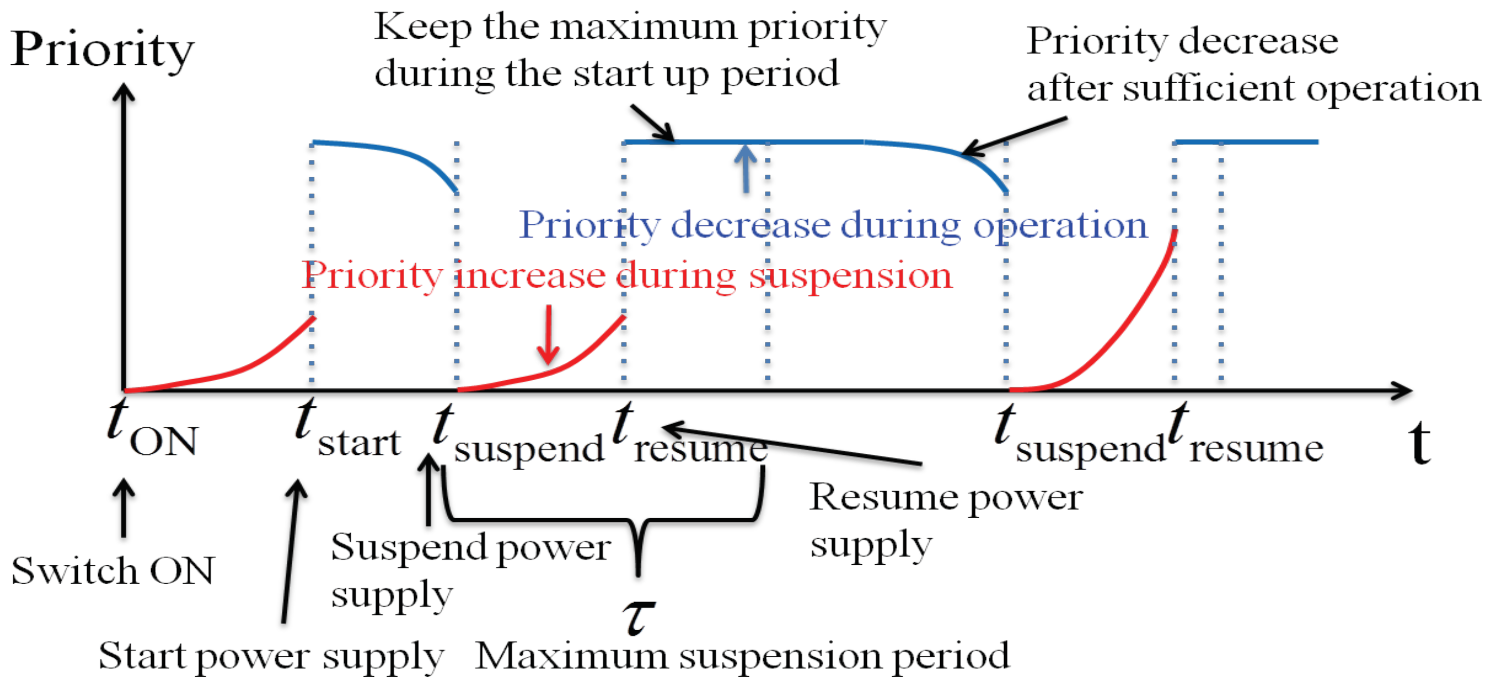
Figure 3.
Storage-supported Energy on Demand system overview with multiple power generators.

Figure 4.
Time shifting of power consumption from blue box to pink box by energy storage system to minimize user’s dissatisfaction.
Figure 4.
Time shifting of power consumption from blue box to pink box by energy storage system to minimize user’s dissatisfaction.
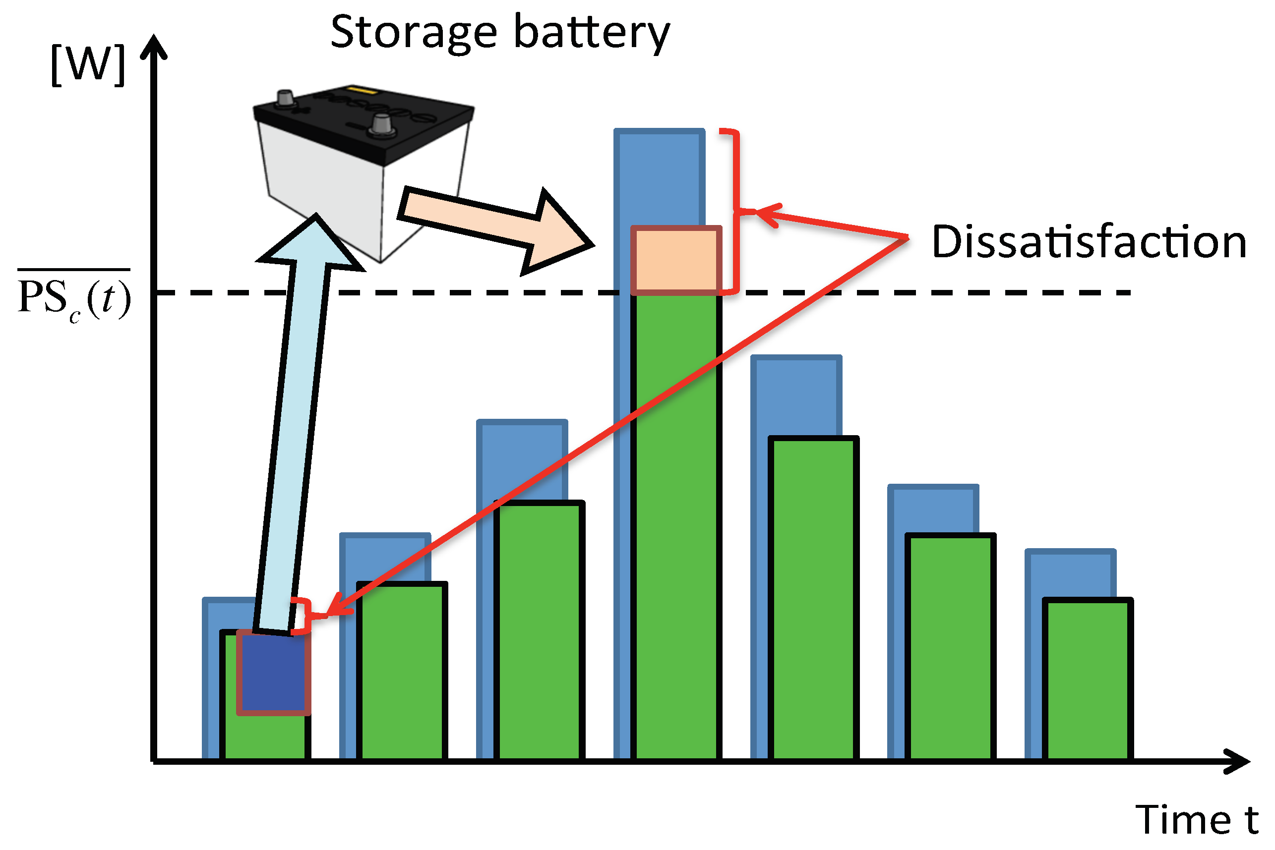
Figure 5.
Load factor of utility power source.
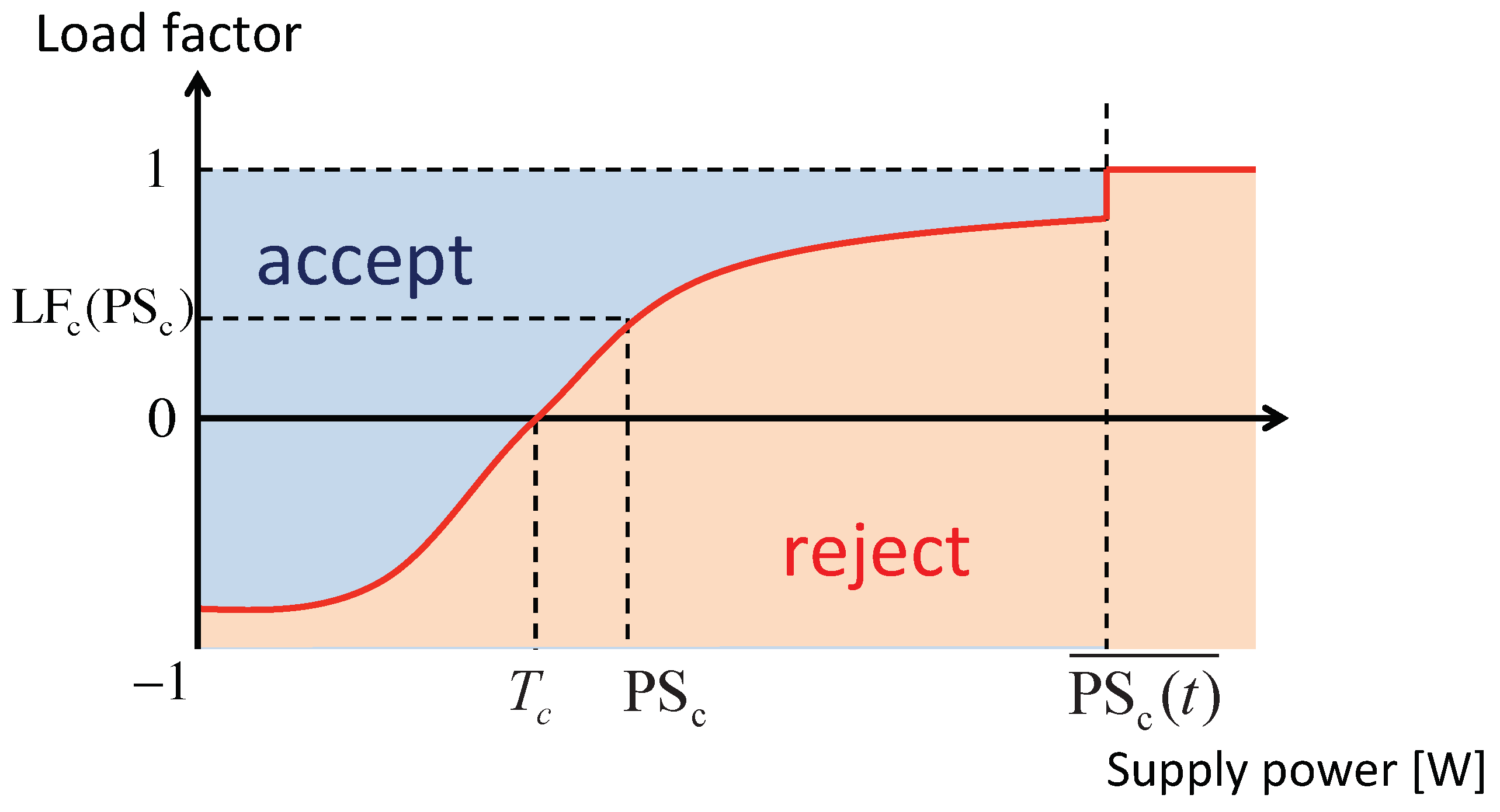
Figure 6.
Load factor of storage battery.
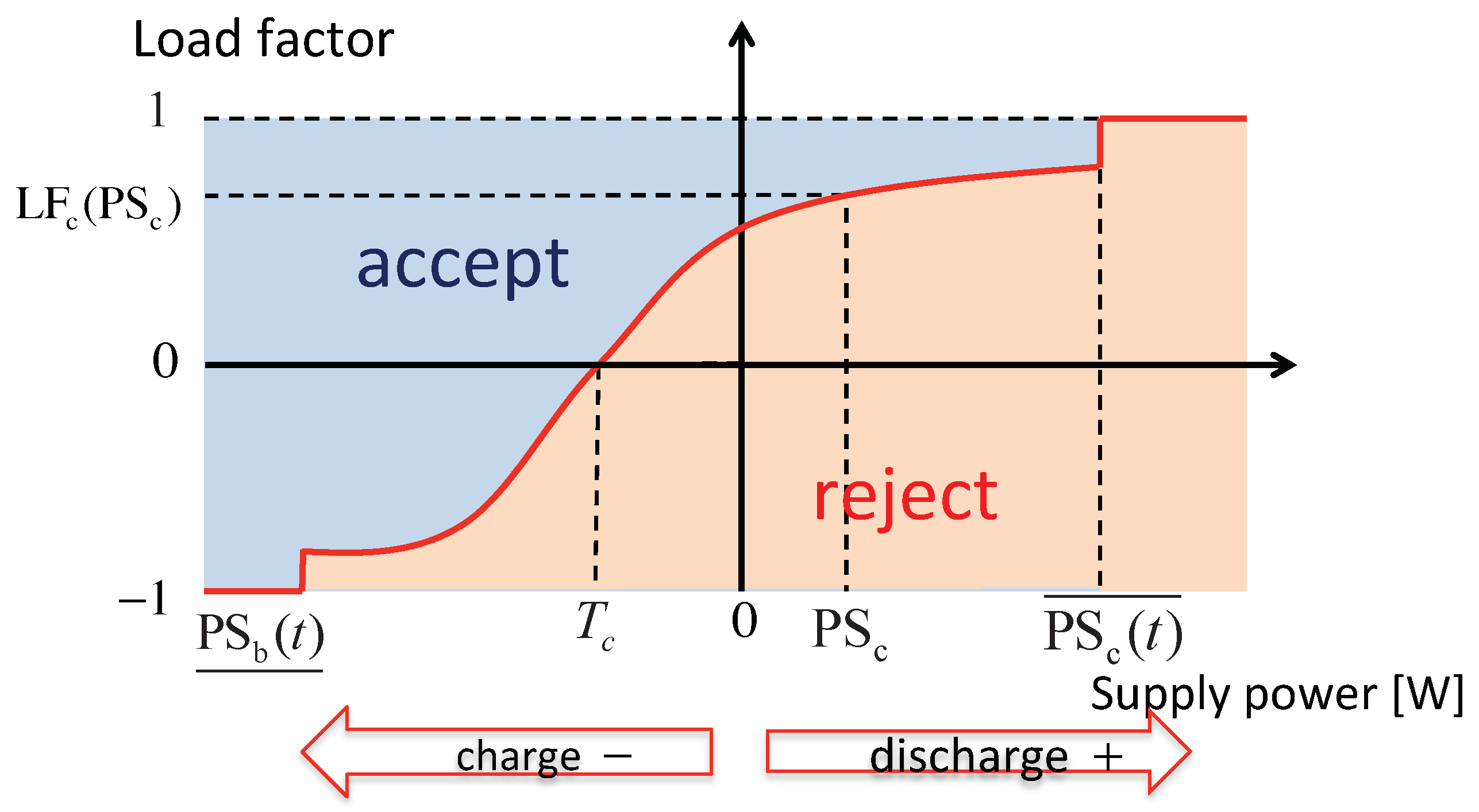
Figure 7.
Real-time mediation.

Figure 8.
Algorithm for appliance-source mediation.
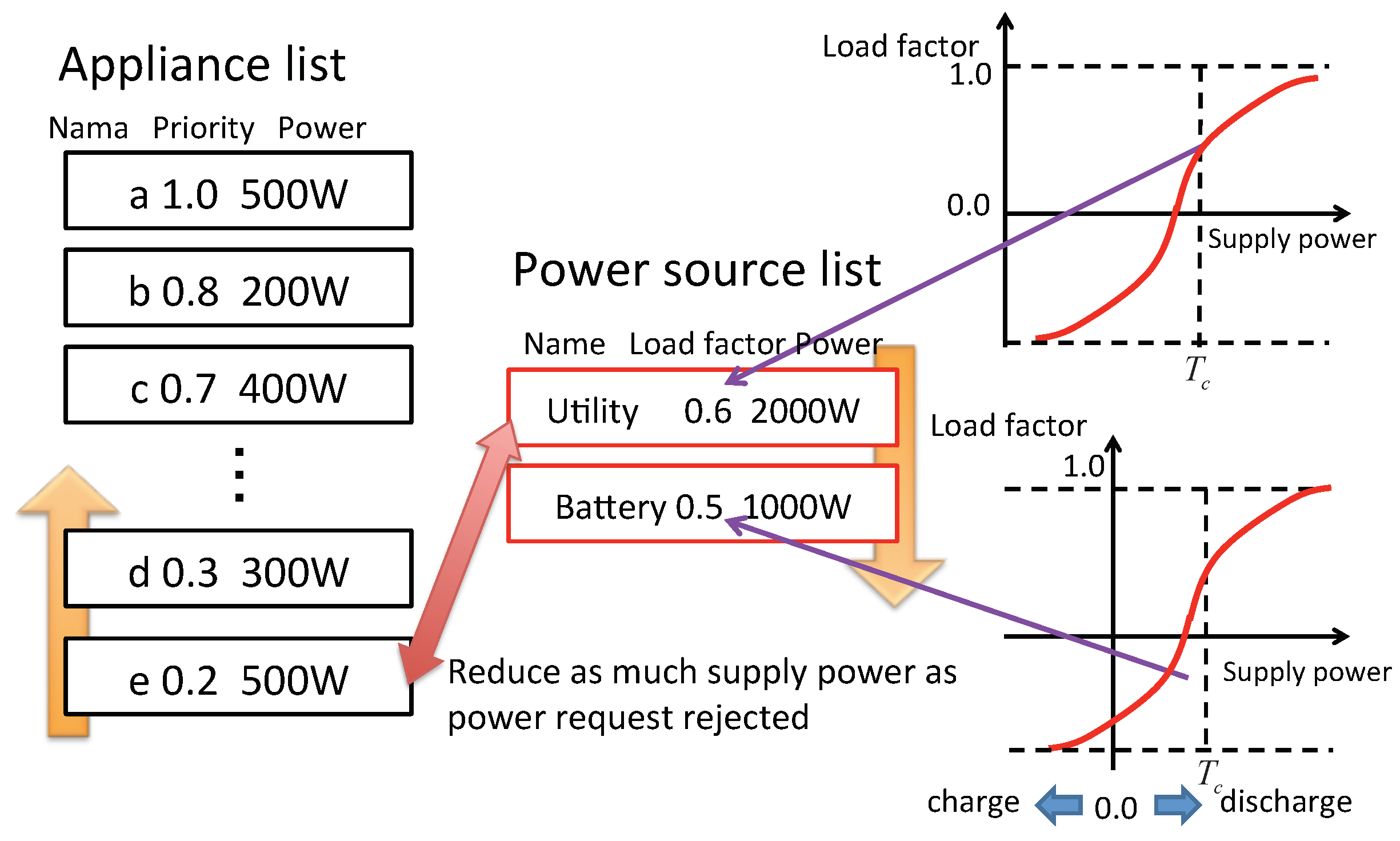
Figure 9.
Smart apartment room.
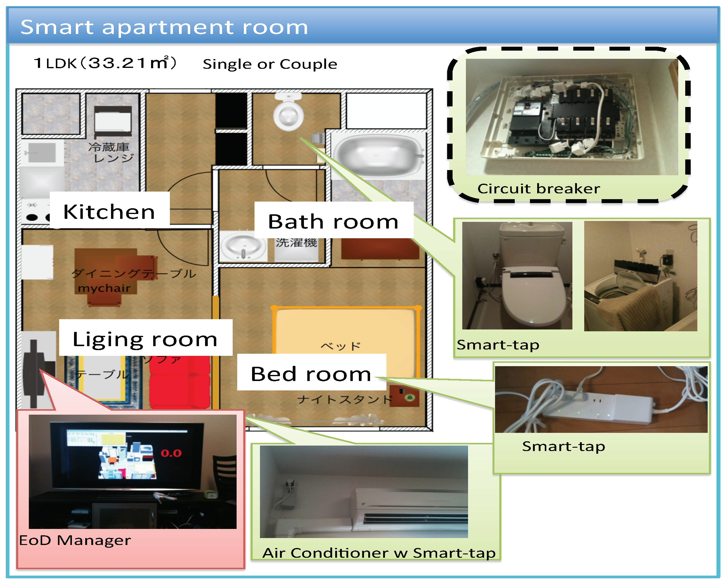
Figure 10.
Results for the off-line planning.
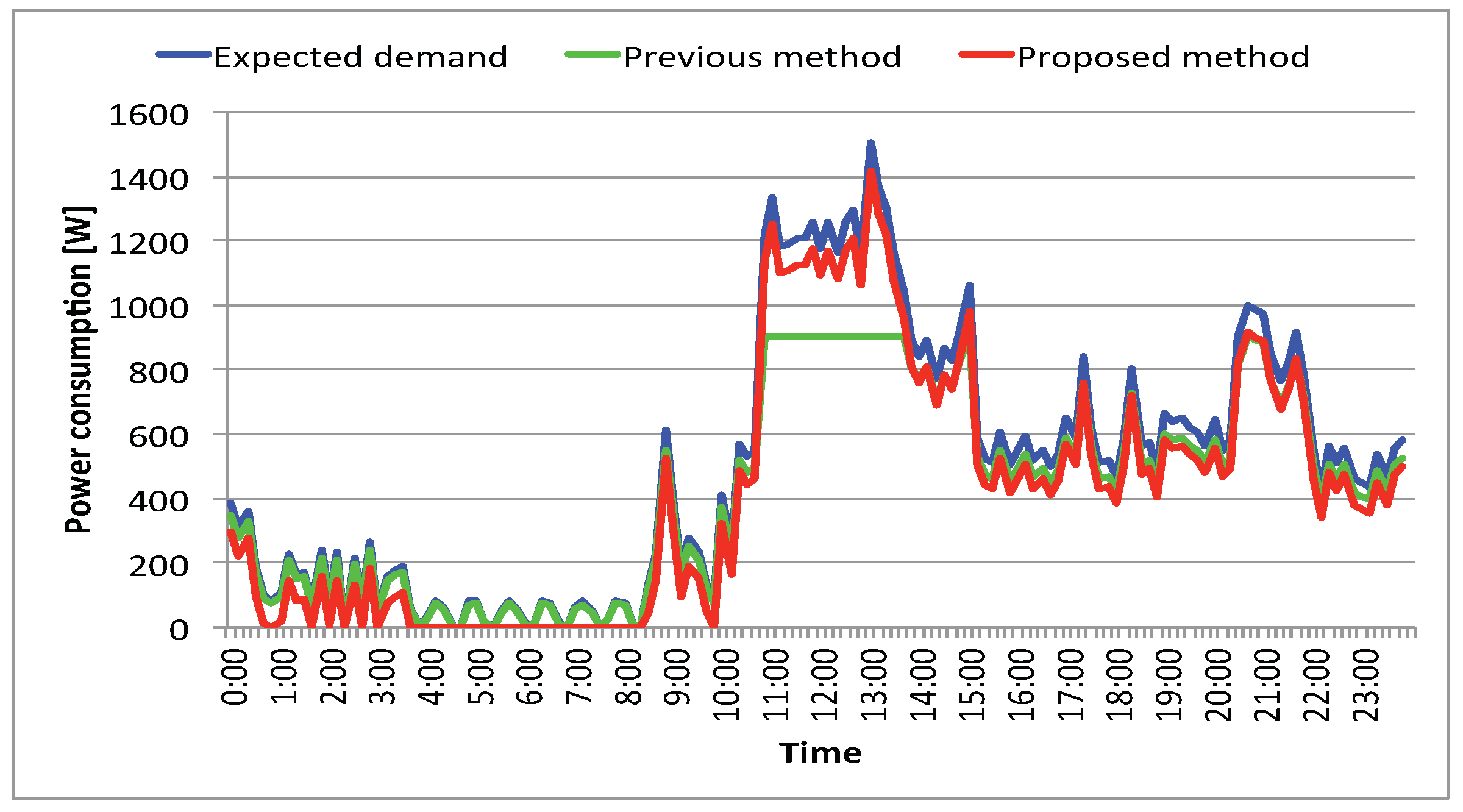
Figure 11.
Charge–discharge plan for a storage battery.
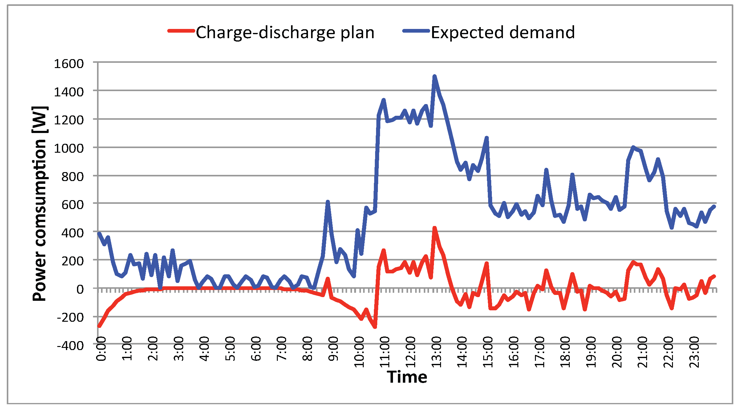
Figure 12.
Charged energy for a storage battery.
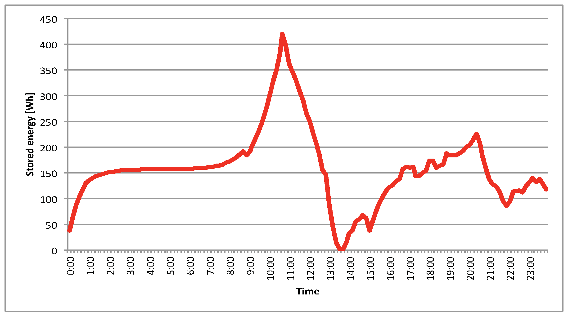
Figure 13.
Result of conventional EoD system.
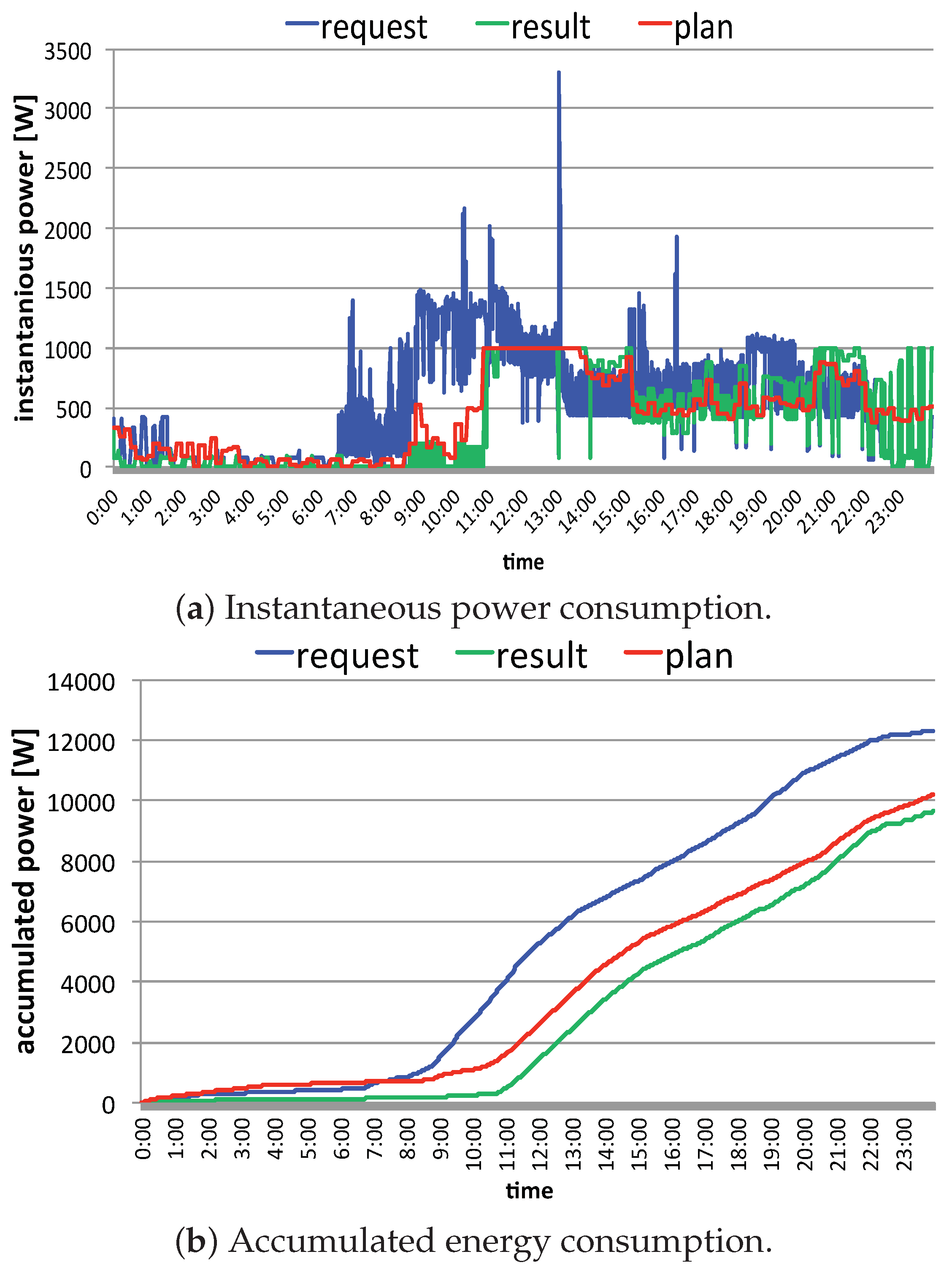
Figure 14.
Result of proposed real-time mediation method.
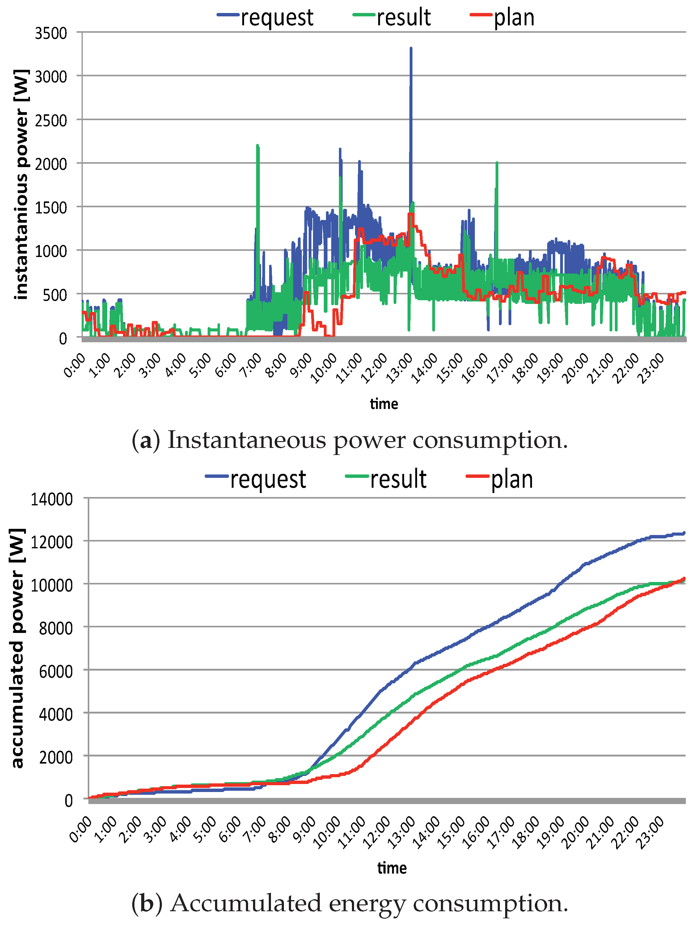
Figure 15.
Dissatisfaction and flattening rate.
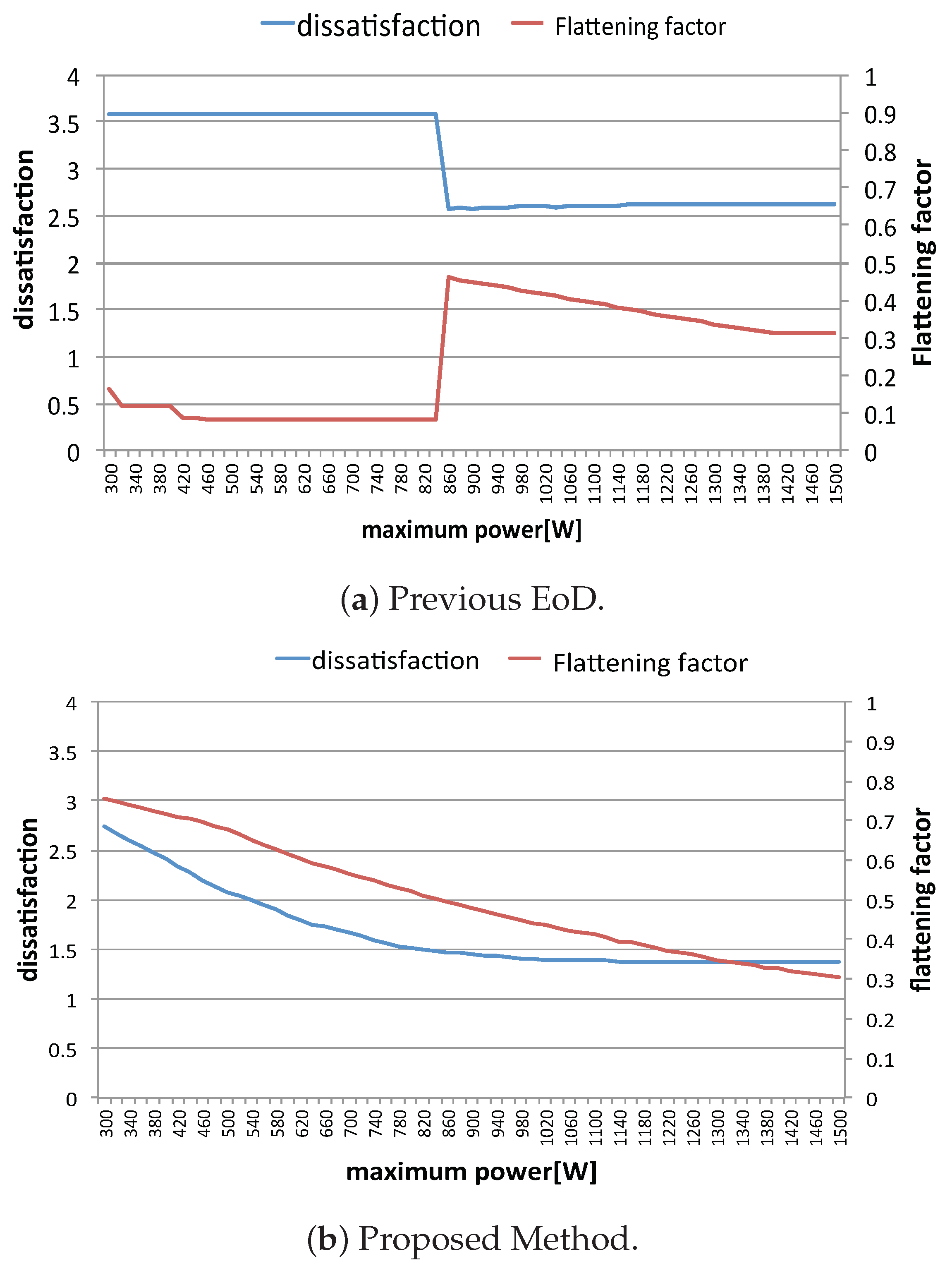
Figure 16.
Power consumptions for previous EoD system against changing maximum power limit.
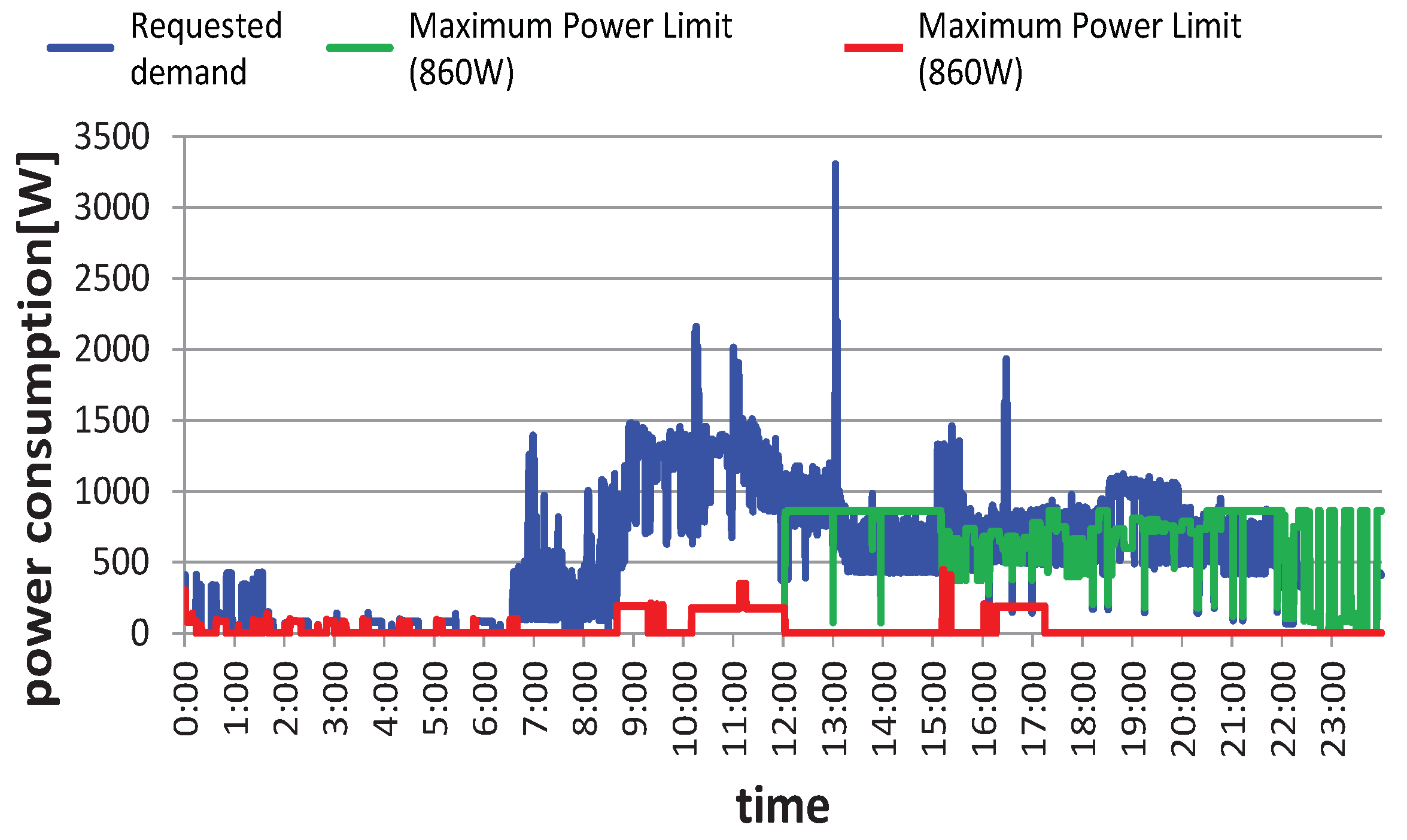
Figure 17.
Results of peak-cut by using storage battery.


Table 1.
List of appliances and their properties.
| Controllability | Appliances |
|---|---|
| Adjustable Time-shiftable Interruptible | pot |
| Adjustable Interruptible | air-conditioner, heater |
| Adjustable | lighting (living room, bedroom, kitchen, entrance, restroom, bathroom), TV (adjust brightness), electric carpet |
| Time-shiftable Interruptible | coffee maker |
| Interruptible | refrigerator |
| Time-shiftable | rice cooker, washing machine |
| Non-controllability (priority is fixed to 1.0) | DVD player, microwave oven, washlet, IH cooking heater |
Publisher’s Note: MDPI stays neutral with regard to jurisdictional claims in published maps and institutional affiliations. |
© 2022 by the authors. Licensee MDPI, Basel, Switzerland. This article is an open access article distributed under the terms and conditions of the Creative Commons Attribution (CC BY) license (https://creativecommons.org/licenses/by/4.0/).
Share and Cite
MDPI and ACS Style
Javaid, S.; Kato, T. Adaptive Control of Energy Storage Systems for Real-Time Power Mediation Based on Energy on Demand System. Designs 2022, 6, 97. https://doi.org/10.3390/designs6050097
AMA Style
Javaid S, Kato T. Adaptive Control of Energy Storage Systems for Real-Time Power Mediation Based on Energy on Demand System. Designs. 2022; 6(5):97. https://doi.org/10.3390/designs6050097
Chicago/Turabian StyleJavaid, Saher, and Takekazu Kato. 2022. "Adaptive Control of Energy Storage Systems for Real-Time Power Mediation Based on Energy on Demand System" Designs 6, no. 5: 97. https://doi.org/10.3390/designs6050097