

Phase Change Materials—Applications and Systems Designs: A Literature Review


Engineering Faculty, University Constantin Brancusi of Targu Jiu, Republicii 1, 210152 Targu Jiu, Romania
*
Author to whom correspondence should be addressed.
Designs 2022, 6(6), 117; https://doi.org/10.3390/designs6060117
Submission received: 20 October 2022
/
Revised: 6 November 2022
/
Accepted: 15 November 2022
/
Published: 18 November 2022
(This article belongs to the Section Mechanical Engineering Design)
Abstract
:The development of Phase Change Materials (PCMs) applications and products is closely related to the market penetration of the renewable energy technologies. With the initial aim of matching the phase shift between resource availability and demand in solar energy systems, the range of PCM applications expanded rapidly during the last decades, entering economic sectors where some form of passive thermal regulation was required. This review focuses on examining both conventional applications and recent advances and niche areas—such as space applications—where PCM-based systems demonstrated a potential to improve the operation at process level. The literature survey conducted here gave special attention to recent application of PCM-based systems such as data centres cooling and electric vehicles battery thermal management. Recent advances in PCM-based systems designs were surveyed in the second part of the article. The main PCM containment and system integration directions were discussed and recent representative studies were discussed. Some topics considered marginal but nevertheless essential to large scale implementation of PCM-based systems were mentioned and their coverage in the literature was assessed: health risks, environmental and lifecycle issues.
1. Introduction
The development of renewable energy sources, a process which started during the 80s, received incentives from many sides. It is not entirely correct to say that the perspective of conventional fuel exhaustion caused exclusively the massive investment in renewable energy technology development; other technological developments such as solar cells based on polycrystalline technology reaching efficiency values in the range of 47% (a value considered impossible to reach a decade ago) as reported by Geisz [1], or fiber glass reinforced polyester or epoxy for wind turbine blades—Mishnaevsky [2], and generally speaking, the progress in the large area of physics and material science, led to a quantitative and qualitative development of all renewable energy technologies. Unlike conventional energy technology such as fossil fuel, most renewable energy technology has unpredictable availability and variable output. This turns out to be a major issue both in cases of integration into centralized grids and especially in cases of micro grids and distributed generation. In this last case, Energy Systems Integration becomes more complicated in terms of coordinating the operation and planning of sub-systems under reliability and cost-effectiveness principles.
Energy storage technologies have the key role of matching the demand with the supply, thus contributing to peak shaving and downsizing the rated capacity of the generation equipment. The energy storage concept is not new and it has many components. In order to reduce conversion losses (due to inherent irreversibility in the conversion chain) and capital cost with conversion equipment it is preferred to store energy in the form that is required for consumption. Thermal energy storage is just one of the many existing energy storage technologies.
In case of thermal energy storage systems, thermal energy is delivered to a storage system where it is stored for different periods of time and, when the consumer requires it, the stored energy is delivered in the same form (thermal energy). The absence of a conversion process into another form of energy makes the thermal energy storage process highly efficient, with losses incurred by the heat transfer from the storage system to the environment. Thermal storage can be achieved in three main ways:
Sensible heat storage. It consists of storing heat in a liquid or solid medium by means of varying its temperature. The choice of the storage medium depends on the process temperature and the desired capacity. Water is a good choice since it has high specific heat capacity and its vaporization temperature can be increased by increasing the pressure. Variation of the temperature in the case of sensible heat storage results in exergy loss, directly proportional to the temperature variation.
Latent heat storage. During the charging phase, the thermal energy is delivered to a medium that undergoes phase change from solid to liquid. The thermal energy is stored in this case mainly as latent heat with very small variation of the temperature. The exergy loss is minimized in this case and the storage capacity is significantly higher than in the case of sensible storage.
Chemical storage. Chemical thermal energy storage is achieved by means of reversible endotherm/exotherm chemical reactions using a thermochemical material such as silica gel/water, magnesium sulphate/water, lithium bromide/water, lithium chloride/water, and NaOH/water, Kalaiselvam and Parameshwaran [3].
This review paper will focus on latent heat storage with (PCMs). PCMs-based technologies extended considerably their typology and range of applicability as well. The main challenges and research directions when it comes to PCMs applications are selection of the appropriate PCM for the given system, design considerations in order to enable system integration, environmental, economic and lifecycle issues, and general engineering issues. Given the large range of applications of PCMs, the design paradigms vary considerably and must be adapted to the specific application. This paper will present a general review of design directions appropriate for different PCMs and application with a focus on system integration.
This review explores and attempts to bring updated information in two directions:
- -
- PCMs applications with a focus on areas where PCMs entered recently as well as on areas where PCMs utilization has been long established but the literature reports are scarce. Among most recent PCMs applications reported in the literature the most important can be mentioned: temperature control in DCs, fresh e-commerce, thermal management of electric vehicles battery systems and thermal comfort in the vehicle cabins. Other important PCMs applications that have been long implemented but not extensively presented in the literature are aerospace applications. This review attempts to synthesize main applications in the aerospace sector;
- -
- PCM systems design: challenges to overcome, design strategies and solutions.
Another novelty element of the present review is a discussion on the impregnation mechanisms and common impregnation methods in manufacturing form-stable PCMs.
2. Phase Change Materials applications
The main consideration that has to be accounted for when it comes to the design of a PCM system are the nature of the PCM and the application.
Classification of PCMs is presented in Figure 1. Eutectics are a special class of PCMs consisting of a combination of both organic and inorganic compounds which dissolves at a specific atomic ratio that then freezes and melts in turn, producing a crystal mixture by crystallization. Eutectics have more desirable properties as a result, which include better latent energy and an extremely high melting temperature, Lawag and Ali [4].
Generally, inorganic PCMs are relatively inexpensive, widely available, chemically stable and less flammable than organic ones. Another important consideration is the thermal conductivity coefficient, which tends to be higher in the case of inorganic PCMs. Inorganic PCMs have though some disadvantages compared to organic PCMs [5]: tendency to undergo supercooling before crystallization, are corrosive to most metals, require nucleating and thickening agents, suffer from phase segregation. There are also process requirements that render the usage of PCMs meaningful or not. The most important is the temporal variation of the load; PCMs can only make a difference in the case of fluctuating/periodic loads.
Any PCM application requires containing in some form the PCM, in order to keep it in a volume especially when transition to liquid phase occurs. Containerization is achieved in many forms depending on the PCM nature, application, temperature variation range and system integration.
Commonly used PCMs are paraffins, fatty acids and esters and salt hydrates. Recently, ionic liquids have been considered as PCMs, Matuszeka et al. [6]. In a recent review article Lawag and Ali [4] found that 81% of the research articles that were included in the review studied organic PCMs, 15% inorganics and 4% others. As organic PCM, paraffin was the research topic in 79% of the articles considered in [4].
2.1. Solar Energy Storage
Latent heat storage is an effective way to address the intrinsic intermittence and daily unpredictable fluctuations. The usual temperature range for solar energy storage is 300–400 °C, Dinter et al. [7]. For such application, the appropriate PCMs are usually inorganic, Michels and Pitz-Paal [8], Pielichowska andPielichowski [9]. Dinter et al. [7] described a cascaded PCM storage system with five stages, each stage using a different PCM, arranged in such way that the PCM with the highest melting point is placed on the first position during the charge phase and on the last position during the discharge phase. The inorganic PCMs described in [7] are with melting point 380 °C, with melting point 360 °C, with melting point 335 °C, with melting point 320 °C and with melting point 306 °C. The serial arrangement of the PCMs offers two major advantages: (1) reduces the exergy loss by minimizing the temperature difference between the PCM and the charging/discharging fluid and (2) increases the storage capacity benefitting from latent storage instead of sensible storage. A comprehensive review of solar cooling methods and thermal storage systems and a more detailed discussion on cascaded storage for solar thermal applications can be found in Chidambaram et al. [10].
2.2. Space Applications
The space thermal environment is characterized by temperatures as low as 2.725 K solar radiation intensity 1353 W/m2 and heat transfer between the spacecraft and environment almost exclusively by radiation, He et al. [11].
Space applications, subject to periodic, high amplitude thermal cycles, can benefit significantly from implementation of PCM-based temperature control systems. The type of PCM systems differ significantly depending on the mission type. Obviously, in case of deep space and planetary explorations spacecrafts, the thermal environments vary in a much higher extent than orbital spacecraft. For such vehicles, it is considerably more important to ensure heat rejection during the hot operating phases and maintain the temperature range required for safe systems operation during cold environments. Special problems are encountered in case of geostationary orbits. Unlike in the case of low Earth orbit vehicles, the influence of the Earth is almost negligible, except in the case of shadowing during eclipses. However, seasonal variations in the direction and intensity of the solar input impact considerably the design of the thermal control systems. In particular, a major issue in this case is the heat rejection system, which has to dissipate the heat to the deep space (spacecraft area not exposed to radiation). Ymer and Adami [12] developed a two-dimensional analytical model for the heat transfer process in a PCM heat storage system for space applications. The effect of the main thermal and geometrical parameters was investigated by performing a parametric study. In space applications, any spacecraft subsystem is subject to weight/volume constraints. Among studies attempted to develop PCM-based thermal control systems under such constraints, attempting to maximize storage capacity-to-volume ratio and improve the behaviour under dynamic loads, the following can be mentioned:
- Lafdi et al. [13] carried out a numerical study to predict the thermal performance of graphite foams infiltrated with PCMs for terrestrial and space applications. For space applications, the average value of the output power of the new energy storage system has been increased by more than eight times. In the case of terrestrial applications, the average output power using carbon foam of porosity 97% was about five times greater than that for using pure PCM. Other studies discussed the appropriateness of various PCMs for the particular conditions of the space environment.
- Cui et al. [14] studied numerically and experimentally the eutectic mixture. It was found that the output temperature of the working fluid tubes met the expected demand during the sunlight and eclipse period and the maximum temperature.
- He et al. [15] developed a two-dimensional model for PV-PCM-TE coupling system to investigate the energy transfer and conversion performance under space conditions. A suitable PCM was selected and it was integrated into the system both in pure form as well as a MFCPCM. A combined performance criterion was defined considering the power generation efficiency and the system mass, which is a critical evaluation index for space systems. The system design is presented in Figure 2b (PCM only) and Figure 2c (MFCPCM). The average total efficiencies for PV-TE, PV-PCM-TE and PV-MFCPCM-TE were 29.50%, 30.50% and 30.61%, and the corresponding average power density were 30.34 W/kg, 22.39 W/kg and 21.20 W/kg, respectively. The authors designed an orthogonal experiment in order to assess the effect of the PV-MFCPCM-TE on the power generation efficiency and power density. After running all cases of the orthogonal experiment, it was found that the mass of the ceramic layer and PCM layer had the highest weight of the PV-PCM-TE system total mass. It was concluded that reducing ceramic layer mass and using high melting enthalpy PCM was an efficient way to further reduce the mass of PV-PCM-TE coupling system and promote its application in space system.
He et al. [11] developed a numerical model for space PV-PCM-TE systems using paraffin as PCM aluminium foam as additive for heat transfer enhancement. The PV-PCM-TE system was considered to be attached to spacecraft orbiting the Earth every 90 min, with 60 min on the Sun side. A two-dimensional numerical model was developed for the PV-MFCPCM-TE system to investigate its periodic performance under space conditions.
The operation of the system has two stages: During the illumination period Figure 3—left, the incident solar energy is absorbed by PV cell, part of the absorbed energy is converted to electrical power, and the rest is converted to thermal energy. Then, part of the thermal energy is dissipated to space by radiation through the upper surface of PV cell, the other part is transferred to MFCPCM module. In MFCPCM module, part of the thermal energy is stored in PCM through the solid–liquid phase change process and the other is transferred to TE module. In TE module, some of the thermal energy is converted to electrical power and the other is transferred to heat sink module and be dissipated to space by radiation. During the shadow period Figure 3—right, there is no incident solar energy and the PV cell stops working, while the thermal energy stored in PCM during illumination period is released through the liquid-solid phase change process and PCM is regenerated. Some of the released thermal energy is transferred to PV cell and be dissipated to space by radiation, the other part is transferred to TE module. Then, in TE module, part of the thermal energy is converted to electrical power and the other is transferred to heat sink and be dissipated to space by radiation.
Firstly, the PV-MFCPCM-TE systems with different heat dissipation conditions were investigated, the problems of energy imbalance and MFCPCM failure and their effects on overall performance of PV-MFCPCM-TE system were discussed. Then, the global structural parameters optimization was carried out, and the optimal parameter combination was derived considering both the periodic energy balance and system power density.
2.3. Temperature Control of Electronics
PCM-based thermal control systems are very effective for device with intermittent operation. Most of the electronic chips available on the market today operate safely at maximum temperature values ranging from 85 °C to 120 °C. Applications of PCMs in thermal control of electronic devices ranges from PCM-enhanced heat sinks: a hybrid heat sink which combined an active plate fin heat sink with its tip immersed in a passive PCM, Krishnan et al. [16]; Composite heat sinks using a vertical array of fins made of PCM and highly conductive base material were constructed by Akhilesh et al. [17]; inclusion of PCM in the cavities of the heat sinks with the purpose of improving the cooling performance at high input power; heat pipe modules with n-tricosane (melting point 380 °C) as PCM, which resulted in a lower cooling fan power consumption (by 46%) and a lower device temperature (by 12.3 °C).
Photovoltaic panels thermoregulation is required to maintain the efficiency at the design value. PCMs find a good application in systems designed to maintain the temperature of the photovoltaic panels. Quasim et al. [18] assessed the effect of fins inserted into PCM, by varying the number of fins as 2, 5, 8 and 11 improved heat conduction within PCM through metal contact, PV cell temperature lowered by maximum 22.9 °C, 23.7 °C, 24.1 °C, 24.9 °C and 26.5 °C with finless, 2-fin, 5-fin, 8-fin and 11-fin PV/PCM configurations, respectively, improving electrical conversion efficiency from 10.2% to 10.9%, 11.3%, 11.6%, 11.8% and 12.2%, respectively.
2.4. Biomedical Applications
Biomedical applications requiring some sort of thermal protection can integrate PCMs. In this area, the PCM application range is wide, from thermal control during transport/storage of biologic tissue to thermal control/protection for in situ interventions. Such applications are useful for example in cases where skin temperature must be kept within a range, e.g., heat/cool therapy, Zhang [19]. More extensively, PCMs are used for thermal control during transport of storage of biological products, Mondieig [20]. De Santis [21] conducted a study attempting to absorb quasi-isothermally the heat generated during in situ polymerization of PMMA for bone cement composites in order to reduce the peak temperature. Another similar study was presented by Pielichkowska and Błaźewicz [22]. An interesting type of PCM application in medicine was a PCM-based thermal control system to protect the healthy tissue around a malignant tumour during cryo-surgery, Lv et al. [23].
2.5. Thermal Storage in Building Applications
It is known that the built environment contributes with a significant share to the overall energy consumption.
As the regulations regarding the energy efficiency become tighter, the building industry had to adapt and come up with solutions to comply with the ultimate goal of reducing the energy consumption for HVAC, lighting, building services, etc. A large share from the built environment energy consumption is occupied by HVAC. The periodically fluctuant HVAC load suggest that using some forms of PCM-based thermoregulation systems can result in an improvement in the built environment energy efficiency. Due to the high potential of PCM-based systems of improving the energy efficiency in the built environment, a large range of applications, both passive and active, have been developed.
2.5.1. Passive Storage Systems
The term passive implies that the systems require little or no energy at all during the operational charge/discharge phases of the functional cycle. Table 1 presents several representative experimental and numerical studies on passive thermal regulation systems for the built environment integrating PCMs in various forms.
2.5.2. Active Storage Systems
2.6. Increasing the Storage Capacity of Hot/Cold Water Tanks
In order to reduce the tank volume for the same storage capacity, PCM modules can be integrated in water storage tanks. In order to optimize the tank-PCM elements system it is necessary to understand the dynamic behaviour and the heat transfer characteristics of such systems. Wan et al. [43] developed a dynamic model for tube-capsulated PCM storage tanks using a thermally VRC network in a quasi-two-dimension. The accuracy of the quasi-2D VRC model was investigated using data available in the literature, and the mean absolute error was within 1.0 °C. Jahangir and Labbafi [44] investigated experimentally a GSHP system with a PCM energy storage tank to improve the performance of the Dunaliella salina microalgae open culture system. Factors including the amount of PCM in the energy storage tank, the flow rate of the circulation fluid and the amount and use of nanoparticles in the fluid affect the temperature of the pool water in the coldest and hottest day of the year, the growth rate of microalgae and the performance of the system. the use of this system in cooling mode has a 48.7% higher coefficient of performance and a 54% increase in weekly microalgae production compared to a single GSHP system. Likewise in heating mode, it causes a 53.7% increase in the coefficient of performance and a 27.6% increase in microalgae production rate. A major issue that has to be resolved during the design phase in case of storage tanks is thermal stratification. Thermal stratification does not affect necessarily the storage capacity but it has a negative effect on the dynamic of the charging/discharging process. On the other hand, proper design can take advantage of the natural thermal stratification and improve the efficiency of the charging/discharging process, as shown in [44]. Liang et al. [45] performed an experimental and numerical study to demonstrate a novel stratified storage tank of PCM-in-water nano-emulsion for cold storage in building radiant cooling applications. A 20 wt% PCM-in-water nano-emulsion was utilized as both the storage medium and heat transfer fluid. The experimental results showed that the cooling capacity of a cooling panel was increased by 60% with phase change emulsion circulating in the loop. The effective energy storage capacity of the stratified storage tank was 1.6–1.7 times than that of water in a wide range of discharging flow rates/speeds. In comparison with other PCM thermal energy storage designs, the stratified storage tank of PCM-in-water nano-emulsion has the advantage of a lower temperature difference between the cooling source and the demand, and thus raising the overall system energy efficiency. Wu et al. [46] investigated a solar DHW storage tank using sodium acetate trihydrate as PCM. The thermal stratification of latent heat storage water tanks within different locations of PCM units and inlet flows was investigated experimentally and numerically. The results show that in the charging process, as the inlet flow increases, the thickness of the thermocline gradually increases, with the resulting in worsening of the mixing process. These findings are useful in optimal design of domestic hot water storage systems.
2.7. Two-Phase LHFTF
LHFTFs consist of a liquid medium in which PCM particles are dispersed. The apparent specific heat of the functional fluid will be considerably higher than that of the pure fluid since the PCM particles absorb/release heat almost isothermally. The PCM particles can enhance the heat transfer rate between the fluid and the tube wall, reduce the mass flow rate and pumping power, Pielichowska and Pielichowski [9] (this happens up to a concentration, where the density of the fluid increases, which results in an increase of the pumping power). A major issue in designing and developing functional thermal fluids is maintaining the PCM chemical stability and physical integrity. The following types of LHFTFs demonstrated compliance regarding the previously mentioned conditions Pielichowska and Pielichowski [9]:
- Phase Change Slurries; the PCM is microencapsulation by means of chemical processes by creating a shell that contains the PCM. The microcapsules must not form agglomerations, deposits or fouling so the PCS maintains its homogeneity and can be pumped through tubes and ducts.
- Emulsion of fusible components, with the PCM dispersed in a carrier fluid and kept in suspension by a surfactant agent
- Ice slurries
LHFTS applications have been reported as follows: Diaconu et al. [47,48] investigated the heat storage properties and heat transfer particularities of a microencapsulated slurry containing paraffin-based PCM (Rubitherm RT6) with a high concentration of 45% w/w for cold storage in air conditioning applications. Due to the difficulties in deriving a heat transfer correlation for the PCS, the authors proposed a new method of evaluating the heat transfer coefficient for the PCS, by comparing it with that of water, for the same conditions. It was found that the heat transfer coefficient for the PCS was higher than that of water.
As the PCSs offer most advantages over other types of LHFTS extensive research has been carried out on production of stable PCM microcapsules dispersions and development of microencapsulation techniques. Ikutegbe et al. [49] presented a technique to encapsulate low melting PCM photo-induced suspension polymerization technique using an ultraviolet perfluoro-alkoxy (UV PFA) coiled tube reactor. Commercially available Pure Temp (PT) 6 (melting point 6.2 °C and latent heat of fusion 150.1 kJ/kg) and cross-linked polymethyl methacrylate were used as PCM and shell material, respectively. The effect of different synthesis parameters such as polymerization time and optimum core–shell mass ratio were thoroughly investigated. The morphology, chemical stability, thermal properties, and microcapsules produced at the optimal yield were examined and surface morphology analysis showed the absence of distortions and complete PCM core entrapment. The MEPCM had a peak melting temperature of 8.2 °C and an average latent heat of 131.1 kJ/kg, representing 87.4% PCM content. Guo et al. [50] designed and prepared via single-step in situ polymerization. OSS-MEPCMs with n-octadecane as core material and silicone as shell material. The effects of core/shell ratio on morphology, thermal properties, thermal stability and mechanical properties of OSS-MPCMs were further investigated. The authors reported an encapsulation efficiency of roughly 86%. Chen et al. [51] prepared a new type of MEPCM with n-docosane CH3-(CH2)20-CH3 as the PCM core and titanium dioxide as shell material. The authors reported a melting point of approximately 40 °C. In order to optimize the formula of the microcapsules, single-factor analysis on the emulsifier type, its mass fraction, ultrasonic frequency, pH, and core–shell ratio were performed. The results showed that the MPCMs prepared in this paper had a particle size of 2–5 μm and spherical shape. Its surface was uniform and smooth and the titanium oxide was well dispersed around the n-docosane, completely coating the n-docosane without impurities. The MPCMs had good performance in terms of thermal properties and heat storage when using 0.40% sodium dodecyl sulphate as an emulsifier, 10 min ultrasonic, a 3.5 pH value, and a 1:1 core–shell ratio. However, the stirring method, time, and experimental reaction temperature also influenced the properties of the material, which was not studied in the experiment reported by the authors. A state-of-the-art review presenting recent advances in PCM microencapsulation was carried out by Al-Shannaq et al. [52].
2.8. Textiles with Thermoregulation Features
So called smart textiles—fibres incorporating PCM microcapsules to improve the thermal comfort offered by functional garments such as space suits in environments subject to large temperature variations. In fact, smart textiles were among the first PCM applications. A review of PCMs for smart textiles was carried out by Mondal [53]. Lu et al. [54] developed a material structure with high-performance in overcoming leakage of paraffin wax by the coaxial electrospinning technique using core-sheath structured smart textiles with paraffin wax as core layer and polyacrylonitrile as sheath layer. In order to improve the heat absorption from solar radiation, the hexagonal cesium tungsten bronze (Cs0.32WO3) with high near-infrared region emission factor was incorporated in the textiles. The authors reported an encapsulation efficiency of 54.3% (latent heat of 60.31 J/g) and no significant change of latent heat for the smart textiles after 500 heating-cooling cycles was found.
2.9. Automotive Applications
In the automotive industry, PCMs can have several applications, such as Pielichowska and Pielichowski [9]: pre-heating catalytic converters; engine cooling/pre-heating; thermal comfort in the cabin; fuel/air preheating. The objectives of using PCM-based thermal energy storage systems in automotive applications were mainly to downsize the cooling system and to reduce the engine warm-up time.
2.9.1. Pre-Heating Catalytic Convertors
Catalyst performance during cold start and warm up differs with fuel, which influences the cylinder combustion and exhaust temperature. The exhaust temperature for spark ignition engines is much higher than that of compression ignition engines, which causes shorter Three-Way Catalyst light-off time in cold start conditions. Significant research effort has been made in this direction, as presented in a comprehensive review study, Gao et al. [55], as the exhaust temperature has a critical role in the catalyst performance. Ugurlu and Gokcol [56] reviewed energy storage systems based on PCMs for internal combustion engines and catalyst preheating, including analysis of the suitable storage materials and the structure of the devices. The effectiveness of fuel, oil and catalyst preheating by using residual heat stored in PCMs depends however on the frequency of start/shut down operations. It results that this technology is not practical for any type of vehicle, being only suitable for vehicles running regularly for long time at low speed, such as urban buses or airport shuttle buses [56].
Korin et al. [57] designed a system consisting of a catalytic converter for an internal combustion engine embedded in a PCM with the melting point approximately 353 °C (a few degrees above the light-off temperature of the metallic catalyst). The objective of this system was to reduce the transient heating up period of the catalyst (the time interval required for the catalyst to reach the design operating temperature). However, the effectiveness of such system depends considerably on the start/shut down frequency, which must be high enough in order not to allow the PCM to solidify and cool down.
2.9.2. Engine Cooling/Pre-Heating
Given the fact that engines waste approximately 50% of the heat resulting from fuel combustion as residual heat (exhaust gas, coolant and lubricant oil) the idea of recovering this heat and storing it is meaningful. Kim et al. [58] designed an engine PCM-based cooling component with the purpose of reducing the volume of the conventional cooling system. Three prototypes were designed: full-size, down-sized, and a down-sized prototype with a heat accumulator containing the PCM inside. It was found that the full-size of the cooling system component was down-sized by 30%; the smaller design failed to dissipate the peak heat load and consequently led to a significant increase in the coolant temperature, around 25 °C greater than that in the full-size system. The authors concluded that the peak heat load was reduced in the down-sized system with the PCM-based heat accumulator. Park et al. [59] designed and investigated experimentally a PCM-based prototype heat storage system in order to recover partially the thermal energy released through engine cooling. As a result, a stearic acid was determined to be appropriate based on safety and adequate thermal properties criteria. In order to measure the reduction in engine fuel consumption, a thermal storage system designed for the actual engine was applied to achieve a quick warm-up by releasing stored heat energy directly on the coolant during a cold start. It was found that the system reduced by approximately 18% the warm-up time. Gumus [60] developed an experimental system for thermal energy storage system for pre-heating of internal combustion engines. The PCM used in this study was Na2SO4 · 10H2O. It was found that charging and discharging time of the heat storage system were approximately 500 and 600 s, respectively and temperature of engine increased 17.4 °C with pre-heating.
2.9.3. Fuel/Air Preheating
Soliman et al. [61] proposed a new design of the exhaust waste heat recovery heat exchanger. It consisted of preheating the intake air before supplying it to the compression ignition engine at cold start-up conditions. The heat exchanger was designed of ribbed plates containing paraffin wax PCM. The PCM was used to store the thermal energy released by the engine during the operation for later use in cold start-up conditions. The effect of different design and operating conditions was assessed. The influence of ribs height and spacing, engine rotational speed, and intake air temperature on the thermal energy storage were evaluated. It was concluded that the highest performance was obtained at a rib gap of 90 mm and a rib height of 7.5 mm. Through the warming-up process, in less than 1 min, the cold intake air temperature could be raised from 273 K to 302.2 K. In another study, Soliman et al. [62] conducted a numerical investigation on an air preheating system designed to warm up the engine intake air. The preheating system consisted of a modified plate heat exchanger and an intake air/exhaust gas switching system. Nano-enhanced PCMs were encapsulated in rectangular enclosures of the heat exchanger. Lauric acid and paraffin wax with the melting temperature range 43.5–48.2 °C and 54.2–56.2 °C, respectively were used. Three types of nanoparticles were tested: Al2O3, CuO and SiO2. After testing numerically and experimentally several configurations, it was found that the system was able to increase the intake air temperature with approximately 20 K, improving significantly the engine performance and reducing the emissions during cold start-up.
2.9.4. Thermal Comfort in the Cabin
Krishnamoorthi et al. [63] designed a simple PCM-based system to reduce the heating up of the vehicle cabin due to solar radiation, consisting of a series of copper tubes filled with PCM (paraffin) placed beneath the cabin roof. It was found that the system was able to improve slightly the cabin comfort in a passive and cost-effective way. Afzal et al. [64] designed a passive thermal regulation system for the car cabin by impregnating an organic PCM-coconut oil-underneath the rooftop of the vehicle and empty spaces in door interior. Temperature and relative humidity inside the vehicle cabin with and without PCM were recorded. A significant drop of the maximum cabin temperature was found when using PCM compared to the case without PCM.
2.9.5. Electric Vehicles
The electric vehicles battery is an expensive and sensitive system, which requires some sort of thermal management to operate optimally during charging/discharging cycles. Youssef et al. [65] proposed a novel design optimization to improve the environmental aspect of the cooling system and reduce its weight. The proposed design reduced the complexity and power consumption, also enhanced the bulkiness in the PCM cooling system and pack volume by reducing the amount and weight of the PCM. Luo et al. [66] conducted a recent review on electric vehicles battery thermal management systems based on PCMs. The main conclusions were (1) the next research directions should focus on the improvement of thermal conductivity of PCMs, (2) flame retardancy of organic PCM must be addressed, (3) thermal stability of inorganic PCMs, Phase Change Fluids and flexible PCMs thermal performance must be improved, and (4) the PCM-battery thermal management system coupling must be improved in terms of thermal performance.
2.10. Food Processing/Agriculture
Food industry is one of the more complex and diverse in terms of thermal processes kinetics and temperature level. Food products pre-processing require different types of thermal treatment or thermal regulation during the various phases of the process. Consequently, there are many processes that can benefit from thermal energy storage using PCM-bases systems. Devahastin and Pitaksuriyarat [67] assessed the feasibility of a PCM-based heat storage system applied to a drying system for sweet potatoes using solar energy in order to improve the kinetics of the drying process. The authors found that the drying rate of sweet potato increased with a decrease of the inlet ambient air velocity. The amount of the energy that could be extracted from the LHS was 1920 and 1386 kJ min kg−1 and the energy saving values were 40% and 34% when using an inlet ambient air velocity of 1 and 2 m/s, respectively. A comprehensive review on thermal energy storage systems for solar dryers used in the food industry has been conducted by Bal et al. [68]. A more recent review on solar cookers and dryers conducted by Battocchio et al. [69] mentioned several applications of PCMs in improving the performance of the process for such equipment. Simão et al. [70] investigated a decentralized thermal storage architecture, incorporating PCM into the existing equipment of an agroindustry production line. To assess the feasibility and potential gain in the adoption of this TES/LHS distributed solution, a tempering and mixing equipment for food granules was selected as a case study, representing a larger cluster operating under the operation paradigm of water jacket heating. The behaviour of the equipment, incorporating an inorganic PCM, was investigated numerically using a commercial software. Then, a prototype was built and used in laboratory tests, allowing for data collection and validation of the simulation model. It was concluded that using PCMs, it was possible to partially replace the use of water as a source for thermal storage. Secondly, it was shown that the replacement of 3.5 litres of water by the same volume of S34 PCM resulted in an increase of 1050 kJ (330%) of storage capacity for the same volume, and 102% in the combined set (3.5 litres PCM + 8 litres water). Once the PCM was charged, the gain boosted by the increase in storage capacity was directly reflected in the increase in the period of operation of the equipment in autonomy (without power supply), keeping the chocolate for 1.2 h (32%) more of operation above 30 °C.
The use of PCM in the food industry for low temperature processes has by far more applications than heat storage at high temperatures. Zhang et al. [71] carried out a review on PCMs for cold storage. Several studies were identified in the literature regarding food storage, mentioning PCMs such as Tetrahydrofuran, n-Tetradecane, Formic Acid, Polyethylene glycol 400, Dimethyl adipate, n-Pentadecane. Meng et al. [72] conducted a recent review on applications of PCMs in fresh e-commerce and cold chain logistics. The review study focuses on recent literature describing a new trend and concept, fresh e-commerce, a new branch of the online shopping. The concept is relatively new and it developed exponentially lately, especially with the outbreak of COVID-19. In fact, the number of publications related to latent heat storage for the cold chain and refrigerated transport increased from 10 in 2019 to 35 in 2022, according to a recent literature review conducted by Calati et al. [73].
A novel study presenting the design and performance of a CTES unit consisting of a pillow plate heat exchanger immersed into a low-temperature PCM as the storage medium was presented by Selvens et al. [74]. A technical solution was proposed to couple the evaporation and condensation processes of the refrigeration system with the melting and solidification of a low-temperature PCM in the same heat exchanger. The charging and discharging performance of the plates-in-tank CTES unit was tested using CO2 as the refrigerant and a commercial PCM with phase change temperature of −9.6 °C (RT-9HC). An interesting conclusion of the study was that by design, it was possible to select a discharge characteristic of the CTES unit that matches the refrigeration load curve of the refrigeration plant by changing the plate pitch. A plate pitch of 15 mm was found as the appropriate choice to reduce a peak with a high magnitude and duration of approximately one hour, while 30 mm is most suitable for peaks of about 2 h with a lower magnitude
A recent review conducted by Mu et al. [75] covers many particularities and issues of PCMs applications in greenhouses. The main objectives of using PCMs in greenhouses are energy conservation and reducing the amplitude of the temperature fluctuations for optimal crop development.
2.11. Waste Heat Recovery
There are many processes that release waste heat, from internal combustion engines to residual heat from steam and gas turbines for power generation and to waste heat from various industry processes. The following sub-sections will cover several recent literature reports on PCMs integration into such processes.
2.11.1. Data Centres
Lately, new industrial systems—DCs have entered this class of systems; DCs consume 3% of the global electricity production and contribute with 2% to the total greenhouse emissions, Luo et al. [76]. DCs not only release significant amounts of residual heat but they also require strict thermal regulation conditions. It was reported that up to 40% from a DC total energy consumption is used for cooling only, Liu et al. [77]. Ljungdahl et al. [78] developed a decision support model that considered the basic information regarding a High Performance Computing cluster or DC with liquid coolant and PCMs as inputs. The decision support model was demonstrated in a Danish case study. Electricity savings between 8.14% and 10.8% of the total cluster electricity consumption and a waste heat recovery potential of 85 MWh/year to 576 MWh/year were reported.
2.11.2. Adiabatic Compression of Gases
Significant amounts of waste heat are released in case of adiabatic compression of air and other gases. Mousavi et al. [79] designed an adiabatic compressed air energy storage system based on a cascade packed bed thermal energy storage filled with encapsulated PCMs. thermodynamic and economic issues of the cycle were investigated as well as transient modelling of the thermal energy storage tanks. The objective of the proposed system was to recover the waste heat generated in the air compression process to the maximum possible extent in order to improve the system performance. The influence of the introduced thermal energy storage configuration on the efficiency and exergy destruction of the system was analysed and compared with basic designs.
2.11.3. Greenhouses
The waste heat recovery systems are a convenient energy source for maintaining the greenhouses climate. Yan et al. [80] investigated experimentally a waste heat recovery system (cross-flow heat exchanger) for a greenhouse in two forms, with and without embedded phase change material added to the existing greenhouse heating system. The authors reported that the energy efficiency of the heat recovery process increased by 40% when using PCMs compared to the case without PCMs. A recent review conducted by Nishad and Krupa [81] covers all main issues related to PCMs applications in greenhouses. A dedicated section covers PCMs application for management of the waste heat with the purpose of increasing the greenhouse energy efficiency.
3. PCM Systems Design Considerations
PCMs are materials and substances that need a form of containment and integration into the system they will be part of. The PCM systems design depends considerably on their application and PCM type.
The term PCM type covers a diverse classification which includes different classes of materials (paraffin waxes, fatty acids, hydrated salts, eutectics of organic and non-organic compounds and polymers), Pielichowska and Pielichowski [9]. In a very general sense, the term container will be used throughout this section in order to designate the physical system which holds the PCM and prevents the mixing with the other system component, leakage, physical and chemical interactions, and eventually, maintaining the design behaviour throughout the whole lifecycle. This section of the paper discusses issues related to the containment forms and designs. Two main containment directions exist: (1) Encapsulation and (2) Form-Stable PCMs, as shown in Figure 4.
3.1. PCM Encapsulation
The term encapsulation encompasses a wide range of techniques by which the PCM is contained within an enclosure that isolates it from the environment, preventing the mass exchanges and allowing only the heat exchange with the environment. PCM isolation from the environment has several advantages: the chemical and physical stability of the PCM is better preserved; depending on the geometry and material of the capsule, a higher heat transfer surface can be achieved;
On the other hand, several disadvantages must be mentioned: the capsule can contribute significantly to the overall heat storage system volume, especially in the case of macro-capsules; the capsule wall represents a thermal resistance; if the capsule geometry and material are not properly selected, the heat transfer between PCM and environment is mitigated.
3.1.1. Microencapsulation
Microcapsules size varies from nanometres to millimetres. They consist of the core (the PCM) and the shell, which acts as a wall protecting the PCM from physically and chemically interacting with the environment. PCM microencapsulation enhances considerably the applicability of PCM-base systems allowing integration in both solid media and in liquid media.
Through dispersion of PCM microcapsules into a liquid media Phase Change Slurries (PCS) are obtained. Microencapsulation consists of coating individual particles or droplets to produce a continuous film, resulting in microcapsules of regular or irregular shape. A literature review on PCM microencapsulation techniques conducted by Jamekhorshid [112] reported three main types of microencapsulation methods, as shown in Figure 5. Four main types of microcapsules are obtained by employing the microencapsulation techniques described in Jamekhorshid [112], as presented in Figure 6.
The most widely-employed micro-encapsulation method is the Spray-drying method. It is a cost-effective method which can be scaled up with minimum costs, Borreguero et al. [113]. The method produces polynuclear or matrix type microcapsules. The general design of the spray drying process is presented in Figure 7.
Microencapsulation by means of coacervation is another simple and efficient method for obtaining PCM microcapsules. The general design of the coacervation process is presented in Figure 6, Mishra [114]. Two types of coacervation process exist, Jamekhorshid [112]: (1) simple coacervation resulting from the interaction of a dissolved polymer with a low-molecular substance and (2) complex coacervation, which occurs through the interaction of two polymers with macromolecules bearing opposite charges. The coacervation process design, flows and equipment are presented in Figure 8, Mishra [114].
The two microencapsulation processes result in micro particles of different size and dimensional distribution, as shown in Figure 9, Zhang et al. [115].
The mechanism of the sol-gel method consists of the following stages [116]:
- -
- Preparation of a sol solution; this is usually achieved through hydrolysis of one of the precursor compounds like Tetraethoxysilane, Tetraethylorthosilicate, sodium silicate or methyl triethoxysilane. The sol solution is maintained at pH values between 2 and 3 in order to create conditions for hydrolysis reaction to occur.
- -
- The silicate sol solution is added to a PCM O/W emulsion drop by drop while emulsion is kept stirring to prevent formation of any continuous gel and allowing the formation of only discrete silica gel walls around PCM droplets.
- -
- The silica shell will be formed on the surface of the PCM droplets by the condensation polymerization of the silica solid particles. High pH (9–10) condition is maintained in the emulsion to promote condensation reaction.
The sol-gel method is adequate particularly for inorganic shell materials such as silica and titanium oxide. Inorganic shell materials have some advantages over organic polymers used for the microcapsule shell: inorganics are neither toxic or flammable, have higher thermal conductivity coefficient and better stability.
A schematic workflow of the sol-gel method for obtaining microencapsulated n-octadecane is presented in Figure 10.
Emulsion Polymerization
This technique uses water as solvent and it is preferred when monomers are poorly soluble in the aqueous solvent. However, the initiator must be soluble; the initiator triggers the polymerization when it releases free radicals into the system after a trigger such as heat is supplied [116]. During emulsification, only the PCM and monomers form the oil phase, dispersed in the continuous aqueous phase as discrete droplets. Emulsification can be stimulated by adding surfactants and continuous mechanical stirring. Typical initiators used in suspension polymerization are ferrous sulphate, ammonium persulphate, sodium thiosulphate, etc. which are easily soluble in water. This method is typically used for organic shell materials like PMMA and polystyrene. Alay et al. [118] prepared poly (methyl methacrylate)/n-hexadecane microcapsules using emulsion polymerization and investigated experimentally their applicability to various fabric types. Statistical analysis of the microcapsules physical characteristics revealed that particle size distribution followed an almost normal distribution with a low variance, as shown in Figure 11 (left).
However, when the cross-linker used in the emulsion polymerization was used it was found that mean size of the microcapsules decreased and the PSD deviated significantly from normal.
Interfacial Polymerization
Two monomers are required for this method, one that is hydrophobic and the other one hydrophilic [116]. During emulsification (using water as solvent), PCM and hydrophobic monomers form the oil phase. Hydrophilic monomers are dissolved in the aqueous phase resulting in two reactive monomers separated in two immiscible mediums which react only at the interface between two solutions creating a thin film at the surface. The polymer film becomes a barrier to slow the polymerization process as the polymerization continues. This procedure generates microcapsules with very thin shell. The typical shell material is organic (polyurea and polyurethane).
In this synthesis technique, first the isocyanate is prepared as oil phase organic solvent with PCM. Then, this oil phase is poured into water to prepare an O/W emulsion. After stirring for few minutes, the water-soluble monomer, which is diluted in distilled water before, is added to the emulsion system slowly while heating the mixture. Then, the interfacial polymerization reaction takes place between isocyanate and water-soluble monomer at the oil–water interface. The reaction lasts typically for about 2–3 h. The resultant microcapsules will be filtered, washed and dried. The advantage of this method is the low thermal resistance of the microcapsule shell (due to the low wall thickness). Salaün et al. [119] synthesized polyurea–urethane microparticles containing xylitol by the interfacial polymerization method using as reactive diphenyl (MDI) and xylitol. The influence of several process parameters on the quality of the resulting microcapsules was analysed. Several samples were prepared by varying the amount of monomers (xylitol and MDI) and the stirring speed. It was found that the encapsulation yield depends on the stirring speed during the emulsification phase and the MDI amount added to the reaction, with a low stirring speed and high MDI content resulting in the highest encapsulation yield.
In-Situ Polymerization
This technique is somewhat similar to interfacial polymerization with the difference that chemical compounds that produce precursors to polymers are used instead of monomers before the polymerization step [116]. The precursor polymerizes to form a shell around the PCM droplet. The precursors will be part of the aqueous phase and will not be present in the oil phase This method is typically used for organic shell materials like melamine-formaldehyde and polyurea-formaldehyde. It should be noted that formaldehyde is toxic and creates environmental and health problems. In a typical synthesis process melamine-formaldehyde pre-polymer is prepared in distilled water with a mixture of melamine and formaldehyde with pH maintained at around 9. In parallel, an emulsion of PCM is prepared in a separate beaker. The emulsion is homogenized for about an hour by stirring at high speed. The PCM emulsion will be gradually added to the pre-polymer solution and pH of the solution will be maintained at around 4 and continuously stirred for around 2 h. Once the microcapsules are formed pH is adjusted back to around 9 which terminate the polymerization reaction. Microcapsules are filtered, washed with distilled water and dried. Zhang and Wang [120] prepared microencapsulated PCMs based on n-octadecane core andresorcinol-modified melamine-formaldehyde shell using the in situ polymerization method. The process flow is presented in Figure 12. Several emulsifiers were used in this study.
Microencapsulated Phase Change Slurries
Microencapsulated PCS, obtained by dispersing a microencapsulated PCM into a carrier liquid (usually water) extend even further the applicability range of PCM microcapsules. The choice of the carrier fluid must consider several points: (1) high thermal conductivity; (2) high specific heat; (3) does not interact with the PCM microcapsules. PCSs can achieve better heat transfer performance by increasing the area to volume ratio of the PCMs. Thus, the PCSs, can be used both as thermal storage medium as well as enhanced heat transfer media, Diaconu et al. [47], Diaconu et al. [48]. Dispersion of PCM microcapsules into the carrier fluid results in thermo-physical properties of the PCSs significantly different from those of the carrier fluid. The problem of rheological properties of dilute suspensions is one of the most challenging in the area of fluid mechanics and it is not completely understood. Hydrodynamic interaction of particles, particle-particle interaction, particle rotation, particle agglomeration are only a few processes that occur in dilute suspension such as PCSs and render the problem of an analytical model very difficult to tackle. A comprehensive recent review on the microencapsulated PCSs types, fabrication, properties and applications was carried out by Ghashemi et al. [121]. The rheological properties of the microencapsulated PCSs were reviewed by Abdeali and Bahramian [122]. Heat transfer characteristics of the PCSs were investigated extensively, as follows: Datta et al. [123] studied experimentally the natural convection in a cubical enclosure filled with a microencapsulated PCM slurry consisting of Eicosane C20H42 and a mineral oil. It was found that when the enclosure was heated from below a significant increase of the heat transfer coefficient of up to 80% was reported for a PCM microcapsules concentration as low as 1%. However, when the PCM microcapsules concentration increased to 5%, the heat transfer rate dropped below that of the pure fluid. This was explained by particle agglomeration, resulting in a larger difference between the diffusive and convective time scales. A complex experimental study was conducted by Inaba et al. [124]. The microencapsulated PCS consisted of water, surfactant, and PCM microcapsules. The PCM mass concentration of the microemulsion slurry was varied from a maximum 30% wt to a diluted minimum 5% wt, and the experiments were conducted in three subdivided temperature ranges of the dispersed PCM particles in a solid phase, two phases (coexistence of solid and liquid) and a liquid phase. The results showed that the Nusselt number increased slightly with the PCM mass concentration for the slurry in solid phase. In the phase change temperature range, the Nusselt number increased with an increase in PCM mass concentration of the slurry at low Rayleigh numbers, while it decreased with increasing PCM mass concentration of the slurry at high Rayleigh numbers. It was concluded that evaluation for natural convection became much more complicated, and cannot be completely described by the Rayleigh, Prandtl and Nusselt numbers. A modified Stefan number should also be taken into account to completely describe the heat transfer during the phase change process.
3.1.2. Macro-Encapsulation
The term includes a wide range of techniques to integrate the PCM into the system, either by using a macro-container or by using the system boundaries to contain the PCM. PCM macro-capsules are designed in such way that they integrate with the system of which the thermoregulation is performed. Compared to microencapsulation, the charging/discharging rate is lower in the case of macro-encapsulation due to the lower heat transfer area-to-volume ratio, Nazir et al. [125].
Macroencapsulation of PCMs must resolve three main issues:
- Volumetric expansion/contraction of the PCM occurring during the melting and solidification, respectively
- The pressure build-up occurring in the macro-capsule if no proper expansion mean is provided
- Chemical compatibility between the PCM and the capsule material
A series of PCM macroencapsulation systems (materials and capsule shape and dimensions) are presented in Table 3.
The most frequent use of PCM macro-encapsulation is in the construction sector. Integration of PCMs into construction elements can be achieved in many forms. The standard design paradigm is a construction element with hollow spaces that will be filled with PCM—Figure 13.
The design of the hollow space must ensure the mechanical strength of the construction element and in the same time contribute actively to the desired effect of thermoregulation. Mukram and Daniel [132] investigated experimentally two types of bricks having the same dimensions (400 mm × 200 mm × 150 mm) with different shapes of the hollow space. The first type of brick with a hollow space shown in Figure 13 (1) was filled with a microencapsulated PCM. The second type of brick studied is shown in Figure 13 (4) and it was filled with an aluminium container. The two brick design variants achieved similar thermal management effect. However, it was found that the metal container caused structural issues to the brick due to the uneven expansion and contraction.
Direct incorporation macro-encapsulated PCM into a clay brick masonry wall was studied experimentally by Silva et al. [133]. The integration of the macro-encapsulated PCM into the brick is presented in Figure 14. A special design has been reported by Alawadhi and Alqallaf [134] consisting of a PCM macro-capsules integrated into the roof of a building with the purpose of reducing the heat flow to the indoor space. The special feature of the system is the shape of the PCM macro-capsules—cone frustums. The authors listed several advantages of the cone frustum shape: it affects less the physical strength of the roof compared to other shapes, the PCM can be replaced/refilled with ease, the shape allows contraction and expansion during melting/solidification cycles.
Castell et al. [135] presented an experimental study on integration of a MEP in the form of a slab as insulation for a brick cubicle. Three brick cubicles were built—(1) reference, (2) polyurethane insulated and (3) PCM slabs insulated. The authors reported that the PCM slabs can reduce the peak temperatures up to 1 °C and smooth out the daily fluctuations. In the summer of 2008, the electrical energy consumption was reduced in the PCM cubicles about 15%. These energy savings were equivalent with a reduction of the CO2 emissions of approximately 1–1.5 kg/year/m2. A recent review on the geometry and design of containers for PCMs as well as heat transfer enhancement methods has been conducted by Zayed et al. [136]. A recent review of MEPs for thermal control in buildings has been conducted by Rathore et al. [137]. The macro-encapsulation methods, container shape and integration with the construction elements were discussed. The main challenges of PCM macro-capsules design and approaches are presented in Figure 15.
An example of PCM macro-capsules is presented in Figure 16 with spherical macro-capsule shape and flat containers or bags.
3.2. Form-Stable PCMs
Unlike encapsulation, form-stable PCMs do not require a dedicated container to retain the PCM and prevent leakage and other types of undesired interaction with the environment. In the case of form-stable PCMs, the PCM is not literally contained but through physical and chemical interaction with a matrix material, a composite structure results, in which the PCM stores/releases heat through melting/solidification cycles while the integrity of the structure is preserved. The problem of volume variation during melting/solidification is less critical compared to the encapsulated PCMs. However, leakage can occur during the liquid phase of the PCM if the system is not properly designed. Typical examples of form-stable PCMs are presented in Figure 17.
The PCMs currently used in form-stable combinations are paraffins, fatty acids and their blends, polyethylene glycol, Kenisarin and Kenisarina [103]. Form-stable PCMs have several advantages over encapsulated PCMs: better dynamics of the charging/discharging process, better chemical and physical stability, higher heat transfer area-to-volume ratio. There is much more flexibility and variety in the choice of materials. The list of matrix materials mentioned in Figure 2 only includes the main ones but new materials are added continuously as the research in the field progresses.
A recent review article Gao [149] identified five types of PCMs integration mechanisms into a matrix material: (1) layered packaging, (2) tubular packaging, (3) porous packaging, (4) core–shell packaging and (5) network packaging.
- A.
- Layered-packaging/Tubular packaging. Zhang et al. [82] designed a process represented schematically in Figure 18 to prepare (Kaol)–cetyl trimethylammonium chloride intercalation compound (Kaol-nanotubes) through the intercalation method and ultrasonic treatment. This material was used to prepare a SA/Kaol-nanotube composite form-stable phase change material (FSPCM) using a vacuum impregnation method. It was found that after the modification, the morphologies of some of the lamellar structures in the Kaol changed from nanoplates to nanotubes. Hence, the melted stearic acid easily adhered to the surfaces of the Kaol-nanotubes by physical effects, which included surface tension, hydrogen bonding, and the capillary forces during the phase transition.
- B.
- Porous packaging. Yang et al. [150] prepared a form-stable PCM through high-temperature expansion at 800 °C for 60 s, the over-dried flake graphite was developed into expanded graphite and cooled down naturally in a desiccator. PEG was configured as 20% anhydrous ethanol solution which was blended with EG by spray at mass ratios of 6:1, 7:1, 8:1, 9:1, 10:1 and 11:1. The samples were subject to a thermal treatment in a vacuum oven at 85 °C for 12 h under pressure of 0.1 MPa. After the vacuum adsorption process, the PEG/EG PCMs were prepared. The process stages are shown in Figure 19.
- C.
- Core-shell packaging. Yi et al. [151] used MMT nanosheets (2D-MMT) to encapsulating SA latex particles resulting in composite PCMs with very thin shell and high content of core material prepared through the self-assembly of positively charged MMT nanosheets on the negatively SA latex surfaces under a strong electrostatic attraction, leading to the formation of a core–shell structural composite PCM. The microstructure, thermal performances and cycling stability of this 2D-MMT/SA composites have been investigated through FTIR spectroscopy, SEM, DSC, zeta potential measurement and thermal constant analyser. The experimental results have shown that 2D-MMT/SA composite contained high mass fraction (>80%) of SA due to the very thin MMT nanosheets shell. This feature resulted in a high latent heat storage capacity of approximately 185 J/g). In addition, the thermal conductivity of this PCM composite can reach to 159.46% of SA at most on account of the relatively high thermal conductivity of MMT nanosheets.
- D.
- Network packaging. Wang et al. [152] fabricated three-dimensional palygorskite carriers (TDI-HO-Pal, “HO” stands for different diol molecules) with different pore size by the reaction of isocyanate functionalized palygorskite with dihydric alcohol through a process presented in Figure 20. It was found that by coupling the mineral with isocyanates, it could be grafted by substances containing active hydrogen atoms, or cross-bonded with dihydric alcohols or binary amines. The phase change temperature and phase transition enthalpy of SA/TDI-HO-Pal showed a size dependent property. The melting temperature and fusion latent heat increased with the enlargement of the support pore size. The thermal storage properties of SA/TDI-HO-Pal were significantly higher than that of SA/Pal, increased by 67.4% to 100.7% within the experimental range.
A reference review work reviewing the PCMs/structure material pairs to fabricate form-stable PCMs has been conducted by Kenisarin and Kenisarina [103]. A recent comprehensive review on the mechanisms that contribute to integration of PCMs into the matrix material has been conducted by Zhang et al. [153]. The three main types of mechanisms reported in [153] were covalent bonding, core–shell encapsulation and physical adsorption. Recent studies report the development of new form-stable PCMs: Yin et al. [154] developed a new kind of PCM micro topological structure—polyrotaxane. The structure of polyrotaxane was fully confirmed by 1H nuclear magnetic resonance, attenuated total reflection-Fourier transform infrared and X-ray diffraction. Then, the tensile properties, thermal stability in the air, phase change energy storage and shape memory properties of the films were systematically analysed. The results showed that all the mechanical performance, thermal stability in air and shape memory properties of polyrotaxane family were enhanced significantly compared to those of polyethylene oxide.
Form-stable PCMs are widely used in the building industry as passive elements to increase the heat storage capacity of the building envelope elements or internal partition walls and elements. Integration of various organic PCMs into plaster wallboards to obtain form-stable PCM structures was studied experimentally by Maleki et al. [155]. Nano-capsules containing phase change material n-dodecanol as core and polymethyl methacrylate and copper oxide nanoparticles as shell were synthesized by mini-emulsion polymerization. The physical properties of the form-stable PCM were characterized by using FTIR, SEM, TEM, DSC, TGA and laser particle diameter analyser. The plaster—nano-encapsulated PCM composites were produced using compression moulding. The thermo-physical properties investigated were effective thermal conductivity, latent heat and apparent specific heat. Soo et al. [156] prepared a silicone-octadecane PCM composite by using silicone rubber cured by a two-part system and n-octadecane with chemical purity 98%. Form stability, leakage and mechanical tests were carried out. Leakage tests showed minimal leakage for 50% octadecane loading samples (50Oct-Si) at 2.44%, and the composites eventually retained about 46–48% of the PCM.
The heat transfer process in the case of form-stable PCMs is more complicated than in the case of encapsulated PCMs. For this reason, most studies focus on experiments rather than modelling. Analytical/numerical modelling of the heat transfer in composite PCMs is usually based on simplifying assumptions. Dobri et al. [157] developed a semi-analytical model to describe the transient heat transfer in a PCM composite material consisting of micro-encapsulated paraffin as PCM and gypsum plaster as matrix material. The main simplifying assumptions were: (1) paraffin micro-capsules were spherical and (2) the paraffin micro-capsules are small enough relative to the thickness of the wall, and therefore at each time instant each particle is surrounded by a spatially uniform, time-dependent matrix temperature. Simulation results elucidated the impact of the particle radius and interfacial resistance on the transition at the end of the thermal management phase. Simulations of cyclic environmental temperatures more relevant to building applications demonstrated that PCM volume loadings as low as 5% can reduce the energy demand of a HVAC system by 15 to 20%.
The choice of the PCM impregnation into the support material method depends on the physical characteristics (pore size and pore density) of the support material and the PCM. A literature survey revealed several PCM impregnation methods, as presented in Table 4.
4. Conclusions and Future Research
Latent heat storage using PCMs is a mature technology with many commercially available applications in a large range of economic sectors. The interest for developing new PCM-based products and technologies and improve the existing ones is best illustrated by the surge in the number of journal publications during the interval 1990–2020 (from approximately 20/year to more than 800/year) and patents in the same interval (from 1/year to more than 35/year) as the bibliometric analysis performed by Nazir et al. [125] shows. The flexibility of the PCM-based systems, materials availability and cost, and the need for solutions to increase the energy efficiency triggered the ever-increasing interest for PCM applications.
In the same time, there are features and issues that require further research and insight:
PCM sustainability and economic considerations. Environmental impact and lifecycle related concerns were surveyed in a recent review conducted by Aridi and Yehya [163]. The main research directions related to PCM sustainability were (1) the economic and environmental effects of PCMs, (2) system efficiency (3) energy intensity to produce various PCMs (4) lifecycle process from cradle to grave and (5) social impact. Jahangir et al. [164] employed the commercial software DesignBuilder to examine the technical and economic effects of adding PCM-based TES to greenhouses. It was concluded that significant savings can be achieved both during summer and winter. The environmental analysis demonstrated that the carbon footprint reduction depends on the location of the greenhouse, with the highest value of 8.6 tons/year. The PCM type was another factor that influenced the carbon footprint. Economic analysis demonstrated that during the project lifetime, cost savings ranging from 34.4 to 59% could be achieved. Souayfane [165] investigated energy and economic analysis of the application of an innovative translucent insulated wall combining a transparent insulation material and a PCM. Depending on the location of the building, it was found that the energy savings could not recover in a reasonable time the investment while in other locations the payback period was significantly lower.
The literature reports on sustainability and economic issues related to PCM are scarce and somewhat contradictory, as presented in the examples above. The problem of sustainability and economic issues is rendered more complicated by the interacting volatile factors: energy and capital costs and macroeconomic indicators.
Health and safety. A literature survey attempting to identify studies on the health risks associated with implementation of PCM-based systems revealed a relatively small number of research or review articles. Singh et al. [166] examined potential nanomaterial releases and occupational health risks across the lifecycle of nano-enabled building materials (insulation and coating). Commonly occurring degradation scenarios of (a) sanding (mechanical), (b) incineration (thermal), and (c) accelerated UV-aging (environmental) followed by incineration. Extensive physicochemical characterization of the released LCPM was performed. The LCPM2.5 aerosol size fraction was used to assess the acute biological, cytotoxic and inflammatory effects on Calu-3 human lung epithelial cells. RNA-Seq analysis of exposed cells was performed to assess potential for systemic disease. Findings indicated that release dynamics and characteristics of LCPM depended on both the nano-enabled building materials composition and the degradation scenario. A review conducted by Chandel and Agarwal [167] aimed to identify studies on less attractive PCM-related topics but nevertheless important, such as toxicity, health hazards, fire retardation and market penetration.
Fire hazard. High flammability is a major concern for organic PCMs limiting their integration in life-critical systems. A literature survey on the topic of PCMs fire safety related issues returned relatively little results compared to the mainstream topics such as energy efficiency and thermal control. Even less studies were identified regarding means to implement fire risk mitigating strategies. The research articles identified on the topic of fire safety focus mainly on PCMs-enhanced construction materials. McLaggan et al. [168] conducted an experimental study assessing the behaviour of a plasterboard containing MEPCMs under realistic fire scenarios. The study aimed to establish the values of the critical heat flux, mass loss rate, heat release rate, time to ignition and temperature evolution of the product at various relevant heat fluxes. It was found that these materials will behave similarly to charring solids and have the potential to contribute significant fuel to a compartment fire. A recent review conducted by Png et al. [169] described the main FRs compatible with common PCMs and methods to reduce the flammability of PCMs. A series of interesting conclusions were drawn: (1) inexpensive and less efficient heat absorbers FRs require loading the PCM up to 50%, which reduces their efficiency in storing thermal energy; (2) halogenated FRs are significantly more efficient but their high potential in ozone depletion limits the applicability; (3) IFRs, which work by forming a foam and char layer on the surface, preventing the underlying material from further exposure to ignition, offer a trade-off between efficiency, economic and environmental costs. Another important conclusion—suggesting a potential research direction—is that no general FR solution exists which is effective for a large variety of PCMs; instead, each specific type of PCM requires a specific optimized FR solution.
Author Contributions
Conceptualization, B.M.D.; methodology, B.M.D.; formal analysis, B.M.D.; investigation, B.M.D.; resources, B.M.D.; data curation, L.A. and M.C.; writing—original draft preparation, L.A. and M.C.; writing—review and editing, L.A. and M.C.; supervision, B.M.D.; All authors have read and agreed to the published version of the manuscript.
Funding
This research received no external funding.
Institutional Review Board Statement
Not applicable.
Informed Consent Statement
Not applicable.
Data Availability Statement
Not applicable.
Conflicts of Interest
The author declares no conflict of interest.
Nomenclature
| ASHW | Active Solar Heating Wall |
| CA | Capric Acid |
| CCPCM | Cement-based Composite Phase Change Material |
| CFD | Computational Fluid Dynamics |
| CNF | Chitin Nanofibers |
| CTES | Cold Thermal Energy Storage |
| DC | Data Center |
| DHW | Domestic Hot Water |
| DSC | Differential Scanning Calorimetry |
| FTIR | Fourier Transform Infrared Spectroscopy |
| FR | Flame Retardant |
| GSHP | Ground Source Heat Pump |
| GW | Gypsum Wallboard |
| HVAC | Heat, Ventilation and Air Conditioning |
| LA | Lauric Acid |
| LCPM | Lifecycle Particulate Matter |
| LHS | Latent Heat Storage |
| LHFTF | Latent Heat Functional Thermal Fluids |
| MA | Myristic Acid |
| MDI | Methylene Diisocyanate |
| MEP | Macro-encapsulated PCM |
| MEPCM | Microencapsulated Phase Change Material |
| MFCPCM | Photovoltaic-Metal Foam/Paraffin Composite PCM |
| MMT | Montmorillonite |
| OSS | Organic Silicon Shell |
| O/W | Oil-Water |
| PCM | Phase Change Material |
| PCMSW | Phase Change Material Energy Storage Wallboard |
| PCS | Phase Change Slurry |
| PEG | Polyethylene Glycol |
| PMMA | Poly(methyl-methacrylate) |
| PSD | Particle Size Distribution |
| PV | Photovoltaic |
| SA | Stearic Acid |
| SEM | Scanning Electronic Microscopy |
| SSPCM | Shape-Stabilized Phase Change Materials |
| TE | Thermoelectric |
| TEM | Transmission Electronic Microscope |
| TES | Thermal Energy Storage |
| TESC | Thermal Energy Storage Concrete |
| TGA | Thermogravimetric Analysis |
| VRC | Variable Resistance–Capacitance |
References
- Geisz, J.F.; France, R.M.; Schulte, K.L.; Steiner, M.A.; Norman, A.G.; Guthrey, H.L.; Young, M.R.; Song, T.; Moriarty, T. Six-junction III–V solar cells with 47.1% conversion efficiency under 143 Suns concentration. Nat. Energy 2020, 5, 326–335. [Google Scholar] [CrossRef]
- Mishnaevsky, L., Jr.; Branner, K.; Petersen, H.N.; Beauson, J.; McGugan, M.; Sørensen, B.F. Materials for Wind Turbine Blades: An Overview. Materials 2017, 10, 1285. [Google Scholar] [CrossRef] [PubMed] [Green Version]
- Kalaiselvam, S.; Parameshwaran, R. Thermal Energy Storage Technologies for Sustainability. In Systems Design, Assessment and Applications; Academic Press: Cambridge, MA, USA, 2014; ISBN 978-0-12-417291-3. [Google Scholar]
- Lawag, R.A.; Ali, H.M. Phase change materials for thermal management and energy storage: A review. J. Energy Storage 2022, 55, 105602. [Google Scholar] [CrossRef]
- Safari, A.; Saidur, R.; Sulaiman, F.; Xu, Y.; Dong, J. A review on supercooling of Phase Change Materials in thermal energy storage systems. Renew. Sustain. Energy Rev. 2017, 70, 905–919. [Google Scholar] [CrossRef]
- Matuszeka, K.; Hattona, C.; Mega Karb, J.M.; Pringleb, D.; MacFarlane, R. Molecular patterns in the thermophysical properties of pyridinium ionic liquids as phase change materials for energy storage in the intermediate temperature range. J. Non-Crystalline Solids X 2022, 15, 100108. [Google Scholar] [CrossRef]
- Dinter, F.; Geyer, M.; Tamme, R. Thermal Energy Storage for Commercial Application (TESCA), a Feasibility Study on Economic Storage Systems; Springer: Berlin, Germany, 1991. [Google Scholar]
- Michels, H.; Pitz-Paal, R. Cascaded latent heat storage for parabolic trough solar power plants. Sol. Energy 2007, 81, 829–837. [Google Scholar] [CrossRef]
- Pielichowska, K.; Pielichowski, K. Phase change materials for thermal energy storage. Prog. Mater. Sci. 2014, 65, 67–123. [Google Scholar] [CrossRef]
- Chidambaram, L.; Ramana, A.; Kamaraj, G.; Velraj, R. Review of solar cooling methods and thermal storage options. Renew. Sustain. Energy Rev. 2011, 15, 3220–3228. [Google Scholar] [CrossRef]
- He, Y.; Tao, Y.; Ye, H. Periodic energy transmission and regulation of photovoltaic-phase change material-thermoelectric coupled system under space conditions. Energy 2022, 263, 125916. [Google Scholar] [CrossRef]
- Yimer, B.; Adami, M. Parametric study of phase change thermal energy storage systems for space application. Energy Convers. Manag. 1997, 38, 253–262. [Google Scholar] [CrossRef]
- Lafdi, K.; Mesalhy, O.; Elgafy, A. Graphite foams infiltrated with phase change materials as alternative materials for space and terrestrial thermal energy storage applications. Carbon 2008, 46, 159–168. [Google Scholar] [CrossRef]
- Cui, H.; Xing, Y.; Guo, Y.; Wang, Z.; Cui, H.; Yuan, X. Numerical simulation and experiment investigation on unit heat exchange tube for solar heat receiver. Sol. Energy 2008, 82, 1229–1234. [Google Scholar] [CrossRef]
- He, Y.; Tao, Y.; Zhao, C.; Yu, X. Structure parameter analysis and optimization of photovoltaic-phase change material-thermoelectric coupling system under space conditions. Renew. Energy 2022, 200, 320–333. [Google Scholar] [CrossRef]
- Krishnan, S.; Garimella, S.; Kang, S. A novel hybrid heat sink using phase change materials for transient thermal management of electronics. IEEE Trans. Compon. Packag. Technol. 2005, 28, 281–289. [Google Scholar] [CrossRef] [Green Version]
- Akhilesh, R.; Narasimhan, A.; Balaji, C. Method to improve geometry for heat transfer enhancement in PCM composite heat sinks. Int. J. Heat Mass Transfer 2005, 48, 2759–2770. [Google Scholar] [CrossRef]
- Qasim, M.A.; Ali, H.M.; Khan, M.N.; Arshad, N.; Khaliq, D.; Ali, Z.; Janjua, M.M. The effect of using hybrid phase change materials on thermal management of photovoltaic panels—An experimental study. Sol. Energy 2020, 209, 415–423. [Google Scholar] [CrossRef]
- Zhang, X. Heat-storage and thermo-regulated textiles and clothing. In Smart Fibers, Fabrics and Clothing; Woodhead Publishing Ltd.: Cambridge, UK; CRC Press LLC: Boca Raton, FL, USA, 2001. [Google Scholar]
- Mondieig, D.; Rajabalee, F.; Laprie, A.; Oonk, H.A.J.; Calvet, T.; Cuevas-Diarte, M.A. Protection of temperature sensitive biomedical products using molecular alloys as phase change material. Transfus. Apher. Sci. 2003, 28, 143–148. [Google Scholar] [CrossRef] [Green Version]
- De Santis, R.; Ambrogi, V.; Carfagna, C.; Ambrosio, L.; Nicolais, L. Effect of microencapsulated phase change materials on the thermo-mechanical properties of poly(methyl-methacrylate) based biomaterials. J. Mater. Sci. Mater. Med. 2006, 17, 1219–1226. [Google Scholar] [CrossRef]
- Pielichowska, K.; Błazewicz, S. Inventors Acrylic Bone Cement/Akrylanowy Cement Kostny. PL Patent 406713 A1, 6 July 2015. [Google Scholar]
- Lv, Y.; Zou, Y.; Yang, L. Feasibility study for thermal protection by microencapsulated phase change micro/nanoparticles during cryosurgery. Chem. Eng. Sci. 2011, 66, 3941–3953. [Google Scholar] [CrossRef]
- Feldman, D.; Banu, D. DSC analysis for the evaluation of an energy storing wallboard. Thermochim. Acta 1996, 272, 243–251. [Google Scholar] [CrossRef]
- Zhang, D.; Li, Z.; Zhou, J.; Wu, K. Development of thermal energy storage concrete. Cem. Concr. Res. 2004, 34, 927–934. [Google Scholar] [CrossRef]
- Weinlader, H.; Beck, A.; Fricke, J. PCM-facade-panel for daylighting and room heating. Sol. Energy 2005, 78, 177–186. [Google Scholar] [CrossRef]
- Darkwa, K.; O’Callaghan, P.W. Simulation of phase change drywalls in a passive solar building. Appl. Therm. Eng. 2006, 26, 853–858. [Google Scholar] [CrossRef]
- Shilei, L.; Neng, Z.; Guohui, F. Eutectic mixtures of capric acid and lauric acid applied in building wallboards for heat energy storage. Energy Build. 2006, 38, 708–711. [Google Scholar] [CrossRef]
- Sari, A.; Karaipekli, A.; Kaygusuz, K. Capric Acid and Myristic Acid for Latent Heat Thermal Energy Storage. Energy Sources Part A 2008, 30, 1498–1507. [Google Scholar] [CrossRef]
- Diaconu, B.M.; Cruceru, M. Novel concept of composite phase change material wall system for year-round thermal energy savings. Energy Build. 2010, 42, 1759–1772. [Google Scholar] [CrossRef]
- Diaconu, B.M. Thermal energy savings in buildings with PCM-enhanced envelope: Influence of occupancy pattern and ventilation. Energy Build. 2011, 43, 101–107. [Google Scholar] [CrossRef]
- Entrop, A.G.; Brouwers, H.J.H.; Reinders, A. Experimental research on the use of micro-encapsulated Phase Change Materials to store solar energy in concrete floors and to save energy in Dutch houses. Sol. Energy 2011, 85, 1007–1020. [Google Scholar] [CrossRef]
- Wijesena, R.N.; Tissera, N.D.; Rathnayaka, V.; Rajapakse, H.; de Silva, R.M.; de Silva, K.N. Shape-stabilization of polyethylene glycol phase change materials with chitin nanofibers for applications in “smart” windows. Carbohydr. Polym. 2020, 237, 116132. [Google Scholar] [CrossRef]
- Du, Y.; Liu, P.; Quan, X.; Ma, C. Characterization and cooling effect of a novel cement-based composite phase change material. Sol. Energy 2020, 208, 573–582. [Google Scholar] [CrossRef]
- Jeon, J.; Park, J.H.; Wi, S.; Yang, S.W.; Ok, Y.S.; Kim, S. Latent heat storage biocomposites of phase change material-biochar as feasible eco-friendly building materials. Environ. Res. 2019, 172, 637–648. [Google Scholar] [CrossRef] [PubMed]
- Leang, E.; Tittelein, P.; Zalewski, L.; Lassue, S. Impact of a Composite Trombe Wall Incorporating Phase Change Materials on the Thermal Behavior of an Individual House with Low Energy Consumption. Energies 2020, 13, 4872. [Google Scholar] [CrossRef]
- Bogatu, D.-I.; Kazanci, O.B.; Olesen, B.W. An experimental study of the active cooling performance of a novel radiant ceiling panel containing phase change material (PCM). Energy Build. 2021, 243, 110981. [Google Scholar] [CrossRef]
- Li, H.; Li, J.; Kong, X.; Long, H.; Yang, H.; Yao, C. A novel solar thermal system combining with active phase-change material heat storage wall (STS-APHSW): Dynamic model, validation and thermal performance. Energy 2020, 201, 117610. [Google Scholar] [CrossRef]
- Ouhsaine, L.; Ramenah, H.; El Ganaoui, M.; Mimet, A. Dynamic state-space model and performance analysis for solar active walls embedded phase change material. Sustain. Energy Grids Netw. 2020, 24, 100401. [Google Scholar] [CrossRef]
- Alam, M.; Zou, P.X.; Sanjayan, J.; Ramakrishnan, S. Energy saving performance assessment and lessons learned from the operation of an active phase change materials system in a multi-storey building in Melbourne. Appl. Energy 2019, 238, 1582–1595. [Google Scholar] [CrossRef]
- Qiao, X.; Kong, X.; Li, H.; Wang, L.; Long, H. Performance and optimization of a novel active solar heating wall coupled with phase change material. J. Clean. Prod. 2020, 250, 119470. [Google Scholar] [CrossRef]
- Lin, K.; Zhang, Y.; Xu, X.; Di, H.; Yang, R.; Qin, P. Experimental study of under-floor electric heating system with shape-stabilized PCM plates. Energy Build. 2005, 37, 215–220. [Google Scholar] [CrossRef]
- Wan, H.; Xu, X.; Xu, T.; Yuen, K.K.R.; Huang, G. Development of a quasi-2D variable resistance–capacitance model for tube-encapsulated phase change material storage tanks. Appl. Therm. Eng. 2022, 214, 118868. [Google Scholar] [CrossRef]
- Jahangir, M.H.; Labbafi, S. Optimization of ground source heat pump system along with energy storage tank armed with phase change materials to improve the microalgae open culture system performance. J. Energy Storage 2022, 51, 104436. [Google Scholar] [CrossRef]
- Liang, H.; Liu, L.; Zhong, Z.; Gan, Y.; Wu, J.-Y.; Niu, J. Towards idealized thermal stratification in a novel phase change emulsion storage tank. Appl. Energy 2022, 310, 118526. [Google Scholar] [CrossRef]
- Wu, F.; Wang, Z.; Zhang, H.; Qin, Y.; You, X.; Lu, J. Experimental and simulation analysis on thermal stratification characteristics in solar storage tanks with phase change materials. J. Energy Storage 2022, 46, 103722. [Google Scholar] [CrossRef]
- Diaconu, B.M.; Varga, S.; Oliveira, A.C. Experimental assessment of heat storage properties and heat transfer characteristics of a phase change material slurry for air conditioning applications. Appl. Energy 2010, 87, 620–628. [Google Scholar] [CrossRef]
- Diaconu, B.M.; Varga, S.; Oliveira, A.C. Experimental study of natural convection heat transfer in a microencapsulated phase change material slurry. Energy 2010, 35, 2688–2693. [Google Scholar] [CrossRef]
- Ikutegbe, C.A.; Al-Shannaq, R.; Farid, M.M. Microencapsulation of low melting phase change materials for cold storage applications. Appl. Energy 2022, 321, 119347. [Google Scholar] [CrossRef]
- Guo, Y.; Gao, Y.; Han, N.; Zhang, X.; Li, W. Facile microencapsulation of phase change material with organic silicon shell used for energy storage. Sol. Energy Mater. Sol. Cells 2022, 240, 111718. [Google Scholar] [CrossRef]
- Chen, H.; Zhao, R.; Wang, C.; Feng, L.; Li, S.; Gong, Y. Preparation and Characterization of Microencapsulated Phase Change Materials for Solar Heat Collection. Energies 2022, 15, 5354. [Google Scholar] [CrossRef]
- Al-Shannaq, R.; Farid, M.M.; Ikutegbe, C.A. Methods for the Synthesis of Phase Change Material Microcapsules with Enhanced Thermophysical Properties—A State-of-the-Art Review. Micro 2022, 2, 426–474. [Google Scholar] [CrossRef]
- Mondal, S. Phase change materials for smart textiles—An overview. Appl. Therm. Eng. 2008, 28, 1536–1550. [Google Scholar] [CrossRef]
- Lu, Y.; Xiao, X.; Fu, J.; Huan, C.; Qi, S.; Zhan, Y.; Zhu, Y.; Xu, G. Novel smart textile with phase change materials encapsulated core-sheath structure fabricated by coaxial electrospinning. Chem. Eng. J. 2019, 355, 532–539. [Google Scholar] [CrossRef]
- Gao, J.; Tian, G.; Sorniotti, A.; Karci, A.E.; Di Palo, R. Review of thermal management of catalytic converters to decrease engine emissions during cold start and warm up. Appl. Therm. Eng. 2019, 147, 177–187. [Google Scholar] [CrossRef]
- Ugurlu, A.; Gokcol, C. A review on thermal energy storage systems with phase change materials in vehicles. Electron. J. Vocat. Coll. 2012, 2, 1–14. [Google Scholar]
- Korin, E.; Reshef, R.; Tshernichovesky, D.; Sher, E. Reducing cold-start emission from internal combustion engines by means of a catalytic converter embedded in a phase-change material. Proc. Inst. Mech. Eng. 1999, 213, 575–583. [Google Scholar] [CrossRef]
- Kim, K.-B.; Choi, K.-W.; Kim, Y.-J.; Lee, K.-H.; Lee, K.-S. Feasibility study on a novel cooling technique using a phase change material in an automotive engine. Energy 2010, 35, 478–484. [Google Scholar] [CrossRef]
- Park, S.; Woo, S.; Shon, J.; Lee, K. Experimental study on heat storage system using phase-change material in a diesel engine. Energy 2017, 119, 1108–1118. [Google Scholar] [CrossRef]
- Gumus, M. Reducing cold-start emission from internal combustion engines by means of thermal energy storage system. Appl. Therm. Eng. 2009, 29, 652–660. [Google Scholar] [CrossRef]
- Soliman, A.S.; Radwan, A.; Xu, L.; Dong, J.; Cheng, P. Energy harvesting in diesel engines to avoid cold start-up using phase change materials. Case Stud. Therm. Eng. 2022, 31, 101807. [Google Scholar] [CrossRef]
- Soliman, A.S.; Zhu, S.; Xu, L.; Dong, J.; Cheng, P. Efficient waste heat recovery system for diesel engines using nano-enhanced phase change materials. Case Stud. Therm. Eng. 2021, 28, 101390. [Google Scholar] [CrossRef]
- Krishnamoorthi, S.; Prabhu, L.; Kuriakose, G.; Lewis, D.J.; Harikrishnan, J. Air-cooling system based on phase change materials for a vehicle cabin. Mater. Today Proc. 2020, 45, 5991–5996. [Google Scholar] [CrossRef]
- Afzal, A.; Saleel, C.A.; Badruddin, I.A.; Khan, T.M.Y.; Kamangar, S.; Mallick, Z.; Samuel, O.D.; Soudagar, M.E.M. Human thermal comfort in passenger vehicles using an organic phase change material—An experimental investigation, neural network modelling, and optimization. Build. Environ. 2020, 180, 107012. [Google Scholar] [CrossRef]
- Youssef, R.; Hosen, S.; He, J.; Al-Saadi, M.; Van Mierlo, J.; Berecibar, M. Novel design optimization for passive cooling PCM assisted battery thermal management system in electric vehicles. Case Stud. Therm. Eng. 2022, 32, 101896. [Google Scholar] [CrossRef]
- Luo, J.; Zou, D.; Wang, Y.; Wang, S.; Huang, L. Battery thermal management systems (BTMs) based on phase change material (PCM): A comprehensive review. Chem. Eng. J. 2021, 430, 132741. [Google Scholar] [CrossRef]
- Devahastin, S.; Pitaksuriyarat, S. Use of latent heat storage to conserve energy during drying and its effect on drying kinetics of a food product. Appl. Therm. Eng. 2006, 26, 1705–1713. [Google Scholar] [CrossRef]
- Bal, L.M.; Satya, S.; Naik, S.N. Solar dryer with thermal energy storage systems for drying agricultural food products: A review. Renew. Sustain. Energy Rev. 2010, 14, 2298–2314. [Google Scholar] [CrossRef]
- Battocchio, C.; Bruni, F.; Di Nicola, G.; Gasperi, T.; Iucci, G.; Tofani, D.; Varesano, A.; Venditti, I. Solar Cookers and Dryers: Environmental Sustainability and Nutraceutical Content in Food Processing. Foods 2021, 10, 2326. [Google Scholar] [CrossRef]
- Simão, C.; Murta-Pina, J.; Oliveira, J.P.; Coelho, L.; Pássaro, J.; Ferreira, D.; Reboredo, F.; Jorge, T.; Figueiredo, P. A Case Study for Decentralized Heat Storage Solutions in the Agroindustry Sector Using Phase Change Materials. AgriEngineering 2022, 4, 255–278. [Google Scholar] [CrossRef]
- Zhang, X.; Shi, Q.; Luo, L.; Fan, Y.; Wang, Q.; Jia, G. Research Progress on the Phase Change Materials for Cold Thermal Energy Storage. Energies 2021, 14, 8233. [Google Scholar] [CrossRef]
- Meng, B.; Zhang, X.; Hua, W.; Liu, L.; Ma, K. Development and application of phase change material in fresh e-commerce cold chain logistics: A review. J. Energy Storage 2022, 55, 105373. [Google Scholar] [CrossRef]
- Calati, M.; Hooman, K.; Mancin, S. Thermal Storage based on Phase Change Materials (PCMs) for refrigerated transport and distribution applications along the cold chain: A review. Int. J. Thermofluids 2022. [Google Scholar] [CrossRef]
- Selvens, H.; Allouche, Y.; Hafner, A.; Schlemminger, C.; Tolstorebrov, I. Cold thermal energy storage for industrial CO2 refrigeration systems using phase change material: An experimental study. Appl. Therm. Eng. 2022, 212, 118543. [Google Scholar] [CrossRef]
- Mu, M.; Zhang, S.; Yang, S.; Wang, Y. Phase change materials applied in agricultural greenhouses. J. Energy Storage 2022, 49, 104100. [Google Scholar] [CrossRef]
- Luo, Y.; Andresen, J.; Clarke, H.; Rajendra, M.; Maroto-Valer, M. A framework for waste heat energy recovery within data centre. Energy Procedia 2019, 158, 3788–3794. [Google Scholar] [CrossRef]
- Liu, L.; Zhang, Q.; Zhai, Z.; Yue, C.; Ma, X. State-of-the-art on thermal energy storage technologies in data center. Energy Build. 2020, 226, 110345. [Google Scholar] [CrossRef]
- Ljungdahl, V.; Jradi, M.; Veje, C. A decision support model for waste heat recovery systems design in Data Center and High-Performance Computing clusters utilizing liquid cooling and Phase Change Materials. Appl. Therm. Eng. 2022, 201, 117671. [Google Scholar] [CrossRef]
- Mousavi, S.B.; Adib, M.; Soltani, M.; Razmi, A.R.; Nathwani, J. Transient thermodynamic modeling and economic analysis of an adiabatic compressed air energy storage (A-CAES) based on cascade packed bed thermal energy storage with encapsulated phase change materials. Energy Convers. Manag. 2021, 243, 114379. [Google Scholar] [CrossRef]
- Yan, S.-R.; Fazilati, M.A.; Samani, N.; Ghasemi, H.R.; Toghraie, D.; Nguyen, Q.; Karimipour, A. Energy efficiency optimization of the waste heat recovery system with embedded phase change materials in greenhouses: A thermo-economic-environmental study. J. Energy Storage 2020, 30, 101445. [Google Scholar] [CrossRef]
- Nishad, S.; Krupa, I. Phase change materials for thermal energy storage applications in greenhouses: A review. Sustain. Energy Technol. Assessments 2022, 52, 102241. [Google Scholar] [CrossRef]
- Zhang, M.; Cheng, H.; Wang, C.; Zhou, Y. Kaolinite nanotube-stearic acid composite as a form-stable phase change material for thermal energy storage. Appl. Clay Sci. 2021, 201, 105930. [Google Scholar] [CrossRef]
- Jafaripour, M.; Sadrameli, S.; Pahlavanzadeh, H.; Mousavi, S.S. Fabrication and optimization of kaolin/stearic acid composite as a form-stable phase change material for application in the thermal energy storage systems. J. Energy Storage 2021, 33, 102155. [Google Scholar] [CrossRef]
- Xie, N.; Gao, X.; Zhong, Y.; Ye, R.; Chen, S.; Ding, L.; Zhong, T. Enhanced thermal performance of Na2HPO4·12H2O composite phase change material supported by sepiolite fiber for floor radiant heating system. J. Build. Eng. 2022, 56, 104747. [Google Scholar] [CrossRef]
- Gao, N.; Tang, T.; Xiang, H.; Zhang, W.; Li, Y.; Yang, C.; Xia, T.; Liu, X. Preparation and structure-properties of crosslinking organic montmorillonite/polyurethane as solid-solid phase change materials for thermal energy storage. Sol. Energy Mater. Sol. Cells 2022, 244, 111831. [Google Scholar] [CrossRef]
- Wen, R.; Zhu, X.; Yang, C.; Sun, Z.; Zhang, L.; Xu, Y.; Qiao, J.; Wu, X.; Min, X.; Huang, Z. A novel composite phase change material from lauric acid, nano-Cu and attapulgite: Preparation, characterization and thermal conductivity enhancement. J. Energy Storage 2022, 46, 103921. [Google Scholar] [CrossRef]
- Shi, J.; Li, M. Surface modification effects in phase change material-infiltrated attapulgite. Mater. Chem. Phys. 2020, 254, 123521. [Google Scholar] [CrossRef]
- Li, M.; Shi, J. Mechanical and thermal performance assessment of paraffin/expanded vermiculite-diatomite composite phase change materials integrated mortar: Experimental and numerical approach. Sol. Energy 2021, 227, 343–353. [Google Scholar] [CrossRef]
- Gencel, O.; Sarı, A.; Ustaoglu, A.; Hekimoglu, G.; Erdogmus, E.; Yaras, A.; Sutcu, M.; Cay, V.V. Eco-friendly building materials containing micronized expanded vermiculite and phase change material for solar based thermo-regulation applications. Constr. Build. Mater. 2021, 308, 125062. [Google Scholar] [CrossRef]
- Xu, T.; Wu, F.; Zou, T.; Li, J.; Yang, J.; Zhou, X.; Liu, D.; Bie, Y. Development of diatomite-based shape-stabilized composite phase change material for use in floor radiant heating. J. Mol. Liq. 2022, 348, 118372. [Google Scholar] [CrossRef]
- Ren, M.; Zhao, H.; Gao, X. Effect of modified diatomite based shape-stabilized phase change materials on multiphysics characteristics of thermal storage mortar. Energy 2022, 241, 122823. [Google Scholar] [CrossRef]
- Fan, Z.; Zhao, Y.; Ding, Y.; Shi, Y.; Liu, X.; Jiang, D. Fabrication and comprehensive analysis of expanded perlite impregnated with myristic acid-based phase change materials as composite materials for building thermal management. J. Energy Storage 2022, 55, 105710. [Google Scholar] [CrossRef]
- Bian, Y.; Wang, K.; Wang, J.; Yu, Y.; Liu, M.; Lv, Y. Preparation and properties of capric acid: Stearic acid/hydrophobic expanded perlite-aerogel composite phase change materials. Renew. Energy 2021, 179, 1027–1035. [Google Scholar] [CrossRef]
- Chen, X.; Tang, Z.; Liu, P.; Gao, H.; Chang, Y.; Wang, G. Smart Utilization of Multifunctional Metal Oxides in Phase Change Materials. Matter 2020, 3, 708–741. [Google Scholar] [CrossRef]
- Kumar, P.M.; Mylsamy, K. Experimental investigation of solar water heater integrated with a nanocomposite phase change material. J. Therm. Anal. 2019, 136, 121–132. [Google Scholar] [CrossRef]
- Ding, J.; Wu, X.; Shen, X.; Cui, S.; Chen, X. Form-stable phase change material embedded in three-dimensional reduced graphene aerogel with large latent heat for thermal energy management. Appl. Surf. Sci. 2020, 534, 147612. [Google Scholar] [CrossRef]
- Zhao, Y.; Zhang, K.; Min, X.; Xiao, J.; Xu, Z.; Huang, Z.; Liu, Y.; Wu, X.; Fang, M. Graphene aerogel stabilized phase change material for thermal energy storage. Case Stud. Therm. Eng. 2022, 40, 102497. [Google Scholar] [CrossRef]
- Rezaie, A.B.; Montazer, M. Shape-stable thermo-responsive nano Fe3O4/fatty acids/PET composite phase-change material for thermal energy management and saving applications. Appl. Energy 2020, 262. [Google Scholar] [CrossRef]
- Li, Y.; Fu, Z.; Xue, M.; Shao, Z.; Li, Y.; Zhu, Q. Experimental study on preparation and thermal storage properties of expanded graphite/paraffin wax as a shape-stabilized phase change material. Energy Rep. 2022, 8, 324–331. [Google Scholar] [CrossRef]
- Wang, T.; Qiu, X.; Chen, X.; Lu, L.; Zhou, B. Sponge-like form-stable phase change materials with embedded graphene oxide for enhancing the thermal storage efficiency and the temperature response in transport packaging applications. Appl. Energy 2022, 325, 119832. [Google Scholar] [CrossRef]
- Amaral, C.; Gama, N.; Mohseni, F.; Amaral, J.; Marques, P.; Barros-Timmons, A.; Vicente, R. Development of structural layers PVC incorporating phase change materials for thermal energy storage. Appl. Therm. Eng. 2020, 179, 115707. [Google Scholar] [CrossRef]
- Jin, X.; Li, J.; Xue, P.; Jia, M. Preparation and characterization of PVC-based form-stable phase change materials. Sol. Energy Mater. Sol. Cells 2014, 130, 435–441. [Google Scholar] [CrossRef]
- Kenisarin, M.M.; Kenisarina, K.M. Form-stable phase change materials for thermal energy storage. Renew. Sustain. Energy Rev. 2012, 16, 1999–2040. [Google Scholar] [CrossRef]
- Laza, J.M.; Veloso-Fernández, A.; Sanchez-Bodon, J.; Martín, A.; Goitandia, A.M.; Monteserín, C.; Mendibil, X.; Vidal, K.; Lambarri, J.; Aranzabe, E.; et al. Analysis of the influence of microencapsulated phase change materials on the behavior of a new generation of thermo-regulating shape memory polyurethane fibers. Polym. Test. 2022, 116, 107807. [Google Scholar] [CrossRef]
- Zhou, L.; Shi, F.; Liu, G.; Ye, J.P.; Han, P.S.; Zhang, G. Fabrication and characterization of in situ cross-linked electrospun Poly(vinyl alcohol)/phase change material nanofibers. Sol. Energy 2021, 213, 339–349. [Google Scholar] [CrossRef]
- Marske, F.; Dasler, J.; Haupt, C.; Bacia, K.; Hahn, T.; Enke, D. Influence of surfactants and organic polymers on monolithic shape-stabilized phase change materials synthesized via sol-gel route. J. Energy Storage 2022, 49, 104127. [Google Scholar] [CrossRef]
- Sari, A.; Alkan, C.; Karaipekli, A.; Önal, A. Preparation, characterization and thermal properties of styrene maleic anhydride copolymer (SMA)/fatty acid composites as form stable phase change materials. Energy Convers. Manag. 2008, 49, 373–380. [Google Scholar]
- Liu, L.; Kong, L.; Wang, H.; Niu, R.; Shi, H. Effect of graphene oxide nanoplatelets on the thermal characteristics and shape-stabilized performance of poly(styrene-co-maleic anhydride)-g-octadecanol comb-like polymeric phase change materials. Sol. Energy Mater. Sol. Cells 2016, 149, 40–48. [Google Scholar] [CrossRef]
- Wang, H.; Shi, H.; Qi, M.; Zhang, L.; Zhang, X.; Qi, L. Structure and thermal performance of poly(styrene-co-maleic anhydride)-g-alkyl alcohol comb-like copolymeric phase change materials. Thermochim. Acta 2013, 564, 34–38. [Google Scholar] [CrossRef]
- Sarı, A.; Bicer, A.; Alkan, C. Thermal energy storage characteristics of poly(styrene-co-maleic anhydride)-graft-PEG as polymeric solid–solid phase change materials. Sol. Energy Mater. Sol. Cells 2017, 161, 219–225. [Google Scholar] [CrossRef]
- Chen, C.; Wang, L.; Huang, Y. Ultrafine electrospun fibers based on stearyl stearate/polyethylene terephthalate composite as form stable phase change materials. Chem. Eng. J. 2009, 150, 269–274. [Google Scholar] [CrossRef]
- Jamekhorshid, A.; Sadrameli, S.M.; Farid, M. A review of microencapsulation methods of phase change materials (PCMs) as a thermal energy storage (TES) medium. Renew. Sustain. Energy Rev. 2014, 31, 531–542. [Google Scholar] [CrossRef]
- Borreguero, A.; Valverde, J.; Rodríguez, J.; Barber, A.; Cubillo, J.; Carmona, M. Synthesis and characterization of microcapsules containing Rubitherm® RT27 obtained by spray drying. Chem. Eng. J. 2011, 166, 384–390. [Google Scholar] [CrossRef]
- Mishra, M.K. Microencapsulation. In Kirk-Othmer Encyclopedia of Chemical Technology; Wiley Online Library: Hoboken, NJ, USA, 2019. [Google Scholar]
- Zhang, P.; Ma, Z.; Wang, R. An overview of phase change material slurries: MPCS and CHS. Renew. Sustain. Energy Rev. 2010, 14, 598–614. [Google Scholar] [CrossRef]
- Alva, G.; Lin, Y.; Liu, L.; Fang, G. Synthesis, characterization and applications of microencapsulated phase change materials in thermal energy storage: A review. Energy Build. 2017, 144, 276–294. [Google Scholar] [CrossRef]
- He, F.; Wang, X.; Wu, D. New approach for sol–gel synthesis of microencapsulated n-octadecane phase change material with silica wall using sodium silicate precursor. Energy 2014, 67, 223–233. [Google Scholar] [CrossRef]
- Alay, S.; Alkan, C.; Gode, F. Synthesis and characterization of poly(methyl methacrylate)/n-hexadecane microcapsules using different cross-linkers and their application to some fabrics. Thermochim. Acta 2011, 518, 1–8. [Google Scholar] [CrossRef]
- Salaün, F.; Bedek, G.; Devaux, E.; Dupont, D.; Gengembre, L. Microencapsulation of a cooling agent by interfacial polymerization: Influence of the parameters of encapsulation on poly(urethane–urea) microparticles characteristics. J. Membr. Sci. 2011, 370, 23–33. [Google Scholar] [CrossRef]
- Zhang, H.; Wang, X. Fabrication and performances of microencapsulated phase change materials based on n-octadecane core and resorcinol-modified melamine–formaldehyde shell. Colloids Surfaces A Physicochem. Eng. Asp. 2009, 332, 129–138. [Google Scholar] [CrossRef]
- Ghasemi, K.; Tasnim, S.; Mahmud, S. PCM, nano/microencapsulation and slurries: A review of fundamentals, categories, fabrication, numerical models and applications. Sustain. Energy Technol. Assess. 2022, 52, 102084. [Google Scholar] [CrossRef]
- Abdeali, G.; Bahramian, A.R. A comprehensive review on rheological behavior of phase change materials fluids (slurry and emulsion): The way toward energy efficiency. J. Energy Storage 2022, 55, 105549. [Google Scholar] [CrossRef]
- Datta, P.; Sengupta, S.; Roy, S.K. Natural Convection Heat Transfer in an Enclosure with Suspensions of Microencapsulated Phase Change Materials; American Society of Mechanical Engineers, Heat Transfer Division: New York, NY, USA, 1992; Volume 204. [Google Scholar]
- Inaba, H.; Dai, C.; Horibe, A. Natural convection heat transfer in enclosures with microemulsion phase change material slurry. Heat Mass Transf. 2003, 40, 179–189. [Google Scholar] [CrossRef]
- Nazir, H.; Batool, M.; Osorio, F.J.B.; Isaza-Ruiz, M.; Xu, X.; Vignarooban, K.; Phelan, P.; Inamuddin; Kannan, A.M. Recent developments in phase change materials for energy storage applications: A review. Int. J. Heat Mass Transf. 2019, 129, 491–523. [Google Scholar] [CrossRef]
- Zhang, G.; Li, J.; Chen, Y.; Xiang, H.; Ma, B.; Xu, Z.; Ma, X. Encapsulation of copper-based phase change materials for high temperature thermal energy storage. Sol. Energy Mater. Sol. Cells 2014, 128, 131–137. [Google Scholar] [CrossRef]
- Zheng, Y.; Zhao, W.; Sabol, J.C.; Tuzla, K.; Neti, S.; Oztekin, A.; Chen, J.C. Encapsulated phase change materials for energy storage—Characterization by calorimetry. Sol. Energy 2012, 87, 117–126. [Google Scholar] [CrossRef]
- Zhang, H.; Baeyens, J.; Degrève, J.; Cáceres, G.; Segal, R.; Pitié, F. Latent heat storage with tubular-encapsulated phase change materials (PCMs). Energy 2014, 76, 66–72. [Google Scholar] [CrossRef]
- Vicente, R.; Silva, T. Brick masonry walls with PCM macrocapsules: An experimental approach. Appl. Therm. Eng. 2014, 67, 24–34. [Google Scholar] [CrossRef]
- Alam, T.E.; Dhau, J.S.; Goswami, D.Y.; Stefanakos, E. Macroencapsulation and characterization of phase change materials for latent heat thermal energy storage systems. Appl. Energy 2015, 154, 92–101. [Google Scholar] [CrossRef] [Green Version]
- Abbas, H.M.; Jalil, J.M.; Ahmed, S.T. Experimental and numerical investigation of PCM capsules as insulation materials inserted into a hollow brick wall. Energy Build. 2021, 246, 111127. [Google Scholar] [CrossRef]
- Mukram, A.; Daniel, J. IOP Conference Series: Earth and Environmental Science; IOP Publishing Ltd.: Bristol, UK, 2020; Volume 573. [Google Scholar]
- Silva, T.; Vicente, R.; Soares, N.; Ferreira, V. Experimental testing and numerical modelling of masonry wall solution with PCM incorporation: A passive construction solution. Energy Build. 2012, 49, 235–245. [Google Scholar] [CrossRef]
- Alawadhi, E.M.; Alqallaf, H.J. Building roof with conical holes containing PCM to reduce the cooling load: Numerical study. Energy Convers. Manag. 2011, 52, 2958–2964. [Google Scholar] [CrossRef]
- Castell, A.; Martorell, I.; Medrano, M.; Pérez, G.; Cabeza, L.F. Experimental study of using PCM in brick constructive solutions for passive cooling. Energy Build. 2010, 42, 534–540. [Google Scholar] [CrossRef]
- Zayed, M.E.; Zhao, J.; Li, W.; Elsheikh, A.; Elbanna, A.M.; Jing, L.; Geweda, A. Recent progress in phase change materials storage containers: Geometries, design considerations and heat transfer improvement methods. J. Energy Storage 2020, 30, 101341. [Google Scholar] [CrossRef]
- Rathore, P.K.S.; Shukla, S.K. Potential of macroencapsulated PCM for thermal energy storage in buildings: A comprehensive review. Constr. Build. Mater. 2019, 225, 723–744. [Google Scholar] [CrossRef]
- Akeiber, H.J.; Hosseini, S.E.; Hussen, H.M.; Wahid, M.A.; Mohammad, A.T. Thermal performance and economic evaluation of a newly developed phase change material for effective building encapsulation. Energy Convers. Manag. 2017, 150, 48–61. [Google Scholar] [CrossRef]
- Izadi, M.; Hajjar, A.; Alshehri, H.M.; Saleem, A.; Galal, A.M. Analysis of applying fin for charging process of phase change material inside H-shaped thermal storage. Int. Commun. Heat Mass Transf. 2022, 139, 106421. [Google Scholar] [CrossRef]
- Yan, P.; Fan, W.; Yang, Y.; Ding, H.; Arshad, A.; Wen, C. Performance enhancement of phase change materials in triplex-tube latent heat energy storage system using novel fin configurations. Appl. Energy 2022, 327, 120064. [Google Scholar] [CrossRef]
- Kumirai, T.; Dirker, J.; Meyer, J. Experimental analysis for thermal storage performance of three types of plate encapsulated phase change materials in air heat exchangers for ventilation applications. J. Build. Eng. 2019, 22, 75–89. [Google Scholar] [CrossRef]
- Yang, X.; Zheng, X.; Yang, Z.; Bai, Y.; Chen, H. Effects of morphology and internal voids of copper ribs on heat transfer performance in copper foam/paraffin composite phase change materials. Int. J. Heat Mass Transf. 2020, 152, 119526. [Google Scholar] [CrossRef]
- Iranmanesh, A. Intensifying the melting process of a triple-tube latent heat energy storage unit via inserting a middle plate into the phase change material container. J. Energy Storage 2022, 56, 105982. [Google Scholar] [CrossRef]
- Younis, O.; Abderrahmane, A.; Hatami, M.; Mourad, A.; Kamel, G. Thermal energy storage using nano phase change materials in corrugated plates heat exchangers with different geometries. J. Energy Storage 2022, 55, 105785. [Google Scholar] [CrossRef]
- Kahwaji, S.; Johnson, M.B.; Kheirabadi, A.C.; Groulx, D.; White, M.A. A comprehensive study of properties of paraffin phase change materials for solar thermal energy storage and thermal management applications. Energy 2018, 162, 1169–1182. [Google Scholar] [CrossRef]
- Ushak, S.; Marín, P.; Galazutdinova, Y.; Cabeza, L.F.; Farid, M.M.; Grágeda, M. Compatibility of materials for macroencapsulation of inorganic phase change materials: Experimental corrosion study. Appl. Therm. Eng. 2016, 107, 410–419. [Google Scholar] [CrossRef] [Green Version]
- Chen, W.; Liang, X.; Han, W.; Wang, S.; Gao, X.; Zhang, Z.; Fang, Y. 3D shape-stable temperature-regulated macro-encapsulated phase change material: KAl(SO4)2·12H2O-C2H2O4·2H2O-CO(NH2)2 eutectic/polyurethane foam as core and carbon modified silicone resin as shell. J. Mater. Sci. Technol. 2022, 100, 27–35. [Google Scholar] [CrossRef]
- Mehling, H.; Brütting, M.; Haussmann, T. PCM products and their fields of application—An overview of the state in 2020/2021. J. Energy Storage 2022, 51, 104354. [Google Scholar] [CrossRef]
- Gao, D.-C.; Sun, Y.; Fong, A.M.; Gu, X. Mineral-based form-stable phase change materials for thermal energy storage: A state-of-the art review. Energy Storage Mater. 2022, 46, 100–128. [Google Scholar] [CrossRef]
- Yang, Y.; Pang, Y.; Liu, Y.; Guo, H. Preparation and thermal properties of polyethylene glycol/expanded graphite as novel form-stable phase change material for indoor energy saving. Mater. Lett. 2018, 216, 220–223. [Google Scholar] [CrossRef]
- Yi, H.; Zhan, W.; Zhao, Y.; Qu, S.; Wang, W.; Chen, P.; Song, S. A novel core-shell structural montmorillonite nanosheets/stearic acid composite PCM for great promotion of thermal energy storage properties. Sol. Energy Mater. Sol. Cells 2019, 192, 57–64. [Google Scholar] [CrossRef]
- Wang, Y.; Song, Y.; Li, S.; Zhang, T.; Zhang, D.; Guo, P. Thermophysical properties of three-dimensional palygorskite based composite phase change materials. Appl. Clay Sci. 2020, 184, 105367. [Google Scholar] [CrossRef]
- Zhang, Y.; Jia, Z.; Hai, A.M.; Zhang, S.; Tang, B. Shape-stabilization micromechanisms of form-stable phase change materials-A review. Compos. Part A Appl. Sci. Manuf. 2022, 160, 107047. [Google Scholar] [CrossRef]
- Yin, G.-Z.; Hobson, J.; Duan, Y.; Wang, D.-Y. Polyrotaxane: New generation of sustainable, ultra-flexible, form-stable and smart phase change materials. Energy Storage Mater. 2021, 40, 347–357. [Google Scholar] [CrossRef]
- Maleki, B.; Khadang, A.; Maddah, H.; Alizadeh, M.; Ali Kazemian, A.; Muhamma Ali, H. Development and thermal performance of nano-encapsulated PCM/ plaster wallboard for thermal energy storage in buildings. J. Build. Eng. 2020, 32, 101727. [Google Scholar] [CrossRef]
- Soo, X.Y.D.; Png, Z.M.; Chua, M.H.; Yeo, J.C.C.; Ong, P.J.; Wang, S.; Wang, X.; Suwardi, A.; Cao, J.; Chen, Y.; et al. A highly flexible form-stable silicone-octadecane PCM composite for heat harvesting. Mater. Today Adv. 2022, 14, 100227. [Google Scholar] [CrossRef]
- Dobri, A.; Tsiantis, A.; Papathanasiou, T.; Wang, Y. Investigation of transient heat transfer in multi-scale PCM composites using a semi-analytical model. Int. J. Heat Mass Transf. 2021, 175, 121389. [Google Scholar] [CrossRef]
- Zhao, Y.; Min, X.; Huang, Z.; Liu, Y.; Wu, X.; Fang, M. Honeycomb-like structured biological porous carbon encapsulating PEG: A shape-stable phase change material with enhanced thermal conductivity for thermal energy storage. Energy Build. 2018, 158, 1049–1062. [Google Scholar] [CrossRef]
- Ran, X.; Wang, H.; Zhong, Y.; Zhang, F.; Lin, J.; Zou, H.; Dai, Z.; An, B. Thermal properties of eutectic salts/ceramics/expanded graphite composite phase change materials for high-temperature thermal energy storage. Sol. Energy Mater. Sol. Cells 2021, 225, 111047. [Google Scholar] [CrossRef]
- Xie, N.; Li, Z.; Gao, X.; Fang, Y.; Zhang, Z. Preparation and performance of modified expanded graphite/eutectic salt composite phase change cold storage material. Int. J. Refrig. 2020, 110, 178–186. [Google Scholar] [CrossRef]
- Lu, W.; Liu, G.; Xiong, Z.; Wu, Z.; Zhang, G. An experimental investigation of composite phase change materials of ternary nitrate and expanded graphite for medium-temperature thermal energy storage. Sol. Energy 2020, 195, 573–580. [Google Scholar] [CrossRef]
- Zhong, L.; Zhang, X.; Luan, Y.; Wang, G.; Feng, Y.; Feng, D. Preparation and thermal properties of porous heterogeneous composite phase change materials based on molten salts/expanded graphite. Sol. Energy 2014, 107, 63–73. [Google Scholar] [CrossRef]
- Aridi, R.; Yehya, A. Review on the sustainability of phase-change materials used in buildings. Energy Convers. Manag. X 2022, 15, 100237. [Google Scholar] [CrossRef]
- Jahangir, M.H.; Ziyaei, M.; Kargarzadeh, A. Evaluation of thermal behavior and life cycle cost analysis of greenhouses with bio-phase change materials in multiple locations. J. Energy Storage 2022, 54, 105176. [Google Scholar] [CrossRef]
- Souayfane, F.; Biwole, P.H.; Fardoun, F.; Achard, P. Energy performance and economic analysis of a TIM-PCM wall under different climates. Energy 2019, 169, 1274–1291. [Google Scholar] [CrossRef]
- Singh, D.; Marrocco, A.; Wohlleben, W.; Park, H.-R.; Diwadkar, A.R.; Himes, B.E.; Lu, Q.; Christiani, D.C.; Demokritou, P. Release of particulate matter from nano-enabled building materials (NEBMs) across their lifecycle: Potential occupational health and safety implications. J. Hazard. Mater. 2022, 422, 126771. [Google Scholar] [CrossRef]
- Chandel, S.; Agarwal, T. Review of current state of research on energy storage, toxicity, health hazards and commercialization of phase changing materials. Renew. Sustain. Energy Rev. 2017, 67, 581–596. [Google Scholar] [CrossRef]
- McLaggan, M.S.; Hadden, R.M.; Gillie, M. Fire Performance of Phase Change Material Enhanced Plasterboard. Fire Technol. 2018, 54, 117–134. [Google Scholar] [CrossRef]
- Png, Z.M.; Soo, X.Y.D.; Chua, M.H.; Ong, P.J.; Suwardi, A.; Tan, C.K.I.; Xu, J.; Zhu, Q. Strategies to reduce the flammability of organic phase change Materials: A review. Sol. Energy 2022, 231, 115–128. [Google Scholar] [CrossRef]
Figure 1.
PCMs classification.

Figure 2.
Schematic of the systems investigated [15]. Reproduced with permission from Elsevier.
Figure 2.
Schematic of the systems investigated [15]. Reproduced with permission from Elsevier.
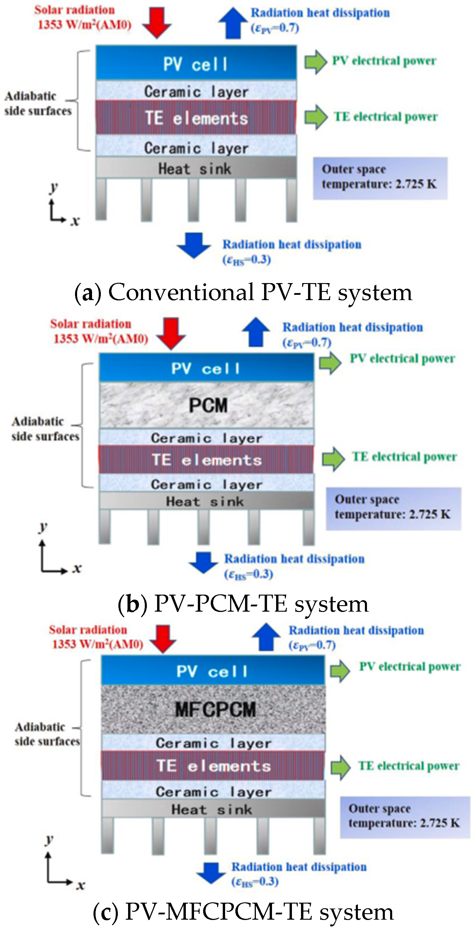
Figure 3.
The schematic of the PV-MFCPCM-TE physical model [11]. Reproduced with permission from Elsevier.
Figure 3.
The schematic of the PV-MFCPCM-TE physical model [11]. Reproduced with permission from Elsevier.
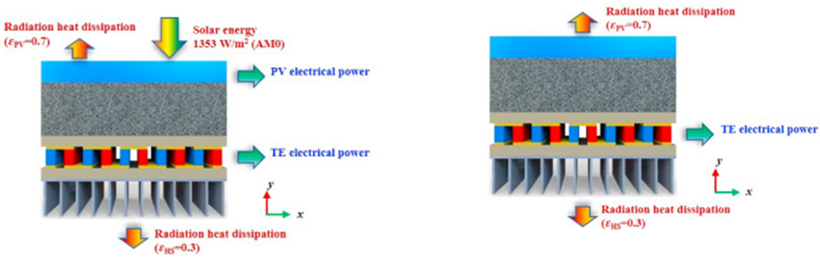
Figure 4.
PCM containment methods. Kaolin [82,83]; Sepiolite [84]; Montmorillonite [85]; Attapulgite [86,87]; Vermiculitte [88,89]; Diatomite [88,90,91]; Perlite [92,93]; Metal [94]; Silicon [95]; Graphene [96,97]; Polyethilene [98]; Acrylics [99,100]; Vinyl chloride [101,102]; Polyurethanes [103,104]; Vinly alcohol [105,106]; Maleic anhydride copolymer [107,108,109,110]; Ethylene therephtalate [111].
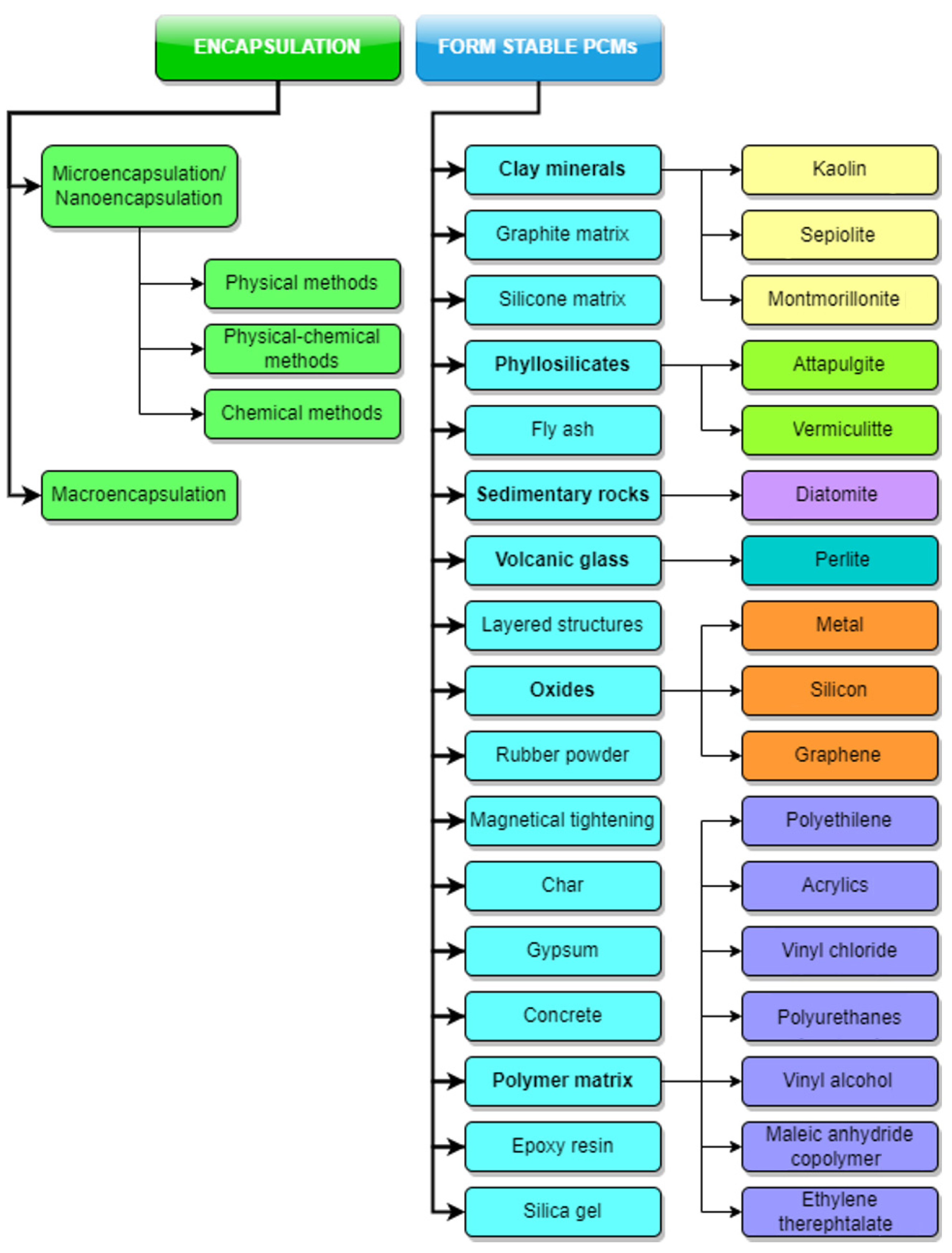
Figure 5.
Microencapsulation methods [112].
Figure 5.
Microencapsulation methods [112].

Figure 6.
Microcapsule types, Jamekhorshid [112].
Figure 6.
Microcapsule types, Jamekhorshid [112].
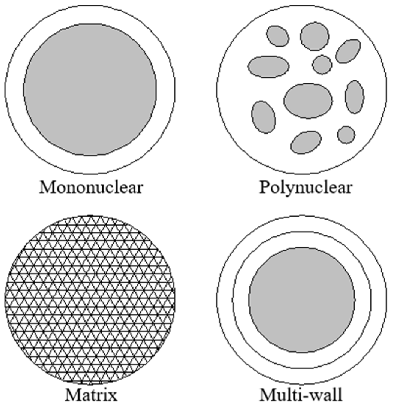
Figure 7.
Spray drying microencapsulation method process flow, Mishra [114].
Figure 7.
Spray drying microencapsulation method process flow, Mishra [114].
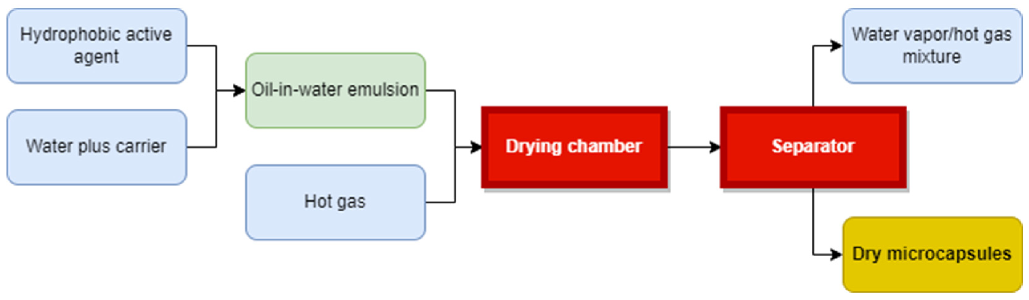
Figure 8.
Microencapsulation method by coacervation process flow, Mishra [114].
Figure 8.
Microencapsulation method by coacervation process flow, Mishra [114].
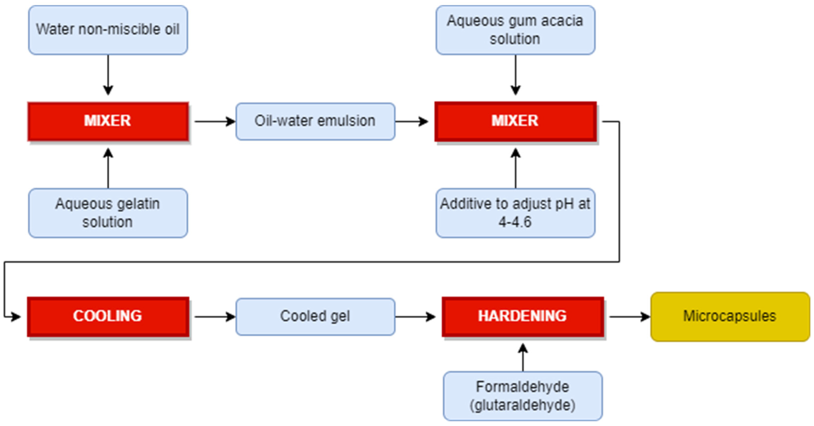
Figure 9.
SEM images of PCM microcapsules: spray drying (left) and coacervation (right), Zhang et al. [115]. Reproduced with permission from Elsevier.
Figure 9.
SEM images of PCM microcapsules: spray drying (left) and coacervation (right), Zhang et al. [115]. Reproduced with permission from Elsevier.

Figure 10.
Sol-gel method: Obtaining microencapsulated n-octadecane with silica wall using sodium silicate as precursor [117]. Reproduced with permission from Elsevier.
Figure 10.
Sol-gel method: Obtaining microencapsulated n-octadecane with silica wall using sodium silicate as precursor [117]. Reproduced with permission from Elsevier.
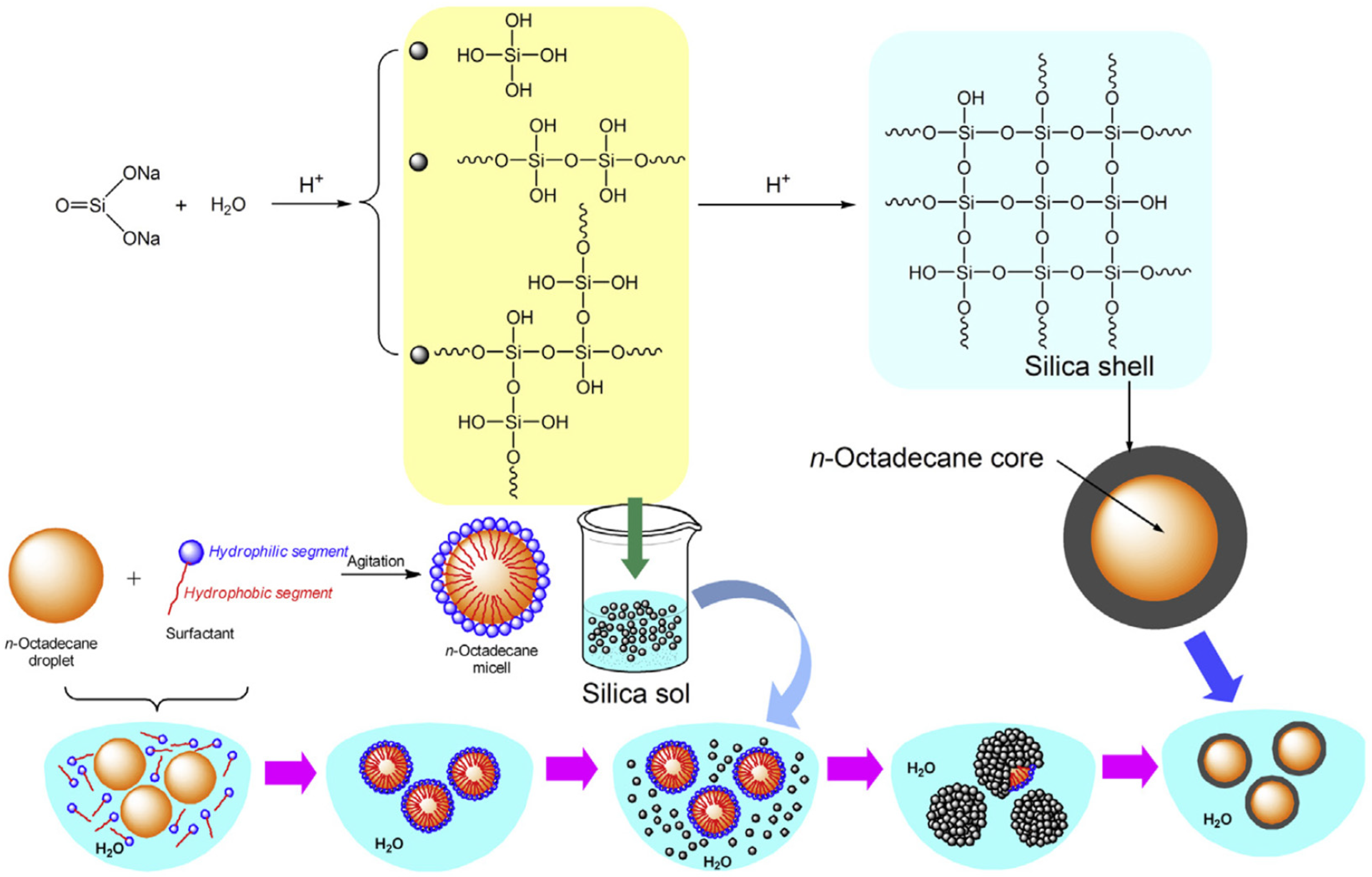
Figure 11.
The PSD (left) and SEM image (right) of PMMA/n-hexadecane microcapsules produced using allyl-methacrylate [118]. Reproduced with permission from Elsevier.
Figure 11.
The PSD (left) and SEM image (right) of PMMA/n-hexadecane microcapsules produced using allyl-methacrylate [118]. Reproduced with permission from Elsevier.
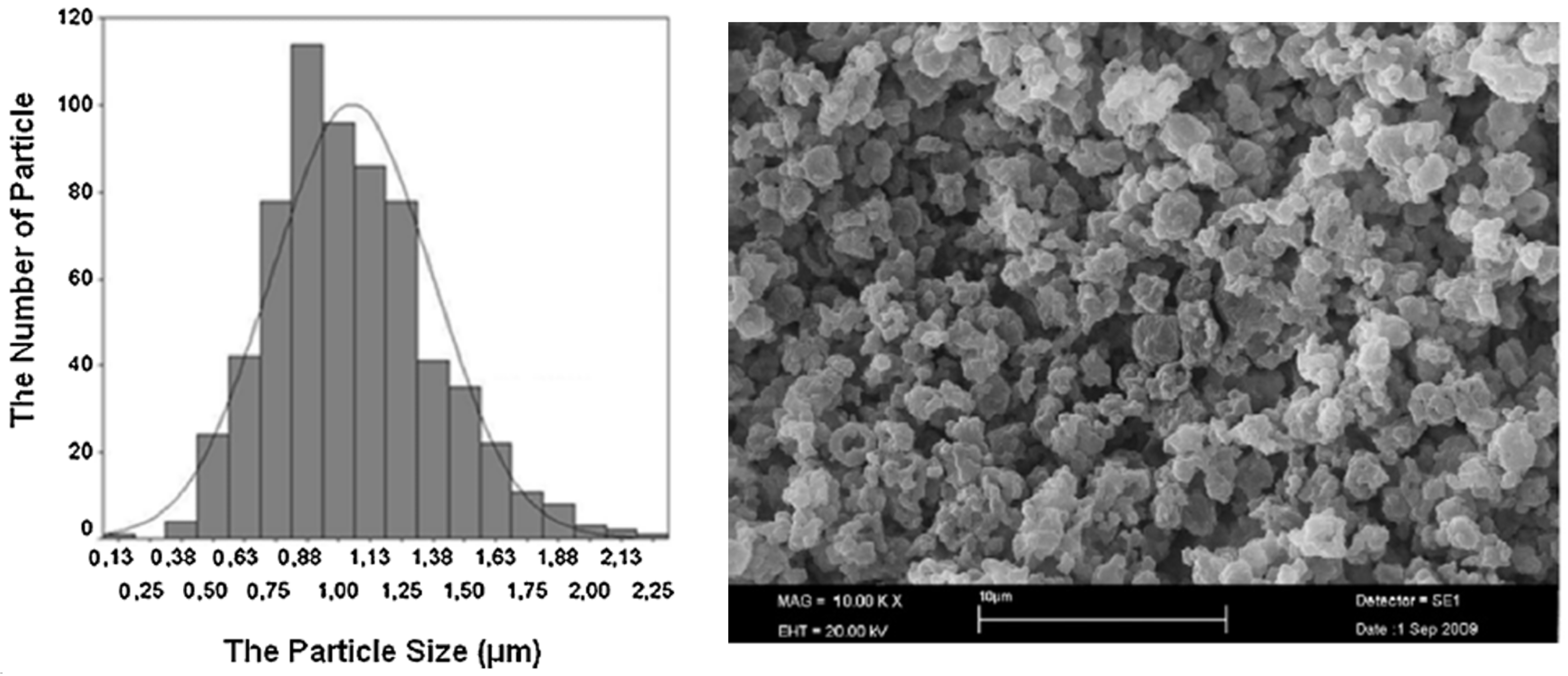
Figure 12.
Formation of microencapsulated PCMs with n-octadecane as core and resorcinol-modified melamine-formaldehyde shell through the in situ polymerization method [120]. Reproduced with permission from Elsevier.
Figure 12.
Formation of microencapsulated PCMs with n-octadecane as core and resorcinol-modified melamine-formaldehyde shell through the in situ polymerization method [120]. Reproduced with permission from Elsevier.

Figure 13.
Standard shape of the hollow space (HS) to be filled with PCM. (1) Large rectangular HSs; (2) cylindrical HSs; (3) rectangular HSs aligned with the long axis; (4) small cylindrical HSs; (5) small rectangular HSs; (6) rectangular HSs aligned with the short axis.
Figure 13.
Standard shape of the hollow space (HS) to be filled with PCM. (1) Large rectangular HSs; (2) cylindrical HSs; (3) rectangular HSs aligned with the long axis; (4) small cylindrical HSs; (5) small rectangular HSs; (6) rectangular HSs aligned with the short axis.
Figure 14.
Clay bricks and PCM macro-capsules integration, Silva et al. [133] (reproduced with permission from Elsevier).
Figure 14.
Clay bricks and PCM macro-capsules integration, Silva et al. [133] (reproduced with permission from Elsevier).
Figure 15.
PCM macro-encapsulation design challenges and solutions.DS1: [129]; DS2: [126]; DS3: [138]; DS4.1: [139,140]; DS4.2: [141]; DS4.3: [142]; DS4.4: [143]; DS4.5: [74]; DS4.6: [40]; DS5: [144]; DS6.1: [145]; DS6.2: [146]; DS7: [147].

Figure 16.
Commercially available PCM macro-capsules: spheric (left), flat containers and bags (right), Mehling et al. [148]. Reproduced with permission from Elsevier.
Figure 16.
Commercially available PCM macro-capsules: spheric (left), flat containers and bags (right), Mehling et al. [148]. Reproduced with permission from Elsevier.

Figure 17.
Form-stable PCMs: microencapsulated PCM bound to the surface of textile fibres (left); integrated into textile fibres (middle); plate-shaped composite material with embedded PCM (right), Mehling et al. [148]. Reproduced with permission from Elsevier.
Figure 17.
Form-stable PCMs: microencapsulated PCM bound to the surface of textile fibres (left); integrated into textile fibres (middle); plate-shaped composite material with embedded PCM (right), Mehling et al. [148]. Reproduced with permission from Elsevier.

Figure 18.
Preparation of the Kaol-nanotubes process [82]. Reproduced with permission from Elsevier.
Figure 18.
Preparation of the Kaol-nanotubes process [82]. Reproduced with permission from Elsevier.
Figure 19.
Preparation of PEG/EG PCM [150]. Reproduced with permission from Elsevier.
Figure 19.
Preparation of PEG/EG PCM [150]. Reproduced with permission from Elsevier.
Figure 20.
TDI-HO-Pal formation process [152]. Reproduced with permission from Elsevier.
Figure 20.
TDI-HO-Pal formation process [152]. Reproduced with permission from Elsevier.
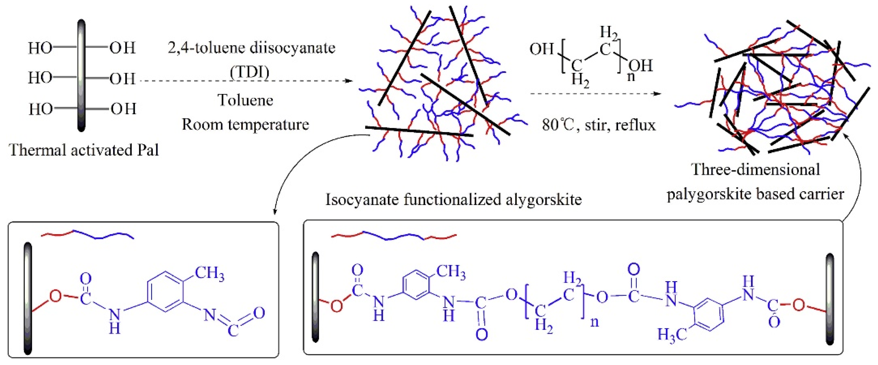

Table 1.
Passive PCM storage systems for the built environment.
| Ref. | System Design and Conditions | Findings, Conclusions |
|---|---|---|
| [24] | Gypsum wallboard impregnated with a mixture of methyl palmitate/methyl stearate with a melting range 23–26.5 C and latent heat of the phase transition 180 kJ/kg | Peak load shifting |
| [25] | A procedure to produce TES concrete (TESC) by infiltrating porous aggregates with molten PCM under vacuum conditions | The storage capacity of the TESC was comparable with that of a commercially available PCM. |
| [26] | Facade panels with double glazing combined with PCM | A more equalized energy balance in the during the day, when moderate heat gains with very low heat losses were experienced. This suggests lightweight construction appropriateness |
| [27] | Laminated wallboard with a narrow phase change temperature range. | Moderating night time temperature in a passively designed room. |
| [28] | Mixtures of CA and LA as the PCM to impregnate wallboards for building energy storage | After 360 thermal cycles the melting temperature and latent heat of the PCM wallboards showed no obvious changes |
| [29] | Phase change GW incorporating the eutectic mixture of fatty acids | A maximum of 25% of the total mass of CA/MA eutectic could be incorporated into the GW; after 1000 cycles PCM leakage occurred |
| [30] | Three-layer sandwich type wall system consisting of two PCM wallboards, impregnated with PCMs with different values of the melting point as outer layers and a middle layer of conventional thermal insulation | Annual energy savings; reduces the peak value of the cooling/heating loads. The melting point values for the two PCMs resulting in the highest value of the energy savings were identified. |
| [31] | PCM-enhanced wall system and a simplified model for the heat exchange between the indoor environment and ambient was developed | The occupancy pattern influenced the value of the PCM melting point for which maximum energy savings value was reached and; the ventilation and its pattern reduced the relative value of the energy savings. |
| [32] | PCM incorporated in concrete floors, in which solar thermal energy is stored in a concrete/PCM composite | Reduction of the maximum floor temperatures by 16% and an increase in the minimum temperatures of up to 7%. |
| [33] | PEG based shape-stabilized PCMs were successfully prepared using CNFs isolated from crab shells | The device remained opaque (∼3.5%) below the melting point of the PEG-CNF composite and became gradually transparent as the temperature of the device increased ultimately stabilizing at a transmittance value of ∼88%. CNF phase had an effect on the thermal properties of the PEG-CNF material |
| [34] | A fabrication approach of cement-based composite phase change materials (CCPCMs) by means of the water solubility of polyethylene glycol | Compared to control cement paste, the surface temperature of CCPCMs sample reduced by a maximum of 6.2 °C. |
| [35] | Latent heat storage bio-composite | The maximum energy consumption of reference building models dropped by ~530 kWh per year |
| [36] | (1) the model house without the solar Trombe wall, defined as the reference configuration; (2) the model house integrating the concrete solar Trombe wall; and (3) the model house integrating the PCM solar Trombe wall. three different climate conditions were considered for simulations: Paris-Orly, Lyon, and Nice | Similar minimizations of the one-year energy heating demand inside the bedroom, equal to roughly 20% (i.e., 20.45% of concrete storage wall and 19.90% of PCM storage wall) compared to the reference configuration. The heating energy demand in the bedroom, through application of the two storage walls (concrete and PCM) could be minimized by 20.34% in Paris, 20.20% in Lyon, and 68.10% in Nice (for the concrete storage wall) vs. the reference configuration; and by 18.79% in Paris, 19.56% in Lyon, and 55.15% in Nice (for the PCM storage wall) compared to the reference configuration |
Table 2.
Active PCM storage systems for the built environment.
| Ref. | System Design and Conditions | Findings, Conclusions |
|---|---|---|
| [37] | Macro-encapsulated PCM panel with embedded pipes as an active ceiling cooling component as opposed to commercially available radiant cooling technologies | PCM was fully discharged, the installed heat storage capacity was enough to shift the cooling demand to off-peak hours. The MEP’s specific cooling power during melting was between 5.3 and 27.7 W/m2, with 11.3 W/m2 on average over the active ceiling surface for a water supply temperature and flow rate of 20 °C and 140 kg/h, respectively |
| [38] | Solar thermal system coupling with active PCM heat storage wall. The effect of the solar collector area, hot water flow rate, initial melting temperature and thickness of PCMSW on the indoor temperature maintained by STS-APHSW was assessed. Economic comfort ratio was proposed as assessment criteria | Optimal configuration was achieved when: the solar collector area per square unit building area was 0.024 m2, hot water flow rate was 2.8 kg/s, initial melting temperature was 27 °C and the thickness of PCMSW was 20 mm. STS-APHSW can balance the time mismatch between the solar supply and demand, thus increasing the solar fraction and solar energy application potential |
| [39] | A state-space model for solar active wall-based (PCM) was proposed. The proposed numerical model was applied for a multi-layer wall with PCM Wallboards (PCMW) embedded between indoor and outdoor environments | The state-space model was able to estimate the thermal behaviour of the system, as well as the thermal characteristics of embedding PCM in the internal face of the wall. The PCM presence significantly contributed to stabilizing the indoor temperature. |
| [40] | Active PCM system installed in an eleven-storey building in Melbourne. Macro-encapsulated PCM with the phase transition temperature of 15 °C was installed in a large PCM tank. Water was used as the heat transfer fluid to extract and store cooling energy from the PCM tank. The performance of the active PCM system was monitored for 25 consecutive months, and the results were analysed on a seasonal basis | The active PCM system reduced cooling load on the chiller by 12–37% only during colder months, but remained inactive during the summer. In the case of maximum effectiveness, the PCM tank only utilized 15% of its available heat storage capacity to reduce the cooling load. The factors that contributed to the underperformance of active PCM system were identified: mismatch between designed and actual operation of the PCM system, inefficient system control, material quality, lack of maintenance staff training |
| [41] | An experiment was conducted to study the thermal performance and energy efficiency of an ASHW-PCM system. Comparative trials were then carried out to complete its systematic optimization using CFD, considering the dominating factors that may have an effect on the systematic thermal performance: the number and location of the water capillary pipes, the PCM wallboard thickness, and the heating water temperature | The test room with the ASHW-PCM system reached an energy conservation of 1.93 kWh and an indoor temperature 21.9 °C, which are higher than that of the reference room. Numerical results showed that the number of water capillary pipes mainly affects the homogenization of the ASHW-PCM wallboard surface heating temperature, and the pipe location mostly influences the heating temperature. |
| [42] | A new structure of under-floor electric heating system with SSPCM plates. The SS-PCM consisted of 75 wt.% paraffin as a dispersed PCM and of 25 wt.% polyethylene as the supporting material. | The system increased the indoor temperature of an experimental house without increasing the temperature difference; the temperature of the PCM plates was maintained at the phase transition temperature for a long period after the heaters stopped working. More than 50% of the total electric heat energy was shifted from the peak period to the off-peak hours |
Table 3.
PCM Macroencapsulation systems: materials and capsule characteristics.
| Ref | PCM | Shell Material | Temperature Range (°C) | Shell Shape | Capsule Size | PCM Mass (g) | Operational Cycles | Findings |
|---|---|---|---|---|---|---|---|---|
| [126] | Copper 99.9% | Cr-Ni | 1050–1150 | Cylinder | 2 mm | 1000 | No leakage | |
| [127] | NaNO3, NaCl–MgCl2 | Stainless steel 304. Carbon steel 1018 | 350–490 | Cylinder | 50.8, 25.4 mm(Ø) 127, 50.8 mm (height) | 269.9 28.8 23.9 284.6 282.5 | 50 | Storage performance maintained |
| [128] | NaNO3 KNO3 | AISI 321 | 160–270 | Cylinder | 27.3, 75, 39 mm(Ø) 27.7, 77, 37 mm (height) | 5000 | No shell cracking | |
| [129] | Paraffin | Steel | 0–36 | Rectangular prism | 30 × 17 × 2.8 cm | 48 h | No leakage | |
| [130] | NaNO3, KNO3, NaNO3–KNO3, NaNO3–KNO3–LiNO3 | Polytetrafluoroethylene-Ni | 120–350 | Spherical | 27.43 mm | 17.4 | 2200 | No leakage |
| [131] | Paraffin | Aluminum | 30–49.2 | Cylinder | 29 mm(Ø) 70 mm (height) | 35 | No leakage at 90 °C |
Table 4.
PCM impregnation into the support material. Methods and materials.
| Reference | Method | Adsorption Rate | Support | PCM |
|---|---|---|---|---|
| [158] | Vacuum | 85% | Porous carbon | PEG |
| [159] | Sintering | NaCl, KCl, MgCl2 | Eutectic salt chloride | |
| [160] | Adsorption | 81% | Expanded graphite | K2HPO4⋅3H2O– NaH2PO4⋅2H2O–Na2S2O3⋅5H2O–H2O |
| [161] | Adsorption | - | Expanded graphite | KNO3-LiNO3-Ca(NO3)2 |
| [162] | Solution impregnation | 82% | Expanded graphite | LiNO3–KCl, LiNO3–NaNO3 LiNO3–NaCl |
| [95] | Vacuum-assisted melting infiltration | 97% | Graphene oxide | PEG-6000 |
| Hydrothermal reductio | 86% |
Publisher’s Note: MDPI stays neutral with regard to jurisdictional claims in published maps and institutional affiliations. |
© 2022 by the authors. Licensee MDPI, Basel, Switzerland. This article is an open access article distributed under the terms and conditions of the Creative Commons Attribution (CC BY) license (https://creativecommons.org/licenses/by/4.0/).
Share and Cite
MDPI and ACS Style
Diaconu, B.M.; Cruceru, M.; Anghelescu, L. Phase Change Materials—Applications and Systems Designs: A Literature Review. Designs 2022, 6, 117. https://doi.org/10.3390/designs6060117
AMA Style
Diaconu BM, Cruceru M, Anghelescu L. Phase Change Materials—Applications and Systems Designs: A Literature Review. Designs. 2022; 6(6):117. https://doi.org/10.3390/designs6060117
Chicago/Turabian StyleDiaconu, Bogdan Marian, Mihai Cruceru, and Lucica Anghelescu. 2022. "Phase Change Materials—Applications and Systems Designs: A Literature Review" Designs 6, no. 6: 117. https://doi.org/10.3390/designs6060117