
Effect of Interference Size on Contact Pressure Distribution of Railway Wheel Axle Press Fitting

1
Faculty of Mechanical Engineering, Jimma University, Jimma P.O. Box 378, Ethiopia
2
Faculty of Science and Technology, University of Stavanger, N-4036 Stavanger, Norway
*
Author to whom correspondence should be addressed.
Designs 2023, 7(5), 119; https://doi.org/10.3390/designs7050119
Submission received: 24 July 2023
/
Revised: 10 October 2023
/
Accepted: 17 October 2023
/
Published: 22 October 2023
(This article belongs to the Section Mechanical Engineering Design)
Abstract
:Mechanical couplings in engineering usually use interference fits to connect the shaft and hub. A railway wheel axle is a press fit that is connected by interference and can be subjected to bending stress. In loaded press fits, a high concentration of contact stresses can be generated in the area of the axle-fillet beam, which in most cases leads to the failure of the axle due to fatigue and fretting fatigues. Therefore, it is crucial to determine the ability of the press-fitted joints to provide sufficient frictional resistance that can withstand the loads and torques by evaluating the safety factor, especially when the mechanical or structural system is loaded. In this paper, the contact pressure and stress distribution along the radius of the wheel axle are studied using the analytical calculation of Lame’s equation, and the numerical method used is by ANSYS software. It was found that interference fits have a great influence on the connection strength of interference fits, which are directly related to the contact pressure. Increasing the interference increases the contact pressure, which allows higher torque and load capacity to be transmitted. The finite element analysis showed good agreement for the highest interference value of 230 µm with a relative error of 1.4%, while this error increased to the maximum relative error of 14.33% for a minimum interference of 100 µm.
1. Introduction
Interference-fit joints are commonly used in engineering constructions for connecting the shaft and the hub [1]. Fit is the degree of tightness or looseness of two connected mechanical parts by a radial pressure due to the interference size at their interface diameter [2]. In addition to tightness or looseness, the movement of the two components can be determined by the size of the clearance, i.e., whether the parts can move independently from each other, or are temporarily or even permanently joined as solids to make both mating parts move together [3]. Though interference is an effective way to transmit higher torques, its disadvantage is that in some typical configurations, the disassembly is not easy, or, in some cases, it is impossible.
An interference fit is a means of fastening two parts and it is achieved by friction after the parts are assembled. The interference can be achieved either by press fit or shrink fit methods. A press fit (also called force fit) is obtained by forcing a shaft into a smaller hole by pressing it together using a hydraulic ram, while a shrink fit is produced either by heating the members having the hole and allowing it to cool to the shaft under an ambient temperature, or by cooling the shaft before assembly. Both enable changing the relative size of the mating parts at the time of assembly [4]. Shrink fits are used to join small- and medium-sized parts to reduce the need for a large interference fit and reduce contact stress. Press fits are better suited for assembling larger parts where the use of shrink fits will cause damage (higher temperatures can cause grain growth and the loss of desired mechanical properties). Shrink-fit joints that are assembled by the use of heat can experience residual stress which leads the contact mate to fatigue [5].
The interference fit is widely used in many industrial fields for its high ability to transmit an axial force or torque between a shaft and hub with the help of friction effects [6]. They are commonly used for heavy machinery and general machinery that can carry a heavier load, as they provide a solid connection that may require significant force or potential machine operations to separate them, making press-fit more advantageous than key or pin connections [7]. They have excellent load-bearing ability under both static and dynamic loading conditions, so have been used in many engineering fields [8]. Since there are no additional fasteners, these connections are also simple and quick to make, and therefore relatively inexpensive. The strength of such assemblies is influenced by several factors, including the degree of interference, the physical dimensions, material qualities, surface roughness, and geometrical defects of mating elements [9]. Typical applications of interference fits are found in railway wheelsets [10], turbine disks, crankshafts-belt, pulleys, flanges, shaft bearings, and gear assemblies [11]. Increased interference fit increases the connection’s strength to its maximum, and rigidity has a significant impact on the strength of the joint when the hub and shaft are manufactured from different materials. To increase the strength of the shaft, it is necessary to increase the thickness of the shaft and decrease the thickness of the hub [12]. The relative displacement of press-fitted parts is therefore prevented by the forces due to the elastic compressive deformation in the shaft and tensile deformation in the hub, which are proportional to the extent of interference between the joints, and this is used to control the failure of the vibration displacement [12].
In railway applications, press-fitted parts such as wheels or a driving gear unit are installed in axles with interference fit, i.e., they have slightly smaller diameters than the axle seats. In press-fitted connection, higher radial pressure is generated at the contact interface (the outer diameter of the shaft and the inner diameter of the hub), making the mating parts tightly hold each other, and it is used to transmit torque or movement [13]. The way parts are held together can vary depending on interference at the wheel axle [14]. In particular, one of the disadvantages of interference fit joints in railways is the high preload of the parts around the contact area (interference fit), which occasionally leads to the failure of parts due to fatigue or fretting fatigue, which often initiate cracks at the interference fit [15] and axle fillet roots [16]. Since the failure of an axle, wheel, or bearing inevitably leads to the derailment of a train, the study of wheelsets is of paramount importance for the safe operation of trains [17]. The wheelset is an extremely important component of the railway wheel and axle system, and it is critical as the contact easily initiates crack [18]. Interference also has a significant impact on contact pressure, which plays a major part in fretting fatigue [19]. Increasing interference can result in higher contact pressure and also reduce the friction coefficient. This friction reduction is caused by the local yield of material and makes small cracks between the contact surfaces, which have a negative influence on the connection strength [20]. Once assembled, the interference fit could fail due to fretting wear and fretting fatigue, which is a type of fatigue where the parts have relative movement between compressed parts that bring wear. The failure is the gradual deterioration of parts where fretting is worn, which enables the loss of contact pressure between contacting pairs [21].
In railway systems, research on wheel axles began after a train broke its axle, causing a derailment in the United Kingdom. This encouraged a new area of research in railroads into axle safety and the application of a hierarchical approach to safety based on the “safe life” method. To detect rail flaws before a rail failure, railroad companies conduct regular inspections of their rails using nondestructive technologies (NDE). The NDE techniques commonly used for rail maintenance are eddy current inspection, visual camera, magnetic inspection, and ultrasonic inspection, to name a few. Among these techniques, the ultrasonic inspection-based technique is the most commonly used for performing routine inspections [22].
Axle failures can be caused by mechanical loads, electrical arcing, wear, and corrosion [23]. Most often, they are subjected to a large number of repetitive loading cycles, transitioning from a compressive state to a tensile state of equal magnitude. The press fit between axles and wheels can introduce compression stresses beneath the press fit and axial tensile stresses in the fillets, which could contribute to the fretting corrosion fatigue due to the micro-slip between the press-fitted parts after several cycles. Fretting is damage that occurs when short-amplitude reciprocating sliding load between contacting surfaces is sustained for a large number of cycles that results in two forms of damage: (1) surface wear and (2) the deterioration of fatigue life. Fretting damage can be classified into fretting fatigue, fretting wear, and fretting corrosion. In the case of fretting wear, the associated production of debris leads to a loss of fit between contacting surfaces [24]. The maximum contact pressure within the mating surface is the main parameter controlling the development of fatigue crack initiation at the wheel seat, and friction also has tiny axial flaws for failure [25]. In addition, compressive residual stresses induced by surface hardening can bring about fretting fatigue at the seat [6].
The possibility of relative motion is controlled by the friction coefficient, the normal pressure, and the surface roughness; therefore, one could argue that the contact pressure at the inlet to the contact should be high. The most dangerous part of the wheel axle press fit is the edge of the contact between the axle and the wheel hub, where fatigue cracks can occur due to the high probability of stress generation. Due to the discontinuities in contact geometry, stress concentrations occur at the contact edges of the axles and failure starts in the areas where these stress accumulations are present [14]. Stress accumulation is the result of loading geometry, surface quality, corrosion effect, material failure, and the heterogeneity of the microstructure. In addition, the contact edge area is vulnerable to fatigue cracking as a result of mutual slip under external rotational bending and vibration stresses. The simultaneous actions of contact pressure and relative displacement between the contact surfaces can damage the contact surfaces of the mating components in the forms of wear, oxidation, and crack nucleation [26]. So, to avoid all these cases, the study of the contact pressure between the interference fits during the assembly of the parts is crucial, since the slippage and displacement of the parts can be calculated based on the size of the interference.
Based on the above literature, studies on the interference fit are very important for the design, safety, and efficiency of the interference fit, since the interference fit in the joint is used to control the torque transmission capability and residual stress of the interference fit. In the control of cracks caused by stress concentration, the magnitude of the pressure that develops between the press fit is studied using theoretical and numerical models along the contact area to ensure an adequate contact area, contact pressure, and equivalent stress, which are used to determine the strength of the parts by using interference fits. In this paper, the analytical calculations based on Lame’s equation and numerical investigation using the finite element method (FEM) are carried out for the railway wheel axle interference. The goal is to see the effect of interference on the contact pressure distribution of a wheelset connection having 22.5 tons of carrying capacity.
2. Theoretical Analysis of Press-Fitted Joints
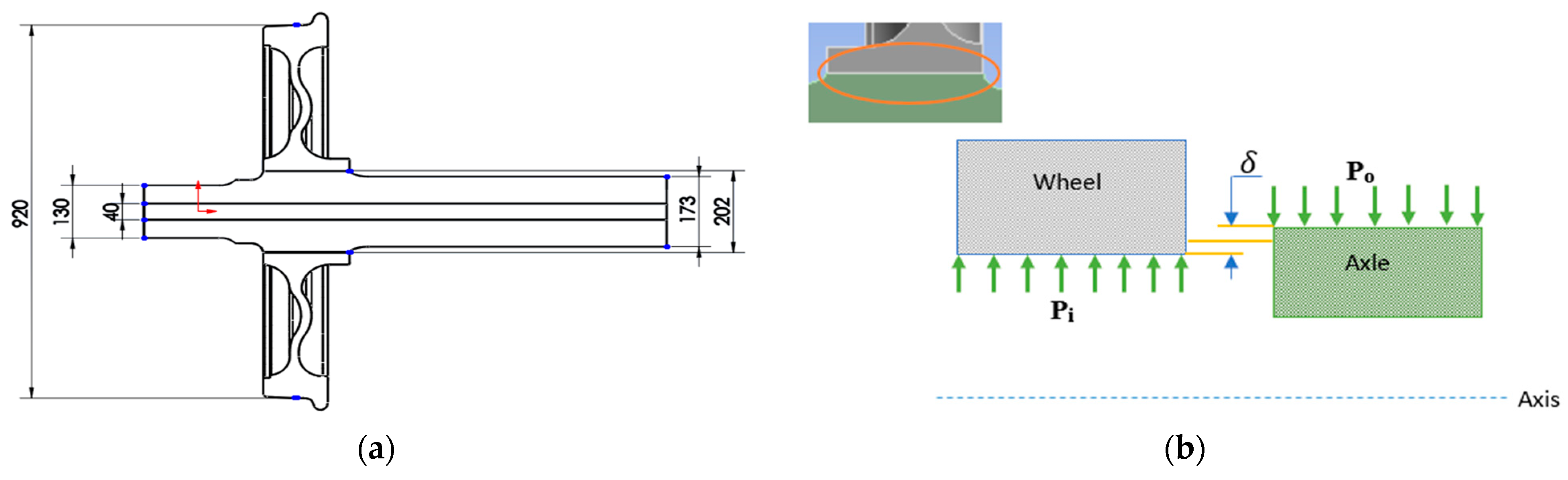
The wheelset can be formed by press-fitting or shrink-fitting depending on the force applied to them. In press-fitting, pressure is applied to the wheel hub to force it onto a slightly larger diameter axle, thus leading to contact. In press-fitting contact, there is external pressure which acts on the axle wheel seat, and internal pressure acts on the wheel hub, which is equal and opposite at the contact surface in the wheelset, when it is assumed that the axle and wheel are composed of the same material. The outboard wheelsets used have great design freedom with a large space envelope to distribute the moment through the axle that needs more attention in the design of interference. The design philosophy is based on Lame’s solution for the thick-walled cylinders taking a state of plane stress both in the axle and in the wheel [27]. The calculation of pressure for the design can depend on the inner and outer diameter of the wheel and axle, and the interference size, which can change the value the most. The geometric model of the wheel and axle assembly is illustrated in Figure 1a with the dimensions used for analysis.
where P = contact pressure after assembly, E = elastic modulus, δ = interference, rw = outer wheel diameter, ra = outer radius of the axle, and ria = inner radius of the axle.
For the wheel and axle having different materials and for the axle of a hollow type, the pressure distribution given by Equation (1) is not valid. Instead, Equation (2) is used.
where P = contact pressure after assembly, Ew = wheel elastic modulus, Ea = axle elastic modulus, δ = interference, rw = outer wheel diameter, ra = outer radius of axle, and ria = inner radius of the axle.
The contact pressure in the thick-wall cylinder is used to compute the radial stress and the tangential stress depending on the applied pressure, which is the internal and external pressure acting on the cylinder. The equation to compute this stress distribution is given by Equations (4) and (5).
where δ = interference; rw = wheel radius; ra = axle radius; ria = axle inner radius; E = Young’s modulus; ν = passion ratio.
The above equations (Equations (3) and (4)) can be computed in the cylindrical applied pressure case where only one cylinder is considered. But, in the case of wheel axle press-fit connection, as depicted in Figure 1b, there are two applied pressures which are an inner pressure acting on the wheel and an outer pressure on the axle, so the above equations are modified in the case of a press fit.
2.1. Wheel Internal Pressure
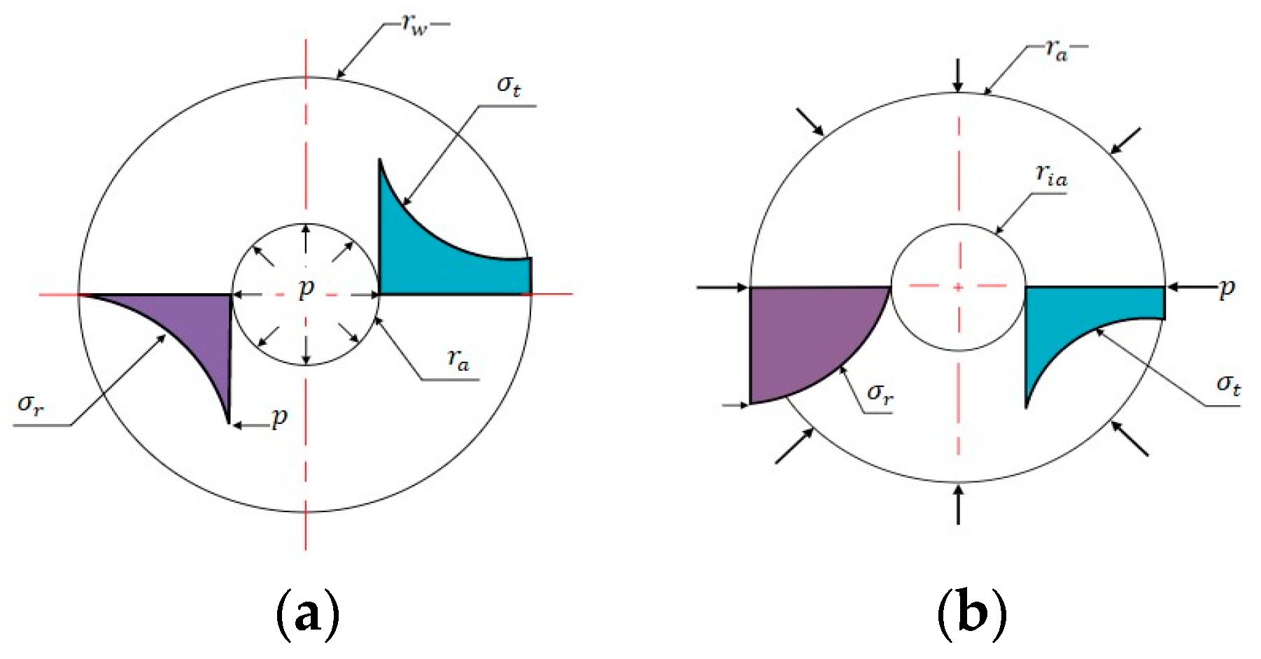
The railway wheel hub is subjected to an internal pressure from that of the axle while the external pressure is zero (Figure 2a). In the case of wheel internal pressure, radial stress is equal to the opposite, with a minus sign, of the pressurization at the inner diameter and zero in outer diameter as there is no pressure applied on the outer surface.
In this case, the radial () and tangential or hoop () stresses are expressed as
where pi = internal pressure (MPa), x = radial distance (mm), rw = wheel radius, and ra = axle radius
2.2. Axle External Pressure
The railway axle is subjected to the external pressure (po) from that of the wheel and bearing so that the internal pressure is zero, as shown in Figure 2b. In the case of axle external pressure, the radial stress is equal to the pressure at the outer diameter, but with a minus sign, and zero at the inner diameter as there is no pressure applied at the inner surface. This stress distribution is given by
where po = outer pressure (MPa), x = radial distance (mm), ra = outer radius of axle, and ri = inner radius of axle.
3. Material Composition and Modeling Approach
3.1. Material of Railway
Railway wheels and axles are usually made from material compositions having a greater resistance to wear, hardness, and ductility such as carbon, manganese, silicon, chromium, and molybdenum alloys. The Ethio-Djibouti railway is a Chinese product, so according to the China National Railway standard, which is the International Union of Railway (UIC), the material used for the wheel hub is R7T steel grade, and for that the axle A1N is used (Table 1). The mechanical properties of the materials used are also listed in Table 2.
3.2. Tolerance
Tolerance is a dimension’s total permissible deviation form (acceptable measurement range from the basic or nominal dimension). In other words, it is the difference between a measure’s upper and lower limit. Since it is impossible to obtain everything with an exact measurement, tolerances are used on production drawings to control parts, ensuring the stability and reliability of the assembly. The satisfactory operation of a machine depends largely on the proper fit between the various machine elements. Therefore, tolerances are used to control deviations in material properties, inherent inaccuracies in production machines, and operator errors [28]. The interference between the wheel and hub can be calculated via the tolerance fit method using the nominal diameter (202 mm) of the axle, which was taken from the UIC standard. Using this nominal diameter, the standard tolerances for the hole and axle can be calculated, which are 0.072398 mm and 0.046335 mm for hole grade 8 and axle grade 7 selected for force fit on ferrous parts for permanent assembly. The parts in the assembly have a tolerance of 202 H8/t7, with the calculated lower and upper limits shown in Table 3.
3.3. Finite Element Analysis
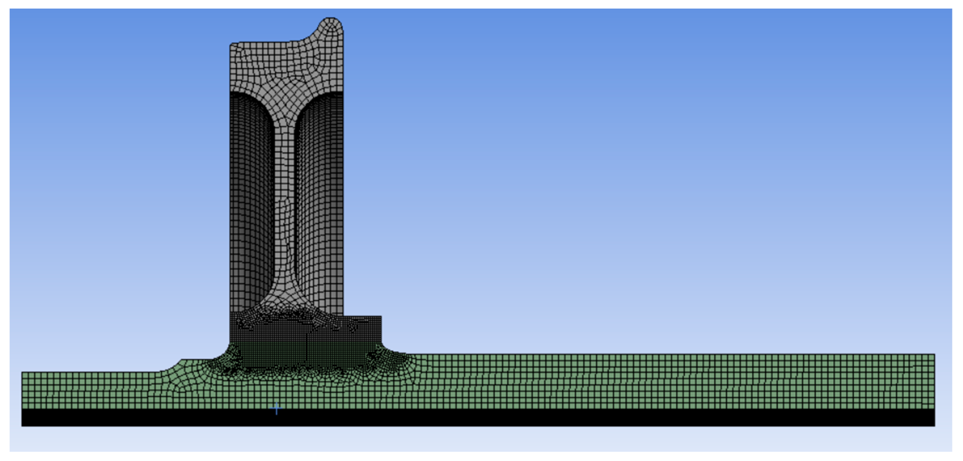
Finite element analysis was used in this study to analyze the press-fit interference’s stress distribution and deformation on the railway wheel and axle. The geometric model of the wheel and axle assembly is modeled using the finite element method as shown in Figure 3 and ANSYS v 22.1 for the simulation system used. The contact algorithm, mesh size, and simulation options are taken into consideration using the axisymmetric condition of the model, and a quarter of the connection was modeled with hexahedral elements to reduce the computational time. In this study, the rim-type wheel with a 920 mm diameter and 202 mm inner diameter was used with the same dimensions used in Sitarz et al. [29], which were also used in Marshall et al.’s [30] experimental work. Hollow-type wheel axles with an inner diameter of 40 mm and an outer diameter of 202 mm and a total length of 2180 mm have a contact length of 180 mm between the wheel and the axle mount. For both the material properties of the wheel and the axle, a linear elastic material behavior with a Young’s modulus of 210 GPa and Poisson’s ratios of 0.3 and 0.26 for the wheel and axle, respectively, is defined. The maximum and minimum interference used between the axle and wheel are 230 µm and 100 µm, respectively.
The wheel and axle contact area meshed with a contact sizing mesh of 1 mm element size between contact until the stress and contact pressure changed, and this was lower than 2% with 5 mm mesh for the others to reduce the computational time. The total numbers of elements and nodes are 650,624 and 2,755,675, for the wheel and axle, respectively. The contact surface interaction between the axle wheel seat and wheel hub was defined using a frictional contact algorithm: namely, the wheel hub surface was the target body, and the axle wheel seat surface was the contact body. A contact interaction property was defined as an Augmented Lagrange, and the coefficient of friction was set to 0.2 to ensure tangential behavior, and the normal stiffness value of 0.01 was used in the analysis. The quarter model of the geometry is used in simulation with the axisymmetric to obtain the exact result by reducing computational time.
The geometric dimensions of the shaft and hub are shown in Figure 3. The element size was set as 0.1 mm. For the axisymmetric characteristic of the model, only a quarter of the connection was modeled with hexahedral elements.
4. Discussion of Results
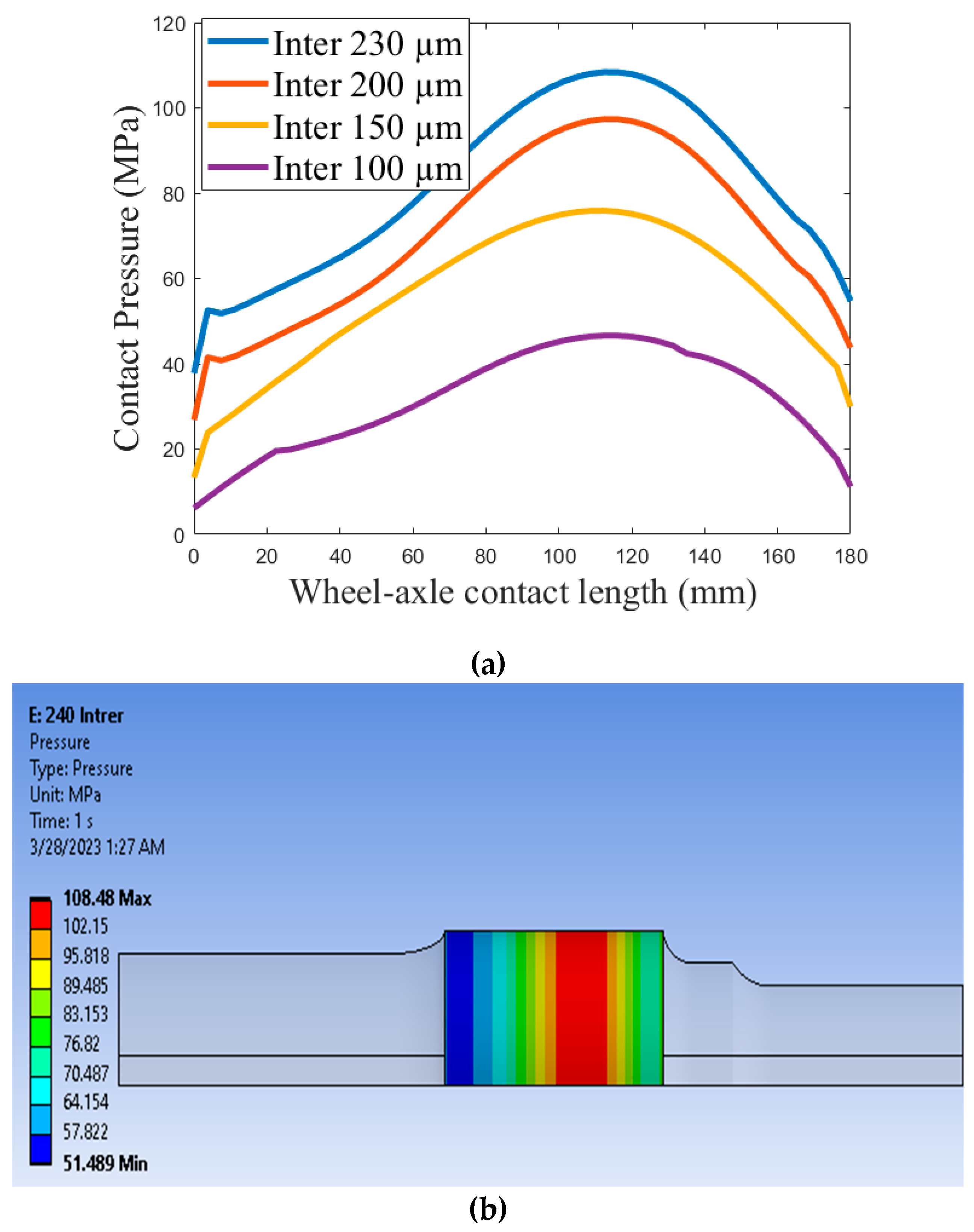
In this study, the contact pressure distribution was calculated using Equation (1) over the contact area, and the result found from the equation is listed in Table 5 for the sake of numerical comparison. The pressure distributions for different values of the interference and the distribution along the contact length are plotted in Figure 4, and a higher contact pressure is found at the contact middle length of 70 mm away from the edge wheel flange. Pressure distribution that is found using Equation (1) is also used for the computation of the radial and tangential stress along the radius by Equations (5) and (6), for internally applied pressure in the case of the wheel and Equations (7) and (8), and for the externally applied pressure in the case of the axle. The analytical result calculated using Lame’s equation and the numerical result from ANSYS are compared for different interference values with relative error. The relative error of maximum interference of 230 µm (or 0.23 mm) pressure is 1.40% for analytical and numerical, and the error increased to 14.33% for the minimum interference of 100 µm (or 0.1 mm), which is also acceptable as it is less than 15%. When compared with the work of Marshall et al. [30], which was studied for 250 µm interference with a surface roughness of 1.5 μm for steel material, studied by the same author in 2006 [31], and using ultrasonic inspection for measuring the contact pressure of the wheel hub-axle press fit, a contact pressure of 111 MPa was found, almost equal to the analytical one, but lower due to the roughness effect. For the numerical and analytical case, the relative error increases when the interference is decreased for the same mesh.
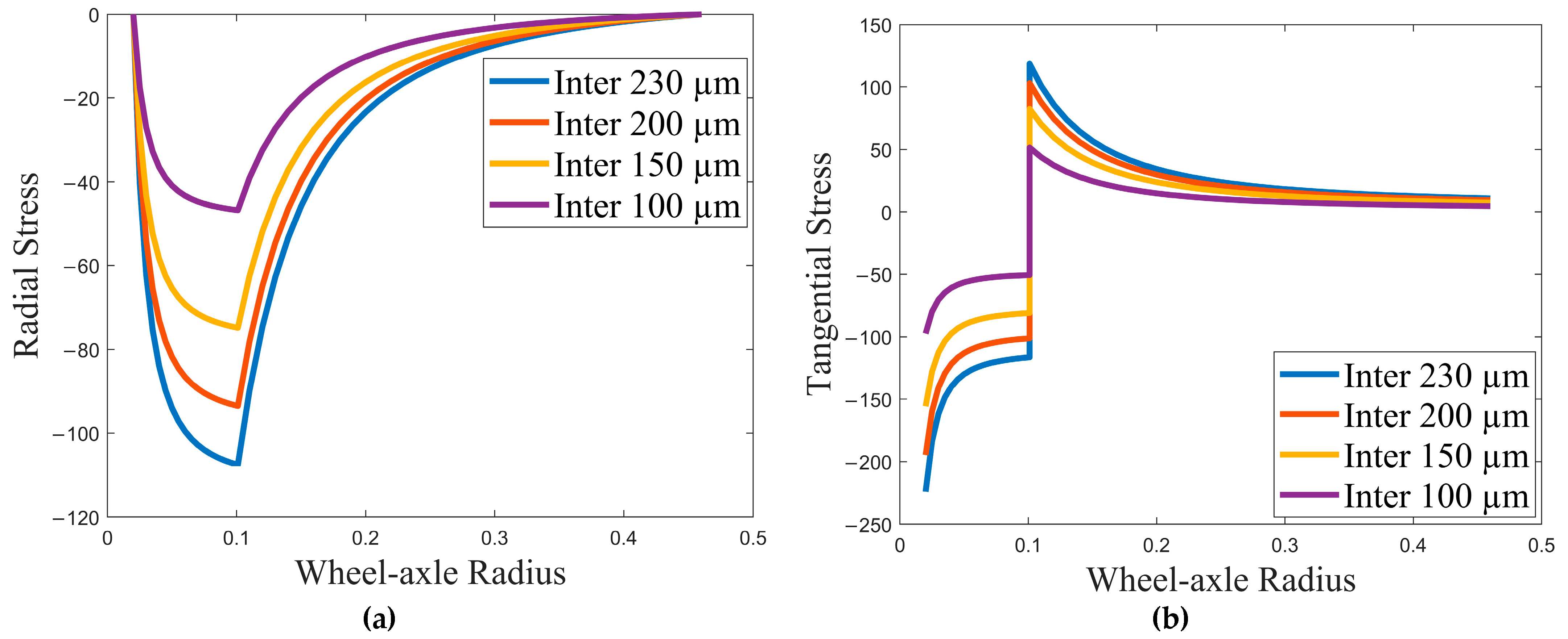
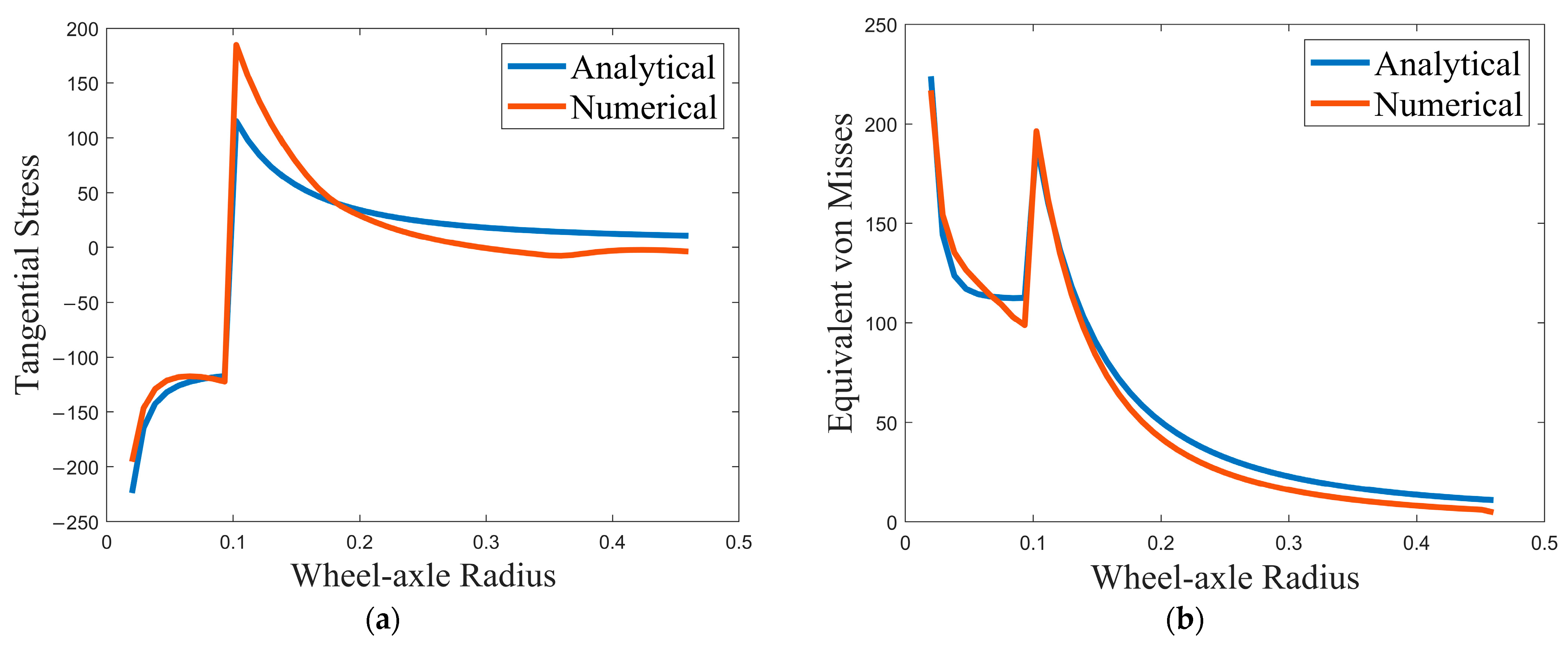
Analytical results for interferences of 230 µm, 200 µm, 150 µm, and 10 µm are calculated using Lame’s equation and compared to the simulated results, as shown in Figure 5a,b and Figure 6a for radial stress, tangential stress, and von Mises stress, respectively. As can be seen from the figures, all radial, tangential, and von Mises stresses increase with increasing interference. At the interface of the wheel axle, radial stresses have minimum value and maximum tangential stresses. It can be observed that the von Mises stress is maximum at the inner radius of both the wheel and axle. The analytical and numerical results are also compared for the interference at 230 µm, the results of which are shown in Figure 6b and Figure 7a,b for the radial stress, tangential stress, and von Mises stress, respectively. As depicted in Figure 6b, for radial stress, the plot of the numerical result is not linear (as shown in the encircled expanded view) because of the effect of the wheel width change at a distance of 140 mm radii from the wheel hub to the wheel plate. On the other hand, the analytical result is linear for the wheel since analytical calculation cannot consider the change in width but considers it as a uniform cylinder over the given radius. As a result, the radial stress obtained by the numerical analysis significantly deviated from the analytical results (indicated with red circle in Figure 6b. The radial stress is zero at the inner surface of the hollow axle and the outer surface of the wheel since they are unpressurized surfaces. Tangential stress is also at its maximum at the outer surface and minimum at the inner surface of the axle. But, it is maximum at the inner surface and minimum at the outer surface of the wheel.
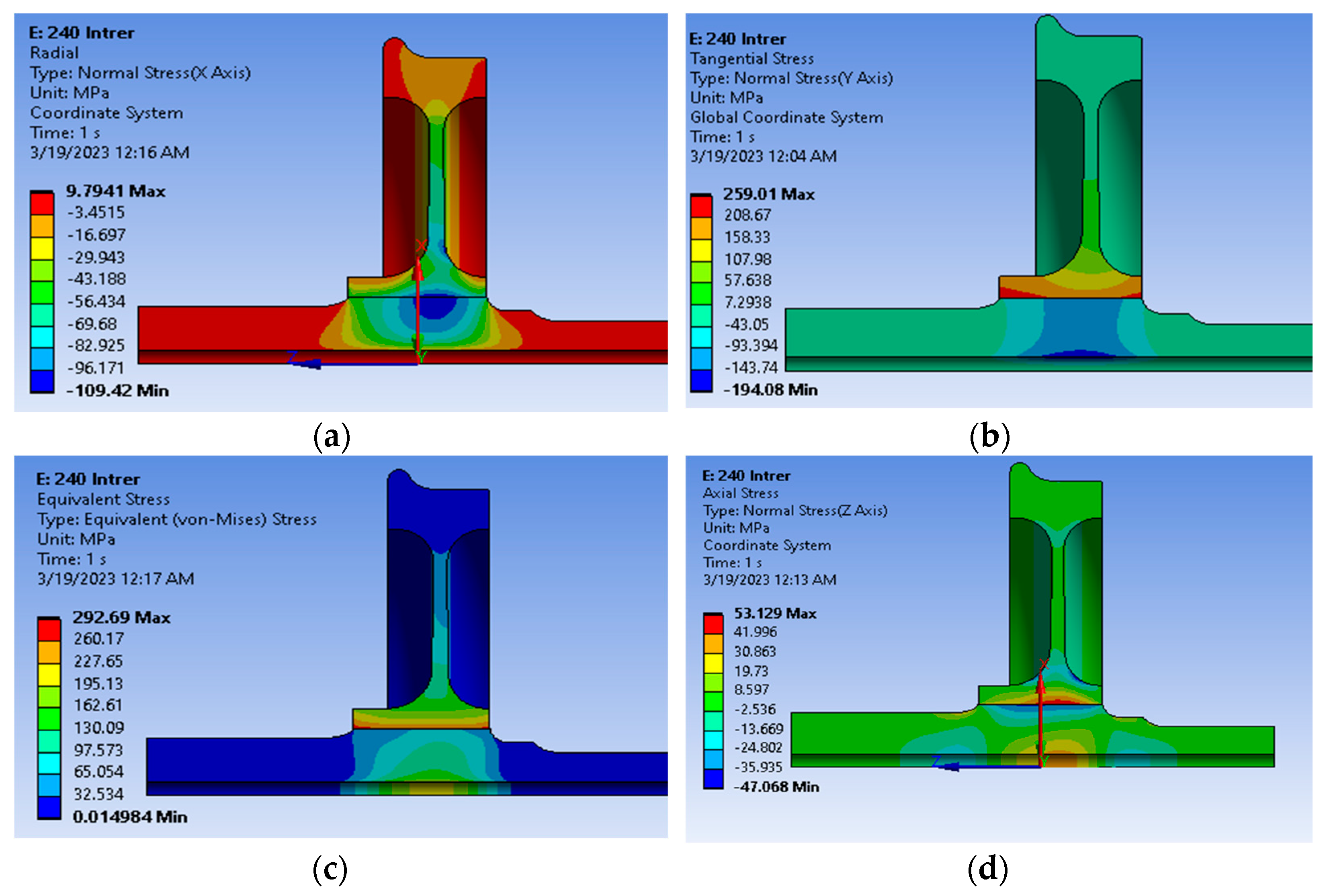
The results from the finite element analysis on the wheel and axle assembly are shown in Figure 8. As can be seen in Figure 8a, the minimum radial stress is at the interference fit, which confirms that the maximum tangential stress and von Mises equivalent stresses of the analytical results are at the wheel hub bore, as can be seen in Figure 8b and Figure 8c, respectively. The axial stress (Figure 8d) also appears at the wheel hub, but the value is much lower than the equivalent von Mises stress. The deformation of the interference fit decreases with increasing interference since the pressure between the joints is higher at this location. The maximum deformation, as can be observed from Figure 9, at 230 µm interference is 13 µm.
5. Conclusions
In this study, results from a numerical analysis using the FEM tool and calculated analytically using Lame’s equation of a thick-wall cylinder for contact pressure are compared. The results agreed well with a 1.4% relative error for the largest interference (diametral difference), which is 230 µm, while the relative error of contact pressure increased with a decreasing contact diameter by 14.33% relative error for the smallest interference of 100 µm. In general, this implies that the results are considerably acceptable. So, for the press-fitting analysis of the wheel and axle, Lame’s idea for a thick-walled cylinder is effective. From the contact pressure results, tightening pressure decreases as the interference size decreases, which shows that interference has a direct effect on the life-cycle estimation of press-fitted parts. The numerical results, in all cases, show higher values than analytical results, which can be attributed to the fact that the wheel and axle are regarded as typical cylinder surfaces, as well as the fact that the assembly parts have a complicated geometry. These findings demonstrated that the tangential stress, which was the highest of the three main stresses, was generated at the contacting surfaces of the wheel hub.
Deformation during press-fitting along the radial axis was unfavorably affected and strongly depended on the contact pressure at the wheel and axle interface. One of the study’s most important conclusions is that when interference increases, it can transfer a higher torque with high contact stresses failing at the point of stress concentration, while lower clearances cause slippage. Therefore, press-fitted components benefit from having medium clearances. Taken together, these results suggest that the press-fit effect should be accounted for in a railway axle design.
Author Contributions
Conceptualization, K.A.I.; methodology, K.A.I.; software, K.A.I.; validation, H.G.L. and Y.A.K.; formal analysis, K.A.I.; investigation, K.A.I.; resources, K.A.I.; data curation, K.A.I.; writing—original draft preparation, K.A.I.; writing—review and editing, Y.A.K. and H.G.L.; visualization, K.A.I., H.G.L., and Y.A.K.; supervision, H.G.L. and Y.A.K.; project administration, H.G.L.; funding acquisition, H.G.L. All authors have read and agreed to the published version of the manuscript.
Funding
This research received no external funding.
Institutional Review Board Statement
Not applicable.
Informed Consent Statement
Not applicable.
Data Availability Statement
Not applicable.
Conflicts of Interest
The authors declare no conflict of interest.
References
- Madej, J.; Śliwka, M. Analysis of Interference-Fit Joints. Appl. Sci. 2021, 11, 11428. [Google Scholar] [CrossRef]
- Paredes, M.; Nefissi, N.; Sartor, M. Study of an Interference Fit Fastener Assembly. In Proceedings of the IDMME–Virtual Concept 2010, Bordeaux, France, 20–22 October 2010. [Google Scholar]
- Liu, G.; Hong, J.; Wu, W.; Sun, Y. Investigation on the Influence of Interference Fit on the Static and Dynamic Characteristics of Spindle System. Int. J. Adv. Manuf. Technol. 2018, 99, 1953–1966. [Google Scholar] [CrossRef]
- Kanber, B. Boundary Element Analysis of Interference Fits. Turk. J. Eng. Environ. Sci. 2006, 30, 323–330. [Google Scholar]
- Jiang, J.; Bi, Y.; Dong, H.; Ke, Y.; Fan, X.; Du, K. Influence of Interference Fit Size on Hole Deformation and Residual Stress in Hi-Lock Bolt Insertion. Proc. Inst. Mech. Eng. C J. Mech. Eng. Sci. 2014, 228, 3296–3305. [Google Scholar] [CrossRef]
- Wang, X.; Lou, Z.; Wang, X.; Hao, X.; Wang, Y. Prediction of Stress Distribution in Press-Fit Process of Interference Fit with a New Theoretical Model. Proc. Inst. Mech. Eng. C J. Mech. Eng. Sci. 2019, 233, 2834–2846. [Google Scholar] [CrossRef]
- Ning, K.; Wang, J.; Jiang, H.; Xiang, D.; Hou, D. Multiobjective Intelligent Cooperative Design for the Multilayer Interference Fit. Math. Probl. Eng. 2019, 2019, 4789030. [Google Scholar] [CrossRef]
- Lou, Z.; Wang, X.; Wang, Y.; Wang, X.; Xu, C.; Wang, Z. Precision Assembly Method of a Kind of Small Interference Fitting Parts. Sādhanā 2019, 44, 144. [Google Scholar] [CrossRef]
- Zhao, H. Numerical Analysis of the Interference Fitting Stresses between Wheel and Shaft. Int. J. Mater. Prod. Technol. 1997, 12, 514–526. [Google Scholar] [CrossRef]
- Sarabandi, S.; Soleimani, H.; Mahmoudi, S. The 3-D Finite-Element Analysis of Press Fitting Process in Railway Wheel-Set. Sci. Iran. 2019, 26, 367–374. [Google Scholar] [CrossRef]
- Booker, J.D.; Truman, C.E. Strengthening and Weakening Mechanisms in Interference-Fitted Joints. In Proceedings of the 7th International Conference on Integrity, Reliability, Failure, Funchal, Portugal, 6–10 September 2020; pp. 405–418. [Google Scholar]
- Bhat, M.S.; Jadhav, S. Analytical Method to Determine Press-Fit Tolerance between Torque Carrying Members. In SAE Technical Papers; SAE International: Warrendale, PA, USA, 2012; Volume 8. [Google Scholar]
- Shu, Y.; Liu, Z.; Yang, G. Finite Element Simulation of Fretting Wear on Railway Axle Press-Fit Specimens. Tribol. Int. 2023, 178, 108024. [Google Scholar] [CrossRef]
- Salehi, S.M.; Farrahi, G.H.; Sohrabpoor, S.; Nejad, R.M. Life Estimation in the Railway Wheels Under the Influence of Residual Stress Field. Int. J. Railw. Res. 2014, 1, 53–60. [Google Scholar]
- Mohammad Zehsaz, P.S. The Effects of Friction Coefficeint and Interfernce on the Fretting Fatgue Strength. Int. Union Railw. 2013, 75, 71–84. [Google Scholar]
- Yamamoto, M.; Ishiduka, H. Stress Concentration of Transition Groove Induced by a Press-Fitted Part in Railway Axles. Int. J. Fatigue 2017, 97, 48–55. [Google Scholar] [CrossRef]
- Jwo, J.S.; Lin, C.S.; Lee, C.H.; Zhang, L.; Huang, S.M. Intelligent System for Railway Wheelset Press-Fit Inspection Using Deep Learning. Appl. Sci. 2021, 11, 8243. [Google Scholar] [CrossRef]
- Karlsen, Ø.; Lemu, H.G. Fretting Fatigue and Wear of Mechanical Joints: Literature Study. IOP Conf. Ser. Mater. Sci. Eng. 2019, 700, 012015. [Google Scholar] [CrossRef]
- Li, S.; He, Z.; Zhao, P. Study on the Design Method of Interference Fit between Gear and Shaft of Automobile Transmission. J. Phys. Conf. Ser. 2021, 1885, 052067. [Google Scholar] [CrossRef]
- Zhao, J.; Wang, J.X.; Yu, C.; Tang, S.Q.; Yao, J. Influence of Radial Interference on Torque Capacity of Shrink-Fit Camshaft. Adv. Mech. Eng. 2019, 11, 1687814018817640. [Google Scholar] [CrossRef]
- Pedersen, N.L. On Optimization of Interference Fit Assembly. Struct. Multidiscip. Optim. 2016, 54, 349–359. [Google Scholar] [CrossRef]
- Wang, K.; Cao, W.; Xu, L.; Yang, X.; Su, Z.; Zhang, X.; Chen, L. Diffuse Ultrasonic Wave-Based Structural Health Monitoring for Railway Turnouts. Ultrasonics 2020, 101, 106031. [Google Scholar] [CrossRef]
- Bayraktar, M.; Tahrali, N.; Guclu, R. Reliability and Fatigue Life Evaluation of Railway Axles. J. Mech. Sci. Technol. 2010, 24, 671–679. [Google Scholar] [CrossRef]
- Zhang, Y.; Lu, L.; Gong, Y.; Zhang, J.; Zeng, D. Fretting Wear-Induced Evolution of Surface Damage in Press-Fi Tted Shaft. Wear 2017, 384–385, 131–141. [Google Scholar] [CrossRef]
- Zerbst, U.; Beretta, S.; Köhler, G.; Lawton, A.; Vormwald, M.; Beier, H.T.; Klinger, C.; Černý, I.; Rudlin, J.; Heckel, T.; et al. Safe Life and Damage Tolerance Aspects of Railway Axles—A Review. Eng. Fract. Mech. 2013, 98, 214–271. [Google Scholar] [CrossRef]
- Li, X.; Zuo, Z.; Qin, W. A Fretting Related Damage Parameter for Fretting Fatigue Life Prediction. Int. J. Fatigue 2015, 73, 110–118. [Google Scholar] [CrossRef]
- Nwe, T.; Pimsarn, M. Railway Axle and Wheel Assembly Press-Fitting Force Characteristics and Holding Torque Capacity. Appl. Sci. 2021, 11, 8862. [Google Scholar] [CrossRef]
- Hochmuth, R.; Meerkamm, H.; Schweiger, W. An Approach to a General View on Tolerances in Mechanical Engineering. Available online: https://www.semanticscholar.org/paper/AN-APPROACH-TO-A-GENERAL-VIEW-ON-TOLERANCES-IN-Dipl-Hochmuth-Meerkamm/7212514fa6d0cd9554ba8720a77aa22452db0325 (accessed on 2 October 2023).
- Sitarz, M.; Sladkowski, A.; Bizoń, K.; Chruzik, K. Designing of Railway Wheels. Part 1: Finite Element Method. Proc. Inst. Mech. Eng. F J. Rail Rapid Transit 2005, 219, 91–110. [Google Scholar] [CrossRef]
- Marshall, M.B.; Lewis, R.; Dwyer-Joyce, R.S.; Demilly, F.; Flament, Y. Ultrasonic Measurement of Railway Wheel Hub-Axle Press-Fit Contact Pressures. Proc. Inst. Mech. Eng. F J. Rail Rapid Transit 2011, 225, 287–298. [Google Scholar] [CrossRef]
- Marshall, M.B.; Lewis, R.; Dwyer-Joyce, R.S.; Olofsson, U.; Björklund, S. Experimental Characterization of Wheel-Rail Contact Patch Evolution. J. Tribol. 2006, 128, 493–504. [Google Scholar] [CrossRef]
Figure 1.
(a) Half-wheel axle geometry with dimension. (b) Acting pressure on seats (Pi = internal pressure on wheel, Po external pressure on wheel and δ = interference).
Figure 1.
(a) Half-wheel axle geometry with dimension. (b) Acting pressure on seats (Pi = internal pressure on wheel, Po external pressure on wheel and δ = interference).

Figure 2.
Pressure distribution on (a) wheel internal pressure and (b) axle external pressure.

Figure 3.
The geometry of the wheel and axle assembly.

Figure 4.
(a) Contact pressure distribution at 100 µm, 150 µm, 200 µm, and 230 µm. (b) Contact pressure distribution along axle wheel seat at 230 µm interference.
Figure 4.
(a) Contact pressure distribution at 100 µm, 150 µm, 200 µm, and 230 µm. (b) Contact pressure distribution along axle wheel seat at 230 µm interference.

Figure 5.
Analytical (a), radial stress, and (b) tangential stress along wheelset radii.

Figure 6.
(a) Equivalent von Misses stress along wheelset radii and (b) radial stress distribution of 230 µm interference.
Figure 6.
(a) Equivalent von Misses stress along wheelset radii and (b) radial stress distribution of 230 µm interference.

Figure 7.
(a) Tangential stress distribution of 230 µm interference and (b) equivalent von Mises distribution of 230 µm interference.
Figure 7.
(a) Tangential stress distribution of 230 µm interference and (b) equivalent von Mises distribution of 230 µm interference.

Figure 8.
Stress distribution at 230 µm interference: (a) radial stress, (b) tangential stress, (c) von Mises stress, and (d) axial stress.
Figure 8.
Stress distribution at 230 µm interference: (a) radial stress, (b) tangential stress, (c) von Mises stress, and (d) axial stress.

Figure 9.
Deformation distribution at 230 µm interference.


Table 1.
Chemical composition of the steel used for the wheel and axle.
| Name | Grade | C | Si | Mn | P | S | Cr | Mo | Cu | V | Ni |
|---|---|---|---|---|---|---|---|---|---|---|---|
| Wheel | R7T | 0.52 | 0.4 | 0.8 | 0.04 | 0.04 | 0.3 | 0.08 | 0.3 | 0.05 | 0.3 |
| Axle | A1N | 0.37 | 0.46 | 1.12 | 0.04 | 0.04 | 0.3 | 0.05 | 0.3 | 0.05 | 0.3 |
Table 2.
Mechanical properties of the steel used for the wheel and axle.
| Name | Yield Strength (MPa) | Ultimate Tensile Strength (MPa) | Elongation (%) |
|---|---|---|---|
| Wheel | 560 | 820–940 | 14 |
| Axle | 320 | 520–650 | 22 |
Table 3.
Tolerance limits of wheel and axle for tolerance setting of H8t7.
| Name | Lower Limit (mm) | Upper Limit (mm) | Value |
|---|---|---|---|
| Wheel | 200 | 200.0724 | |
| Axle | 200.18 | 200.2263 |
Table 4.
Interference value.
| Interference | Formula | Value (mm) |
|---|---|---|
| Minimum | Dl − du | −0.10758 |
| Maximum | Du − dl | −0.2263 |
where Dl/u = lower/upper limit for a hole; dl/u = lower/upper limit for a shaft.
Table 5.
Analytical and numerical pressure computation.
| Interference (µm) | Analytical Result (MPa) | Numerical Result (MPa) | Relative Error (%) |
|---|---|---|---|
| 230 | 107 | 108.48 | 1.40 |
| 200 | 93.1 | 96.95 | 4.13 |
| 150 | 69.9 | 74.66 | 6.80 |
| 100 | 46.6 | 53.28 | 14.33 |
Disclaimer/Publisher’s Note: The statements, opinions and data contained in all publications are solely those of the individual author(s) and contributor(s) and not of MDPI and/or the editor(s). MDPI and/or the editor(s) disclaim responsibility for any injury to people or property resulting from any ideas, methods, instructions or products referred to in the content. |
© 2023 by the authors. Licensee MDPI, Basel, Switzerland. This article is an open access article distributed under the terms and conditions of the Creative Commons Attribution (CC BY) license (https://creativecommons.org/licenses/by/4.0/).
Share and Cite
MDPI and ACS Style
Irena, K.A.; Lemu, H.G.; Kedir, Y.A. Effect of Interference Size on Contact Pressure Distribution of Railway Wheel Axle Press Fitting. Designs 2023, 7, 119. https://doi.org/10.3390/designs7050119
AMA Style
Irena KA, Lemu HG, Kedir YA. Effect of Interference Size on Contact Pressure Distribution of Railway Wheel Axle Press Fitting. Designs. 2023; 7(5):119. https://doi.org/10.3390/designs7050119
Chicago/Turabian StyleIrena, Kitesa Akewaq, Hirpa G. Lemu, and Yahiya Ahmed Kedir. 2023. "Effect of Interference Size on Contact Pressure Distribution of Railway Wheel Axle Press Fitting" Designs 7, no. 5: 119. https://doi.org/10.3390/designs7050119