
Experimental Tests of the Piston Axial Pump with Constant Pressure and Variable Flow
by
 , ,
, ,
Radovan Petrović
1,*,
Andrzej Banaszek
2,
Maja Andjelković
1,
Hana R. Qananah
1 and
Khalefa A. Alnagasa
1 1
Faculty of Information Technology and Engineering, University “Union-Nikola Tesla”, Jurija Gagarina 149a, 11070 Belgrade, Serbia
2
Maritime Research and Transport Faculty, West Pomeranian University of Technology, al. Piastow 41, 71-065 Szczecin, Poland
*
Author to whom correspondence should be addressed.
Designs 2024, 8(1), 5; https://doi.org/10.3390/designs8010005
Submission received: 10 November 2023
/
Revised: 23 December 2023
/
Accepted: 27 December 2023
/
Published: 30 December 2023
(This article belongs to the Section Mechanical Engineering Design)
Abstract
:Constant pressure variable flow reciprocating axial pumps (CPAP) are used in various applications, where a constant output pressure is maintained when the flow rate changes. When the hydraulic system is at rated pressure or less, the swash plate has maximum tilt, and the pump delivers maximum flow. The swash plate comes into this position thanks to the action of a reactive piston in which there are two springs. However, when the pressure rises above the nominal pressure value, the piston of the hydraulic pressure transducer (HPT) distributes the fluid under pressure to the hydraulic cylinder (HC), which causes a decrease in the tilt angle of the swash plate and a decrease in flow. The CPAP was selected as a component of the hydraulic system of the aircraft for the experimental tests in this paper. The experimental tests covered the structural and working parameters of the pump and analyzed their performance, efficiency and reliability. Experimental tests of structural and operating parameters of the CPAP were carried out in the Laboratory for Hydraulics and Pneumatics “PPT-Namenska” Trstenik on the hydraulic system, which simulated the real conditions prevailing in the hydraulic system of the aircraft. A system was used for data acquisition and recording of pump characteristics, which were obtained during experimental testing. The results of the measurement and testing of the structural parameters of the CPAP are shown in tabular form, and the experimental tests of static characteristics and dynamic behavior are shown diagrammatically.
1. Introduction
The operation of the pump and the reliability of the aircraft’s hydraulic system are significantly affected by the following parameters: flow (Q), pressure (p), number of revolutions of the pump drive shaft (n), type of hydraulic oil (viscosity) and oil temperature (T) [1,2]. The operating parameters should be adjusted to maximize efficiency while meeting system requirements. The appearance of vibrations and noise during pump operation is particularly noteworthy. It is essential to address any unusual vibrations or noises, as they may indicate mechanical problems that require attention.
The paper specifically considers the design of the hydraulic system of the aircraft so that the entire system is designed efficiently to minimize pressure losses [3]. Safety mechanisms are built into the hydraulic system to ensure reliable operation, even in the event of pump failure. Test and simulation tools were used to model different operating scenarios and optimize pump parameters [4,5]. This can help identify potential problems and improve pump performance under different conditions.
Finally, the paper points out the necessity for the pump and hydraulic system to be designed in compliance with all aviation regulations and standards, as non-compliance can lead to safety and performance issues.
2. Mathematical Model
The hydraulic pressure transducer (HPT) registers any change in pressure in the pressure line that causes the displacement of the piston by the size x and is constantly in balance with the spring. The disturbance force ∆F acts on the piston HPT and is equal to the difference of the force that occurs due to the action of the pressure pn on the surface of the piston Av and the force of the spring, which is equal to the product of the stiffness C1 and the preload of the spring εI [6,7,8,9,10,11].
Balance of static forces:
Balance of dynamic forces:
Spring deflection contains two quantities: the preload ε1 and the deflection due to piston displacement (HPT).
Using the Laplace transform, we obtain the transfer function of the pressure transducer
The pressure from the pressure line moves the piston HPT, changes the size of the flow opening, and thus generates flow toward the hydraulic cylinder Qc.
The hydraulic cylinder drives the swash plate with the flow, which comes from the HPT. From the flow balance, taking into account all leakages as well as the part of the flow due to the compressibility of the fluid, it follows:
- the flow of fluid coming into the cylinder from the HPT;
- the flow necessary to drive the piston of a hydraulic cylinder;
- the flow that determines the compressibility of the fluid;
- flow due to leakage past the piston.
From the balance of forces on the swash plate, it follows:
- Fc (), force due to pressure pc;
- Fa2 (), inertial force;
- Ft2 (), force due to viscous friction;
- Fv, reaction on the swash plate due to the action of the pistons Fv ≈ 0;
The spring force is equal to the product of the stiffness C2, and the deflection consisting of the two lengths of the previous deflection ε2 and the displacement of the piston y.
A change of the tilt angle of the swash plate as a function of the stroke of the piston HC for the size y is:
γmax is the maximum angle of the swash plate, γmax = 19° = 0.3333 rad, K4 is the coefficient of change of the angle of the swash plate depending on the stroke of the piston, y.
γ = γmax − K4·y
Qp = Qtp + Qcp + Qkp + Qc
CPAP hydraulic systems must provide a flow that will satisfy the following requirements: actuator needs, needs conditioned by external and internal leaks, needs conditioned by the compressibility of the hydraulic fluid and the flow going to the pressure transducer [15].
After the Laplace transform
where:
Qp = Qtp + K6·pn + K7·s·pn + K1·x;
- Qp—required pump flow, m3/s;
- Qtp—flow directed towards actuator, m3/s;
- Qkp—losses, m3/s;
- Qc—flow through HPT, m3/s;
- K6—internal and external leakage coefficient;
- Vtp—total volume of hydraulic fluid under pressure;
- K7—compressibility coefficient of the total volume of the pump.
The K6 loss coefficient includes losses inside the pump, between the distribution plate and the cylinder block, between the pistons and the cylinder block and leakage through the pedal. This coefficient includes the external losses that occur on the components closest to the pump. In this case, linearization of non-linear characteristics, which significantly affect the damping of the system, was performed [16].
In addition to the mentioned linearization, other linearizations related to the flow amplification coefficient of the hydraulic pressure transducer and the flow of the constant pressure pump are also possible. Linearization is also possible for HPT and HC viscous friction as well as for HC flow loss [17,18,19].
3. Measured and Adopted Structural Parameters of CPAP
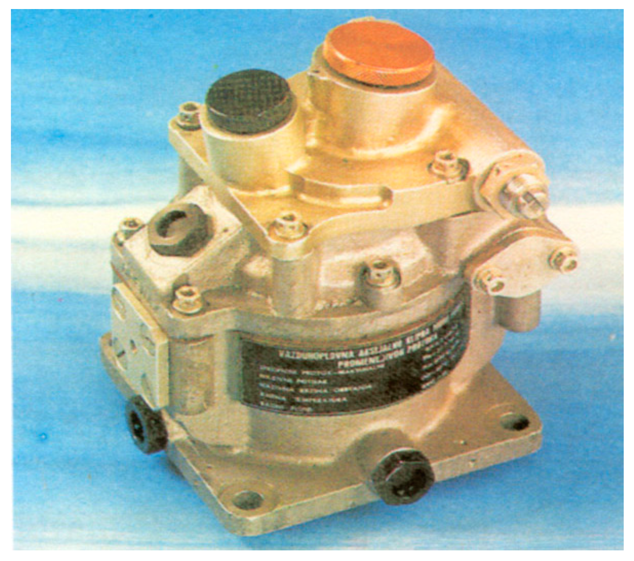
Piston axial pumps with constant pressure (Figure 1) belong to the group of pumps with automatic regulation of the flow depending on the pressure, which changes within the limits set in advance [20].
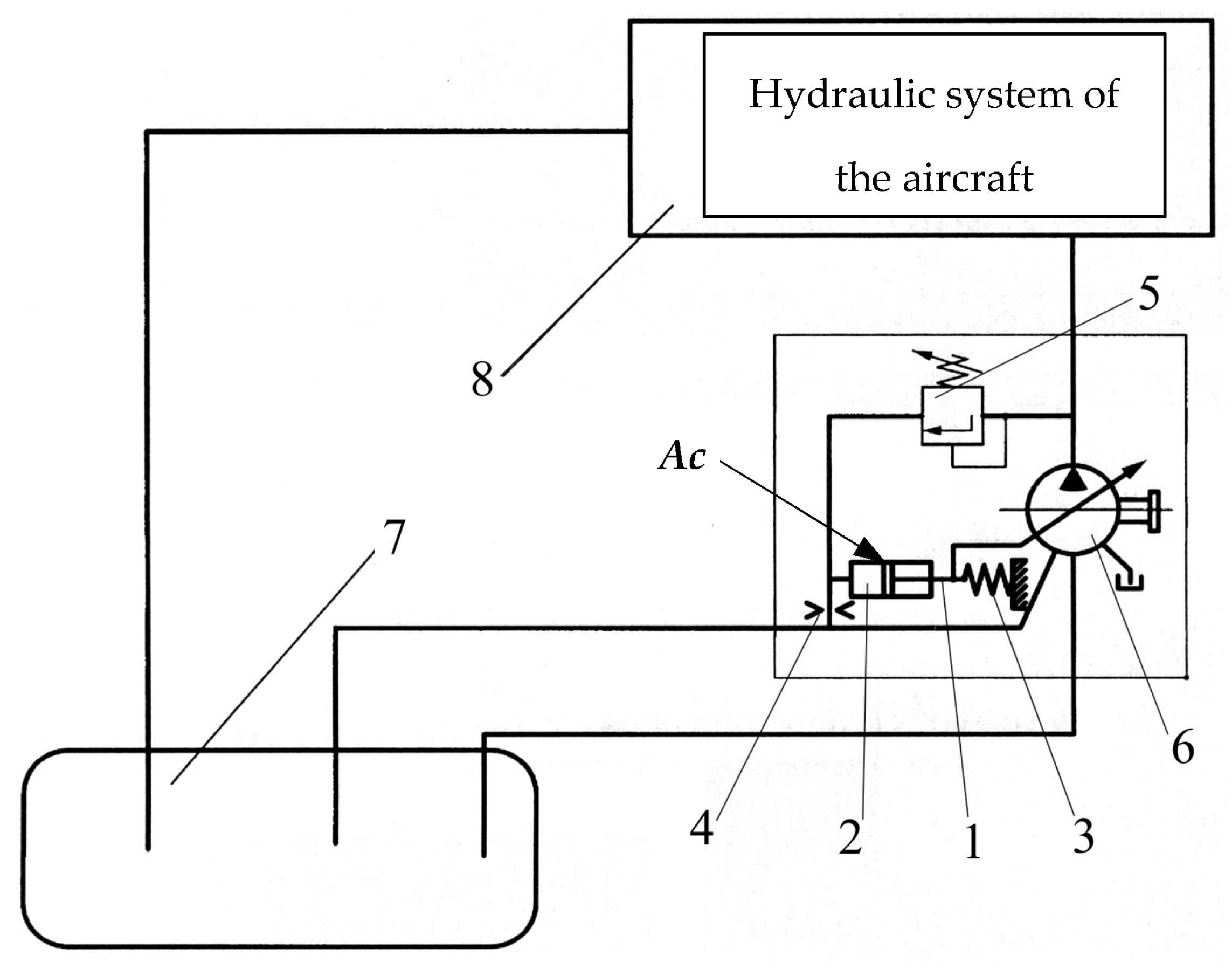
The principle of regulating the operation of the pump is given in Figure 2. The flow of fluid through the regulating distributor (pos. 5) depends on the pressure that opens the distributor [21]. The fluid flow is given by the input characteristic through the choke (pos. 4), which depends on the opening and fluid pressure in the cylinder (pos. 2).
On the one hand, a force acts on the swash plate, the intensity of which depends on the pressure and the area of the piston, Ac. On the other hand, the spring force acts on the swash plate, the intensity of which depends on the stiffness of the spring and the length by which the spring is compressed. The piston rod (pos. 1) changes the angle of inclination of the swash plate and thus regulates the output flow.
The hydraulic system in an aircraft plays a crucial role in various operations, including controlling flight surfaces, landing gear, brakes and other critical functions. The design of an aircraft’s hydraulic system is carefully engineered to ensure reliability, safety and optimal performance. Operational and structural parameters of the aircraft hydraulic system powered by a piston axial pump with constant pressure and variable flow are shown in Table 1.
Hydraulic pumps are responsible for generating the necessary pressure to move the hydraulic fluid through the system. Engine-driven pumps, electric pumps or air-driven pumps are commonly used for redundancy. Hydraulic pumps are responsible for generating the necessary pressure to move the hydraulic fluid through the system. Engine-driven pumps, electric pumps or air-driven pumps are commonly used for redundancy.
The hydraulic reservoir stores hydraulic fluid and allows for thermal expansion and contraction. It typically includes a fluid level indicator, breather and filter to maintain the cleanliness of the fluid. Filters are used to remove contaminants from the hydraulic fluid, preventing damage to components. Regular maintenance and replacement of filters are essential for system reliability. Accumulators store hydraulic energy and can provide emergency power in case of pump failure. They also help to smooth out pressure fluctuations in the system. Check valves permit fluid flow in one direction only, preventing backflow and maintaining system pressure. They are crucial for preventing unintended movements of hydraulic actuators. Pressure relief valves prevent system overpressure by diverting excess fluid back to the reservoir. They ensure that components and lines are not subjected to pressure beyond their design limits.
Aircraft hydraulic systems include sensors and indicators to monitor fluid levels, pressure and system health. Automated control systems may adjust hydraulic pressures based on flight conditions. Critical components often have redundancy to enhance safety. Emergency procedures are in place to handle hydraulic system failures.
The hydraulic system is integrated into the overall avionics and control systems of the aircraft to ensure seamless operation.
4. Experimental Tests of Static Characteristics and Dynamic Behavior of CPAP
Experimental tests of static characteristics and dynamic behavior of pumps are essential for understanding their performance, efficiency and reliability in various operating conditions. These tests involve measuring and analyzing the pump’s behavior under different parameters.
The pressure generated by the pump at different flow rates under stationary conditions was measured. The efficiency of the pump was determined by measuring the input and output power at different operating points. The pump discharge pressure at different flow rates was measured. Sudden changes in flow rate and pressure were simulated to observe pump response. The time required for the pump to reach a steady state after a disturbance was measured. The pump was subjected to input signals of different frequencies and amplitudes. How the pump responded to different frequencies was analyzed to identify resonant frequencies and potential instabilities.
The sudden closing and opening of the valve were simulated to evaluate the response of the pump to transient pressure changes. Pressure peaks were measured, and the pump’s ability to cope with the effects of hydraulic shocks was observed. We reduced the pressure at the pump suction to cause cavitation and used accelerometers and vibration sensors to analyze vibrations in the pump. Vibration frequencies and amplitudes were analyzed to identify potential mechanical problems. The temperature of the critical components of the pump during continuous operation was observed. An assessment was made of the pump’s ability to dissipate heat and avoid an excessive temperature rise.
After a longer period of operation, an inspection of the pump components and an assessment of their wear and tear during operation was carried out. An assessment of the durability and performance of the pump over time was performed. Pump efficiency was tested at different operating speeds to understand the speed-dependent performance.
Pressure transducers, flow meters, temperature sensors and vibration sensors were used for accurate data collection. A robust data acquisition system was used to capture and analyze data in real time. Safety protocols were implemented to prevent accidents during testing, especially in high-pressure environments.
Test equipment and instruments are certified for accurate and reliable results. By systematically conducting static and dynamic tests, engineers can gain a comprehensive understanding of a pump’s performance characteristics, identify potential problems and optimize its design for efficiency and reliability.
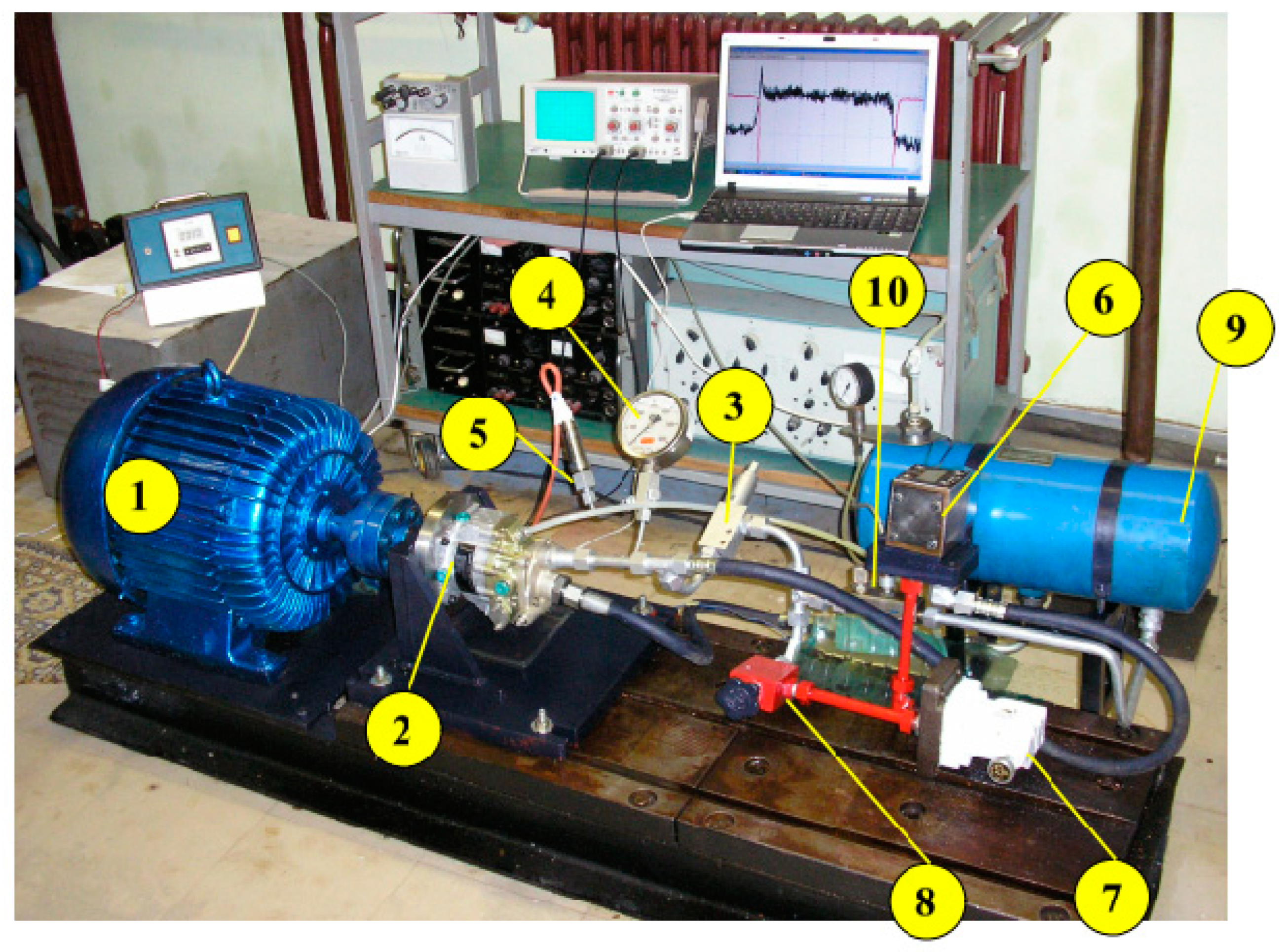
For experimental research on the static and dynamic characteristics of the CPAP, a hydraulic system was installed in the Laboratory for Hydraulics and Pneumatics “PPT-Namenska” Trstenik, which is shown in Figure 3. The experimental hydraulic system is similar to the real hydraulic system of the “Orao” aircraft [22,23,24]. During the experiment, the pump is driven by an electric motor. In the aircraft hydraulic system, the pump is driven by a gear reducer shaft from an airplane jet engine.
In addition, the laboratory hydraulic system contains far fewer components than the hydraulic system of the aforementioned aircraft. The pump works in a pressurized system with volume regulation in laboratory conditions. Energy losses are small, and the working fluid heats a little [25,26].
A pneumatic aggregate is connected to the hydraulic system, which has the task of maintaining a certain overpressure in the hydraulic reservoir. The pressure in the tank is constantly maintained within the limits of 0.2 to 0.3 MPa, which is enough for the high-quality operation of the pump. In these conditions, cavitation does not occur even with the fastest flow change processes.
In the tank of the experimental hydraulic system, there is about 7 × 10⁻³ m3 of working fluid, which participates in the transformation and transmission of power, which is approximately 7.4 kW. The experimental hydraulic system contains mineral-based hydraulic fluid, Hidraol 15, with a kinematic viscosity of ν = 15 × 10−6 m2/s at a temperature of 40 °C. The applied Hidraol 15 is similar in characteristics to the hydraulic working fluid used in aircraft systems. The pump under test is designed to work with “Aero Shell 40” oil, which is used for the temperature range from −55 °C to 135 °C.
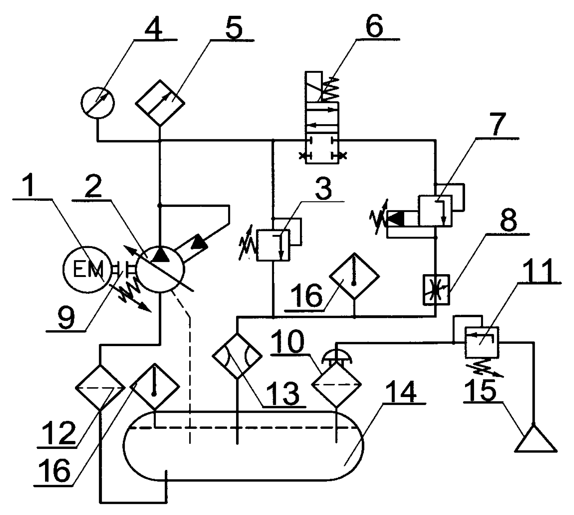
In times when the system does not need hydrostatic energy, the pump reduces the flow to approx. m3/s. Then, it absorbs far less power than when excess fluid is returned to the tank after pressure reduction. In the hydraulic system (Figure 4), there is an electromagnetic distributor (pos. 6) with which the flow of the pump can be translated very quickly from the maximum to the minimum value. There is a safety valve in the pressure line (pos. 3), which, if necessary, relieves the system to the set level. The indirect action pressure regulator (pos. 7) enables precise pressure regulation in the pressure line, while small pressure variations are regulated by means of a variable resistance damper (pos. 8).
Four parameters were included in the experimental tests:
- Pressure in the discharge line;
- Pump flow;
- Temperature of the working fluid in the tank;
- Temperature at the outlet of the variable resistance choke.
4.1. Changes in Pump Flow When the Pressure Changes from the Set Point to the Maximum Set Value
In the hydraulic system of the aircraft, the pressures change from the minimum value pmin is dictated by the actuators with their resistances, through the nominal value, pn, to the maximum value pmax. Then, the flow changes from the nominal value, Qn, to the minimum value, Qmin.
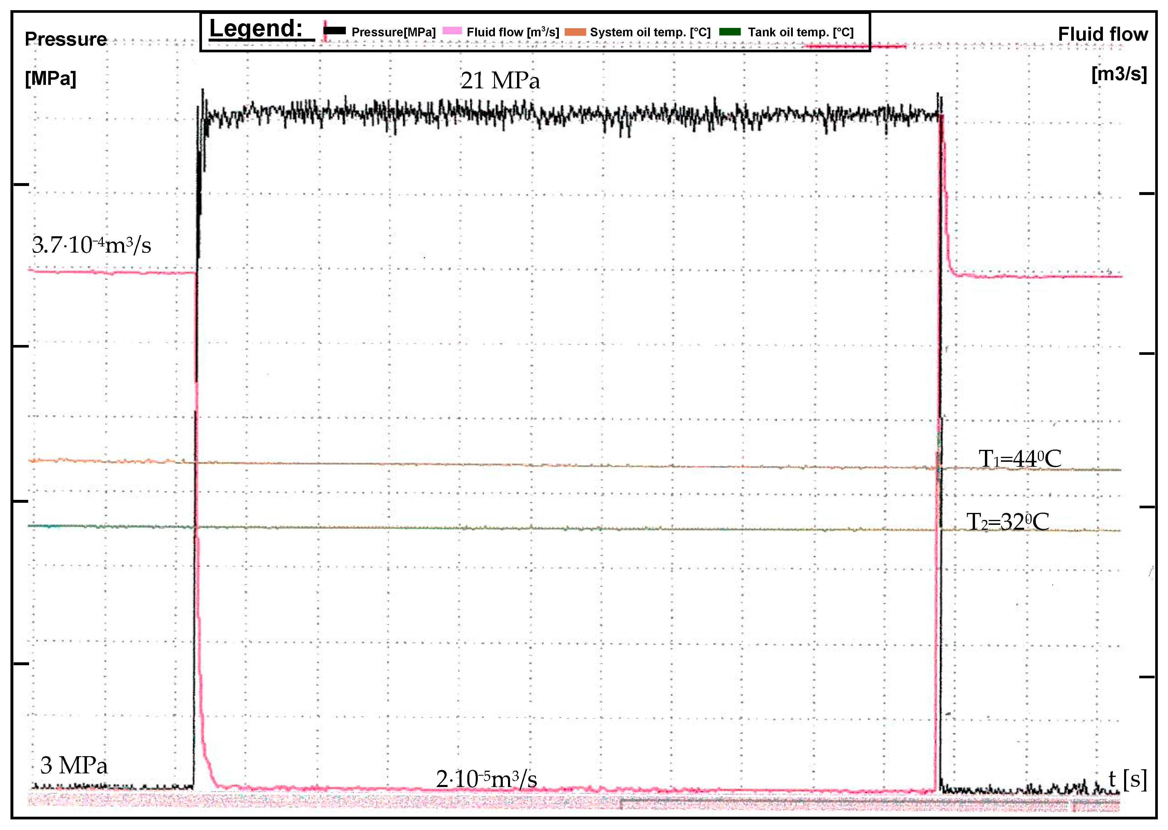
The experiment was carried out in such a way that the working pressure was set to pr = 3 MPa, and then by instantly closing the electromagnetic distributor (pos. 6) (Figure 4), which was in the flow position, the pressure increased to the level of the set pressure interval of pn = 20 MPa up to pmax = 21 MPa. After a certain time, the electromagnetic distributor was opened again, and thus, the characteristic of the pump for the given operating mode was obtained. The recorded characteristic of the pump shows that within the set pressure interval, from pn = 20 MPa to pmax = 21 MPa, the flow varies within the limits of Qn to Qmin (Figure 5). In the diagram, two transition modes can be observed at the jump signal of closing and opening of the pressure line.
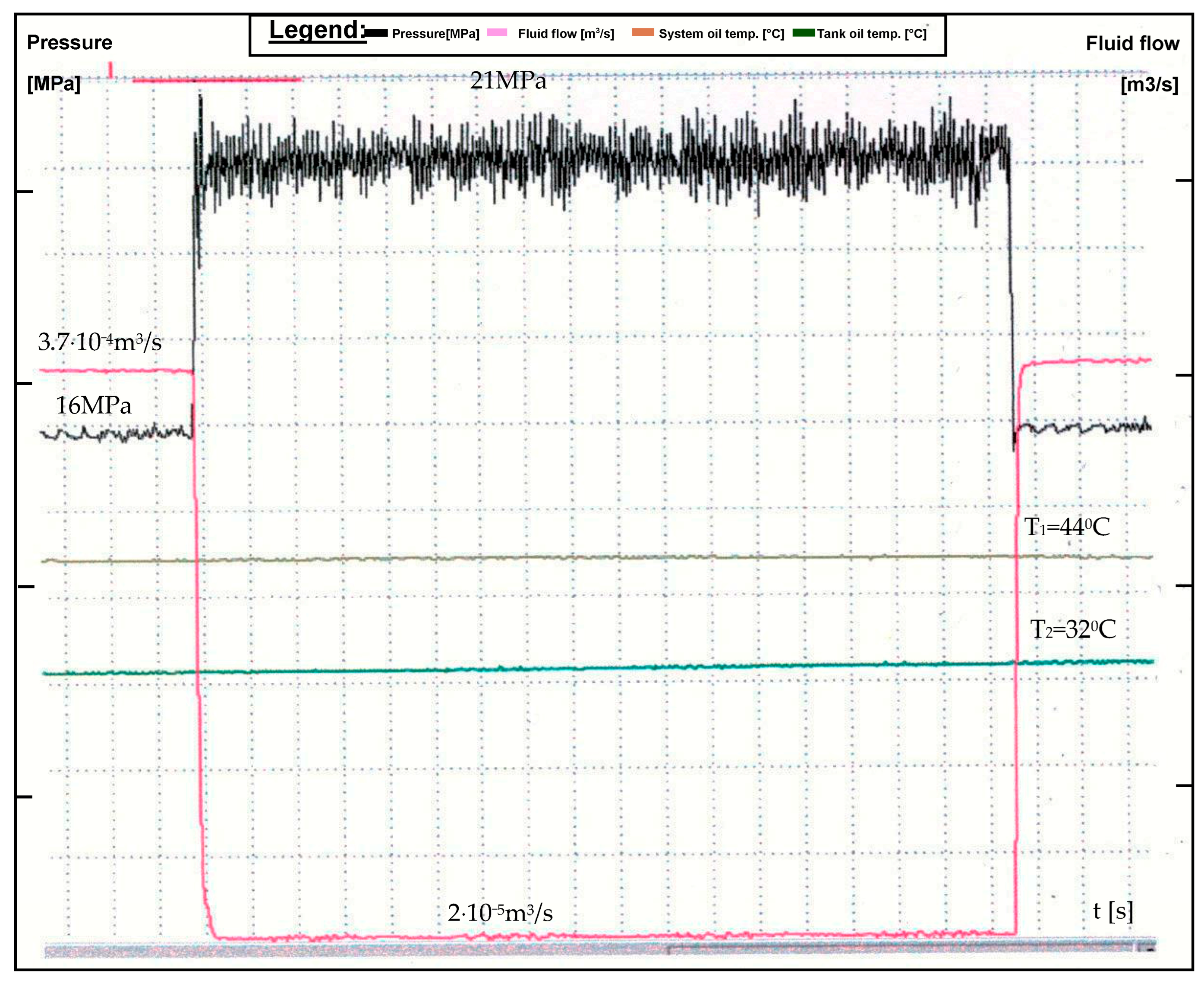
When using the pressure regulator (pos. 7), the working pressure is set to the value pr = 16 MPa. By activating the electromagnetic distributor (pos. 6), the pressure increases to pmax = 21 MPa, and the pump flow changes within the limits of Qn to Qmin (Figure 6).
It can be seen that changes in flow and pressure are strictly dependent and that a change in one quantity causes a precise and rapid change in the other quantity, regardless of the starting pressure level.
4.2. Changes in Pump Flow when Changing Two Maximum Pressure Values
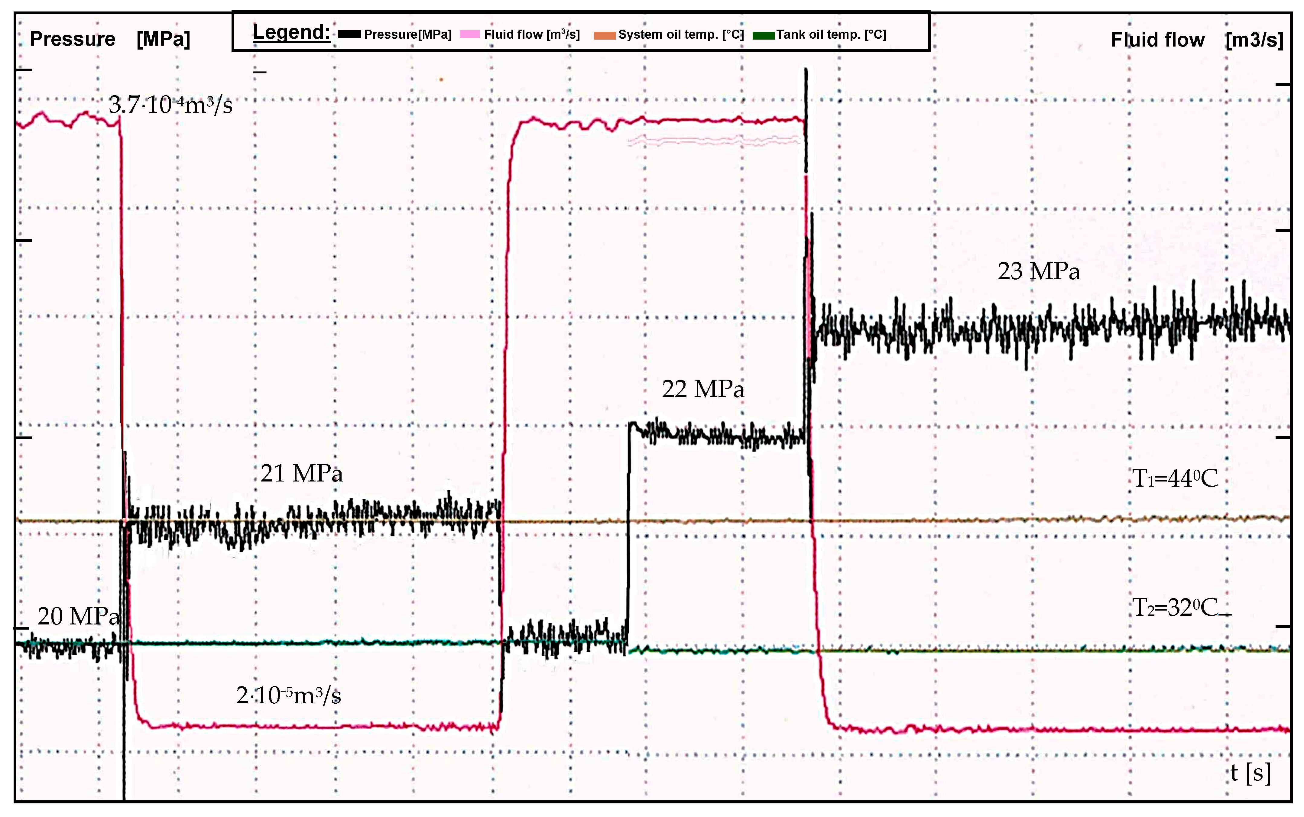
In order to check the stability of the pump operation with an increased maximum pressure, a new characteristic of the pump was recorded. By adjusting the HPT, the maximum pressure was increased to the value pmax = 23 MPa. The change in maximum pressure was performed by changing the preload of the HPT spring, which caused an increase in the maximum pressure, and the nominal pressure was set to pn = 22 MPa. All other parameters are as in Section 3, and the recorded characteristic is shown in Figure 7. The diagram also shows the usual operating mode when the pump works with nominal pressure pn = 20 MPa and maximum pressure pmax = 21 MPa. It is obvious that the pump works stably even with a different maximum pressure, without a large pulsation of pressure and flow, excluding certain noises in the electronic system that occur when recording the diagram.
5. Conclusions
The paper analyzed the performance of the pump with theoretical expectations and industrial standards. The efficiency of the pump in different operating conditions was analyzed. An assessment of the performance of the axial piston pump in terms of constant pressure and variable flow was performed. The reliability of the pump was evaluated based on the experimental results. An analysis of the wear of the parts observed during the test period was performed. Energy consumption was analyzed in all potential efficiency improvements. Areas for further research and development have been identified.
The methods of testing and presenting the basic performance in the stationary state according to the international standard ISO 4409:2019 were used [27]. The specified methods for measuring the performance characteristics of hydraulic components are covered by the ISO 10767-1:2015 standard [28].
The paper carried out a detailed analysis of the hydraulic system requirements, including pressure and flow requirements at different points.
The specific needs of the aircraft hydraulic system are essential for proper pump selection and optimization. The choice of the test stand and the appropriate pump size was made based on the pressure and flow of the system. Factors such as the number of actuators, the size of the hydraulic lines and the overall layout of the hydraulic system were taken into account. For the experiment, a reciprocating axial pump with the possibility of variable displacement was selected. This allows the pump to adjust its power according to the different demands of the hydraulic system, improving efficiency and reducing energy consumption. Pressure control valves are built into the hydraulic system to regulate and maintain constant pressure. These valves ensure system pressure stabilization and prevent excessive fluctuation. Flow control devices are incorporated to manage and distribute the flow within the hydraulic system. This ensures that each component receives the necessary flow rate while maintaining the required constant pressure.
The dynamic response of the pump to rapid changes in load or demand is taken into account. A pump with a fast response time allows the hydraulic system to quickly adapt to different conditions, improving the overall performance of the system. Measures have been implemented to control and manage the temperature within the hydraulic system. The influence of heat on the viscosity of the hydraulic fluid and, consequently, on the efficiency of the pump was analyzed.
The constant pressure piston axial pump belongs to the group of complex components of the hydraulic system of the aircraft, in the internal structure of which numerous and complex interactions take place. The aforementioned circumstances impose the need and justify the obligation to constantly improve the characteristics in order to increase the performance of the complete hydraulic system on the plane. It was found that hydro systems on aircraft are very complex, with a large number of very strict requirements that are placed on hydro pumps, which are generators of hydrostatic energy in the systems. Analyses have shown that piston axial pumps with constant pressure and variable volume, which work in two modes, are the most suitable. Thus, depending on the pressure feedback, the pump operates in constant flow or constant pressure mode. It was also concluded that hydraulic pumps with a folding plate have an advantage in application because they have a small inertial mass of the parts that participate in the process of switching the pump from one mode of operation to another and vice versa. Due to these facts, vane pumps have a lower time constant, which is a very important characteristic of aircraft hydraulic systems.
Author Contributions
Conceptualization, R.P. and A.B.; methodology, R.P. and A.B.; software, A.B. and R.P.; validation, A.B. and R.P.; formal analysis, A.B. and R.P.; investigation, A.B. and R.P.; resources, A.B. and R.P.; data curation, A.B. and R.P.; writing—original draft preparation, R.P., A.B., M.A., H.R.Q. and K.A.A.; writing—review and editing, R.P., A.B., M.A., H.R.Q. and K.A.A.; visualization, A.B.; supervision, R.P.; funding acquisition, R.P. All authors have read and agreed to the published version of the manuscript.
Funding
This paper is funded by the University “Union-NikolaTesla”, Faculty of Information Technology and Engineering.
Institutional Review Board Statement
Not applicable.
Informed Consent Statement
Not applicable.
Data Availability Statement
Data are contained within the article.
Acknowledgments
The authors would like to thank the Editor-in-Chief, Editor and anonymous reviewers for their valuable reviews.
Conflicts of Interest
The authors declare no conflict of interest.
References
- Khan, K.; Sohaib, M.; Rashid, A.; Ali, S.; Akbar, H.; Basit, A.; Ahmad, T. Recent trends and challenges in predictive maintenance of aircraft’s engine and hydraulic system. J. Braz. Soc. Mech. Sci. Eng. 2021, 43, 403. [Google Scholar] [CrossRef]
- Guo, S.; Chen, J.; Lu, Y.; Wang, Y.; Dong, H. Hydraulic piston pump in civil aircraft: Current status, future directions and critical technologies. Chin. J. Aeronaut. 2020, 33, 16–30. [Google Scholar] [CrossRef]
- Ma, Z.; Wang, S.; Shi, J.; Li, T.; Wang, X. Fault diagnosis of an intelligent hydraulic pump based on a nonlinear unknown input observer. Chin. J. Aeronaut. 2018, 31, 385–394. [Google Scholar] [CrossRef]
- Banaszek, A.; Petrovic, R.; Andjelkovic, M.; Radosavljevic, M. Conceptof Efficiency of a Twin-Two-Pump Hydraulic Power Pack with Pumps Equipped in Constant Pressure Regulators with Different Linear Performance Characteristics. Energies 2022, 15, 8100. [Google Scholar] [CrossRef]
- Todić, N.; Savić, S.; Gordić, D.; Petrović, R. Experimental Research of the Hydrodynamic Processes of an Axial Piston Water Hydraulic Pump. Machines 2022, 10, 728. [Google Scholar] [CrossRef]
- Lyu, F.; Zhang, J.; Zhao, S.; Li, K.; Xu, B.; Huang, W.; Xu, H.; Huang, X. Coupled evolution of piston asperity and cylinder bore contour of piston/cylinder pair in axial piston pump. Chin. J. Aeronaut. 2023, 36, 395–407. [Google Scholar] [CrossRef]
- Zhou, J.; Zhou, J.; Jing, C. Experimental Research on the Dynamic Lubricating Performance of Slipper/Swash Plate Interface in Axial Piston Pumps. Chin. J. Mech. Eng. 2020, 33, 25. [Google Scholar] [CrossRef]
- Wang, S. Generic Modeling and Control of an Open-Circuit Piston Pump—Part I: Theoretical Model and Analysis. J. Dyn. Syst. Meas. Control 2016, 138, 041004. [Google Scholar] [CrossRef]
- Wang, S. Generic Modeling and Control of an Open-Circuit Piston Pump—Part II: Control Strategies and Designs. J. Dyn. Syst. Meas. Control 2016, 138, 041005. [Google Scholar] [CrossRef]
- Ouyang, X.-P.; Li, L.; Fang, X.; Yang, H.-Y. Dynamic characteristics of dual-pressure switch for aircraft piston pump. J. Zhejiang Univ. Eng. Sci. 2016, 50, 397–404. [Google Scholar]
- Chao, Q.; Zhang, J.; Xu, B.; Wang, Q. Discussion on the Reynolds equation for the slipper bearing modeling in axial piston pumps. Tribol. Int. 2018, 118, 140–147. [Google Scholar] [CrossRef]
- Banaszek, A.; Petrovic, R. Problem of Non Proportional Flow of Hydraulic Pumps Working with Constant Pressure Regulators in Big Power Multipump Power Pack Unit in Open System. Tech. Gaz. 2019, 2, 294–301. [Google Scholar]
- Karpenko, M.; Bogdevcius, M. Investigation into the hydrodynamic processes of fitting connections for determining pressure losses of transport. Transport 2020, 35, 108–120. [Google Scholar] [CrossRef]
- Guo, R.; Zhao, Z.; Huo, S.; Jin, Z.; Zhao, J.; Gao, D. Research on State Recognition and Failure Prediction of Axial Piston Pump Based on Performance Degradation Data. Processes 2020, 8, 609. [Google Scholar] [CrossRef]
- Huang, B.; Wang, S.; Meng, Y.; Shi, J. Energy-saving optimization for intelligent pumps based on performance reliability restriction. J. Beihang Univ. 2013, 4, 559–563. [Google Scholar]
- Fiebing, C.; Xiujuan, L.; Smolka, S. Pressure compensator (PC) pressure overshoot analysis and experimental research of an open circuit pump. In Proceedings of the IEEE 2015 International Conference on Fluid Power and Mechatronics (FPM), Harbin, China, 5–7 August 2015; pp. 910–913. [Google Scholar]
- Achten, P. Dynamic high-frequency behaviour of the swash plate in a variable displacement axial piston pump. Proc. Inst. Mech. Eng. Part I J. Syst. Control Eng. 2013, 227, 529–540. [Google Scholar] [CrossRef]
- Mandal, N.P.; Saha, R.; Mookherjee, S.; Sanyal, D. Pressure compensator design for a swash plate axial piston pump. J. Dyn. Syst. Meas. Control 2014, 136, 021001. [Google Scholar] [CrossRef]
- Kemmetmüller, W.; Fuchshumer, F.; Kugi, A. Nonlinear pressure control of self-supplied variable displacement axial piston pumps. Control Eng. Pract. 2010, 18, 84–93. [Google Scholar] [CrossRef]
- Wang, S.P.; Tomovic, M.; Liu, H. Commercial Aircraft Hydraulic System; Shanghai Jiao Tong University Press: Shanghai, China, 2015; pp. 186–190. [Google Scholar]
- Patrosz, P. Influence of Properties of Hydraulic Fluid on Pressure Peaks in Axial Piston Pumps’ Chambers. Energies 2021, 14, 3764. [Google Scholar] [CrossRef]
- Koivumäki, J.; Mattila, J. Adaptive and nonlinear control of discharge pressure for variable displacement axial piston pumps. J. Dyn. Syst. Meas. Control 2017, 139, 101008. [Google Scholar] [CrossRef]
- Wei, J.; Guo, K.; Fang, J.; Tian, Q. Nonlinear supply pressure control for a variable displacement axial piston pump. Proc. Inst. Mech. Eng. Part I J. Syst. Control Eng. 2015, 229, 614–624. [Google Scholar] [CrossRef]
- Axin, M.; Eriksson, B.; Krus, P. A Hybrid of Pressure and Flow Control in Mobile Hydraulic Systems. In Proceedings of the 9th International Fluid Power Conference (IFK), Aachen, Germany, 24–26 March 2014; Volume 1, pp. 190–201. [Google Scholar]
- Xu, M.; Jin, B.; Chen, G.; Ni, J. Speed-Control of Energy Regulation based Variable-Speed Electrohydraulic Drive. J. Mech. Eng. 2013, 59, 433–442. [Google Scholar] [CrossRef]
- Pančík, J.; Maxera, P. Control of Hydraulic Pulse System Based on the PLC and State Machine Programming. Designs 2018, 2, 48. [Google Scholar] [CrossRef]
- Standard ISO 4409:2019; Hydraulic Fluid Power—Positive Displacement Pumps, Motors and Integral Transmissions—Methods of Testing and Presenting Basic Steady State Performance. ISO: Geneva, Switzerland, 2019.
- Standard ISO 10767-1:2015; Hydraulic Fluid Power—Determination of Pressure Ripple Levels Generated in Systems and Components—Part 1: Method for Determining Source Flow Ripple and Source Impedance of Pumps. ISO: Geneva, Switzerland, 2015.
Figure 1.
Piston axial constant pressure pump.

Figure 2.
Functional diagram of a constant pressure pump. 1—piston rod; 2—cylinder; 3—spring; 4—muffler; 5—distributor for regulation; 6—hydraulic pump; 7—pressure tank; 8—actuators of working fluid.
Figure 2.
Functional diagram of a constant pressure pump. 1—piston rod; 2—cylinder; 3—spring; 4—muffler; 5—distributor for regulation; 6—hydraulic pump; 7—pressure tank; 8—actuators of working fluid.

Figure 3.
The laboratory hydraulic system for testing CPAP. 1—electric motor; 2—hydraulic pump; 3—safety valve; 4—manometer; 5—pressure transducer; 6—electromagnetic distributor; 7—pressure regulator; 8—muffler; 9—flow converter; 10—pressure tank.
Figure 3.
The laboratory hydraulic system for testing CPAP. 1—electric motor; 2—hydraulic pump; 3—safety valve; 4—manometer; 5—pressure transducer; 6—electromagnetic distributor; 7—pressure regulator; 8—muffler; 9—flow converter; 10—pressure tank.

Figure 4.
Scheme of the laboratory hydraulic system for testing CPAP. 1—electric motor; 2—pump CPAP; 3—safety valve; 4—manometer; 5—pressure transducer; 6—electromagnetic distributor; 7—pressure regulator of indirect action; 8—damper of variable resistance; 9—elastic coupling; 10—intake filter; 11—air pressure regulator; 12—intake filter; 13—flow converter; 14—pressure tank; 15—pressure air source; 16—temperature converter.

Figure 5.
Diagram of the change in flow when the pressure changes from pr = 3 MPa to pmax = 21 MPa (pressure range from 3 to 23 MPa, the cut-off value is 2 MPa).
Figure 5.
Diagram of the change in flow when the pressure changes from pr = 3 MPa to pmax = 21 MPa (pressure range from 3 to 23 MPa, the cut-off value is 2 MPa).

Figure 6.
Diagram of the flow rate change when the pressure changes from pr = 16 MPa to pmax = 21 MPa (pressure range 6 to 23 MPa; the value of the partition is 1.7 MPa).
Figure 6.
Diagram of the flow rate change when the pressure changes from pr = 16 MPa to pmax = 21 MPa (pressure range 6 to 23 MPa; the value of the partition is 1.7 MPa).

Figure 7.
Diagram of the change in flow when the pressure changes in two levels, from 20 MPa to 21 MPa and from 22 MPa to 23 MPa (the pressure range is from 13 to 23 MPa; the value of the division on the diagram is 1 MPa).
Figure 7.
Diagram of the change in flow when the pressure changes in two levels, from 20 MPa to 21 MPa and from 22 MPa to 23 MPa (the pressure range is from 13 to 23 MPa; the value of the division on the diagram is 1 MPa).


Table 1.
Operational and structural parameters of the aircraft hydraulic system powered by a piston axial pump with constant pressure and variable flow.
Table 1.
Operational and structural parameters of the aircraft hydraulic system powered by a piston axial pump with constant pressure and variable flow.
| Title | Value | |
|---|---|---|
| ε1 | HPT spring preload | ε1 = 1.4 × 10⁻³ m |
| c1 | HPT spring stiffness | c1 = 5.5 × 10⁴ N/m |
| m1 | piston mass HPT | m1 = 3 × 10⁻³ kg |
| ft1 | piston viscous friction force HPT | ft1 = 70 Ns/m |
| K1 | HPT flow amplification coefficient | K1 = 0.170 m2/s |
| Av | piston surface HPT | Av = 8 × 10⁻⁶ m2 |
| K2 | flow loss coefficient at HC | K2 = 2 × 10⁻¹² m5/Ns |
| K3 | flow coefficient due to compressibility | K3 = 4 × 10¹⁵ N/m5 |
| Ac | piston surface HC | Ac = 1.26 × 10⁻⁴ m2 |
| ε2 | spring bias HC | ε2 = 9 × 10⁻³ m |
| c2 | spring stiffness HC | c2 = 2 × 10⁴ N/m |
| ft2 | force of viscous friction of the piston HC | ft2 = 100 Ns/m |
| B | compressibility modulus of the fluid | B = 1.4 × 10¹⁵ N/m2 |
| m2 | piston mass HC | m2 = 8.52 × 10⁻¹ kg |
| K4 | the coefficient of change of the angle of the swash plate | K4 = 27.5 rad/m |
| K5 | HC flow gain coefficient | K5 = 1.14 × 10⁻³ m3/s rad |
| K6 | coefficient of total leakage of the pump | K6 = 4 × 10⁻¹³ m3/Ns |
| K7 | compressibility coefficient of the entire container | K7 = 9.33 × 10¹⁴ m5/N |
| n | pump shaft rotation frequency [9] | n = 1500 r/min |
| q | specific pump flow | q = 15 × 10−6 m3/r |
| γmax | maximum angle of the swash plate | γmax = 19° = 0.33 rad |
| Qn | nominal flow rate of the pump | Qn = 3.7 × 10⁻⁴ m3/s |
| pn | nominal pressure of the pump | pn = 200 × 105 Pa |
| pmax | maximum pump pressure | pmax = 211 × 105 Pa |
| Δγ | swash plate sensitivity threshold | Δγ = 1 × 10⁻³ rad |
Disclaimer/Publisher’s Note: The statements, opinions and data contained in all publications are solely those of the individual author(s) and contributor(s) and not of MDPI and/or the editor(s). MDPI and/or the editor(s) disclaim responsibility for any injury to people or property resulting from any ideas, methods, instructions or products referred to in the content. |
© 2023 by the authors. Licensee MDPI, Basel, Switzerland. This article is an open access article distributed under the terms and conditions of the Creative Commons Attribution (CC BY) license (https://creativecommons.org/licenses/by/4.0/).
Share and Cite
MDPI and ACS Style
Petrović, R.; Banaszek, A.; Andjelković, M.; Qananah, H.R.; Alnagasa, K.A. Experimental Tests of the Piston Axial Pump with Constant Pressure and Variable Flow. Designs 2024, 8, 5. https://doi.org/10.3390/designs8010005
AMA Style
Petrović R, Banaszek A, Andjelković M, Qananah HR, Alnagasa KA. Experimental Tests of the Piston Axial Pump with Constant Pressure and Variable Flow. Designs. 2024; 8(1):5. https://doi.org/10.3390/designs8010005
Chicago/Turabian StylePetrović, Radovan, Andrzej Banaszek, Maja Andjelković, Hana R. Qananah, and Khalefa A. Alnagasa. 2024. "Experimental Tests of the Piston Axial Pump with Constant Pressure and Variable Flow" Designs 8, no. 1: 5. https://doi.org/10.3390/designs8010005