1. Introduction and Literature Review
Currently, vehicular traffic is increasingly growing and becoming more demanding of the integrity of transport infrastructures and their components than ever. In this context, Structural Health Monitoring (SHM) of these critical civil engineering assets has become ever more a priority for administrations and stakeholders around the world, as it stands as a crucial activity for preventing negative impacts on the structural stability and operational safety of transport infrastructures. To achieve such an objective, it is necessary to develop a viable methodology to optimize the process of monitoring, data acquisition, storage and subsequent maintenance activities.
Non-Destructive Testing methods (NDTs) have gained momentum in the last decade as cost-effective infrastructure monitoring tools, since they have been successfully applied to achieve extensive and efficient assessments without compromising the civil infrastructures’ structural integrity [
1,
2]. Among these techniques, Mobile Laser Scanner (MLS) and Ground-Penetrating Radar (GPR) applications throughout the civil engineering field have been thoroughly analyzed, in order to study the implementation of their information in transport infrastructures management processes. GPR has been used in different instances to collect useful data for multiple assets of civil engineering works [
3]. Moreover, its use in pavement monitoring has been tested and carried out in numerous occasions, proving its effectiveness in detecting possible damages and the conditions of the inspected infrastructures [
4]. Furthermore, the combined use of GPR with other NDTs can provide a more accurate insight into the infrastructure condition and the possible maintenance necessities that it might present [
5,
6,
7,
8]. Indeed, these NDT surveys are usually conducted separately by different operators, and the outputs that they provide are generally analyzed independently from one another. Conversely, a unified environment that stores and updates this information over time, while allowing an integrated analysis of both datasets, would be crucial to ensure that the assessments are conducted more efficiently.
Building Information Modeling (BIM) appears to be the best available approach to guarantee that such an objective can be reached. In fact, as a result of a European political movement, the advance of BIM procedures has been firmly supported in the field of civil engineering, by means of national and international legislations and directives [
9]. This is the case of Italy, where specific regulations have been issued by the Ministry of Infrastructure and Transport (MIT), introducing the implementation of BIM-based procedures for the design and construction of new civil infrastructures [
10,
11,
12]. BIM has long been used for managing the design processes of architectural works, and it has found great success in the building’s field [
13,
14]. Road infrastructure can represent more complex systems relative to a building, as issues and interferences between their assets are numerous. The creation of a complex and collaborative digital model is then needed, although many procedures are not yet widespread, especially in the field related to monitoring and maintenance. In this context, BIM-based procedures for transport infrastructure projects and design are being investigated, and different research studies have been developed, describing the advantages that this methodology can bring to this sector of civil engineering [
15,
16,
17,
18]. In particular, this methodology has been studied in the context of life-cycle assessments of infrastructures design as well as its role in achieving sustainability of new civil engineering projects [
19,
20,
21,
22]. Moreover, specific guidelines on risk classification and management, safety assessment and monitoring of existing bridges have been issued in Italy [
11], following the collapse of the “Polcevera Bridge” in Genoa in August 2018, which created 43 victims and had several implications for the economy of the entire country [
23]. These regulations expressly stated that the use of BIM-based management techniques for existing civil infrastructures must be implemented, even if only on an experimental level. These issues confirm how civil engineering and, more specifically, transport asset management are going to develop in the near future, as confirmed by several recent research studies regarding the use of BIM for transport infrastructures monitoring, maintenance and NDT data integration that have been developed in recent years [
24,
25,
26,
27]. Specifically, a series of research has used BIM processes to integrate pavement data obtained through different survey techniques [
28,
29]. Moreover, infrastructure of particular relevance such as airports has also been the subject of studies related to the use of BIM for existing transportation infrastructure [
30,
31].
2. Objectives
This study represented a step towards asset data management through the use of digital informative models. As MLS and GPR surveys are usually conducted by road owners and contractors to analyze the conditions of infrastructures, the aim of the research was to study a viable process to store the results of these inspections in a single environment. This would allow to perform an integrated analysis of the data extracted from these instruments, as they are usually analyzed separately, to allow a better understanding of the conditions of the infrastructure’s pavement. BIM was identified as the more appropriate methodology to achieve such an objective, as its core objective is to create digital models that can contain information regarding the object they represent.
This study aimed at defining a viable process to generate a BIM model of infrastructure, integrating multiple NDT technologies data outputs collected by several sources, to provide a useful tool for planning maintenance activities of the investigated infrastructure and guarantee a more thorough analysis of its condition. Moreover, a three-dimensional digital model of the road’s pavement and its different layers can ensure the inspection of certain elements of the infrastructure that usually cannot be reached by on-site operators. As both MLS and GPR data were implemented into the digital model of the road, potential pavement distresses could be identified in the deep layers of the superstructure and subsequently integrated into the process. This provided a more comprehensive analysis of the pavement’s conditions and an effective tool to store information regarding possible deteriorations that could cause damages which can affect the structural integrity of inspected infrastructure. Such a model could then be updated over time, analyzing the potential development of the identified distresses to determine the most effective and efficient maintenance program. As presented in the previous section of the article, different papers regarding the integration of NDT data in BIM models have been presented in the last years. However, the combined use of MLS and GPR data to define a digital model of a piece of infrastructure’s pavement is a subject that has not been found to be explored enough in the analyzed literature. Moreover, the implementation of data related to possible distresses and deteriorations of pavement’s deep layers into a digital model represented an innovative concept in the monitoring activities related to the transportation infrastructure sector.
3. Methodology
The BIM methodology is based on the generation of digital informative models capable of integrating multi-source and multi-scale information related to the object they represent. Such a tool can be especially useful in civil engineering applications to ensure that data collected during surveys and monitoring activities are managed and properly stored, improving the maintenance and the management activities related to transport infrastructures. Moreover, this process can be applied to any phase of the infrastructure’s life cycle, guaranteeing a continuous system to manage a particular project from its design phase to the construction and subsequent management stages. In this context, BIM procedures can be identified as suitable solutions to store, visualize and process data obtained from on-site surveys of existing civil infrastructures, integrating the analyses of their conditions into a unique environment.
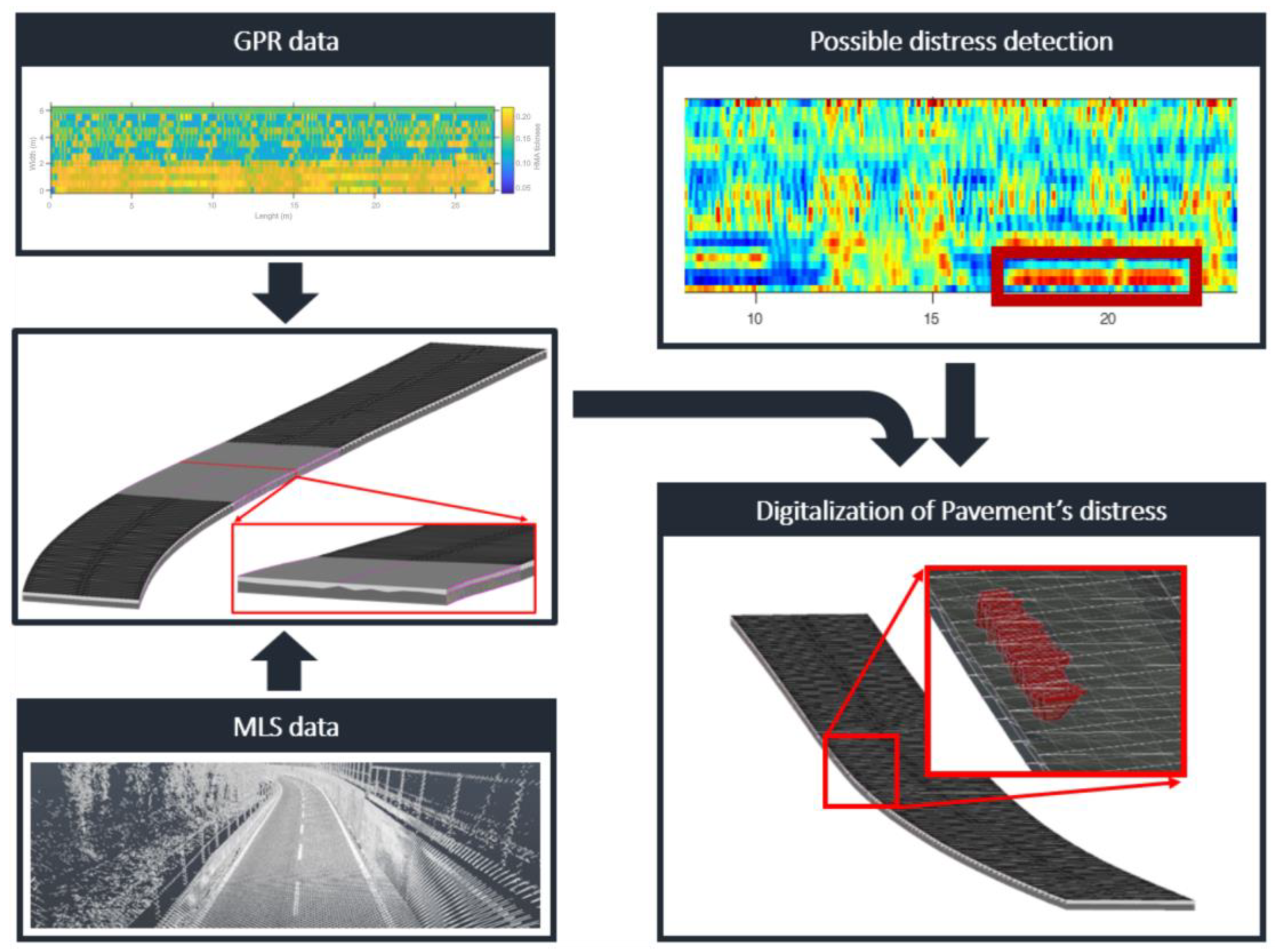
In this study, a process for data integration implementing a BIM model of a road’s pavement is presented. As MLS and GPR surveys were conducted over a piece of infrastructure, the resulting data were processed and used to generate a three-dimensional digital model of the pavement’s superstructure, characterizing the configuration of its deep layers and identifying possible deformations that could result in damages and risks for road users. Moreover, subsequent analyses of the GPR data can detect possible distresses inside the pavement. This information was then included in the digitalization process by generating digital representations of the identified deteriorations that can contain crucial information such as the type of detected distress or the day in which the inspection was conducted.
Figure 1 shows a schematic representation of the process hereby described.
The proposed methodology aimed at defining a process to manage data obtained by on-site surveys. These operations are generally conducted by different operators, and their results are then analyzed separately. Moreover, data storage and management are typically tasks that can present difficulties, and data loss could impact the maintenance phases of a particular infrastructure. By defining a method to store the information obtained from MLS and GPR surveys in a unique digital environment, integrated analyses can be carried out, and data loss can be reduced. Furthermore, even though different pieces of research have been conducted on the integration of NDT data in BIM models, the use of GPR data to define the configuration of a pavement digital model and its possible distresses is still a subject that has not been explored enough in the existing literature.
The proposed process was based on different stages, which will be described in the subsequent paragraphs. After the first phases of on-site survey and data processing, specific digital parametric objects were generated into a BIM environment, capable of adapting their configuration in relation to the information provided by the GPR and MLS inspections. These elements were therefore implemented to define the digital model of the road pavement, thus reconstructing the different layers of the superstructure, as well as the deteriorations detected during the data processing phase. The methodology hereby described could rely on real data, which were obtained during a series of surveys carried out over a stretch of a highway, located near the city of Salerno, in southern Italy. These inspections were performed in the context of the National Project “Extended resilience analysis of transport networks (EXTRA TN): Towards a simultaneously space, aerial and ground sensed infrastructure for risks prevention” (PRIN 2017), which is supported by the Italian Ministry of Education, University and Research.
3.1. Survey Data Management
The first phase of the process presented in this study consisted of the management and processing of NDT survey data. In particular, MLS and GPR inspections were performed, and their outputs were analyzed. By relying on an MLS, an efficient scan of the infrastructure was performed, as the travelling speed of the vehicle did not impede the regular traffic flow over the highway. Moreover, a ground-coupled pulsed GPR system equipped with a multifrequency antenna was employed, requiring the interruption of traffic flow and the temporary closing of the infrastructure.
3.1.1. Ground Penetrating Radar
The widely used geophysical technique known as GPR makes use of data from electromagnetic (EM) field propagation to examine important subsurface features [
32,
33]. The propagation process is controlled by the characteristics of the particular device and the properties of the tested material. In detail, a source internal to the GPR system emits an EM impulse that is partially back-reflected and partially transmitted beyond, at any given dielectric contrast encountered throughout the medium. Imaging of the subsurface features in two and three dimensions is possible thanks to the collection of such diffractive events through a receiving station.
GPR technology was applied for inspecting the selected road stretch. Particularly, the Hi-Mod 200–600 ground-coupled pulsed GPR system manufactured by IDS Georadar S.p.A. was employed. The system is equipped with a multifrequency antenna working at the central frequencies of 200 MHz and 600 MHz.
GPR was able to inspect both shallower and deeper details of the infrastructure’s pavement due to its multiple frequencies and resolutions. A regular grid of scan lines was defined over the road in order to gather an accurate dataset of georeferenced GPR scans. More specifically, the grid’s resolution varied depending on the direction of the scan (i.e., longitudinal, transversal). In particular, for longitudinal and transverse scans, the distance between the two scans was set between 1.0 m and 2.0 m.
The scan direction’s horizontal resolution, namely, the distance between one acquisition and the next, was set to be the same for both directions and equal to 0.05 m. The acquisition parameters are summarized in
Table 1.
The acquired dataset was subject to a typical processing routine in order to maximize the signal-to-noise ratio and to raise the reliability of the interpretation phase:
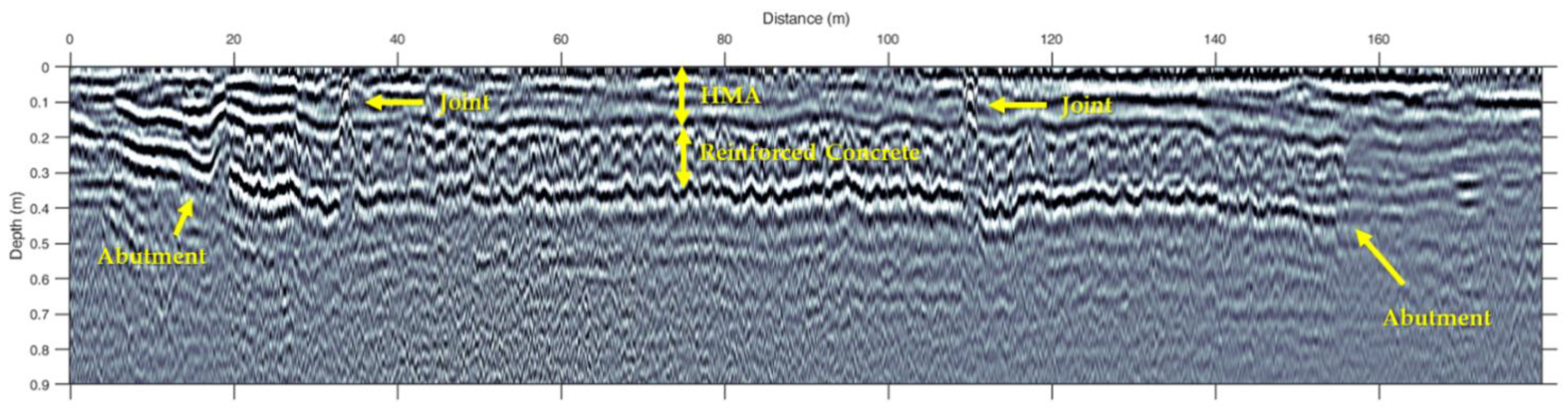
The interpretation of the processed data allowed the detection of key geometric information concerning the configuration of the pavement layers. By observing a GPR Scan collected in longitudinal direction, it is clearly possible to recognize and measure the elements of the bridge included into the analyzed road stretch., as reported in
Figure 2.
The time–depth conversion has been carried out by measuring the EM waves propagation velocity
v by the equation [
33]
, with the dielectric constant e
r being calculated by hyperbola fitting method [
32], which returned values of 6 and 8 for Hot-Mixed Asphalt (HMA) and concrete layers, respectively.
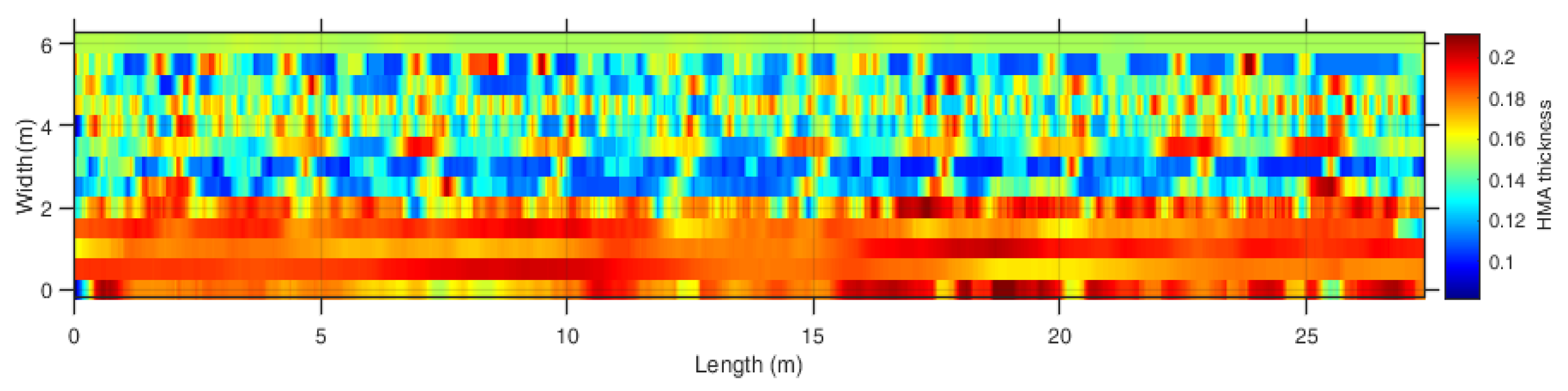
To facilitate the subsequent phases of the study, the results of these inspections were also provided in the form of a matrix containing the HMA layer depth values in respect to the position across the grid. Moreover, through the analysis of the tomographies at progressive depth, it was possible to detect spots of inhomogeneities in reflective behavior, which are likely to be related to distress inner to the pavement. Indeed, as these inspections were carried out over stretches of infrastructure that included a bridge, where delamination, rebar corrosion or branching cracks are observed, it is envisaged a variation of EM response given by the different dielectric contrast between concrete and rebar.
By repeating such an analysis at progressive depth, it was possible to both confirm the distress by checking the spatial coherence of inhomogeneities between different tomographies, and to define a thickness of the pavement interested by the potential decay.
All the acquired information were strategic in supporting the digitalization process of the infrastructure. As an instance,
Figure 3 shows a HMA thickness map obtained by measuring across the inspection area the thickness of the HMA-bond layer.
3.1.2. Mobile Laser Scanner
The second NDT survey was conducted implementing a MLS, a surveying technique that is particularly useful for applications on roads. It makes it possible to collect 3D data from one or more mobile platforms with mounted laser scanners [
34,
35]. When the first mobile systems using LiDAR (light detection and ranging) technology first appeared in the late 20th century, this technique was introduced. Over the past 20 years, it has evolved and become widely used. Given the system’s adaptability and effectiveness, practical applications in the fields of infrastructure engineering have received more attention recently. This technology provides a three-dimensional point cloud, representing the geometrical configuration of the civil infrastructure analyzed. As the laser signal is emitted from the instrument, it is reflected by any object it encounters with different levels of intensity, which can be shown by means of a chromatic scale. By measuring the time between the emission of the signal and its return after the reflection, the distance between the analyzed object and the instrument can be determined.
The mobile laser scanner (Road-SIT Survey, created by Siteco Informatica s.r.l.) mounted on the roof of a car traveling along a motorway collected the data. Two Faro CAM2 Focus laser scanners were mounted symmetrically on the left and right sides of the measuring head, pointing around 45 degrees toward the back of the vehicle (‘X’ pattern). The mirror speed of the laser was 96 Hz, and its acquisition frequency was 976 kHz. As the vehicle traveled at 90 km/h along the analyzed stretch of a highway, a resulting point cloud with a density of around 4000 points for m2 was obtained. The resulting scan lines had an angular range of 320° and a distance range of 80 m, and the distance between scanning lines was approximately 11 cm.
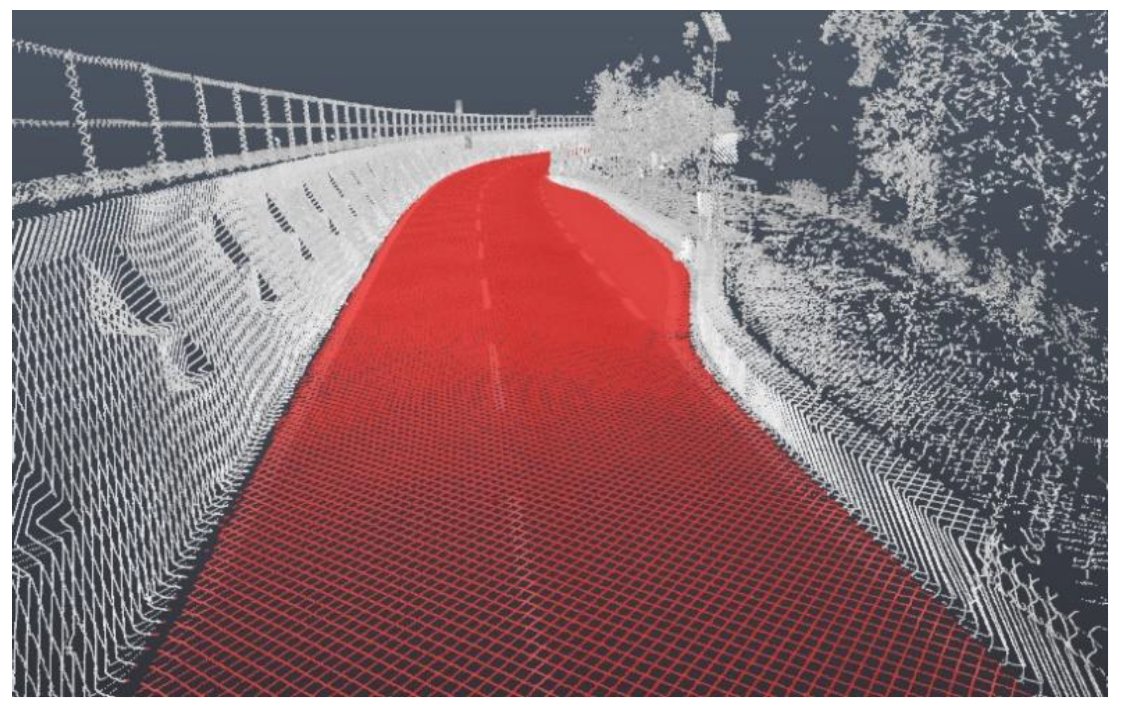
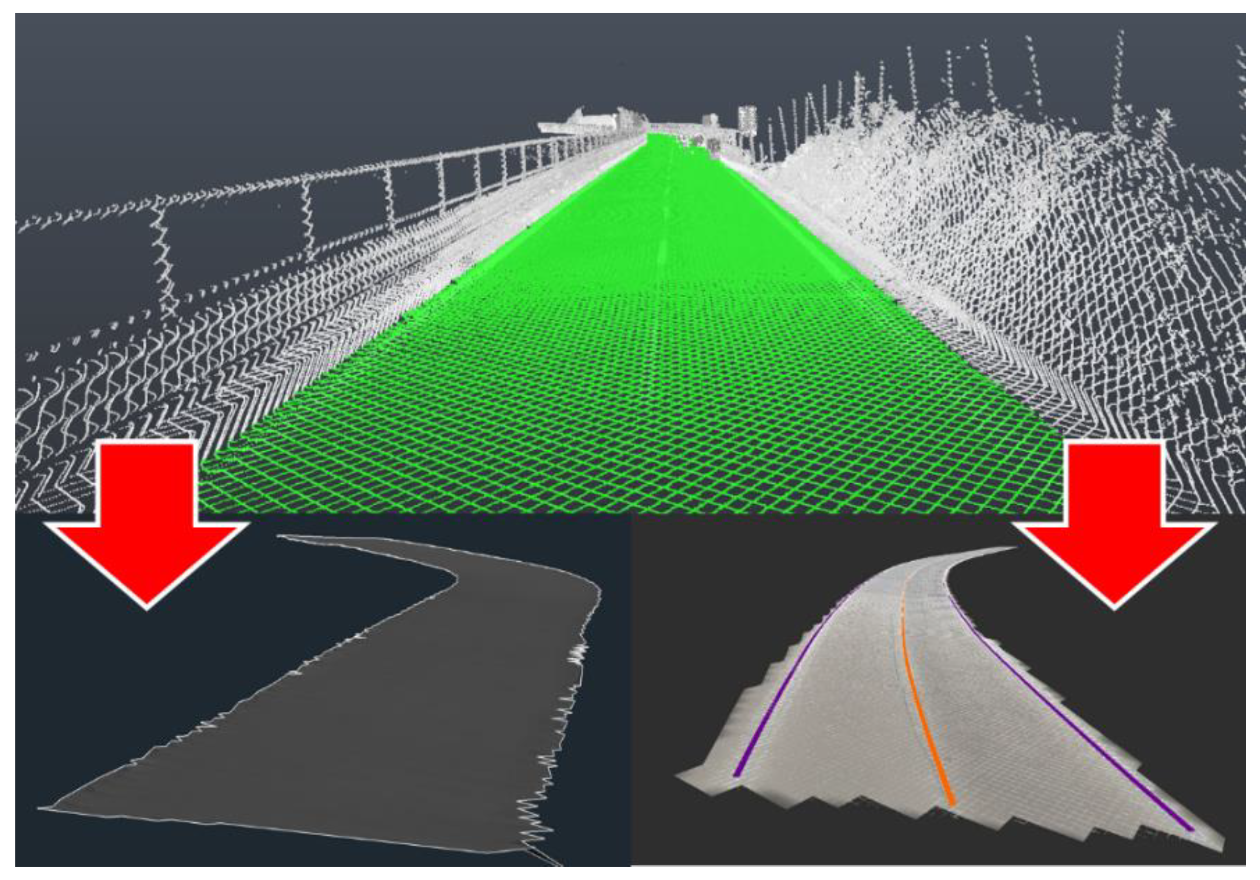
The obtained point clouds have been georeferenced by relying on the coordinates acquired by on-site GNSS measurements, which were later combined and imported into the same digital environment. The area corresponding to the pavement was isolated and used to generate a Digital Terrain Model (DTM), from the point cloud associated to the entire infrastructure (
Figure 4). These outcomes are strategic for the subsequent phases of the work. In fact, from the defined DTM, the digital model can determine the configuration of the road’s superstructure by subtracting the depth of a certain layer of the pavement, which is determined by the GPR data. Moreover, this digital element was also used to define the elevation profile and the horizontal configuration of the road that the digital model needs to emulate. Furthermore, three-dimensional polylines can be extracted from the point cloud along the road markings, to be used as ground-control targets for the parametric components of the digital model, as described in the next stages of the procedure. Additionally, these polylines can also be used to replicate the road markings into the digital model of the infrastructure once the model is created.
3.2. Creation of Digital Parametric Objects and Data Integration Processes
The subsequent phases of the proposed methodology were based on the integration of multi-source NDT data, obtained from the different surveys, in a process aimed at defining a digital BIM model of the inspected infrastructure. This was crucial for a more comprehensive interpretation of the survey’s outputs, as well as for the analysis of the infrastructure’s conditions. In addition, the BIM model of the road allowed for the analyzation of multiple sources of data (i.e., GPR, cloud points) at the same time into a single environment. For this purpose, specific parametric digital objects have been developed. These elements are capable of detecting the information obtained from the NDT surveys and adapting their configuration to generate a three-dimensional digital model of the pavement. Furthermore, one of the main advantages of the proposed procedure was related to the possibility of detecting potential damages and deteriorations, integrating the information derived from multi-source technologies into the BIM model.
For this purpose, the first parametric object created was a road’s cross-section, capable of integrating data from both GPR and MLS surveys by adapting the configuration of its layers in relation to the information provided by these inspections. As demonstrated in previous publications [
27,
28], this element was very effective for defining a three-dimensional representation of the pavement. Different types of this cross-section have been developed in order to guarantee that data obtained from both air-launched horn antenna and hand-towed ground-coupled GPR could be used. Namely, these surveys provided different resolutions and accuracy of the information related to the road’s superstructure configuration. For the current study, a cross-section capable of integrating data obtained from a hand-towed ground-coupled radar was implemented in the methodology. For the experimental application presented in this study, the first layer of the pavement’s superstructure was modeled in accordance with the GPR results.
The three-dimensional polylines that were generated from the MLS survey’s point cloud worked as targets to start the pavement’s modeling process. It was then possible to replicate the plan view and the profiles of the pavement surface by extruding the parametric cross-section along the longitudinal axis of the road, thus obtaining a 3D model that reflected the actual layout of the examined infrastructure. By combining the information from the GPR survey and the DTM provided by the MLS point cloud, the parametric section established the initial reference for calculating the depth of the HMA-bond pavement layer. Moreover, the matrix containing the HMA layer depth values was used to carry out this phase of the work, providing the needed data to the parametric elements to accurately represent the configuration of the HMA-bond layer of the pavement. This data can be effectively applied to generate a digital surface by treating this matrix as a point cloud. Three-dimensional objects were then extracted from this digital surface in order to offer the parametric cross-section of the required targets to carry out the digitalization process. Particularly, three-dimensional polylines were generated in line with the grid’s longitudinal GPR tracks. The parametric section could analyze the elevation of these polylines while it was being extruded along the infrastructure’s axis, all the while comparing it to the DTM derived from the MLS survey. The parametric section was then able to recreate the configuration of the hot mixed asphalt layer of the pavement, with appropriate estimates for the regions beneath the lane margins where GPR data were not available.
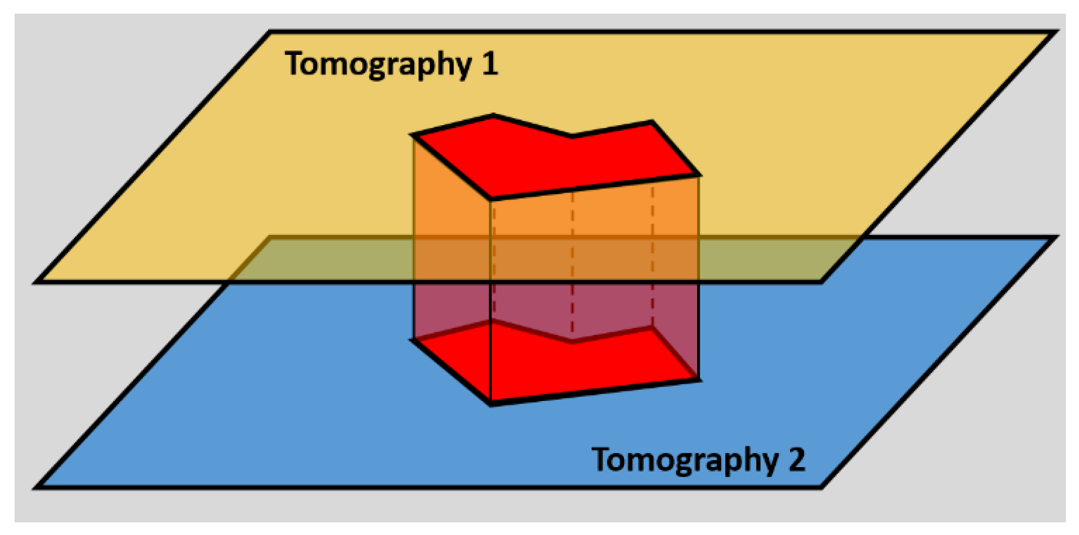
A second set of parametric objects was then created to integrate information regarding the possible distresses identified into the pavement. In particular, from the processing of GPR data, a pair of tomographies was selected to identify an area of the pavement possibly characterized by degradation. By considering the depth at which they were analyzed, a volumetric portion of the pavement that may be deteriorated can be determined between the top and bottom tomography (
Figure 5). The digital elements hereby described can import this information into the digital model of the pavement, creating a three-dimensional representation of the distress. Moreover, this digital element can be integrated with useful information associated with the identified deterioration, such as the date of the survey in which it was detected or the type of distress and its possible solutions.
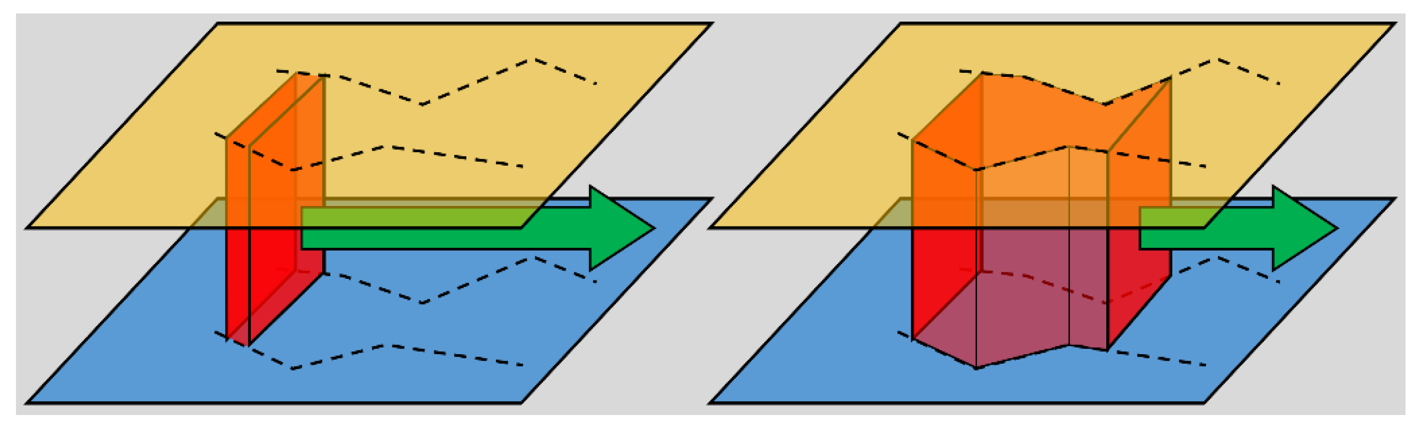
The tomographies obtained from the GPR surveys were georeferenced over the stretch of road where the surveys took place. This process allowed the acquisition of the necessary elements for the effective utilization of the parametric objects, required for the implementation of the proposed digitalization process. Subsequently, the outlines of the possible distresses were generated for each tomography by means of two polylines, one for each side of the investigated area, which were then used as targets by the designed parametric objects. Moreover, two pairs of polylines were created for each deterioration, one related to the deeper tomography and another to the more superficial one. In particular, once these were implemented, the depth of the analyzed tomographies was inserted as an input to determine where the digital model of the distress was going to be created in relation to the surface of the pavement. Furthermore, the parametric objects hereby presented functioned in the same manner of the cross-section previously described. In fact, starting from a two-dimensional shape, composed of four vertices and four sides, a three-dimensional digital element was generated by extruding this element along the detected damaged areas of the pavement’s layer. Following the outlines of these areas, the resulting model can reproduce the configuration of the distresses (
Figure 6).
4. Case Study and Results
The experimental database exploited in this study was a result of a larger survey effort on a transportation network near the city of Salerno in the Campania Region of southern Italy. The goal of these operations was to assess the network’s general resilience to natural hazards, particularly landslides. A highway, a two-lane country road and a double-track ballasted railway comprising the transportation system were selected due to the recognized geomorphological concerns involving the entire Salerno area. The complete experimental campaign covered a total length of surveys of around 20 km, in accordance with the project’s primary goal.
Regarding the current study, only a section of the highway was taken into consideration for this initial application out of the entire experimental database gathered (
Figure 7). More specifically, the motorway is composed of two carriageways with two lanes each. The carriageways are generally composed of 3 m-wide lanes, with 0.50 m-wide shoulders on each side. The proposed methodology was tested on a single carriageway of the highway, to perform the BIM digitalization process of the civil infrastructure. Both MLS and GPR surveys were conducted over an almost 9 km-long portion of the motorway, and for the latter a more thorough inspection was carried out with a hand-towed ground-coupled radar. Moreover, due to the more demanding conditions needed to perform this kind of survey, only a portion of the highway was analyzed through this instrument. As for this study, the goal was to use the data provided by this instrument to perform the digitalization process; the stretch of highway that was selected to implement the proposed procedure was the one surrounding the area where hand-towed ground-coupled GPR surveys were carried out.
4.1. NDT Survey Data Management
The MLS survey conducted over the infrastructure produced a point cloud for both carriageways. As a first step of the process, the area of the point cloud surrounding the GPR-inspected stretch of the highway was selected. The next phase consisted of the isolation of the cloud’s portion corresponding to the pavement’s surface. Subsequently, as previously described in
Section 3.1.2, it was possible to extract a DTM from the managed data, to work as a reference for the following digitalization phase. Finally, three-dimensional polylines were obtained from the point cloud in correspondence to the road markings (
Figure 8).
Moreover, the GPR survey was conducted over different prearranged grids, forming the multiple longitudinal and transversal tracks that the hand-towed ground-coupled radar needed to follow in order to obtain the expected results. For the current study, one particular grid was selected to obtain the data to carry out the proposed process. As this methodology is scalable in relation to the quantity of data provided to the digital parametric objects, a first application was implemented to test the viability and the functionality of these elements. In particular, the inspected area consisted in a 27 by 6 m grid, with intervals between longitudinal scans equal to 0.5 m, while the step between two transversal scans was 1 m.
Following the previously explained procedures, different results were obtained relating to the depth of the HMA layer of the road and the possible deteriorations present inside the pavement. In particular, an HMA thickness map describing the configuration of the first layer of the superstructure was extracted in form of a matrix of values. This information was used to create a digital surface, from which it was possible to extract a three-dimensional polyline for each longitudinal scan of the GPR. Each vertex of these polylines has a z coordinate corresponding to the HMA layer thickness in that particular spot of the grid.
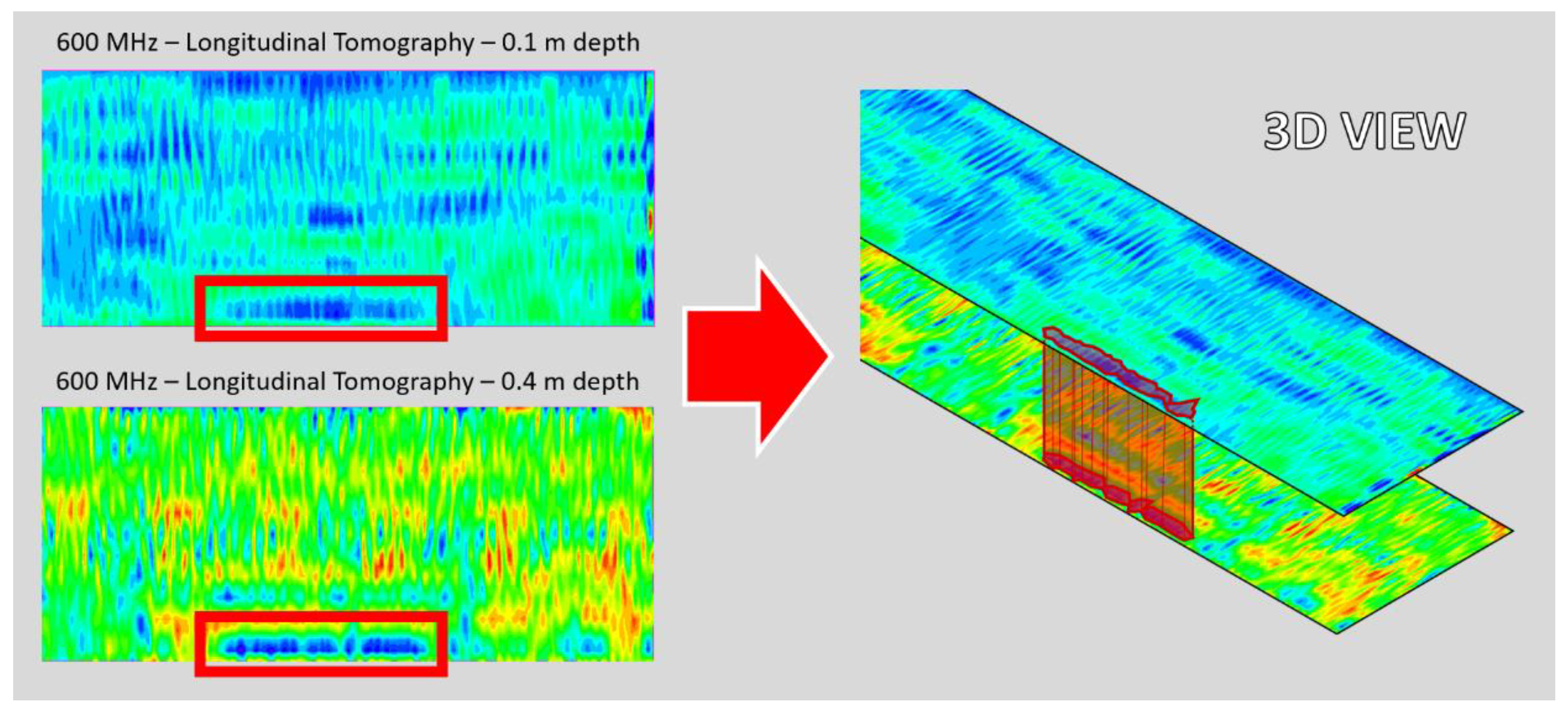
Moreover, from the same GPR data potential deteriorations of the layers of the pavement were inspected. In particular, GPR tomographies generated at 10 cm and 40 cm below the pavement surface showed an area where the signal reflection differed from the surrounding portion of the analysis. As this discrepancy was detected in the same spot of each tomography, a possible distress that extended between these sections of the road superstructure was identified, as shown in
Figure 9. These tomographies were imported into a digital environment in which it was possible to generate two polylines for each one of them, outlining the borders of the possibly deteriorated portion of the pavement.
The elements extracted from these analyses were georeferenced in relation to the coordinate system used during the surveys, to guarantee that the subsequent modeling process would refer to data correctly placed into a BIM-oriented digital environment. Therefore, at the end of the first stage of the procedure, a digital environment containing data from both MLS and GPR surveys was available. In particular, a DTM and three-dimensional polylines, corresponding to the pavement surface and the road markings, respectively, were obtained from MLS data. Moreover, GPR outputs were used to generate three-dimensional polylines, in line with the longitudinal tracks of the grid used to carry out the inspection. Furthermore, two pairs of polylines were defined as outlines of a possible deterioration inside the pavement, at a depth of 10 and 40 cm below the surface, respectively.
The subsequent phase of the process was aimed at integrating these digital elements into a single BIM model of the road pavement, implementing useful information for the monitoring and maintenance activities of this infrastructure’s asset.
4.2. Digital Modeling and Data Integration
The parametric objects defined in the current study were implemented to integrate all the previously described elements into a BIM model. The first step of the process was to generate a three-dimensional digital model of the pavement, representing its configuration on-site, by merging the outcomes extracted from MLS and GPR surveys. Subsequently, the distresses identified in the pavement could be integrated into the BIM model, to better enhance the level of detail at which the model represents the real infrastructure.
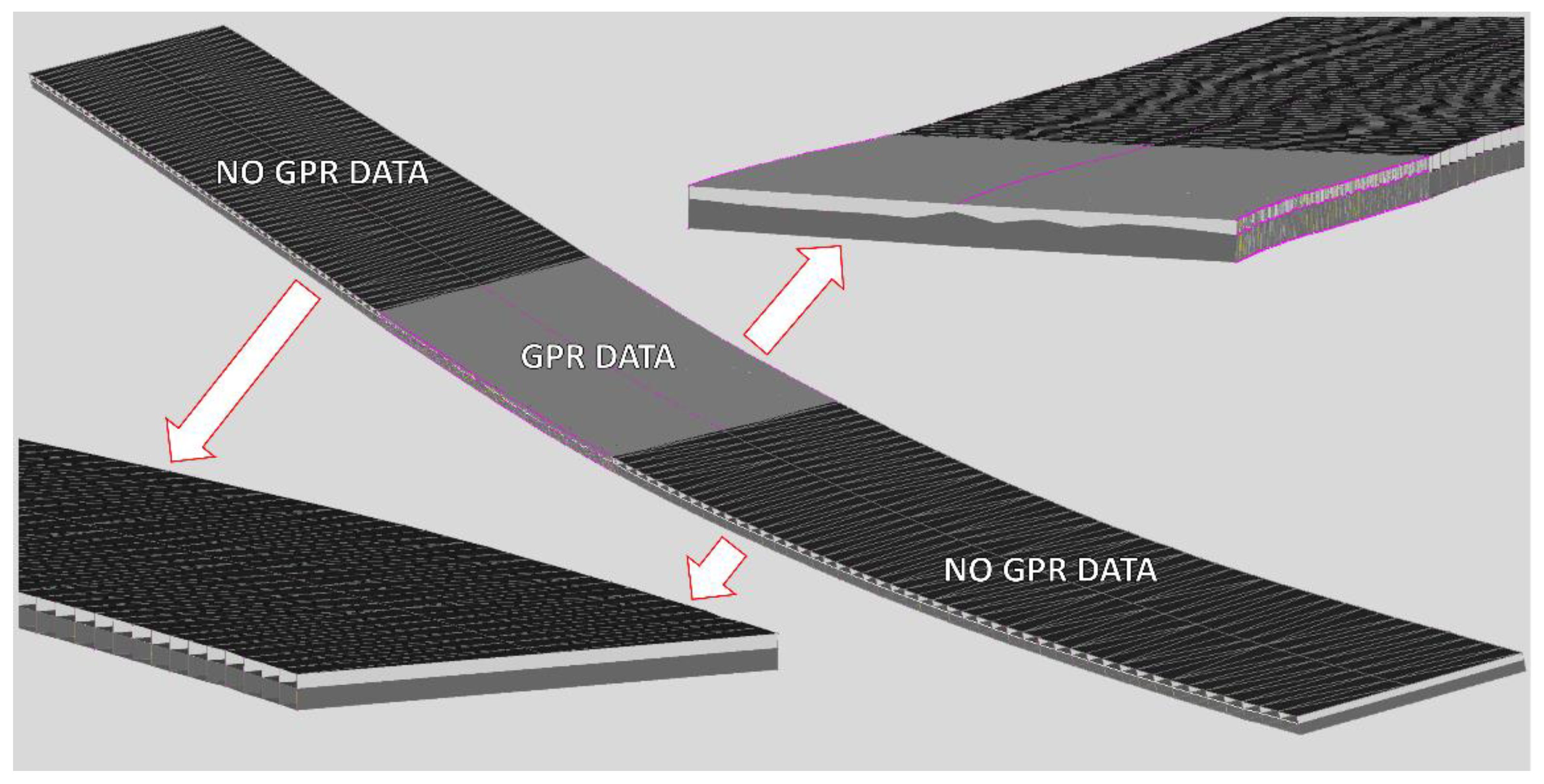
By extruding the parametric cross-section along the central three-dimensional polyline obtained by the MLS survey, it was possible to detect the DTM acquired by the same dataset, thus replicating the plan view and the profiles of the pavement surface. By targeting the other two 3D polylines, the dimension of the carriageway was reproduced, along with the possible rotation of the road’s edges. Concurrently, over the stretches of road where the GPR data were not present, a standard thickness was assigned to the HMA layer of the pavement, while on the GPR-inspected areas, the parametric cross-section analyzed the three-dimensional polylines obtained from the GPR survey. By examining the z coordinates of their vertices, the same value was then subtracted from the Laser Scanner DTM elevation, thus creating a variable configuration of the pavement layer underneath (
Figure 10).
Once the pavement digital modeling phase was complete, it was then possible to integrate into the process the information related to the possible pavement’s deterioration found underneath the surface. By implementing the previously described parametric objects, which can identify and integrate the polylines obtained from the GPR tomographies, a digital representation of the pavement distress was generated. In particular, by extruding these elements along the road’s central axis, they generated a digital model of the deterioration in the areas where those polylines are found. As the modeling phase was carried out, it was possible to implement information regarding the deterioration that was being digitalized, such as the date in which it was identified, the possible causes and remedies.
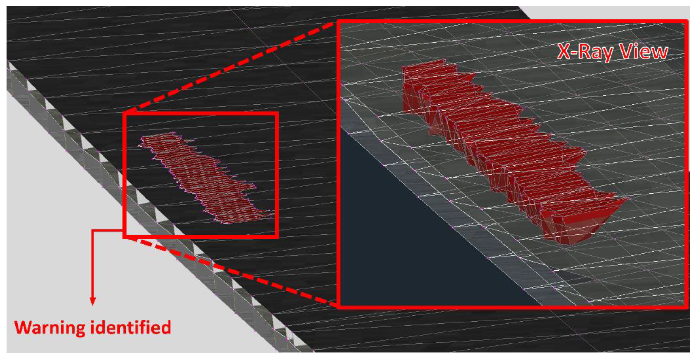
As the output of this process was a digital model representing the possible internal distress of the pavement, by analyzing the overall model from an outside point of view these elements could be missed. To ensure that any possible deteriorations of the pavement were identified and subsequently analyzed, a warning was generated whenever a “digital distress” was created inside the model. These warnings appeared outside the surface of the pavement with a predisposed offset, helping with the identification of possible deteriorated portions of the road’s superstructure.
Figure 11 shows the output of the process hereby described.
4.3. Results
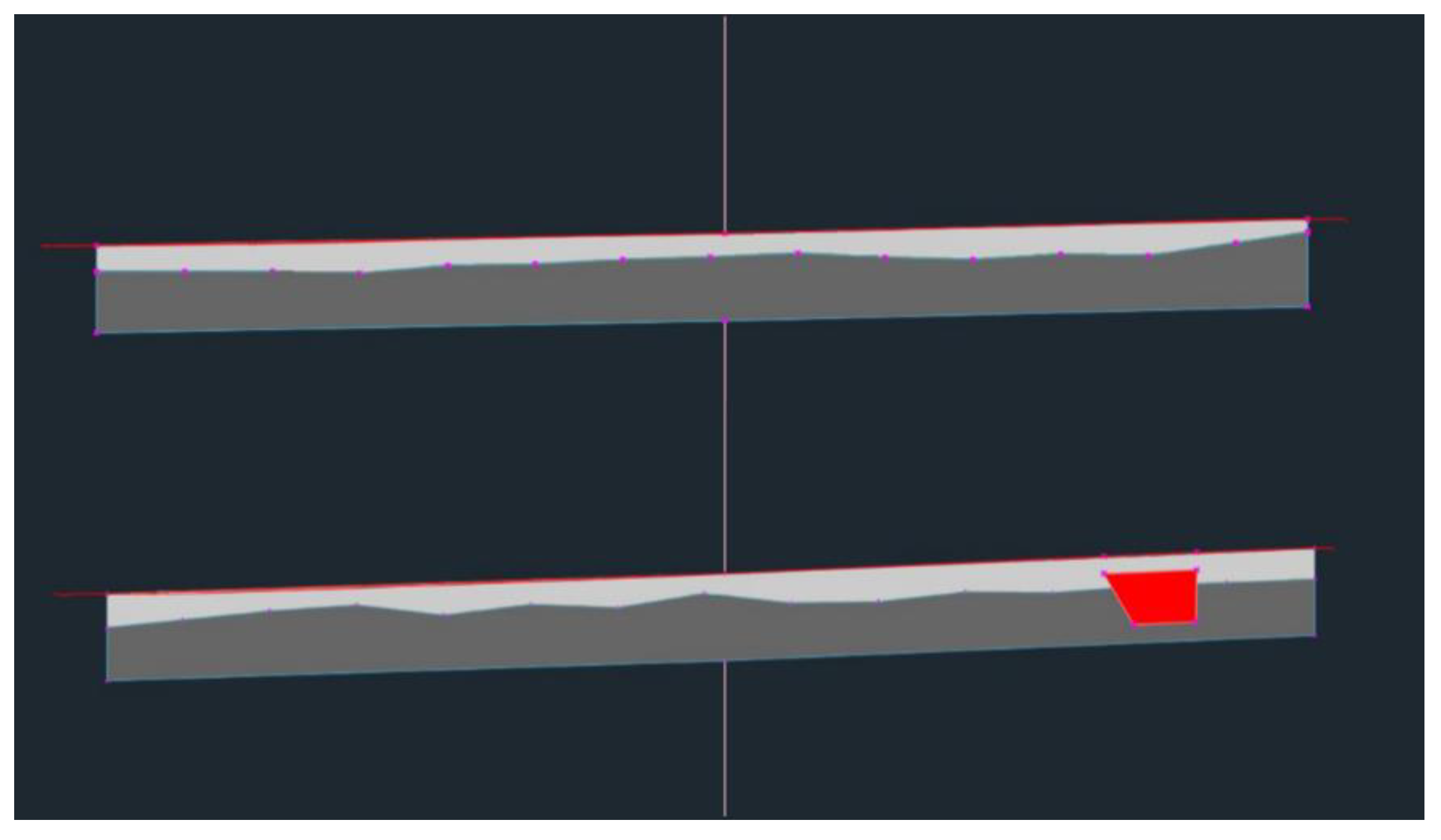
The process hereby described generated a digital informative model of an infrastructure, integrating data extracted from NDT instruments such as MLS and GPR. The resulting model followed the horizontal development and the elevation profile of the real infrastructure that has been surveyed, while also reproducing its pavement’s HMA layer configuration. Once both MLS and GPR data have been integrated into the digital model, it was then possible to proceed to a more thorough analysis of the infrastructure, by examining it in a three-dimensional environment. Moreover, one of the main innovations of the present procedure was the possibility to evaluate a portion of the road, including the deep layers of the pavement, typically not accessible by on-site inspections. A subsequent analysis included the assessment of the volumes for each layer of the pavement, as well as the evaluation of volume of the pavement that was affected by possible deteriorations. Furthermore, different kinds of distress could be identified, and the resulting analysis could evaluate the resulting volumes of each one. Such volumes could be automatically extracted from the model’s information, by relying on specific unique codes assigned to each element of the BIM model. Moreover, while analyzing the possible deteriorations of the pavement, it was possible to refer only to a specific survey, as data outputs obtained in different dates are assigned different codes. Furthermore, these analyses could be carried out both in a three-dimensional environment and by sectioning the model in different parts and analyzing the resulting cross-sections.
Figure 12 shows an example of two cross-sections of the generated model, as one of them was created in an area of the pavement where a distress was identified (represented in red).
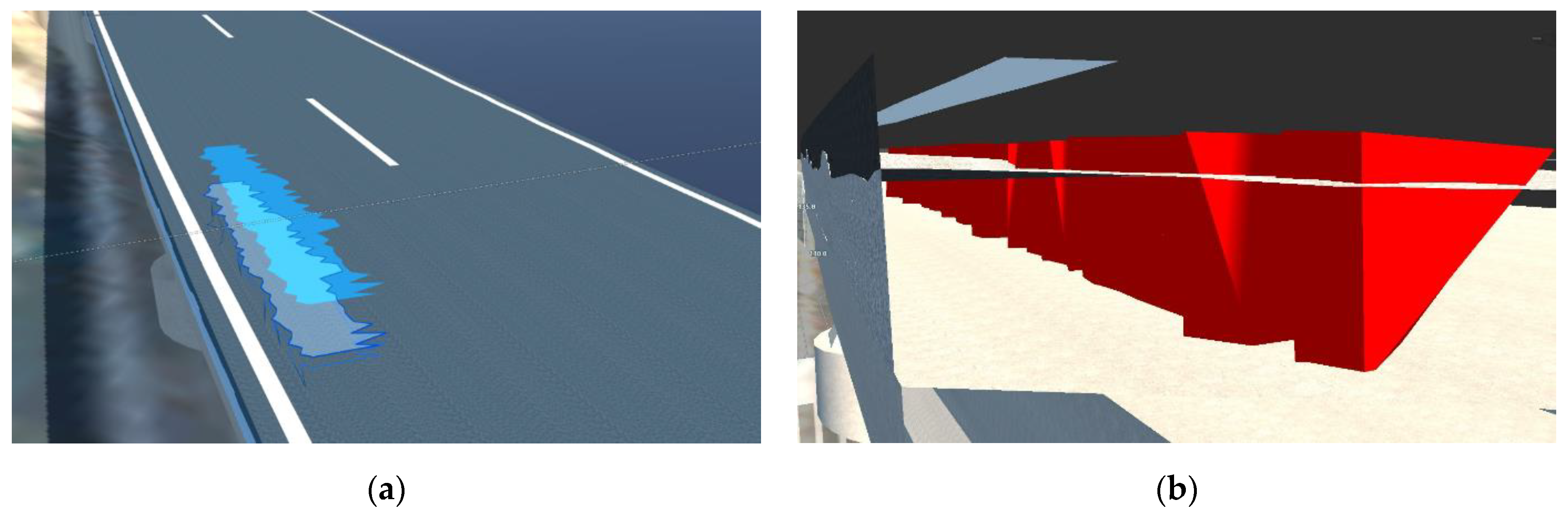
Additionally, the BIM model of the infrastructure can be imported into a realistic digital environment, to examine its conditions in a three-dimensional space. This allowed for a more direct and more effective analysis of the potential distresses and configuration of the pavement’s layers, as shown in
Figure 13. The resulting digital model can also be investigated in its different components, evaluating the information integrated during the modeling phases. In particular, by selecting the digital models of the detected deteriorations, a table with all the regarding information was shown, detailing which kind of distress it was, the date of the related survey and other useful data. By relying on this methodology, a unified BIM model that functions as a database for different survey outputs was defined. This model can be updated over time to evaluate possible developments of deteriorations found inside the road’s pavement and subsequently to plan maintenance activities.
5. Conclusions and Future Developments
The main aim of this study was to develop a methodology to integrate data obtained from NDT surveys in the digitalization process of a BIM model of a linear transport infrastructure. Making use of different data outputs and specially designed digital parametric objects, the integration of MLS and GPR information was successfully carried out. The point cloud generated from the MLS survey allowed to define the geometric characteristic of the road, its dimensions and both its horizontal configuration and elevation profile. Moreover, it provided the reference from which to determine the thickness of the pavement, by generating a DTM of the road’s surface. The data provided by the GPR survey were implemented to define the configuration HMA layer of the pavement and its thickness over a certain area of the model, where the data were collected and processed. Moreover, the information obtained by this survey allowed determining parts of the pavement possibly affected by damages and deteriorations in the deep layers of the superstructure. Digital representations of these distresses were defined, implementing useful information into the BIM model. The resulting digital model of the infrastructure functioned as a storage for both the MLS and GPR data, replicating the configuration of the infrastructure and its pavement. It was also used to analyze the road’s conditions and the degradations that may affect its assets, even in areas that cannot be inspected by operators on-site, such as the deep layers of the pavement. The methodology hereby presented could prove an efficient tool for road administrators and stakeholders that need to monitor and maintain linear transport infrastructures. By relying on these BIM models, an effective process for data storage and infrastructure maintenance planning can be defined, avoiding data loss and ensuring that analyses can be carried out over time.
This study represents a promising application for NDT data integration in BIM models and is effective in underlying the potential of this methodology in the field of transport infrastructure engineering. Furthermore, as this study has had some limitations in its development, future perspectives are hereby presented. A first implementation to the methodology could be the analysis of different layers of the pavement by means of GPR analysis. This would allow to define a more detailed model of the pavement, describing the configuration of the entire road’s superstructure. Moreover, more thorough analyses could be carried out on a model comprised of all the different layers of the pavement.
Further implementations to the methodology could be the integration of different data into the model. Numerous NDT methods are currently in use in the monitoring activities of transport infrastructure, and the resulting data outputs could prove a useful implementation to the BIM model, improving its level of detail and depicting more thoroughly the real infrastructure. Moreover, different types of analyses could be carried out if the model contained information provided by these surveys.
In the digitalization process of possible pavement’s distresses, different developments have been identified to guarantee a better depiction of the road’s conditions. The digital models of the pavement’s deteriorations could be divided into different components in relation to the pavement’s layers they are affecting. The related warnings over the infrastructure’s model would then immediately show the different areas of the road’s superstructure that are affected by degradation and their possible causes. Furthermore, an interesting development of this study would be to test the proposed methodology in the context of a Pavement Management System (PMS), defining a first application for a BIM-based PMS. To allow this process, preliminary operations related to the identification of pavement distresses and possible solutions through the use of BIM models need to be tested.
Overall, the proposed methodology showed the potential of integrating BIM models in the monitoring phases of a linear transport infrastructure, in relation to data acquisition and storage, as well as the possible analyses that can be carried out by relying on multiple data sources in a single environment. As more studies and applications are developed in the field of BIM for linear transport infrastructure, novel monitoring and maintenance methods are going to be determined, improving civil engineering practices.
Author Contributions
Conceptualization, L.B., F.D. and A.N.; methodology, L.B., F.D., A.N. and L.B.C.; validation, L.B., A.N. and L.B.C.; investigation, L.B., F.D., A.N., V.G., L.B.C. and J.R.D.M.; data curation, L.B. and L.B.C.; writing—original draft preparation, L.B. and L.B.C.; writing—review and editing, L.B., F.D., A.N., V.G., L.B.C. and J.R.D.M.; supervision, F.D.; project administration, F.D.; funding acquisition, F.D. and L.B.C. All authors have read and agreed to the published version of the manuscript.
Funding
The research is supported by the Italian Ministry of Education, University and Research under the National Project “Extended resilience analysis of transport networks (EXTRA TN): Towards a simultaneously space, aerial and ground sensed infrastructure for risks prevention”, PRIN 2017, Prot. 20179BP4SM.
Data Availability Statement
Data sharing is not applicable to this article.
Conflicts of Interest
The authors declare no conflict of interest.
References
- Gagliardi, V.; Tosti, F.; Bianchini Ciampoli, L.; Battagliere, M.L.; D’Amato, L.; Alani, A.M.; Benedetto, A. Satellite Remote Sensing and Non-Destructive Testing Methods for Transport Infrastructure Monitoring: Advances, Challenges and Perspectives. Remote Sens. 2023, 15, 418. [Google Scholar] [CrossRef]
- Tosti, F.; Gagliardi, V.; D’Amico, F.; Alani, A.M. Transport infrastructure monitoring by data fusion of GPR and SAR imagery information. Transp. Res. Proc. 2020, 45, 771–778. [Google Scholar] [CrossRef]
- Benedetto, A.; Manacorda, G.; Simi, A.; Tosti, F. Novel perspectives in bridges inspection using GPR. Nondestruct. Test. Eval. 2012, 27, 239–251. [Google Scholar] [CrossRef]
- Al-Qadi, I.L.; Lahouar, S. Use of GPR for thickness measurement and quality control of flexible pavements. J. Assoc. Asph. Paving Technol. 2004, 73, 28. [Google Scholar]
- Elseicy, A.; Alonso-Díaz, A.; Solla, M.; Rasol, M.; Santos-Assunçao, S. Combined use of GPR and other NDTs for road pavement assessment: An overview. Remote Sens. 2022, 14, 4336. [Google Scholar] [CrossRef]
- Xiong, C.; Yu, J.; Zhang, X. Use of NDT systems to investigate pavement reconstruction needs and improve maintenance treatment decision-making. Int. J. Pavement Eng. 2021, 1–15. [Google Scholar] [CrossRef]
- Merkle, D.; Frey, C.; Reiterer, A. Fusion of ground penetrating radar and laser scanning for infrastructure mapping. J. Appl. Geod. 2021, 15, 31–45. [Google Scholar] [CrossRef]
- Xie, X.; Zeng, C. Non-destructive evaluation of shield tunnel condition using GPR and 3D laser scanning. In Proceedings of the 2012 14th International Conference on Ground Penetrating Radar (GPR), Shanghai, China, 4–8 June 2012; pp. 479–484. [Google Scholar]
- Directive 2004/18/EC; Directive 2014/24/EU of the European Parliament and of the Council of 26 February 2014 on Public Procurement and Re-Pealing. European Commission: Brussels, Belgium, 2014.
- DM 560/2017; Ministero Delle Infrastrutture e Della Mobilità Sostenibile, Modifiche al. European Commission: Brussels, Belgium, 2021.
- Ministero Delle Infrastrutture e dei Trasporti. Lgs: Disposizioni Urgenti per la Città di Genova, la Sicurezza Della Rete Nazionale Delle Infrastrutture e dei Trasporti, Gli Eventi Sismici del 2016 e 2017, il Lavoro e le Altre Emergenze; European Commission: Brussels, Belgium, 2018.
- 2017/560/DM; Ministero Delle Infrastrutture e dei Trasporti: Modalità e i Tempi di Progressiva Introduzione dei Metodi e Degli Strumenti Elettronici di Modellazione per L’edilizia e le Infrastruttur. European Commission: Brussels, Belgium, 2017.
- Liu, H.; Sydora, C.; Altaf, M.S.; Han, S.; Al-Hussein, M. Towards sustainable construction: SIM-enabled design and planning of roof sheathing installation for prefabricated buildings. J. Clean. Prod. 2019, 235, 1189–1201. [Google Scholar] [CrossRef]
- Wu, S.; Zhang, N.; Luo, X.; Lu, W.-Z. Multi-objective optimization in floor tile planning: Coupling BIM and parametric design. Autom. Constr. 2022, 140, 104384. [Google Scholar] [CrossRef]
- Acerra, E.M.; Busquet, G.F.D.; Parente, M.; Marinelli, M.; Vignali, V.; Simone, A. Building Information Modeling (BIM) Application for a Section of Bologna’s Red Tramway Line. Infrastructures 2022, 7, 168. [Google Scholar] [CrossRef]
- Hinostroza, P.; Granados, J.; Bravo, A. Proposal to Implement the BIM Methodology in Road Infrastructure Projects Optimizing Workflows. In Proceedings of the Congreso Internacional de Innovación y Tendencias en Ingeniería (CONIITI), Bogotá, Colombia, 29 September–1 October 2021; pp. 1–6. [Google Scholar]
- Moreno Bazán, Á.; Alberti, M.G.; Arcos Álvarez, A.; Trigueros, J.A. New Perspectives for BIM Usage in Transportation Infrastructure Projects. Appl. Sci. 2020, 10, 7072. [Google Scholar] [CrossRef]
- Osello, A.; Rapetti, N.; Semeraro, F. BIM Methodology Approach to Infrastructure Design: Case Study of Paniga Tunnel. IOP Conf. Ser. Mater. Sci. Eng. 2017, 245, 062052. [Google Scholar] [CrossRef]
- van Eldik, M.A.; Vahdatikhaki, F.; dos Santos, J.M.O.; Visser, M.; Doree, A. BIM-based environmental impact assessment for infrastructure design projects. Autom. Constr. 2020, 120, 103379. [Google Scholar] [CrossRef]
- van Eldik, M.A.; Santos, J.; Vahdatikhaki, F.; Visser, M.; Dorée, A. BIM-based life cycle assessment framework for infrastructure design. In Proceedings of the 27th International Workshop on Intelligent Computing in Engineering, EG-ICE 2020, Online, Germany, 1 July 2020–4 July 2020; Volume 114, p. 254. [Google Scholar]
- Biancardo, S.A.; Capano, A.; de Oliveira, S.G.; Tibaut, A. Integration of BIM and Procedural Modeling Tools for Road Design. Infrastructures 2020, 5, 37. [Google Scholar] [CrossRef]
- Chong, H.-Y.; Lee, C.-Y.; Wang, X. A mixed review of the adoption of Building Information Modelling (BIM) for sustainability. J. Clean. Prod. 2017, 142, 4114–4126. [Google Scholar] [CrossRef]
- Calvi, G.M.; Moratti, M.; O’Reilly, G.J.; Scattarreggia, N.; Monteiro, R.; Malomo, D.; Calvi, P.M.; Pinho, R. Once upon a Time in Italy: The Tale of the Morandi Bridg. Struct. Eng. Int. 2019, 29, 198–217. [Google Scholar] [CrossRef]
- Panah, R.S.; Kioumarsi, M. Application of Building Information Modelling (BIM) in the Health Monitoring and Maintenance Process: A Systematic Review. Sensors 2021, 21, 837. [Google Scholar] [CrossRef]
- Maltini, F.; Curreli, L.; Quaquero, E.; Rubiu, G.; Coni, M. Applying Building Information Modeling to Road Pavements Management. In Proceedings of the Computational Science and Its Applications–ICCSA 2021: 21st International Conference, Cagliari, Italy, 13–16 September 2021; Volume 12958, pp. 145–160. [Google Scholar]
- Aziz, Z.; Riaz, Z.; Arslan, M. Leveraging BIM and Big Data to deliver well maintained highways. Facilities 2017, 35, 818–832. [Google Scholar] [CrossRef]
- D’Amico, F.; Bertolini, L.; Napolitano, A.; Manalo, D.R.J.; Gagliardi, V.; Bianchini Ciampoli, L. Implementation of an interoperable BIM platform integrating ground-based and remote sensing information for network-level infrastructures monitoring. In Proceedings of the SPIE 12268, Earth Resources and Environmental Remote Sensing/GIS Applications XIII, 1226801, Berlin, Germany, 15 November 2022; Front Matter. Volume 12268, pp. 112–122. [Google Scholar] [CrossRef]
- D’Amico, F.; Bianchini Ciampoli, L.; Di Benedetto, A.; Bertolini, L.; Napolitano, A. Integrating Non-Destructive Surveys into a Preliminary BIM-Oriented Digital Model for Possible Future Application in Road Pavements Management. Infrastructures 2022, 7, 10. [Google Scholar] [CrossRef]
- Bosurgi, G.; Pellegrino, O.; Sollazzo, G. Pavement condition information modelling in an I-BIM environment. Int. J. Pavement Eng. 2021, 23, 4803–4818. [Google Scholar] [CrossRef]
- Abbondati, F.; Biancardo, S.A.; Palazzo, S.; Capaldo, F.S.; Viscione, N. I-BIM for existing airport infrastructures. Transp. Res. Proc. 2020, 45, 596–603. [Google Scholar] [CrossRef]
- Guerra de Oliveira, S.; Tibaut, A.; Dell’Acqua, G. Airport Pavement Management Systems: An Open BIM Approach. Lect. Notes Civ. Eng. 2020, 48, 450–459. [Google Scholar]
- Jol, H.M. Ground Penetrating Radar Theory and Applications; Elsevier: Amsterdam, The Netherlands, 2008. [Google Scholar]
- Daniels, D.J. Ground Penetrating Radar, 2nd ed.; The Institution of Electrical Engineers: London, UK, 2004. [Google Scholar]
- De Blasiis, M.R.; Di Benedetto, A.; Fiani, M. Mobile laser scanning data for the evaluation of pavement surface distress. Remote Sens. 2020, 12, 942. [Google Scholar] [CrossRef]
- Kumar, P.; McElhinney, C.P.; Lewis, P.; McCarthy, T. Automated road markings extraction from mobile laser scanning data. Int. J. Appl. Earth Obs. Geoinf. 2014, 32, 125–137. [Google Scholar] [CrossRef]
| Disclaimer/Publisher’s Note: The statements, opinions and data contained in all publications are solely those of the individual author(s) and contributor(s) and not of MDPI and/or the editor(s). MDPI and/or the editor(s) disclaim responsibility for any injury to people or property resulting from any ideas, methods, instructions or products referred to in the content. |
© 2023 by the authors. Licensee MDPI, Basel, Switzerland. This article is an open access article distributed under the terms and conditions of the Creative Commons Attribution (CC BY) license (https://creativecommons.org/licenses/by/4.0/).


 ,
, 


