
Enhancement Seismic Response of a Bored Tunnel Using Isolation for the Challenge of a Faulted Rock Crossing

1
Faculty of Engineering, Damietta University, Damietta 34517, Egypt
2
Egyptian National Authority for Tunnels, Cairo 11511, Egypt
*
Author to whom correspondence should be addressed.
Infrastructures 2024, 9(4), 66; https://doi.org/10.3390/infrastructures9040066
Submission received: 8 February 2024
/
Revised: 13 March 2024
/
Accepted: 26 March 2024
/
Published: 27 March 2024
(This article belongs to the Section Infrastructures and Structural Engineering)
Abstract
:The tunnel boring method (TBM) is a widely used and effective tunneling technology in various rock mass quality circumstances. A “faulted rock mass” can range from a highly fractured rock mass to a sheared weak rock mass, making the ground conditions challenging for tunneling, especially for TBMs. “Faulted rock” significantly affects hard rock TBMs, primarily due to the TBM’s high geological risk and poor flexibility. TBMs require careful planning and preparation, starting with preliminary assessments. This study investigates the impact of establishing an isolation material between a circular tunnel and the adjacent faulting rock on seismic response. The two parts of the parametric analysis for the isolation material utilized in the model look at how changes in the mechanical characteristics of the material, such as the shear modulus of the rock and the fault, affect the stresses created in the tunnel. The second section examines how changes in the isolation width concerning the fault width affect the stresses and displacements produced in the tunnel. Additionally, the effectiveness of isolating the tunnel during sudden changes in the characteristics of the rock was investigated under seismic loading perpendicular to the tunnel and parallel to the tunnel. The finite element approach was utilized to model the TBM tunnel and the neighboring rock with a fault or sudden change in the rock using Midas/GTS-NX, simulating the interactions between the rock and the tunnel. Time-history analysis using the El Centro earthquake was conducted to calculate the stresses in the tunnels during seismic events. Peak ground accelerations between 0.10 g and 0.30 g were utilized for excitation. A time step of 0.02 s and a length of 10 s for the seismic event were used in the analysis, with traditional grout pea gravel vs. the isolation layer. Comparisons were made between the absolute stresses (the greatest possible values) in the normal tunnel section (Sxx) and those induced in the tunnel with traditional grout and with isolation. Furthermore, the study of vertical displacement was taken into consideration. The seismic isolation method is highly effective in improving the seismic safety of bored tunnels. The results show that the significant values of the ratio between the shear modulus of isolation and the surrounding soil should be between 0.2% and 0.4%. Where parts of the tunnel run through a fault, the effective length of isolation should be between one and two times the fault width. The dynamic behavior of the tunnel with isolation is better than that with traditional grout. Generally, when isolation is used for any length, it reduces the stresses at the area of sudden change. Consequently, engineering assessments from both structural and geotechnical engineering viewpoints are now required for these unique constructions. An underground structure’s safety should be evaluated by the designer to ensure that it can sustain various applied loads, taking into account seismic loads in addition to construction and permanent static loads. Tunnels may be especially vulnerable in areas where the composition of the soil or rock varies.
1. Introduction
Bored tunnels crossing rock are often built in fault fracture zones due to line-type requirements. Instability of the rock mass can lead to collapse, causing economic and physical damage. Tunnel engineering depends on the stability of the surrounding rock, influenced by the fault’s slope angle and breadth [1,2]. Research on tunnel rock stability has gained popularity using various analytical techniques, including physical model experimental, analytic, and numerical simulation methods. These methods assess the stability of tunnel rock and provide valuable insights into tunnel safety [3,4,5,6,7,8,9]. Different methodologies have unique attributes but also constraints, like time and resource investment in physical model experiments. Analytical solutions depend on assumptions, limiting their applicability in complex tunnels.
Advancements in computer technology have made numerical simulation an efficient method for analyzing the stability of rock surrounding tunnels. Conceptual models like finite element models (FEMs), boundary element models (BEMs), and discrete element models (DEMs) have been suggested for simulation. The finite element approach is widely used in tunnel engineering for predicting tunnel stability [4,7,10,11,12,13,14]. Recent research explored fault fracture zones in tunnels through numerical analyses. Kim and colleagues [15] studied tunnel collapse methodologies and reasons, while Zhao and Janutolob [16] introduced a 3D FEM simulator for tunnel boring machine excavation.
Dalgıc [17] suggested deformation and failure processes in Tuzla Tunnel excavations, Shrestha and Panthi [18] examined the groundwater impact on faulted rock, and Fraldi and Guarracino [19] examined plasticity theory. A basic analytical technique was used to forecast plastic collapse in circular rock tunnels using a translational 3D multiblock failure mechanism. Accurately forecasting of collapse conditions remains a challenge in subterranean engineering [20,21,22,23]. Xiong and colleagues [24] numerically evaluated tunnel lining force parameters, considering the benefits of numerical modeling and the deformation and supporting effect of spray anchors impacted by faults. A two-dimensional FEM was developed [25] to analyze the behavior of surrounding-rock construction mechanics at different fault sites. The tunnel’s stability was studied through centrifuge model tests, numerical simulations, and research on the arching effect in soft clayey soil. Osman and colleagues [26] proposed a kinematic plastic solution for ground motions in an undrained clay layer enclosing a shallow tunnel, primarily using numerical modeling. Wang and colleagues [27] developed a 3D numerical model created to simulate tunnel excavation at the Wuzhuling Tunnel on the Zhuyong Highway. The model was analyzed using the finite element method, focusing on deformation and stress distribution in the fault fracture zone. The model’s stability and influence on tunnel-surrounding rocks were also studied. The results can guide design evaluation in fault fracture zones.
Tunnels are widely used in mountainous regions because of their resilience against geological and seismic hazards, but may sometimes need to traverse weak or faulting zones [28,29,30,31,32,33,34]. Recent earthquakes, such as the 1999 Chi-Chi, 1999 Kocaeli, and 2008 Wenchuan earthquakes, have caused significant destruction to tunnels despite their higher earthquake resistance than surface buildings [34,35,36,37,38,39,40]. Seismic research indicates that fault-crossing regions are highly seismically active, causing significant damage to tunnels [41,42,43,44,45,46]. Therefore, investigating mitigating strategies is crucial for these areas [47,48,49,50].
Scholars have proposed flexible, collaborative tunnel methods, allowing linings to adjust to fault movement and reducing damage [51,52]. Flexible joints used in subterranean structures have successfully minimized earthquake damage [53,54]. Faults in geology are movement-induced fractures in the Earth’s crust, causing earthquakes and other seismic events. Monitoring seismic activity is crucial for earthquake risk assessment [55,56,57]. A review of tunnels in major earthquake-prone areas revealed three incidents of damage or faulting, including twin tunnels in Bolu, Turkey, indicating that earthquake-resistant constructions are not always effective, and seismic surface ruptures are secondary.
The research by Zhang and colleagues [58,59] challenges the belief that tunnels have exceptional seismic response to earthquakes. They examined the seismic response of tunnels and subterranean structures due to seismic damage. The study discusses the seismic response of fault-crossing tunnels and uses two aseismic philosophies to examine various measures. The optimal design involves confirming fault activity, estimating displacement and earthquake intensity, and combining measures to create composite measures. The work aims to improve the understanding of the fault-crossing tunnel seismic response.
Ma and colleagues [60] investigated the mechanical properties of foamed concrete in rock tunnels, focusing on its potential as a seismic isolation material due to its energy absorption capacity. Their tests showed that the concrete’s density significantly influences its mechanical characteristics, with solid strain rate dependence and volumetric compressibility. The findings suggest the potential of foamed concrete in tunnels. Cui and colleagues [61] investigated the earthquake resilience of tunnels at the intersection of soft and hard rocks during strong earthquakes. They used numerical models to investigate the impact of the soft rock ratio on tunnel safety. The study found that the isolation layer reduced the secondary lining stress and seismic effects with varying dip angles. The study recommends using isolation techniques and structural reinforcements when structures cross the interface between soft and hard rock.
Shahidi and colleagues [62] examined the Jingzhai Tunnel’s substantial deformation mechanism using geological investigation, theoretical research, numerical modeling, and other methods. They investigated how advanced reinforcement techniques affect control, highlighting the low strength of the surrounding rock and the asymmetric deformation caused by the tunnel’s fault fracture zone. The study suggests that a grouting radius of two meters can efficiently regulate deformation.
The present study examines the effects of installing an isolation material between a circular tunnel and the neighboring faulting rock on the seismic response. The stresses generated within the tunnel are examined in the two sections of the parametric analysis of the isolation material employed in the model. These sections analyze the impact of modifications on the material’s mechanical properties, including the shear modulus of the rock and the fault. The subsequent section investigates the impact of variations in the isolation width with respect to the fault width on the tunnel’s generated stresses and displacements. Additionally, an investigation was conducted to assess the efficacy of tunnel isolation in the face of abrupt alterations in the rock’s properties, utilizing seismic loads both perpendicular and parallel to the tunnel. Using the finite element method, we simulated the interactions between the rock and the TBM tunnel utilizing Midas/GTS-NX and the adjacent rock with a fault or a rapid shift. The stresses in the tunnels during seismic events were computed by employing time-history analysis and the El Centro earthquake.
2. Faulted Rock
“A planar or gently curved fracture in the rocks of the Earth’s crust, where compressional or tensional forces cause relative displacement of the rocks on opposite sides of the fracture” is the definition of a fault given by geologists. There are several types of faulting, such as normal and reverse faulting, in which the rock masses slide past each other vertically, and strike-slip faulting, in which the rock masses slide past each other horizontally. There is a large number of non-vertical faults and fault zones. They make an angle with the Earth’s surface, which is a horizontal plane. This is known as the fault’s dip angle. The fault’s strike is where the horizontal plane and the fault cross. Associated structures, like drag folds or secondary faulting, have the potential to destabilize and weaken the nearby ground, as shown in Figure 1.
Different criteria can be used to classify faults in different ways. These fault categories are based on many classifications, as shown in Figure 2.
The development of cracks or weak areas where movement has occurred in the crust of the planet is known as faulting. Faulting is the result of several factors and processes in geology. The main reasons for faulting are summarized in Figure 3. Tectonic forces are divided into normal (compression and tension) shear stress. Compression: Reverse or thrust faults can emerge due to compressional forces acting upon tectonic plates when they converge or move in the direction of one another. The Earth’s crust becomes thicker and shorter, which causes these faults. Tension: Extensional stresses produced by tectonic plates moving apart lead to typical fault formation. Stretching and thinning of the Earth’s crust cause normal faults. Shear stress: Along transform plate boundaries, shear stress results from tectonic plates sliding past one another horizontally. Strike-slip faults, in which rock blocks both sides of the fault slip in opposing directions horizontally, are formed due to this kind of stress.
2.1. Seismic Response of a Tunnel in Faulted Rock
Seismic activity is frequently linked to faults, which can also cause earthquakes. Rocks moving along a fault plane release stress energy that has been stored, which can cause seismic occurrences that could be harmful, surface rupture, and ground shaking. Assessing and being ready for earthquake hazards requires understanding fault locations and behaviors. Faults can also produce earthquakes and are commonly associated with seismic activity. Ground shaking, surface rupture, and potentially dangerous seismic events can result from rocks moving along a fault plane, releasing accumulated stress energy. Understanding fault locations and behaviors is essential to assessing and preparing for earthquake hazards.
The sections of tunnels that are most susceptible to collapse and other serious damage during an earthquake are parts that span a fault, according to the seismic damage examinations of numerous tunnels. However, this is not the case for a tunnel traversing a fault; it may survive earthquakes comparatively undamaged or with less severe damage. As such, it is imperative to determine the type of fault-crossing tunnel that is most vulnerable to earthquake damage.
Faults and tunnel-surrounding rock’s behaviors vary during an earthquake because of their differing material characteristics. Due to this type of differential movement, the tunnel will experience back-and-forth shear action on the interface. Shear failure or tension cracks parallel to the tunnel lining contact may result from the shear action. Weak tunnel sections may collapse when the plastic zone of a fault created by the earthquake combines with fracture formation, expansion, and transfixion. Factors related to tunnel damage are summarized in Figure 4.
Generally, the inertia of a tunnel is small compared to that of the surrounding geologic medium. Therefore, it is reasonable to perform tunnel deformation analysis using pseudo-static or pseudo-dynamic analysis, in which displacements or displacement time histories are statically applied to the soil–structure system. Dynamic time-history analysis can be used to further refine the analysis as necessary, particularly when some portion(s) of the tunnel structure can respond dynamically under earthquake loading, i.e., in cases where the inertial effect of the tunnel structure is considered to be significant. In a dynamic time-history analysis, the entire soil–structure system is subject to dynamic excitations using ground motion time histories as input at the base of the soil–structure system. The ground motion time histories used for this purpose should be developed to match the target design response spectra and have characteristics that are representative of the seismic environment of the site and the site conditions. It should be noted that the side boundary conditions in a dynamic time-history analysis should be such that outgoing seismic waves are allowed to pass through instead of being trapped within the soil–structure system being analyzed. Special energy-absorbing boundaries should be incorporated into the model to allow for the radiation of the seismic energy rather than trapping it.
Only in a detailed dynamic analysis is the coupling between the response in the longitudinal direction (i.e., along the tunnel axis) and along the cross-section (i.e., along the transversal direction) considered.
2.2. Seismic Protection of Tunnels in Faulted Rock
In the past, the majority of underground structures were constructed without taking seismic behavior into account because, on the whole, tunnel performance during earthquakes was better than that of aboveground constructions. In certain instances, the same seismic factors that apply to aboveground structures were also taken into account when designing underground structures. An accurate assessment of the stresses under seismic waves is required in order to optimize the tunnel seismic design. According to the local seismic hazard forecasts, performance-based seismic design should seek to both keep the tunnels operational during the more common occurrences (of lower intensity) and prevent the loss of human life during exceptional earthquakes (of higher intensity). In certain instances, and nearly invariably when there is structural discontinuity, a significant potential for ground failure, or both, protective measures against seismic actions are particularly important for underground structures that experience abrupt changes in structural stiffness or ground conditions when they occur.
Regarding the concept of seismic isolation systems, in general, underground structures are subject to deformation through the interaction between the ground and the structures. Therefore, when the stiffness of the structures is increased, the flexibility of the structures is decreased, and then the section force developed against the same deformation is increased. Hence, the design should aim to increase the section or number of reinforcing bars to ensure the earthquake force is developed because in regular structures it is not generally effective. In this case, it is effective to isolate the structures from the deformation of the ground. There are several ways to decrease the ground deformation effect being transmitted to the underground structures.
Three basic strategies are generally used to minimize earthquake damage caused by tunnels: improving the performance of the tunnels, installing aseismic devices, and improving the characteristics of the surrounding strata. Further study is required on the intended seismic measures because the collapse mechanism of fault-crossing tunnels is still being investigated.
3. Numerical Modeling
Designers must conduct a wide range of evaluations to understand how sensitive the ground–support interaction model is to the input parameters. Various design techniques should be used in this step to determine the design parameters, the upper and lower boundaries, and the design’s sensitivity to different elements. There are three available approaches to analysis: “closed-form” methods, empirical methods, and numerical methods. Various complex features of tunnels can be explicitly modeled using numerical methods, including the discrete element (DE), boundary element (BE), finite element (FE), and finite difference (FD) approaches. This study’s main goal is to show that, using the commercial 3D finite element technique Midas/GTS-NX, 3D numerical modeling can be undertaken to predict the behavior of soil–tunnel interactions. The current study aims to mitigate the stresses that seismic waves inflict on tunnels by using isolation material to absorb the energy that the waves release inside the fault zone.
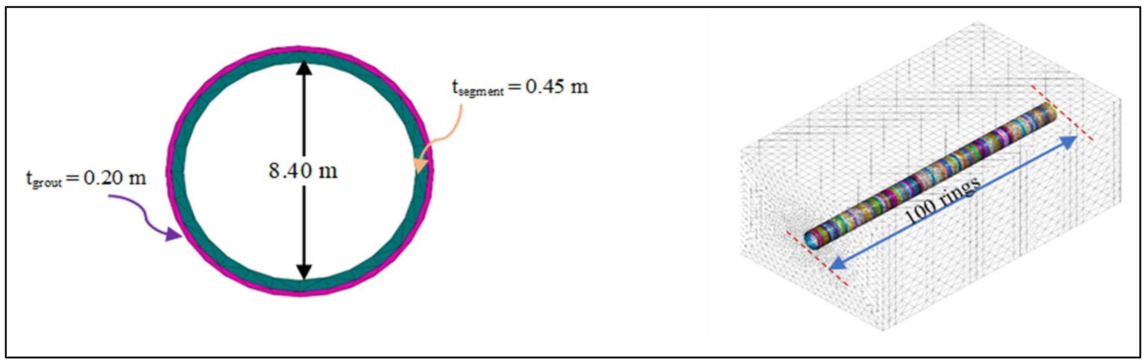
This research examines a deep-bored tunnel buried in rock with a lining thickness of 450 mm where the outer diameter is 9.30 m and the inner diameter is 8.40 m, as illustrated in Figure 5. The tunnel has a burial depth (H) of 25 m from the ground surface and a segment width of 1.5 m. The total model’s dimensions are 150 m × 90 m × 60 m in the x, y, and z axes and the tunnel is formed out of 100 rings. Solid components were selected for the isolation coating, pea gravel grout, tunnel, fault, and rock. To fill the shield machine’s tail void, the isolation coating or grout was estimated to be 200 mm thick. There are two main models: the first is made up of a single layer of rock with a fault, and the second one consists of two rock types, as shown in Figure 6. The behavior of the rock is characterized using the Mohr–Coulomb (MC) criteria. Table 1 enumerates the rock’s material attributes. Table 2 displays the model’s elastic characteristics, as well as the conventional grout materials that were employed.
The Midas/GTS-NX FE program can automatically constrain the model. There are x-direction constraints on the model’s nodal degree-of-freedom (DOF) vertical sides. The y-direction constraints apply to both the face and back of the model. The y- and x-directions confine the DOFs in the z-direction for the bottom nodes. The DOFs along the ground surface are unrestricted.
The mesh size for the rock layer is 4 m × 4 m and refined to 1 m × 1 m for the tunnel, grout, and isolation. The most important part in mesh generation is the node connection between adjacent elements so that hybrid meshes are formed by combining a pyramid and tetrahedron on the hexahedron base, as shown in Figure 7.
The direct integrating approach was used to perform a linear dynamic time-history analysis. This method includes an analysis of all time stages, and the number or time stage is proportional to the analysis time. The El Centro 1940 data from the Midas/GTS-NX library were used as dynamic excitation sources that were not parallel to the tunnel axis (Figure 8). The peak ground acceleration was 0.30 g. Additionally, we used a 10 s stimulation period with a 0.02 s time step, or 500 steps.
FE models were considered to check the tunnel’s stability under seismic loading, as shown in Figure 9. For the modeling of rock with a fault, the parametric study for the isolation material used in the model was split into two sections. The first section examines the effects of changes in the isolation material’s mechanical properties related to the shear modulus of the rock and the fault, as shown in Table 3, on the stresses induced by the tunnel. The second section investigates the impact of variations in the isolation width with respect to the fault width on the stresses and displacements created in the tunnel.
For the modeling of a sudden change in the rock from medium strong rock to medium weak rock, the impact of isolation material in a tunnel under seismic loading was examined in the longitudinal y-direction and perpendicular to the tunnel section (horizontal x-direction and vertical z-direction). This investigation’s mechanical properties of the isolation material depended on the previously indicated parametric analysis, as shown in Table 4.
4. Results and Discussion
Since tunnels are structures that resist movement in the transverse direction, this analysis focuses on the ultimate displacement of tunnels and the stresses that are created in that direction. For the modeling of rock with a fault, Table 5 compares the absolute stresses applied to the tunnel using ordinary grout vs. isolating it along the tunnel related to the mechanical properties of the faults and rock.
The isolation hypothesis related to the properties of the rock or the fault was implemented along the tunnel to determine the material’s properties suitable for isolation of the fault. As a result, from Models 1 and 2, as shown in Figure 10, two materials were employed to isolate the tunnel, one in the area in contact with the fault and the other in the area in contact with the rock, as it has been demonstrated that the insulating qualities of soil must be related to the local soil characteristics. The shear modulus of isolation concerning the rock and fault shear modulus was varied for Models 3 to 6. The effect of these changes, as shown in Figure 11, illustrates that the outcomes of this assumption were more tangible.
On the other hand, as illustrated in Figure 11, a comparison of the tunnel crown’s vertical displacement for Models 3 to 6 shows that the displacement is less when utilizing Giso./Gfault = 0.2% instead of Giso./Gfault = 0.4%.
When there is seismic isolation around the tunnel, the vertical movement of the fault rises by roughly 25%, as shown in Figure 12.
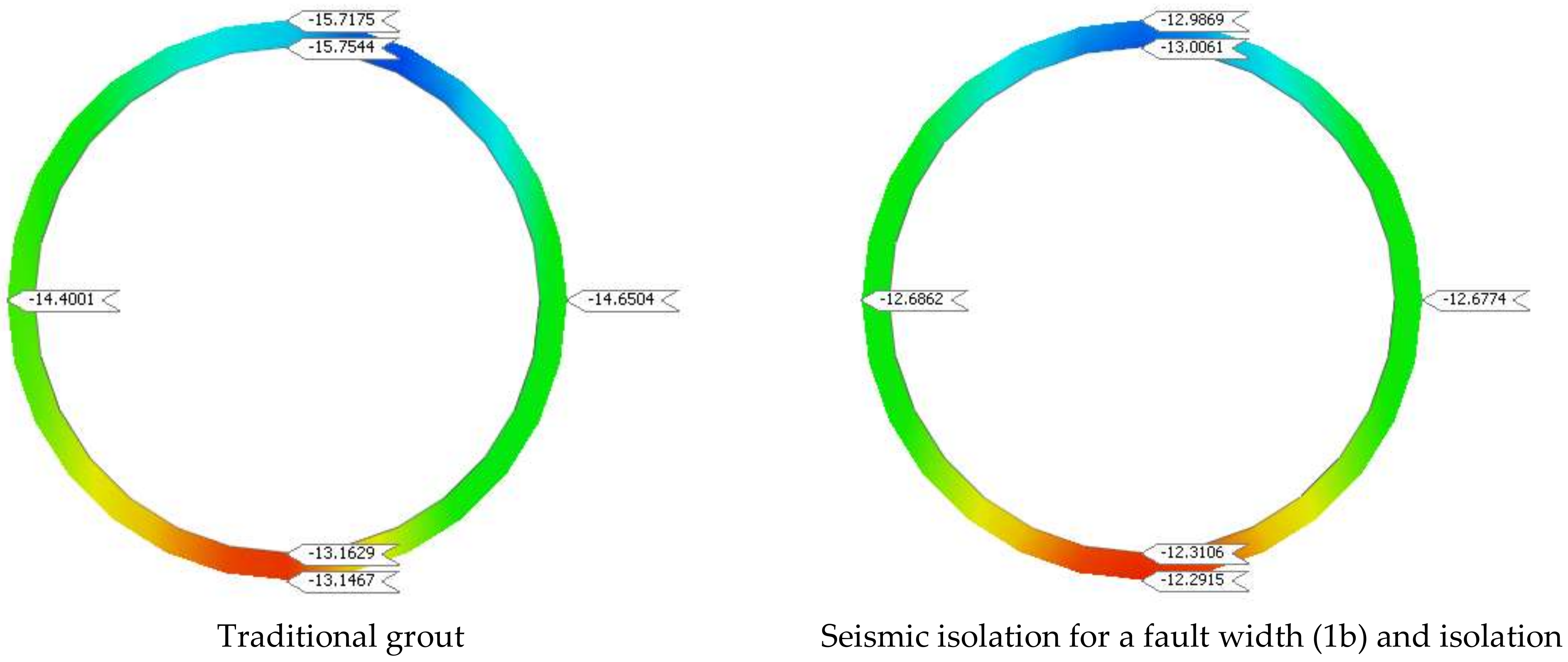
The subsequent section establishes the relationship between the fault’s width and the width of the insulation in the affected area, considering that Giso./Grock = 0.2% and Giso./Gfault = 0.4%. Models 7 to 10 explored the approximate relationship between the insulation’s width and the fault’s width, finding that it equaled 1, 2, 3, and 4 times its width. The impact of these changes on the stresses and displacement induced in the tunnel is shown in Table 6 and Figure 13 and Figure 14.
Although the effect of using insulation for a distance roughly equal to the width of the fault on the stresses in the footwall zone was greater than that using other lengths, it decreased the displacement induced in the tunnel, as shown in Figure 15.
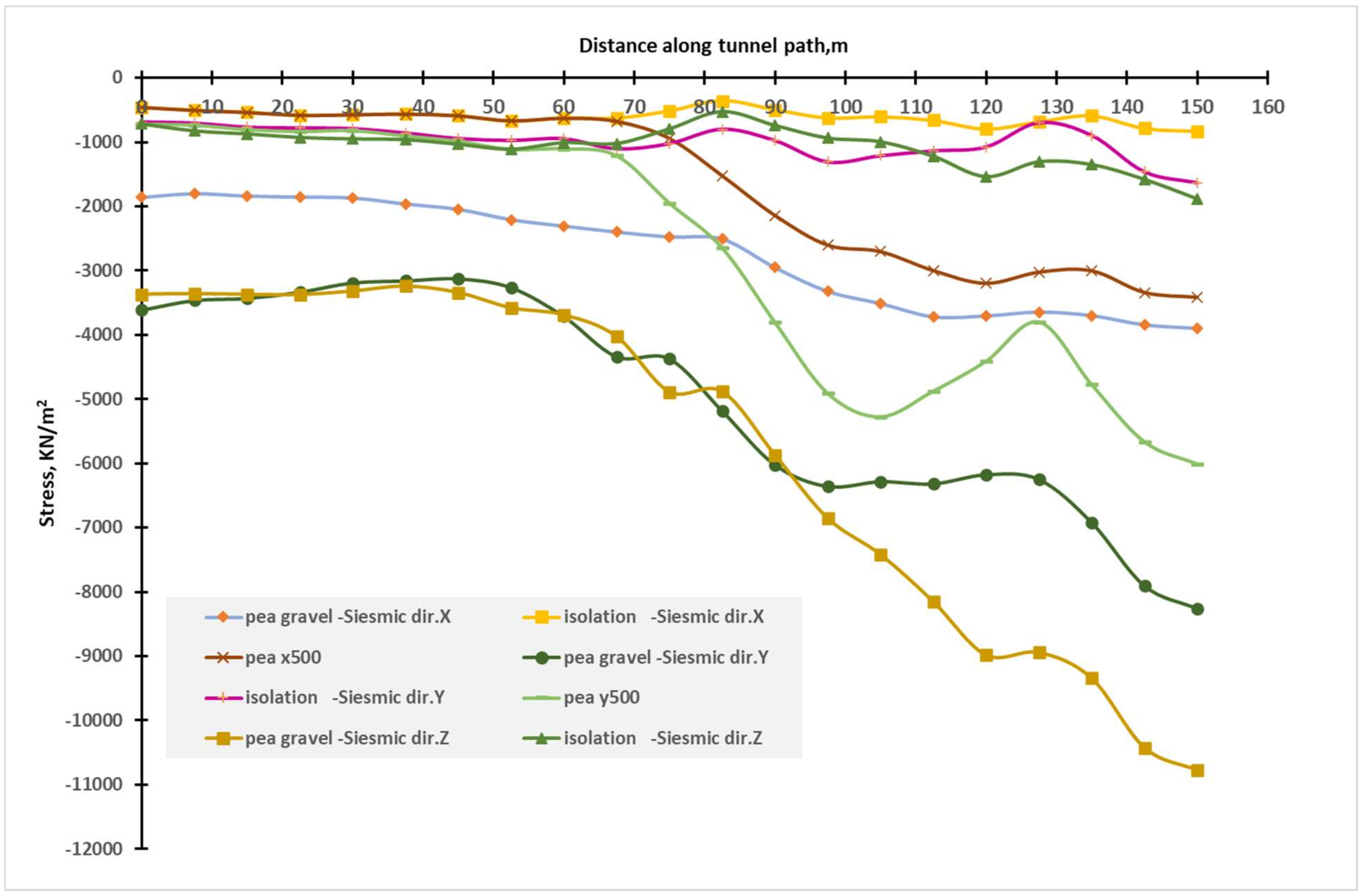
For a tunnel passing through a sudden change in rock, a comparison of the stresses when using traditional grout and using isolation with a shear modulus ratio of 0.2% (Grock) and Poisson’s ratio (0.2), as shown in Figure 16, is summarized in Table 7. This study indicates that using isolation redistributed the stresses in three directions and the percentage of decrease was approximately 11% to 31%.
5. Conclusions
As a result of this investigation, isolation material with Giso./Gfault = 0.2% to 0.4% is found to be more significant for stresses. In order to reduce parallel stresses to decrease vertical displacement, it is also recommended to choose isolation widths that are either equal to the fault width or double the fault width. The results of this study show that with a sudden change in rock, the effect of seismic isolation equates to the same decrease for the three directions of seismic waves.
The overall dynamic behavior of the tunnel and the generated stresses are generally improved when isolation is utilized for faults instead of typical grout or for sudden changes in rock without a fault. It is essential to look into the displacement drop that happens when the shear modulus of the isolation material decreases. When employing an actual design, construction and dynamic analysis must be integrated. This concept could help designers produce safe and affordable designs. Testing them with a small shear modulus or small unit weights is crucial to ensure that the isolation materials can sustain applied pressures without liquefying.
Attention should be paid to the comparison between the natural frequency of a tunnel and the frequency content of seismic motion to avoid the phenomenon of resonance. Combining construction results with dynamic results should be carried out in actual design. The tensile stresses resulting from dynamic behavior may be improved by the compression stresses caused by construction. This point can assist the designer in arriving at a safe and affordable design. It is preferable to use seismic isolation in a limited area when a sudden change in soil composition occurs, rather than along the tunnel path, and it is expected that a seismic response will occur.
Author Contributions
Conceptualization, A.E. and N.E.; methodology, A.E.; software, A.E.; validation, A.E. and N.E.; formal analysis, N.E.; investigation, A.E.; resources, A.E.; data curation, A.E.; writing—original draft preparation, N.E.; writing—review and editing, A.E.; visualization, A.E.; supervision, A.E.; funding acquisition, N.E. All authors have read and agreed to the published version of the manuscript.
Funding
This research received no external funding.
Data Availability Statement
Data are contained within the article.
Conflicts of Interest
The authors declare no conflict of interest.
References
- Zhu, X.M.; Liu, M. Numerical simulation of influences of fault angulation on tunnel longitudinal stability. J. Xuzhou Inst. Archit. Technol. 2007, 7, 17–19. [Google Scholar]
- Liu, H.; Song, H.W.; Tang, D.K. Numerical modeling of influence of fault spacengel on longitudinal stability of tunnel. J. Heilongjiang Inst. Sci. Technol. 2008, 18, 447–450. [Google Scholar]
- Jeon, S.; Kim, J.; Seo, Y.; Hong, C. Effect of a fault and weak plane on the stability of a tunnel in rock—A scaled model test and numerical analysis. Int. J. Rock Mech. Min. Sci. 2004, 41, 658–663. [Google Scholar] [CrossRef]
- Lee, F.H.; Hong, S.H.; Gu, Q.; Zhao, P. Application of large three-dimensional finite-element analyses to practical problems. Int. J. Geomech. 2011, 11, 529–539. [Google Scholar] [CrossRef]
- Meschke, G.; Nagel, F.; Stascheit, J. Computational simulation of mechanized tunneling as part of an integrated decision support platform. Int. J. Geomech. 2011, 11, 519–528. [Google Scholar] [CrossRef]
- Chen, S.L.; Abousleiman, Y.N.; Muraleetharan, K.K. Closed-form elastoplastic solution for the wellbore problem in strain hardening/softening rock formations. Int. J. Geomech. 2012, 12, 494–507. [Google Scholar] [CrossRef]
- Verma, A.K.; Deb, D. Numerical analysis of an interaction between hydraulic-powered support and surrounding rock strata. Int. J. Geomech. 2013, 13, 181–192. [Google Scholar] [CrossRef]
- Lu, A.; Zhang, N.; Zhang, X.; Lu, D.; Li, W. Analytic method of stress analysis for an orthotropic rock mass with an arbitrary-shaped tunnel. Int. J. Geomech. 2015, 15, 04014068. [Google Scholar] [CrossRef]
- Zareifard, M.R.; Fahimifar, A. Elastic–brittle–plastic analysis of circular deep underwater cavities in a Mohr-Coulomb rock mass considering seepage forces. Int. J. Geomech. 2015, 15, 04014077. [Google Scholar] [CrossRef]
- Yang, F.; Yang, J.S. Stability of shallow tunnel using rigid blocks and finite-element upper bound solutions. Int. J. Geomech. 2010, 10, 242–247. [Google Scholar] [CrossRef]
- Kumar, J.; Bhattacharya, P. Reducing the computational effort for performing linear optimization in the lower-bound finite elements limit analysis. Int. J. Geomech. 2011, 11, 406–412. [Google Scholar] [CrossRef]
- Duenser, C.; Thoeni, K.; Riederer, K.; Lindner, B.; Beer, G. New developments of the boundary element method for underground constructions. Int. J. Geomech. 2012, 12, 665–675. [Google Scholar] [CrossRef]
- Kumar, J.; Sahoo, J.P. Upper bound solution for pullout capacity of vertical anchors in sand using finite elements and limit analysis. Int. J. Geomech. 2012, 12, 333–337. [Google Scholar] [CrossRef]
- Kermani, E.; Qiu, T.; Li, T. Simulation of collapse of granular columns using the discrete element method. Int. J. Geomech. 2015, 15, 04015004. [Google Scholar] [CrossRef]
- Kim, Y.G.; Han, B.H.; Lee, S.B.; Kim, E.T. A case study of collapse and reinforcement for large span waterway tunnel at thrust fault zone. Tunn. Undergr. Space 2011, 21, 251–263. [Google Scholar]
- Zhao, K.; Janutolo, M.; Barla, G.; Chen, G. 3D simulation of TBM excavation in brittle rock associated with fault zones: The Brenner Exploratory Tunnel case. Eng. Geol. 2014, 181, 93–111. [Google Scholar] [CrossRef]
- Dalgıç, S. Tunneling in fault zones, Tuzla tunnel, Turkey. Tunn. Undergr. Space Technol. 2003, 18, 453–465. [Google Scholar] [CrossRef]
- Shrestha, P.K.; Panthi, K.K. Groundwater effect on faulted rock mass: An evaluation of Modi Khola pressure tunnel in the Nepal Himalaya. Rock Mech. Rock Eng. 2014, 47, 1021–1035. [Google Scholar] [CrossRef]
- Fraldi, M.; Guarracino, F. Limit analysis of collapse mechanisms in cavities and tunnels according to the Hoek–Brown failure criterion. Int. J. Rock Mech. Min. Sci. 2009, 46, 665–673. [Google Scholar] [CrossRef]
- Fraldi, M.; Guarracino, F. Analytical solutions for collapse mechanisms in tunnels with arbitrary cross sections. Int. J. Solids Struct. 2010, 47, 216–223. [Google Scholar] [CrossRef]
- Fraldi, M.; Guarracino, F. Evaluation of impending collapse in circular tunnels by analytical and numerical approaches. Tunn. Undergr. Space Technol. 2011, 26, 507–516. [Google Scholar] [CrossRef]
- Mollon, G.; Dias, D.; Soubra, A.H. Face stability analysis of circular tunnels driven by a pressurized shield. J. Geotech. Geoenvironmental Eng. 2010, 136, 215–229. [Google Scholar] [CrossRef]
- Huang, F.; Qin, C.B.; Li, S.C. Determination of minimum cover depth for shallow tunnel subjected to water pressure. J. Cent. South Univ. 2013, 20, 2307–2313. [Google Scholar] [CrossRef]
- Xiong, W.; Fan, W.; Peng, J.B.; Deng, L.S.; Yan, F.R. Numerical analysis of effect of normal fault activity on road mountain tunnel project. Chin. J. Rock Mech. Eng. 2010, 29, 2845–2852. [Google Scholar]
- Huang, S.; Si, T.; Chen, W. Finite element analyses of influence of fault on large-span tunnel surrounding rock stress. Chin. J. Rock Mech. Eng. 2006, 25, 3788–3793. [Google Scholar]
- Osman, A.S.; Mair, R.J.; Bolton, M.D. On the kinematics of 2D tunnel collapse in undrained clay. Geotechnique 2006, 56, 585–595. [Google Scholar] [CrossRef]
- Wang, Y.; Jing, H.; Su, H.; Xie, J. Effect of a fault fracture zone on the stability of tunnel-surrounding rock. Int. J. Geomech. 2017, 17, 04016135. [Google Scholar] [CrossRef]
- Dowding, C.H.; Rozan, A. Damage to rock tunnels from earthquake shaking. J. Geotech. Eng. Div. 1978, 104, 175–191. [Google Scholar] [CrossRef]
- ITA (International Tunneling and Underground Space Association). Tunnel Market Survey. 2016. Available online: https://www.tunnel-online.info/en/artikel/tunnel_Tunnel_Market_Survey_2016_3051818.html (accessed on 8 December 2019).
- Yu, H.T.; Chen, J.T.; Yuan, Y.; Zhao, X. Seismic damage of mountain tunnels during the 5.12 Wenchuan earthquake. J. Mt. Sci. 2016, 13, 1958–1972. [Google Scholar] [CrossRef]
- He, W.; Wu, Z.; Kojima, Y.; Asakura, T. Failure mechanism of deformed concrete tunnels subject to diagonally concentrated loads. Comput. Aided Civ. Infrastruct. Eng. 2009, 24, 416–431. [Google Scholar] [CrossRef]
- Loukidis, D.; Bouckovalas, G.D.; Papadimitriou, A.G. Analysis of fault rupture propagation through uniform soil cover. Soil Dyn. Earthq. Eng. 2009, 29, 1389–1404. [Google Scholar] [CrossRef]
- Anastasopoulos, I.; Gazetas, G. Foundation–structure systems over a rupturing normal fault: Part I. Observations after the Kocaeli 1999 earthquake. Bull. Earthq. Eng. 2007, 5, 253–275. [Google Scholar] [CrossRef]
- Zhong, Z.; Wang, Z.; Zhao, M.; Du, X. Structural damage assessment of mountain tunnels in fault fracture zone subjected to multiple strike-slip fault movement. Tunn. Undergr. Space Technol. 2020, 104, 103527. [Google Scholar] [CrossRef]
- Jaramillo, C.A. Impact of seismic design on tunnels in rock–Case histories. Undergr. Space 2017, 2, 106–114. [Google Scholar] [CrossRef]
- Yue, L.F.; Suppe, J.; Hung, J.H. Structural geology of a classic thrust belt earthquake: The 1999 Chi-Chi earthquake Taiwan (Mw = 7.6). J. Struct. Geol. 2005, 27, 2058–2083. [Google Scholar] [CrossRef]
- Wang, Z. A preliminary report on the Great Wenchuan Earthquake. Earthq. Eng. Eng. Vib. 2008, 7, 225–234. [Google Scholar] [CrossRef]
- Chen, Z.; Shi, C.; Li, T.; Yuan, Y. Damage characteristics and influence factors of mountain tunnels under strong earthquakes. Nat. Hazards 2012, 61, 387–401. [Google Scholar] [CrossRef]
- Lin, M.L.; Chung, C.F.; Jeng, F.S.; Yao, T.C. The deformation of overburden soil induced by thrust faulting and its impact on underground tunnels. Eng. Geol. 2007, 92, 110–132. [Google Scholar] [CrossRef]
- Durukal, E. Critical evaluation of strong motion in Kocaeli and Düzce (Turkey) earthquakes. Soil Dyn. Earthq. Eng. 2002, 22, 589–609. [Google Scholar] [CrossRef]
- Ma, C.; Lu, D.; Zhao, Y.; Wang, Z.; Du, X. Performance of an underground structure seismic mitigation system improved by frictional deformation absorbing braces. Structures 2022, 37, 1–16. [Google Scholar] [CrossRef]
- Wang, Z.; Gao, B.; Jiang, Y.; Yuan, S. Investigation and assessment on mountain tunnels and geotechnical damage after the Wenchuan earthquake. Sci. China Ser. Technol. Sci. 2009, 52, 546–558. [Google Scholar] [CrossRef]
- Yu, H.; Chen, J.; Bobet, A.; Yuan, Y. Damage observation and assessment of the Longxi tunnel during the Wenchuan earthquake. Tunn. Undergr. Space Technol. 2016, 54, 102–116. [Google Scholar] [CrossRef]
- Wang, W.L.; Wang, T.T.; Su, J.J.; Lin, C.H.; Seng, C.R.; Huang, T.H. Assessment of damage in mountain tunnels due to the Taiwan Chi-Chi Earthquake. Tunn. Undergr. Space Technol. 2001, 16, 133–150. [Google Scholar] [CrossRef]
- Li, T. Damage to mountain tunnels related to the Wenchuan earthquake and some suggestions for aseismic tunnel construction. Bull. Eng. Geol. Environ. 2012, 71, 297–308. [Google Scholar] [CrossRef]
- Kiani, M.; Akhlaghi, T.; Ghalandarzadeh, A. Experimental modeling of segmental shallow tunnels in alluvial affected by normal faults. Tunn. Undergr. Space Technol. 2016, 51, 108–119. [Google Scholar] [CrossRef]
- Moradi, M.; Rojhani, M.; Galandarzadeh, A.; Takada, S. Centrifuge modeling of buried continuous pipelines subjected to normal faulting. Earthq. Eng. Eng. Vib. 2013, 12, 155–164. [Google Scholar] [CrossRef]
- Cai, Q.P.; Peng, J.M.; Ng, C.W.; Shi, J.W.; Chen, X.X. Centrifuge and numerical modelling of tunnel intersected by normal fault rupture in sand. Comput. Geotech. 2019, 111, 137–146. [Google Scholar] [CrossRef]
- Tsinidis, G.; de Silva, F.; Anastasopoulos, I.; Bilotta, E.; Bobet, A.; Hashash, Y.M.; He, C.; Kampas, G.; Knappett, J.; Madabhushi, G.; et al. Seismic behaviour of tunnels: From experiments to analysis. Tunn. Undergr. Space Technol. 2020, 99, 103334. [Google Scholar] [CrossRef]
- Demirci, H.E.; Bhattacharya, S.; Karamitros, D.; Alexander, N. Experimental and numerical modelling of buried pipelines crossing reverse faults. Soil Dyn. Earthq. Eng. 2018, 114, 198–214. [Google Scholar] [CrossRef]
- Kiyomiya, O.; Nakamichi, M.; Yokota, H.; Shiraishi, S. New type flexible joint for the Osaka Port Yumeshima Tunnel Osamu Kiyomiya. In Proceedings of the Oceans’ 04 MTS/IEEE Techno-Ocean’04 (IEEE Cat. No. 04CH37600), Kobe, Japan, 9–12 November 2004; Volume 4, pp. 2086–2091. [Google Scholar]
- Russo, M.; Germani, G.; Amberg, W. Design and construction of large tunnel through active faults: A recent application. In Proceedings of the International Conference of Tunneling and Underground Space Use, Istanbul, Turkey, 16–18 October 2002; pp. 1–14. [Google Scholar]
- Hashash, Y.M.; Hook, J.J.; Schmidt, B.; John, I.; Yao, C. Seismic design and analysis of underground structures. Tunn. Undergr. Space Technol. 2001, 16, 247–293. [Google Scholar] [CrossRef]
- Douglas, W.S.; Warshaw, R. Design of seismic joint for San Francisco bay tunnel. J. Struct. Div. 1971, 97, 1129–1141. [Google Scholar] [CrossRef]
- Ertuğrul, N. Analysis of Seismic Behavior of Underground Structures: A Case Study on Bolu Tunnels. Master’s Thesis, Middle East Technical University, Ankara, Turkey, 2010. [Google Scholar]
- Kontoe, S.; Zdravkovic, L.; Potts, D.M.; Menkiti, C.O. Case study on seismic tunnel response. Can. Geotech. J. 2008, 45, 1743–1764. [Google Scholar] [CrossRef]
- Wang, T.T.; Kwok, O.L.A.; Jeng, F.S. Seismic response of tunnels revealed in two decades following the 1999 Chi-Chi earthquake (Mw 7.6) in Taiwan: A review. Eng. Geol. 2021, 287, 106090. [Google Scholar] [CrossRef]
- Zhang, P.Z.; Wen, X.Z.; Shen, Z.K.; Chen, J.H. Oblique, high-angle, listric-reverse faulting and associated development of strain: The Wenchuan earthquake of May 12, 2008, Sichuan, China. Annu. Rev. Earth Planet. Sci. 2010, 38, 353–382. [Google Scholar] [CrossRef]
- Zhang, L.F.; Li, R.H.; Liu, H.; Fang, Z.B.; Wang, H.B.; Yuan, Y.; Yu, H.T. A Review on Seismic Response and Aseismic Measures of Fault-crossing Tunnels. IOP Conf. Ser. Earth Environ. Sci. 2020, 570, 052046. [Google Scholar] [CrossRef]
- Ma, S.; Chen, W.; Zhao, W. Mechanical properties and associated seismic isolation effects of foamed concrete layer in rock tunnel. J. Rock Mech. Geotech. Eng. 2019, 11, 159–171. [Google Scholar] [CrossRef]
- Cui, G.; Ma, J.; Wang, D. A large 3D laboratory test on the deformation characteristic of shallow loess tunnel under different plastic states. Bull. Eng. Geol. Environ. 2021, 80, 7577–7590. [Google Scholar] [CrossRef]
- Shahidi, A.R.; Vafaeian, M. Analysis of longitudinal profile of the tunnels in the active faulted zone and designing the flexible lining (for Koohrang-III tunnel). Tunn. Undergr. Space Technol. 2005, 20, 213–221. [Google Scholar] [CrossRef]
- Zhang, J.; Wang, M.; Xi, C. Tunnel collapse mechanism and its control strategy in fault fracture zone. Shock Vib. 2021, 2021, 9988676. [Google Scholar] [CrossRef]
Figure 1.
Faulting in a tectonic earthquake.
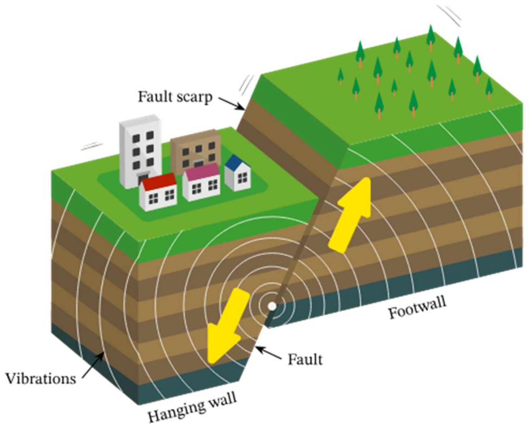
Figure 2.
Categorization of faults based on different criteria.
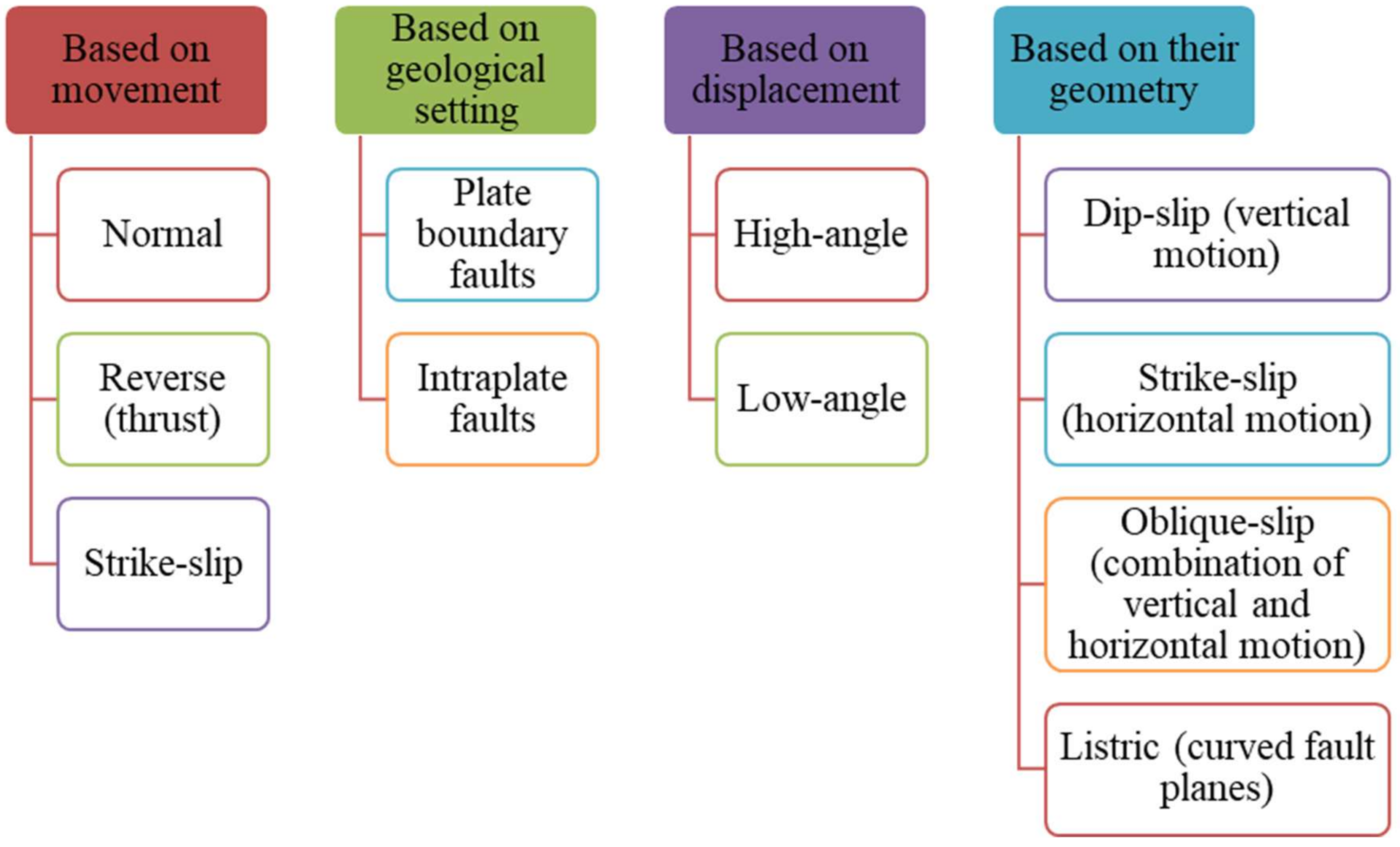
Figure 3.
Primary causes of faults.
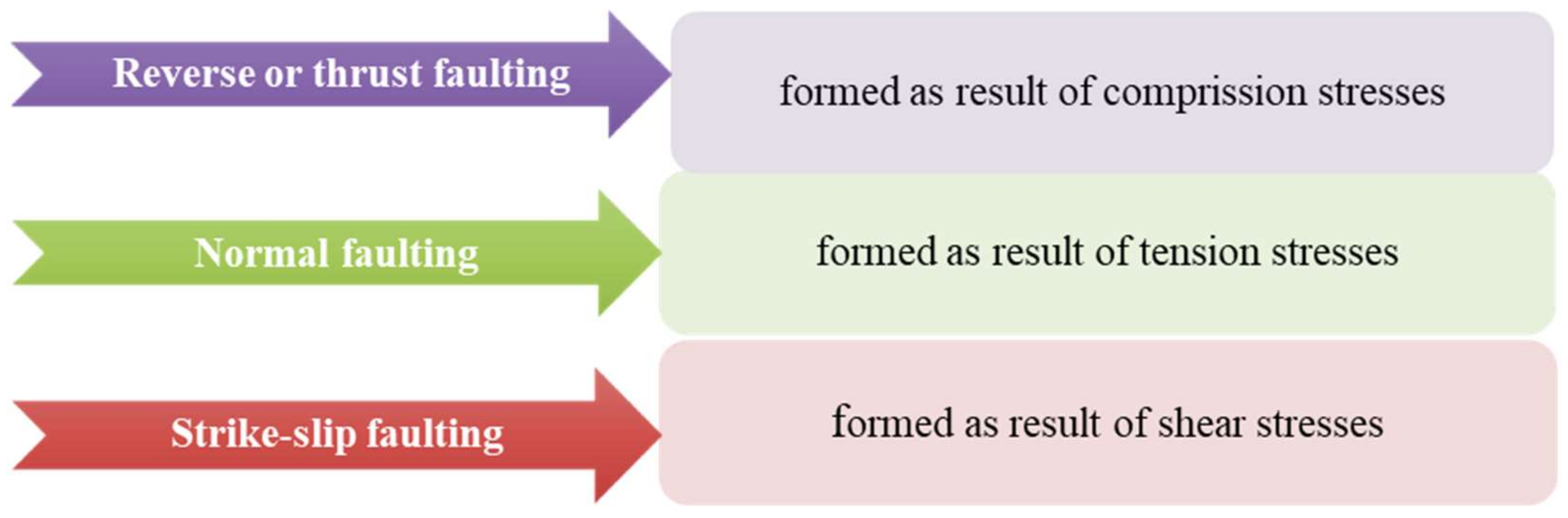
Figure 4.
Factors related to tunnel damage.
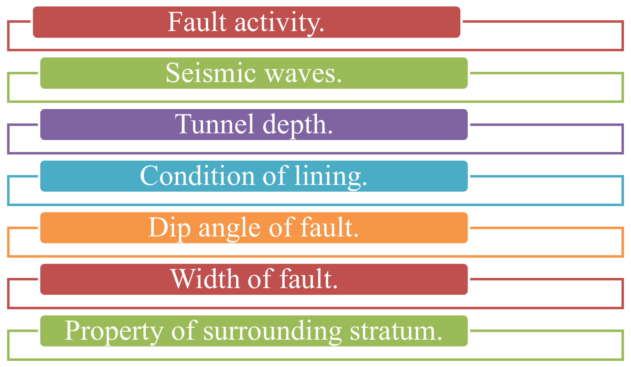
Figure 5.
Tunnel and grout dimensions.

Figure 6.
Two main models’ boundaries.
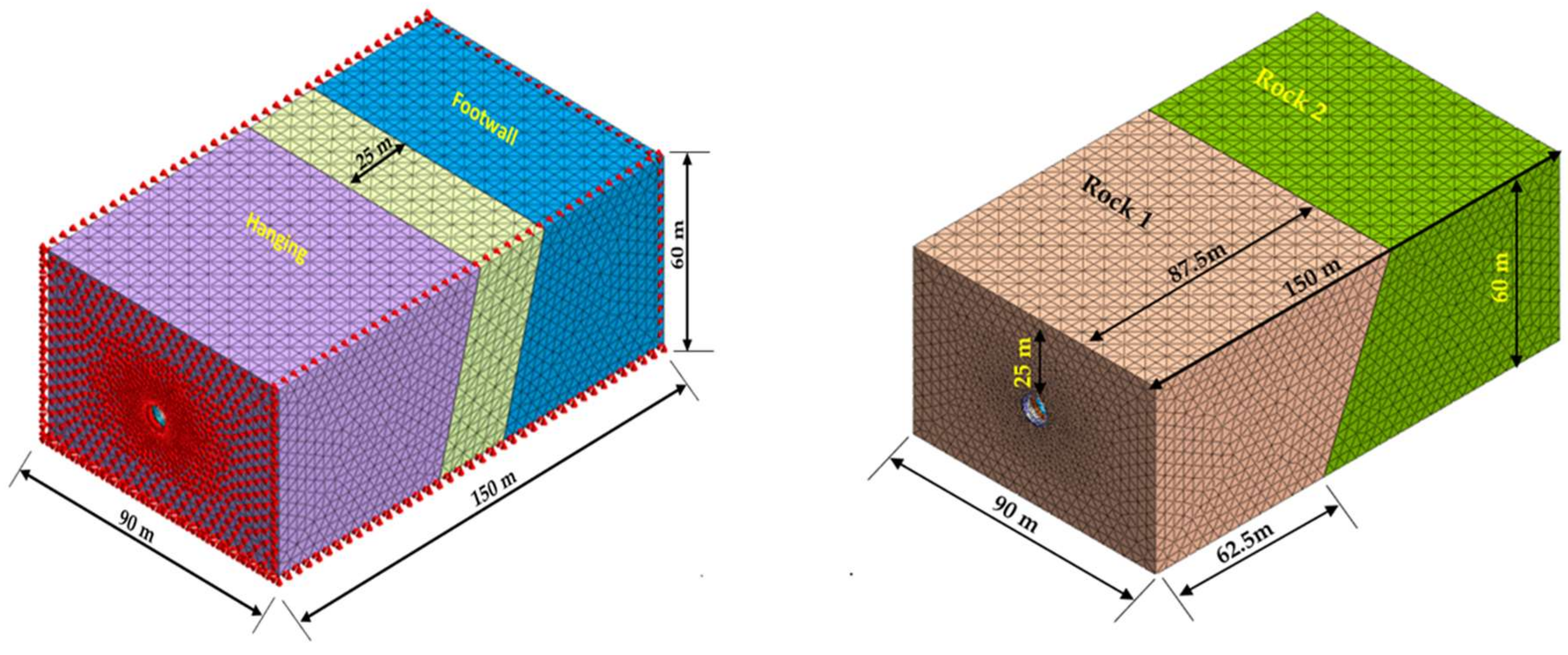
Figure 7.
Hybrid mesh shape.

Figure 8.
Acceleration time history.
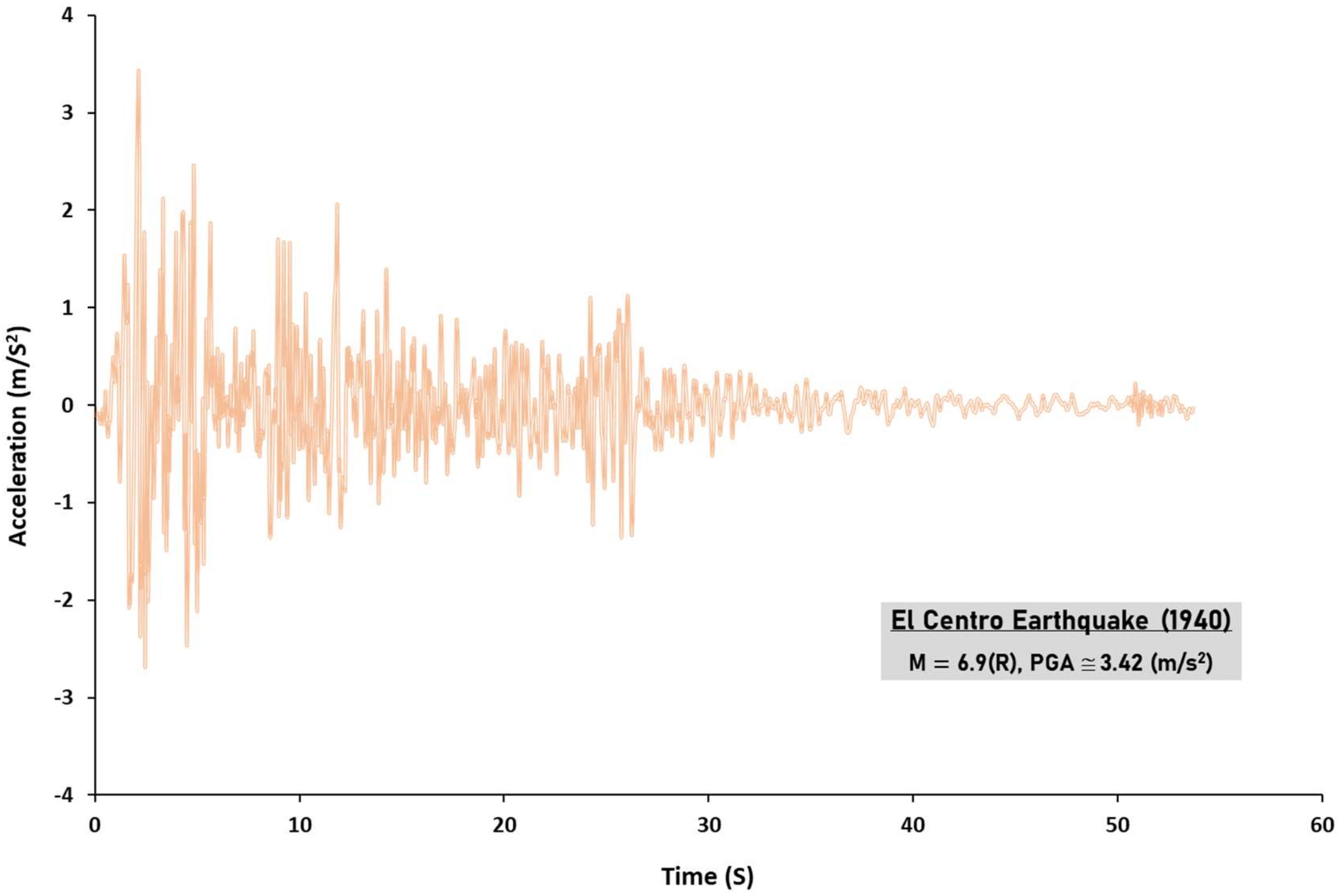
Figure 9.
Numerical modeling development flowchart.
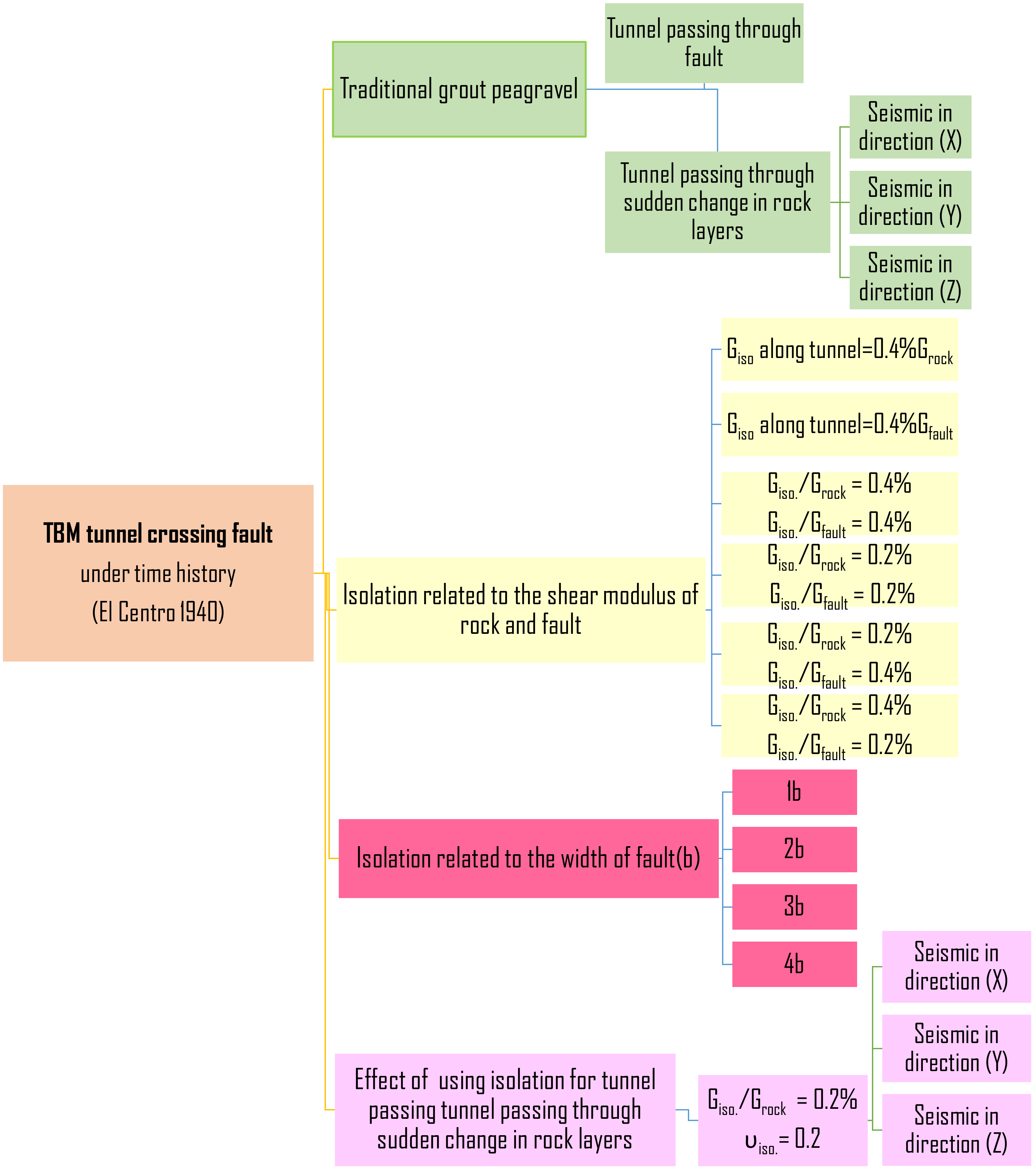
Figure 10.
Effect on transverse stresses due to shear modulus of isolation along the tunnel.

Figure 11.
Vertical displacement of tunnel crown due to shear modulus of isolation along the tunnel.
Figure 11.
Vertical displacement of tunnel crown due to shear modulus of isolation along the tunnel.
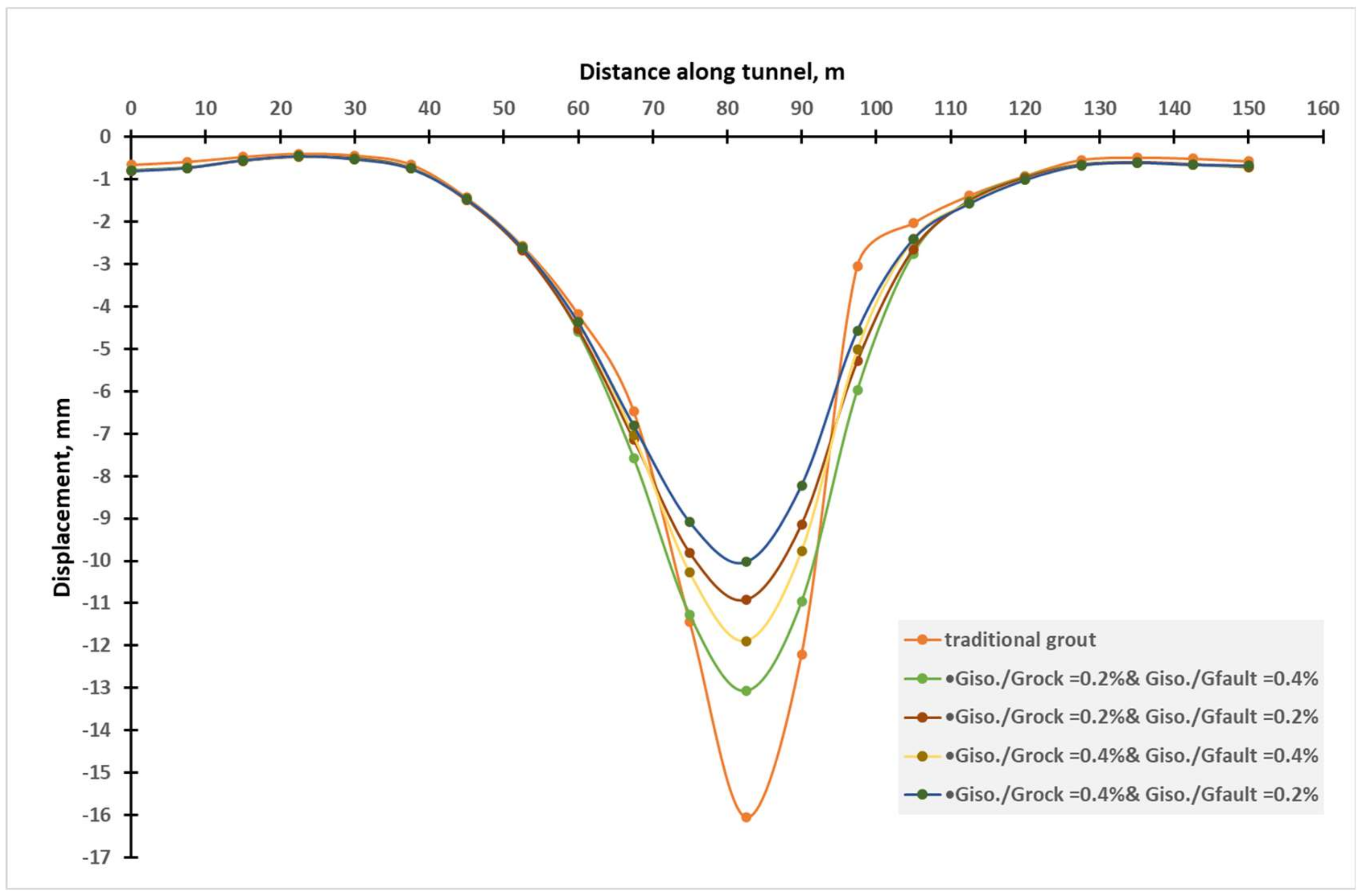
Figure 12.
Vertical displacement of the fault traditional grout vs. isolation.

Figure 13.
Effect on transverse stresses due to isolation related to fault width.
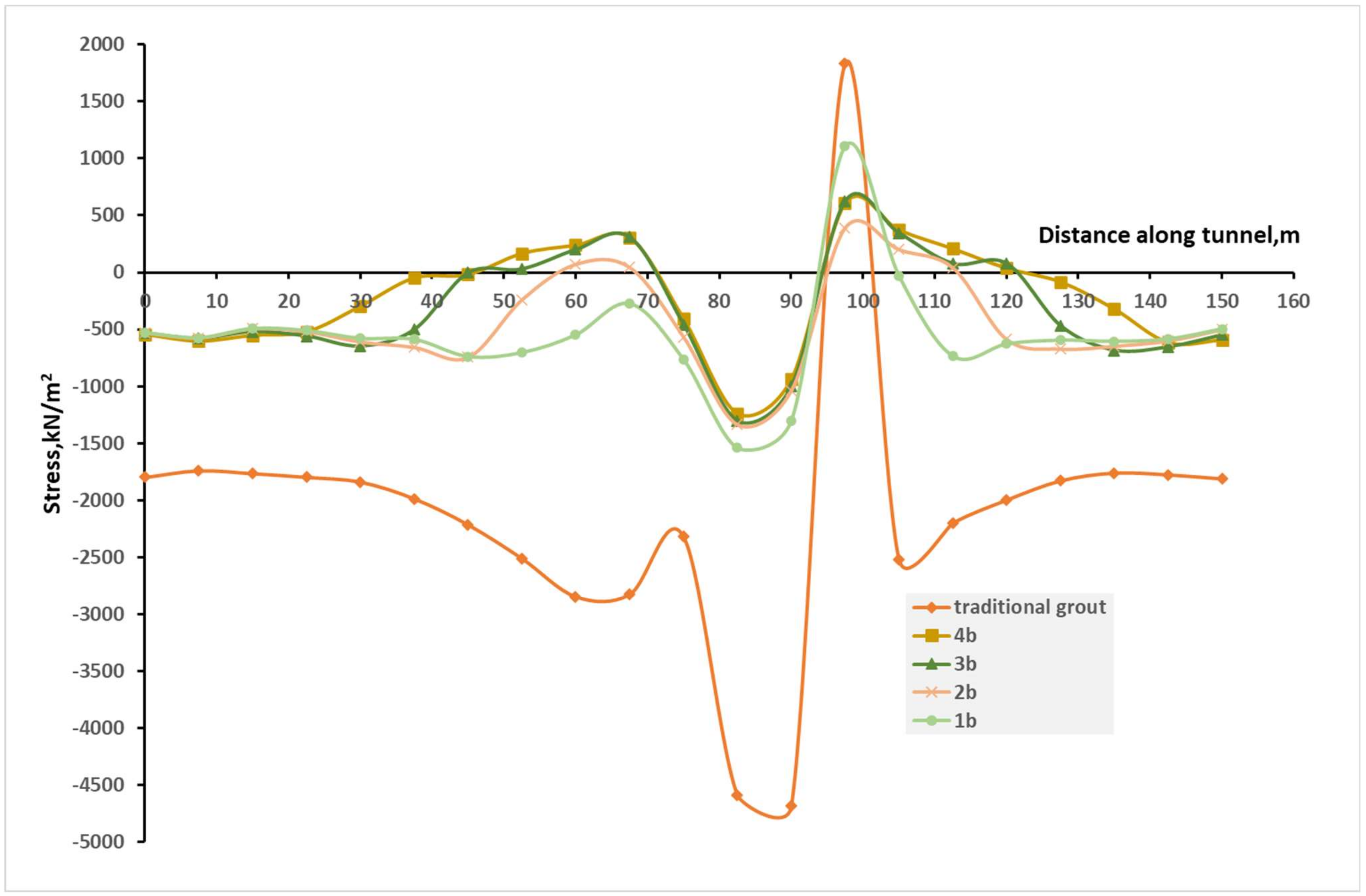
Figure 14.
Vertical displacement of tunnel crown due to isolation related to fault width.
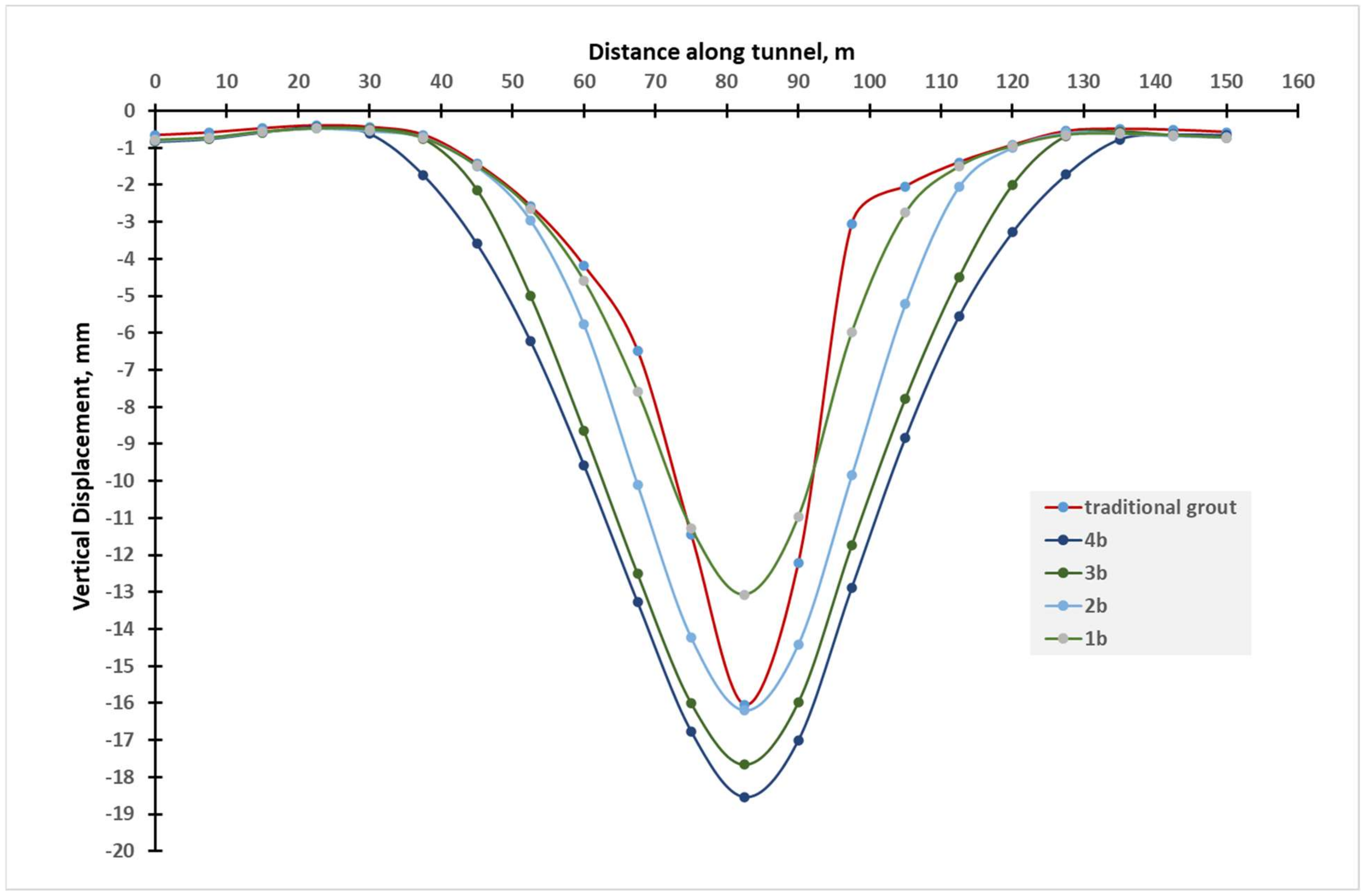
Figure 15.
Vertical displacement due to isolation related to fault width.

Figure 16.
Effect of isolation on tunnel transverse stresses in a sudden change in rock under three directions of seismic loading.
Figure 16.
Effect of isolation on tunnel transverse stresses in a sudden change in rock under three directions of seismic loading.

Table 1.
Characteristics of fault materials and rocks.
| Material | Modulus of Elasticity (E) (GPa) | Poisson’s Ratio (ν) | Unit Weight (γ) (kN/m3) | Cohesion (cu) (kN/m2) | Friction Angle (φ) |
|---|---|---|---|---|---|
| Rock 1 (medium-strong) | 6.00 | 0.30 | 23.00 | 700.00 | 39° |
| Rock 2 (medium-weak) | 1.00 | 0.30 | 23.00 | 200.00 | 30° |
| Fault | 0.2 | 0.30 | 21.00 | 150.00 | 23° |
Table 2.
Characteristics of concrete lining and traditional tail grout.
| Material | Modulus of Elasticity (E) (GPa) | Poisson’s Ratio (ν) | Unit Weight (γ) (kN/m3) |
|---|---|---|---|
| Concrete for segment | 30.00 | 0.20 | 25.00 |
| Grout for tunnel (pea gravel) | 1.00 | 0.30 | 23.00 |
Table 3.
Isolation material properties are based on changes in shear modulus.
| Material | Modulus of Elasticity (E) (kN/m2) | Poisson’s Ratio (ν) | Unit Weight (γ) (kN/m3) |
|---|---|---|---|
| Giso./Grock = 0.4% | 24,000 | 0.20 | 10.0 |
| Giso./Grock = 0.2% | 12,000 | 0.20 | 10.0 |
| Giso./Gfault = 0.4% | 800 | 0.20 | 8.0 |
| Giso./Gfault = 0.2% | 400 | 0.20 | 8.0 |
Table 4.
Characteristics of isolation material for two types of rock.
| Material | Modulus of Elasticity (E) (kN/m2) | Poisson’s Ratio (ν) | Unit Weight (γ) (kN/m3) |
|---|---|---|---|
| Isolation for Rock 1 | 12,000 | 0.20 | 11.50 |
| Isolation for Rock 2 | 2000 | 0.20 | 11.50 |
Table 5.
Effect of isolation instead of traditional grout related to shear modulus.
| Model No. | Grout/Isolation Description | Absolute Stresses | |
|---|---|---|---|
| At Rock | At Fault | ||
| Model 1 | Giso./Gfault = 0.4% along tunnel | (52:66)% | (89:185)% |
| Model 2 | Giso./Gfault = 0.4% along tunnel | (−1: −17)% | (19:36)% |
| Model 3 | Giso./Grock = 0.2% and Giso./Gfault = 0.4% | (19:33)% | (28:34)% |
| Model 4 | Giso./Grock = 0.2% and Giso./Gfault = 0.2% | (22:33)% | (18:25)% |
| Model 5 | Giso./Grock = 0.4% and Giso./Gfault = 0.4% | (39:52)% | (30:43)% |
| Model 6 | Giso./Grock = 0.4% and Giso./Gfault = 0.2% | (41:53)% | (19:24)% |
Change to a negative ratio means that the stresses become tension.
Table 6.
Effect of isolation instead of traditional grout related to fault width.
| Model No. | Isolation Width Related to Fault Width (b) | Absolute Stresses | ||
|---|---|---|---|---|
| At Rock | At Fault Hanging from the Wall to the Footwall | |||
| Giso./Grock = 0.2% | Giso./Gfault = 0.4% | Giso./Gfault = 0.4% | ||
| Model 7 | 1b | (19:34)% | ----- | (10:60)% |
| Model 8 | 2b | (28:34)% | (−2:9)% | (−2:21)% |
| Model 9 | 3b | (25:39)% | (−1:−7)% | (−11:34)% |
| Model 10 | 4b | (29:35)% | (−2:18)% | (−11:33)% |
Change to a negative ratio means the stresses become tension.
Table 7.
Effect of isolation instead of traditional grout in a sudden change in rock under three directions of seismic loading.
Table 7.
Effect of isolation instead of traditional grout in a sudden change in rock under three directions of seismic loading.
| Seismic Direction | Percentage of Absolute Stresses Using Isolation Compared to Pea Gravel |
|---|---|
| X | 14% to 31% |
| Y | 15% to 30% |
| Z | 11% to 31% |
Disclaimer/Publisher’s Note: The statements, opinions and data contained in all publications are solely those of the individual author(s) and contributor(s) and not of MDPI and/or the editor(s). MDPI and/or the editor(s) disclaim responsibility for any injury to people or property resulting from any ideas, methods, instructions or products referred to in the content. |
© 2024 by the authors. Licensee MDPI, Basel, Switzerland. This article is an open access article distributed under the terms and conditions of the Creative Commons Attribution (CC BY) license (https://creativecommons.org/licenses/by/4.0/).
Share and Cite
MDPI and ACS Style
Elgamal, A.; Elfaris, N. Enhancement Seismic Response of a Bored Tunnel Using Isolation for the Challenge of a Faulted Rock Crossing. Infrastructures 2024, 9, 66. https://doi.org/10.3390/infrastructures9040066
AMA Style
Elgamal A, Elfaris N. Enhancement Seismic Response of a Bored Tunnel Using Isolation for the Challenge of a Faulted Rock Crossing. Infrastructures. 2024; 9(4):66. https://doi.org/10.3390/infrastructures9040066
Chicago/Turabian StyleElgamal, Ahmed, and Nissreen Elfaris. 2024. "Enhancement Seismic Response of a Bored Tunnel Using Isolation for the Challenge of a Faulted Rock Crossing" Infrastructures 9, no. 4: 66. https://doi.org/10.3390/infrastructures9040066