Article

Texture Evolution in U-10Mo Nuclear Fuel Foils during Plasma Spray Coating with Zr

by
Shigehiro Takajo
1,*,†,
Kendall J. Hollis
2,
Dustin R. Cummins
2,
Eric L. Tegtmeier
2,
David E. Dombrowski
2 and
Sven C. Vogel
1,*
1
Materials Science and Technology Division, Los Alamos National Laboratory, Los Alamos, NM 87545, USA
2
Sigma Division, Los Alamos National Laboratory, Los Alamos, NM 87545, USA
*
Authors to whom correspondence should be addressed.
On leave from JFE Steel Corporation, Kurashiki 712, Japan.
Quantum Beam Sci. 2018, 2(2), 12; https://doi.org/10.3390/qubs2020012
Submission received: 21 April 2018 / Revised: 17 May 2018 / Accepted: 17 May 2018 / Published: 24 May 2018
(This article belongs to the Special Issue Strain, Stress and Texture Analysis with Quantum Beams)

Abstract

:
A uranium-molybdenum alloy clad in 6061 aluminum has the potential to lead to a wide application of low-enriched uranium fuels, replacing highly enriched uranium for research reactors. A Zr coating acts as a diffusion barrier between the fuel and the aluminum cladding. In this study, U-10Mo (mass %) was coated with Zr using a plasma spray technique recognized as a fast and economical coating method. Neutron time-of-flight diffraction was used to study the microstructure evolution by quantifying the phase fractions of involved phases as well as the texture evolution of U-10Mo and Zr during plasma spray coating with Zr. Quantitative texture analysis revealed that the texture was drastically changed for high coating temperatures, likely due to selective grain growth. Furthermore, the Zr coating showed a preferential orientation, which could be correlated with the initial texture of the uncoated U-10Mo. This could be explained by the epitaxial growth of the Zr on the U-10Mo substrate.

1. Introduction

The United States government is committed to further strengthening nuclear security and nonproliferation in order to reduce the threat of terrorists acquiring nuclear material. To meet this important mission, the U.S. Department of Energy/National Nuclear Security Agency’s Administration’s Office of Material Management and Minimization (M3) Reactor Conversion Program (CONVERT) minimizes the use of highly enriched uranium (HEU) in civilian applications by working with governments and facilities around the world to convert research reactors to the use of non-weapons-usable low-enriched uranium (LEU) fuels. Each reactor converted not only eliminates the need for HEU at civilian sites but also reduces the amount of HEU being manufactured, stored, and transported where it is at its most vulnerable. In instances where suitable LEU fuels do not exist for particular reactors to convert, the M3 Reactor Conversion Program contributes to the development of new LEU fuels.
Currently, the CONVERT M3 Reactor Conversion Program is developing a high-density, monolithic U-Mo fuel for the research reactor conversion, while at the same time establishing efficient and economic fabrication and manufacturing capabilities. The U-Mo fuel is required to show isotropic properties, such as isotropic thermal expansion, to prevent fuel voids in its application [1,2]. To address this requirement, 10 mass % molybdenum is alloyed to the uranium, which suppresses the orthorhombic α -U phase and stabilizes the body centered cubic (bcc) γ -U phase [3]. While the microstructure evolution of the fuel material is under research, and the physical properties [4,5,6,7] as well as the crystallographic phases [3,4,6,8], including the time-temperature-transformation (TTT) diagram [9,10], have been investigated by diffraction methods, few studies of microstructural changes, such as texture evolution, resulting from other fuel fabrication process steps are known. These may also cause anisotropy in material properties and therefore require attention.
Furthermore, U-Mo fuel foils will be clad in 6061 aluminum. In order to prevent interaction between the fuel meat and the cladding, a zirconium metal diffusion barrier will be applied to the fuel prior to cladding [1,11,12,13]. Hot roll bonding, electroplating, and plasma spraying [14] after cold rolling have been studied to apply the Zr layer on the U-10Mo (mass %)—referred to as U-10Mo in the following. However, only recently has the bulk microstructure evolution of the U-10Mo foil during spray-coating, which should be studied for a better understanding of the anisotropic behavior of the material, been investigated [15].
The objective of this study, therefore, is to understand the texture evolution in U-10Mo nuclear fuel foils during plasma spray coating with Zr by means of a detailed component analysis of the orientation distribution function (ODF) of the observed textures. While pole figures are frequently used to represent textures, quantitative analysis of the ODF, such as the determination of volume fractions of fibers and components, provides a much more complete picture of the microstructure evolution [16,17,18,19], as it allows for the prediction of metallurgical phenomena such as the recrystallization of γ phase. The ODF analysis for cubic crystal structures is very well known due to the extensive research on steels [20,21,22]. The results of this body of work is applied here to interpret textures in the much less investigated bcc U-10Mo. This report focuses on the texture data; other properties are provided and discussed in another manuscript [15]. Neutrons are an excellent probe for bulk texture measurements of uranium and its alloys, as it probes the entire sample volume, whereas X-ray or electron-based methods at best probe a few micrometers in these materials. Furthermore, full pattern diffraction data analysis utilizing tens of diffraction peaks, including overlapped ones, by Rietveld texture analysis allows for texture analysis of materials when no separate peaks are available to measure individual pole figures.

2. Experimental Methods

2.1. U-10Mo Preparation

An U-10Mo alloy was prepared from depleted uranium (0.2–0.3 wt % fraction of 235 U atoms). The hot-rolled sheet with the rolling temperature of 650 ° C was cold-rolled to a foil shape (0.33 mm thickness) with a reduction of 59% in the thickness direction. The foil was then annealed at 700 ° C for 1 h followed by an oil quenching to room temperature. According to the phase diagram [23], the phase of the U-10Mo is a single phase of γ around 550 ° C and higher, while the coexisting α -U phase appears below 550 ° C if kept for a sufficient time at the temperature. For example, the tip of the nose of the TTT curve for U-10Mo [1,24] is at 490 ° C and 5 h, where the decomposition of γ phase starts.

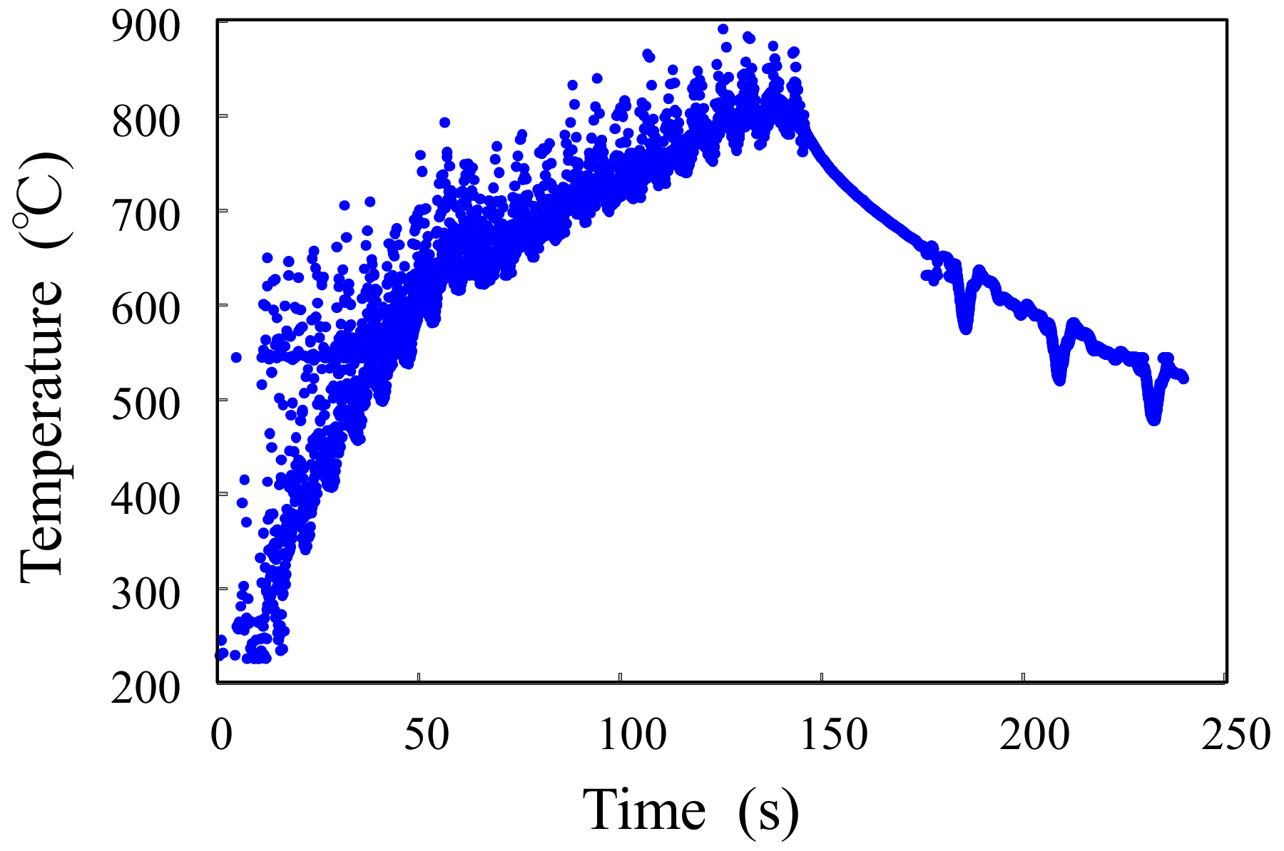
2.2. Plasma Spray Coating

A thin layer with a thickness between 23.8 and 34.0 µ m was coated on both sides of the annealed U-10Mo foils using the plasma spray method with different coating temperatures, as described in the previous paper [15]. Samples were coupons with the size of 102 × 19 × 0.33 mm 3 . The plasma torch used was a model SG-100 from Praxair/TAFA (Concord, NH, USA). The Zr powder had a particle size of 5–50 µ m and a purity of 99.2% and was purchased from ATI Specialty Alloys (Albany, OR, USA). He/Ar gas mix was flown around the sample to prevent oxidation. After 20 pre-heating torch passes for the purpose of surface cleaning, lasting for 60 s, a liquid phase Zr above its melting point of ∼1850 ° C was ejected towards the substrate in 16 torch passes for 48 s. Once the melt hit the substrate surface, the substrate was heated while the Zr was cooled. The coating passes were followed by 10 post-coat heating torch passes for 30 s. The surface temperature was measured with an infrared (IR) camera [15]. Figure 1 and Table 1 show a surface temperature at the center of the coated face of foil 151014 and the average surface temperature of both surfaces for the last torch pass, i.e., the maximum temperature observed for a given coating, respectively. The sample temperature increased until the torch was turned off. Various objects in the camera’s field of view caused the variation in temperature in Figure 1, while the U-Mo foil was generally the hottest object in the field of view. The temperature was not uniform between the five samples since different coating conditions controlled by plasma current and He/Ar gas flow rate were applied to each sample [15]. An uncoated sample, i.e., an annealed sample, was also prepared for comparison in this study.

2.3. Texture Measurement

Crystallographic textures of the Zr-coated U-10Mo foils as well as the uncoated U-10Mo were measured using time-of-flight neutron diffraction patterns obtained using the high-pressure preferred orientation time-of-flight diffractometer (HIPPO) [25,26] at the pulsed polychromatic spallation neutron source at the Los Alamos Neutron Science Center (LANSCE, Los Alamos, NM, USA) [27].The neutron diffraction method offers explicit advantages over X-ray diffraction in collecting the bulk information of both substrate (U-10Mo, ∼0.3 mm thickness) and thin coating (Zr, ∼30 µ m thickness) at the same time in a non-destructive way, especially when analyzing heavy elements, such as uranium, since X-rays can only penetrate a few micro-meters into the sample. The neutron diffraction data obtained using HIPPO provides a wide variety of material information including crystallographic textures, phase fractions, lattice parameters, and microstrain.
The 45 detector panels are arranged on five rings around the incident beam direction with 40 ° , 60 ° , 90 ° , 120 ° , and 144 ° diffraction angles. Data for texture analysis were collected using a robotic sample changer [28] with three different sample orientations by rotating the samples around the vertical axis by 0 ° , 67.5 ° , and 90 ° , and the data collection time was 2 h for each sample orientation owing to the comparably small sample volume. Samples were held with custom-made sheet sample holders, using set screws and felt to keep samples in the slit of an aluminum alloy rod mounted on standard HIPPO sample holders [28,29]. The neutron beam with a diameter of 10 mm was injected into the geometric center of the sample. The measurements at three different positions along the length of one foil (sample # 151008) resulted in equivalent data with each other and confirmed a homogeneous texture along the length of the sample. Although the sample volume where the neutron beam was diffracted was different among the three rotation angles due to the foil shape of the sample, texture analysis with the neutron method is fairly robust against this kind of systematic issue because a very large number of diffraction peaks is used to determine the ODF and the weak attenuation in a thin layer of depleted uranium. The 44 active detector panels of HIPPO and pulsed white neutron beams with a wide range of energy corresponding to the lattice spacing range between 0.6 and 3.0 Å allowed us to measure 1100 (hkl) diffraction peaks for γ -U and 3784 peaks for α -Zr simultaneously.
Refinement of the measured diffraction patterns was performed by Rietveld [30] analysis using the materials analysis using diffraction (MAUD) software [31], applying methods described by Wenk et al. [29]. The best possible fit for the measured diffraction data was calculated from the adjusted texture, lattice parameters, phase scales, thermal motion parameters, background, instrumental profile parameters, etc. The ODF was reconstructed in MAUD using extended Williams–Imhof–Matthies–Vinel (E-WIMV) analysis [32,33].

3. Results and Discussion
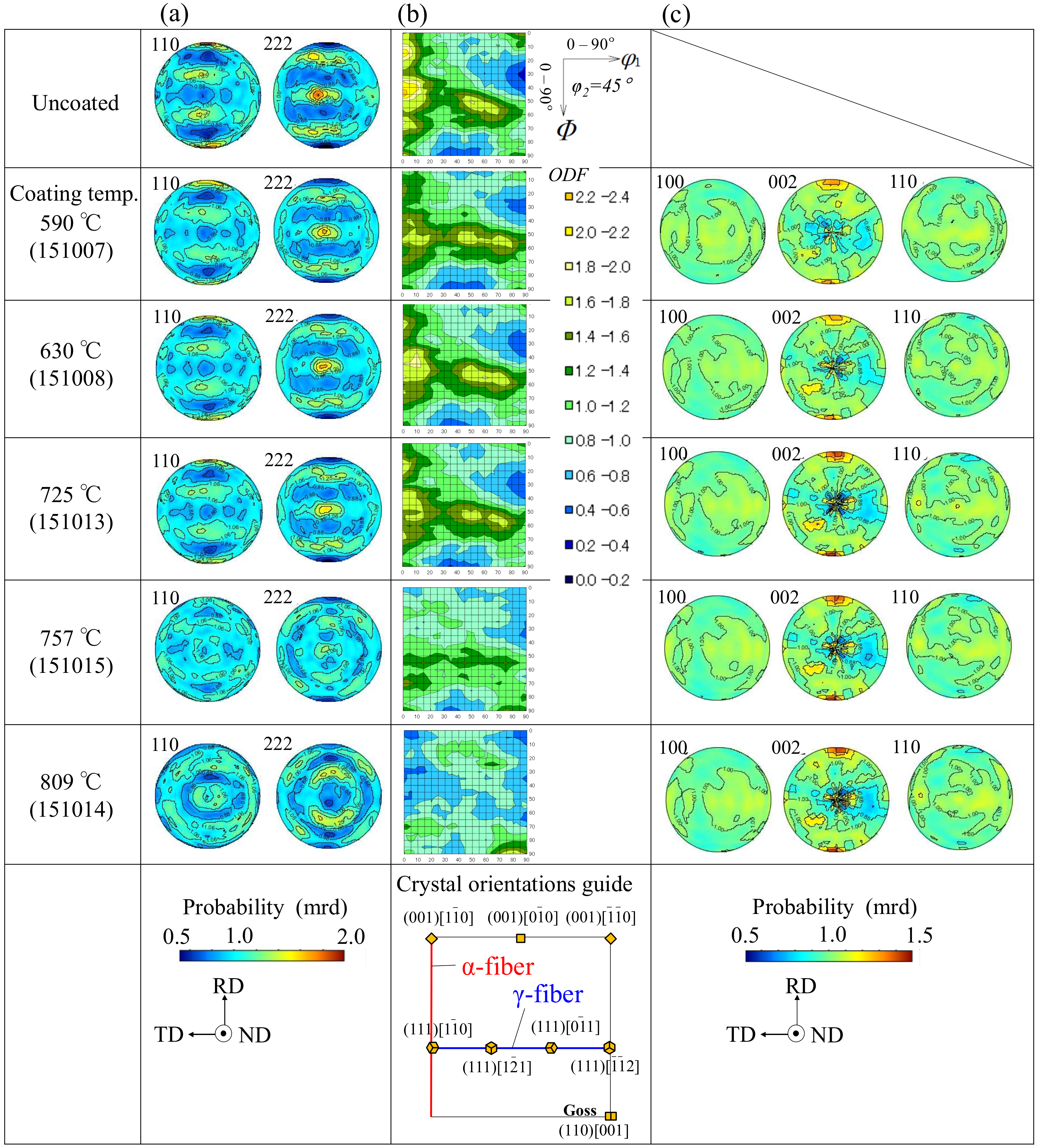
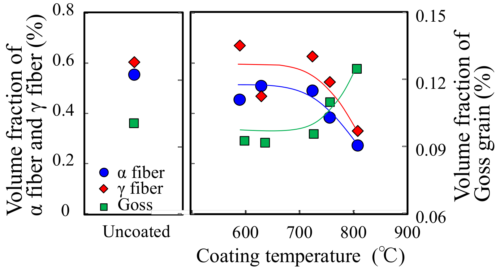
3.1. γ -U Texture

The Rietveld analysis of the neutron diffraction data revealed that the annealed U-10Mo foil used in this study showed a single phase of γ . The lattice parameters of the plasma spray coated samples were 3.492–3.505 Å (standard deviation for the eight measurement results σ = 0.010 Å) for a-axis of γ -U. The parameters are sensitive to residual strain, part of which is derived from thermal contraction difference between the coating and the substrate [2]. The amount of thermal contraction depends on the coating temperature, so the variation of the lattice parameters is due to differences in the heating pattern in the coating process.

3.1.1. Texture of the Uncoated Sample

Figure 2a,b show the pole figures for γ -U and the φ 2 = 45 ° ODF section of γ -U phase, respectively, of Zr-coated samples and the uncoated reference sample. In the uncoated sample, both α fiber and γ fiber [20] were developed, and the texture showed a maximum ODF intensity of no more than 2.4 multiples of random distribution (mrd). The texture with the α fiber and γ fiber can be observed in both deformed bcc steels and recrystallized bcc steels [21,22]. In the case of steels, the cold rolling texture with reductions around 60% shows ODF intensities of more than 5.0 mrd, which is stronger than that of the recrystallization texture. Brown et al. [2] suggested that a U-10Mo sample which was cold-rolled with a 50% reduction and annealed at 650 ° C also shows a recrystallization texture. Compared to the experiment in [2], manufacturing processes in this study consisted of a slightly higher cold rolling reduction and higher annealing temperature, which are more preferable conditions for recrystallization. Therefore, the U-10Mo used in this study is likely to undergo recrystallization during the annealing process before plasma spray coating.

3.1.2. Texture of the Coated Samples

In contrast, some of the coated samples showed different ODF intensities in α fiber and γ fiber. Figure 3 shows the effect of coating temperature on volume fraction of α fiber, γ fiber, and Goss orientation with a tolerance of integration angle of 2.5 ° . It should be noted that the α fiber components shown in the other φ 2 sections were not counted. As the coating temperature increased, the α fiber and γ fiber volume fractions showed a decreasing tendency until 725 ° C, the temperature that the samples had experienced in the annealing process before coating, but a sudden decrease at 757 ° C. At 757 ° C, the Goss component occurred and increased its volume fraction to 0.125% at 809 ° C.
The metallurgical phenomena that lead to a texture change during a heat treatment can be categorized into phase transformations, grain growth, and recrystallization. Phase transformation textures can be excluded here as the only phase transformation relevant here would be the decomposition to α -U after prolonged holding at temperatures below 590 ° C. This decomposition was not observed.
Recrystallization in general changes the texture drastically. Two kinds of recrystallization, namely primary and secondary recrystallization, are distinguished in the literature [34,35]. For primary recrystallization to occur, a certain amount of stored energy, which is a function of dislocation density, i.e., plastic deformation, is required. In the case of cold-rolled bcc steel, reduction of about 40% led to primary recrystallization [36], whereas small deformation, such as 3% temper rolling, was unlikely to cause primary recrystallization [37]. Since the material characterized here was annealed after the rolling reduction, it did not experience large plastic deformation just before the coating process. Therefore, primary recrystallization is not possible as a cause for the texture in the Zr-coated samples. On the other hand, the driving force of secondary recrystallization is grain boundary energy, which is typically much smaller than the stored energy that is the driving force of the primary recrystallization. Therefore, in general, the secondary recrystallization requires a much higher temperature or a longer dwell time than primary recrystallization. Furthermore, secondary recrystallization involves abnormally large grains, which could not be observed in the optical microscopy of this U-10Mo. Therefore, the secondary recrystallization was also not likely responsible for the drastic texture change of γ -U during the plasma spray coating, suggesting that the last possibility of grains growth was responsible for it.
The preferential Goss texture evolution during grain growth has been reported in bcc steel, where a small amount of plastic deformation, such as 3% temper rolling [38], introduced in the material led to a strain-induced boundary migration [39,40] during the following annealing process. According to Murakami et al. [41], the Goss grains received less strain than the other grains during the plastic deformation, which would be a preferable condition for the Goss grains to grow consuming other grains such as γ fiber grains [38]. The U-10Mo sample before plasma spray coating could receive a slight strain during the oil quenching in the annealing process because of an inhomogeneous temperature distribution in the sample. Assuming an oil temperature of 20 ° C, the strain between surface and centerline at the annealing temperature of 700 ° C can be estimated to be 1.0% by 680 ° C × α U 10 M o , where α U 10 M o (=1.49 × 10 5 /K) is the thermal expansion coefficient of U-10Mo, which is the averaged data of thermal expansion coefficients at 100, 200, 300, 400, 500, 600, and 700 ° C [42]. A deformation of 1.0% is sufficiently large for the plastic deformation to be introduced in the U-10Mo. Therefore, the small plastic strain from the quenching can explain the growth of the Goss component during the coating process.
To investigate if the observed texture changes are indeed caused by grain growth, Figure 4 shows the optical micrographs of samples 151007 and 151014, which were coated at 590 ° C and 809 ° C, respectively. Both samples showed equiaxed grains, suggesting a recrystallized microstructure, in agreement with our texture analysis, and the grains were coarser near the coating surface than in the center. The average grain size at locations ∼15 µ m from the surface was determined to be 35 µ m ( σ = 12.8 µ m) for sample 151007/590 ° C and 51 µ m ( σ = 17.3 µ m) for sample 151014/809 ° C, while that along the center-line was 33 µ m ( σ = 15.4 µ m) and 40 µ m ( σ = 16.1 µ m), respectively. Therefore, the average grain size in the center regions for the two samples from the lowest and highest coating conditions was the same within error bars. For the surface regions exposed to the plasma spraying, the average grain size for the lowest coating temperature also agreed with the grain size at the center line. Contrarily, for the grain size for the sample exposed to the maximum coating temperature an increase of 27.5% relative to the center line grain size was observed. This supports the fact that the grain growth occurred in the high-temperature coating process. Furthermore, Goss grains are reported to be more developed near the surface layer of the thickness in annealed bcc steel [43]. If this is the case with the U-10Mo, the coarse grains of γ -uranium near the surface in the samples Zr-coated at the temperature above 725 ° C would show the Goss orientations. A detailed local, rather than bulk, texture analysis using the scanning electron microscope-electron backscatter diffraction (SEM-EBSD) method will be reported in a forthcoming publication.

3.2. α -Zr Texture

The Rietveld analysis revealed that all of the Zr layers showed a crystalline single phase of α -Zr. The lattice parameters of the plasma spray coated samples were 3.312–3.326 Å ( σ = 0.002 Å) and 5.275–5.298 Å ( σ = 0.003 Å) for a-axis and c-axis of α -Zr, respectively. As addressed in the previous study [15], the variation is due to different amounts of atomic inclusions, typically oxygen, in combination with residual strain from the constrained cooling on the substrate. Pole figures for α -Zr of plasma-sprayed samples are shown in Figure 2c. Like the γ -U, the rolling direction of the substrate is in the 12 o’clock direction of the pole figure, the transverse to the rolling direction is the 9 o’clock direction, and the normal to the sample face is in the center of the pole figure. The scale is in multiples of a random distribution. A weak rolling direction (RD)// 002 texture component was developed in every sample. The ODF was analyzed for one sample with different sample orientations during the analysis so that the RD was moved from 12 o’clock to the center or to 9 o’clock of the pole figures, and the maxima observed in the (002) pole figures changed their location consistently with RD, thus proving that this comparably weak preferred orientation is in fact not an artefact.
The mechanism of the RD// 002 texture of the Zr coating is unlikely to be explained solely by solidification during the coating, which was performed under isotropic conditions along the in-plane direction. Conventional steel research has shown that a highly oriented texture to the normal direction can be developed after a casting [44] or high-temperature annealing [45], and the inclusions such as TiN or a lower surface energy of the steel might be responsible for the texture. However, the texture development to the rolling direction, as observed in the plasma coated Zr, has not been reported.
Since the coating for itself was unlikely to develop the RD// 002 texture of the α -Zr, the anisotropic texture of the substrate could influence the observed preferred orientation of the Zr coating. Specifically, the liquid Zr solidified as bcc β -Zr could be oriented with the γ -U substrate following transformation to α -Zr following the Burgers orientation relationship [46]. In what follows, the Burgers orientation relationship ( { 110 } b c c // { 0001 } h c p , 1 ¯ 1 ¯ 1 b c c // 11 2 ¯ 0 h c p ) was assumed to be satisfied between the β -Zr and α -Zr. This means that the β -Zr was assumed to show an RD// 110 b c c texture.
It is widely acknowledged that a lattice matched interface exists between two neighboring grains with different crystallographic phases that satisfy a specific crystallographic orientation relationship. To investigate the possible crystallographic relationship between the β -Zr and the γ -U, the lattice misfit values between lattices of coating ( β -Zr) and substrate ( γ -U) in various specific orientation directions were calculated and summarized in Table 2. In the calculation, the 110 and 200 directions were only considered for the γ -U since they were the dominant in-plane directions of samples 151007, 151008, and 151013 and samples 151014 and 151015, respectively. The lattice paramter at 1135 ° C (just below the melting point of U-10Mo) of 3.630 Å was used for the a-axis of β -Zr, which was estimated using a lattice parameter at 850 ° C [47] and a coefficient of thermal expansion of 9.7 × 10 6 /K [48]. This lattice parameter is close to the experimentally obtained lattice parameter of 3.627 Å for Zr-2.5Nb at 1050 ° C [49]. Furthermore, the lattice parameter of the a-axis for the γ -U at 1135 ° C was estimated to be 3.538 Å using the room temperature lattice parameter and a coefficient of thermal expansion of 11.8 × 10 6 /K [2]. The misfit Δ k in the direction of k at 1135 ° C was calculated from the following equation.
Δ k = | m a Z r k n a U 10 M o k | / n a U 10 M o k .
Here, a Z r k and a U 10 M o k are the minimum lattice distances in the direction of k of β -Zr and γ -U, respectively. The natural numbers m and n were chosen so that n/m is equal to 0.5, 1, 2, or 3. Both n/m equal to 1 and Δ k equal to 0 are satisfied when the two lattices show a perfect one-to-one correspondence.
It turned out that the textures developed in the coating and substrate, i.e., the RD// 110 texture of β -Zr and the RD// 110 texture of γ -U, produced a low lattice misfit of 2.6% in the RD compared to the misfit of 3.9% observed in the epitaxially grown TiN on an SUS304 stainless steel, which was coated by an ion plating HCD method [50]. As reported in the previous study [51], the crystal orientation could be determined so as to lower the misfit and the lattice distortion energy during an epitaxial growth. Therefore, it is suggested that the Zr grew epitaxially on the U-10Mo substrate.
To investigate the possibility of an epitaxial growth of the Zr on the substrate after the Goss texture with RD// 100 developed in the U-10Mo during plasma coating, the misfit between the 110 of the β -Zr and 100 of the γ -U was investigated. The minimum misfit turned out to be comparably large (27.4%), suggesting that the Zr crystal was not able to grow epitaxially from the 100 -oriented U. Therefore, the β -Zr coating would start to grow epitaxially from the RD// 110 oriented γ -U in the early stage of coating at the relatively low temperature of the substrate. Once the β -Zr texture was developed in the interface to the γ -U, the following accumulating coating remained the same texture because of the epitaxial growth. During this accumulating stage, the substrate temperature increased and the further grain growth of the γ -U occurred in some conditions with higher coating temperature, resulting in the texture change of the substrate. On the other hand, the β -Zr transformed to the α -Zr in its cooling process, resulting in the RD// 001 texture due to the Burgers orientation relationship.

4. Conclusions

In this work, we investigated the texture evolution in U-10Mo nuclear fuel foils during plasma spray coating with Zr using a time-of-flight neutron diffraction method. The γ -U of U-10Mo before plasma spray coating showed a weak α fiber and γ fiber texture with a maximum ODF intensity of 2.4 in the φ 2 = 45 ° ODF section. These fiber components decreased after the plasma spray coating with increasing maximum temperature during the coating, and a Goss texture developed with coating temperatures above 725 ° C. The α -Zr in every coated U-10Mo sample showed an RD// 002 texture. This preferential α -Zr texture developed possibly due to the following: (i) Zr was crystallized on the U-10Mo substrate in a β phase, satisfying the lattice matching between 110 of β -Zr and 110 of γ -U; (ii) during cooling of the coating, the β -Zr transformed to the α -Zr with satisfying the Burgers orientation relationship, resulting in the RD// 001 texture.

Author Contributions

Conceptualization, S.T., K.J.H. and S.C.V.; Methodology, S.T., K.J.H. and S.C.V.; Formal Analysis, S.T., K.J.H., E.L.T. and S.C.V.; Investigation, S.T., K.J.H., D.R.C., E.L.T. and S.C.V.; Resources, K.J.H. and D.E.D.; Data Curation, S.T., K.J.H. and S.C.V.; Writing—Original Draft Preparation, S.T.; Writing—Review & Editing, K.J.H., D.R.C. and S.C.V.; Visualization, S.T.; Supervision, K.J.H. and S.C.V.; Project Administration, K.J.H. and S.C.V.; Funding Acquisition, K.J.H. and S.C.V.

Funding

This research was funded by the U.S. Department of Energy/National Nuclear Security Administration’s M3 Reactor Conversion Program. Los Alamos National Laboratory, anaffirmative action equal opportunity employer, is operated by Los Alamos National Security, LLC for DOE/NNSA under contract DE-AC52-06NA25396.

Acknowledgments

S.T. gratefully acknowledges support from JFE Steel Corporation for his PhD thesis research at LANL.

Conflicts of Interest

The authors declare no conflict of interest.

References

  1. Meyer, M.K.; Hofman, G.L.; Hayes, S.L.; Clark, C.R.; Wiencek, T.C.; Snelgrove, J.L.; Strain, R.V.; Kim, K.H. Low-temperature irradiation behavior of uraniume molybdenum alloy dispersion fuel. J. Nucl. Mater. 2002, 304, 221–236. [Google Scholar] [CrossRef]
  2. Brown, D.W.; Okuniewski, M.A.; Sisneros, T.A.; Clausen, B.; Moore, G.A.; Balogh, L. Neutron diffraction measurement of residual stresses, dislocation density and texture in Zr-bonded U-10Mo mini fuel foils and plates. J. Nucl. Mater. 2016, 482, 63–74. [Google Scholar] [CrossRef]
  3. Sinha, V.P.; Hegde, P.V.; Prasad, G.J.; Dey, G.K.; Kamath, H.S. Phase transformation of metastable cubic γ-phase in U–Mo alloys. J. Alloys Compd. 2010, 506, 253–262. [Google Scholar] [CrossRef]
  4. Bostrom, W.A.; Haltman, E.K. The metastable gamma phase in uranium base molybdenum alloys. Adv. Nucl. Eng. 1957, 2, 184–193. [Google Scholar]
  5. Kim, K.H.; Lee, D.B.; Kim, C.K.; Hofman, G.L.; Paik, K.W. Thermal compatibility of centrifugally atomized U–Mo powders with aluminium in a dispersion fuel. Nucl. Eng. Des. 1997, 178, 111–117. [Google Scholar] [CrossRef]
  6. Burkes, D.E.; Papesch, C.A.; Maddison, A.P.; Hartmann, T.; Rice, F.J. Thermo-physical properties of DU–10 wt.% Mo alloys. J. Nucl. Mater. 2010, 403, 160–166. [Google Scholar] [CrossRef]
  7. Hengstler, R.M.; Beck, L.; Breitkreutz, H.; Jarousse, C.; Jungwirth, R.; Petry, W.; Schmid, W.; Schneider, J.; Wieschalla, N. Physical properties of monolithic U8 wt.%–Mo. J. Nucl. Mater. 2010, 402, 74–80. [Google Scholar] [CrossRef]
  8. Seong, B.S.; Lee, C.H.; Lee, J.S.; Shim, H.S.; Lee, J.H.; Kim, K.H.; Kim, C.K.; Em, V. Neutron diffraction study of U–10 wt.% Mo alloy. J. Nucl. Mater. 2000, 277, 274–279. [Google Scholar] [CrossRef]
  9. Repas, P.E.; Goodenow, R.H.; Hehemann, R.F. Transformation characteristics of U-Mo and U-Mo-Ti alloys. Trans. Am. Soc. Met. 1964, 57, 150–163. [Google Scholar]
  10. Steiner, M.A.; Calhoun, C.A.; Klein, R.W.; An, K.; Garlea, E.; Agnew, S.R. α-Phase transformation kinetics of U-8 wt% Mo established by in situ neutron diffraction. J. Nucl. Mater. 2016, 477, 149–156. [Google Scholar] [CrossRef]
  11. Snelgrove, J.L.; Hofman, G.L.; Meyer, M.K.; Trybus, C.L.; Wiencek, T.C. Development of very-high-density low-enriched-uranium fuels. Nucl. Eng. Des. 1997, 178, 119–126. [Google Scholar] [CrossRef]
  12. Sease, J.D.; Primm, R.T., III; Miller, J.H. Conceptual Process for the Manufacture of Low-Enriched Uranium/Molybdenum Fuel for the High Flux Isotope Reactor. In Oak Ridge National Laboratory Technical Report; ORNL/TM-2007/39; Oak Ridge National Laboratory (ORNL): Oak Ridge, TN, USA, 2007. [Google Scholar]
  13. Perez, E.; Yao, B.; Keiser, D.D., Jr.; Sohn, Y.H. Microstructural analysis of as-processed U–10 wt.% Mo monolithic fuel plate in AA6061 matrix with Zr diffusion barrier. J. Nucl. Mater. 2010, 402, 8–14. [Google Scholar] [CrossRef]
  14. Senor, D.J.; Burkers, D.E. Fuel Fabrication Capability Research and Development Plan; PNNL-22528Rev1; Pacific Northwest National Laboratory: Richland, WA, USA, 2014. [Google Scholar]
  15. Hollis, K.J.; Cummins, D.R.; Vogel, S.C.; Brown, D.W.; Dombrowski, D.E. Characterization of Plasma Sprayed Zirconium Coatings on Uranium Alloy Using Neutron Diffraction. In Proceedings of the 2018 International Thermal Spray Conference, Orlando, FL, USA, 7–10 May 2018. [Google Scholar]
  16. Wang, Y.N.; Huang, J.C. Texture analysis in hexagonal materials. Mater. Chem. Phys. 2003, 81, 11–26. [Google Scholar] [CrossRef]
  17. Wenk, H.R.; Lonardelli, I.; Williams, D. Texture changes in the hcp → bcc → hcp transformation of zirconium studied in situ by neutron diffraction. Acta Mater. 2004, 52, 1899–1907. [Google Scholar] [CrossRef]
  18. Wenk, H.R.; Huensche, I.; Kestens, L. In-Situ Observation of Texture Changes during Phase Transformations in Ultra-Low-Carbon Steel. Metall. Mater. Trans. A 2007, 38, 261–267. [Google Scholar] [CrossRef]
  19. Tomida, T.; Wakita, M.; Yasuyama, M.; Sugaya, S.; Tomota, Y.; Vogel, S.C. Memory effects of transformation textures in steel and its prediction by the double Kurdjumov–Sachs relation. Acta Mater. 2013, 61, 2828–2839. [Google Scholar] [CrossRef]
  20. Ray, R.K.; Jonas, J.J. Transformation textures in steels. Int. Mater. Rev. 2013, 35, 1–36. [Google Scholar] [CrossRef]
  21. Raabe, D.; Lücke, K. Rolling and annealing textures of BCC metals. Mater. Sci. Forum 1994, 157–162, 597–610. [Google Scholar] [CrossRef]
  22. Hutchinson, B. Deformation microstructures and textures in steels. Philos. Trans. R. Soc. A 1999, 357, 1471–1485. [Google Scholar] [CrossRef]
  23. Jana, S.; Overman, N.; Varga, T.; Lavender, C.; Joshi, V.V. Phase transformation kinetics in rolled U-10 wt.% Mo foil: Effect of post-rolling heat treatment and prior γ-UMo grain size. J. Nucl. Mater. 2017, 496, 215–226. [Google Scholar] [CrossRef]
  24. Jana, S.; Devaraj, A.; Kovarik, L.; Arey, B.; Sweet, L.; Varga, T.; Lavender, C.; Joshi, V. Kinetics of cellular transformation and competing precipitation mechanisms during sub-eutectoid annealing of U10Mo alloys. J. Nucl. Mater. 2017, 723, 757–771. [Google Scholar] [CrossRef]
  25. Wenk, H.R.; Lutterotti, L.; Vogel, S. Texture analysis with the new HIPPO TOF diffractometer. Nucl. Instrum. Methods Phys. Res. Sect. A 2003, 515, 575–588. [Google Scholar] [CrossRef]
  26. Vogel, S.C.; Hartig, C.; Lutterotti, L.; Dreele, R.B.V.; Wenk, H.R.; Williams, D.J. Texture measurements using the new neutron diffractometer HIPPO and their analysis using the Rietveld method. Powder Diffr. 2004, 19, 65–68. [Google Scholar] [CrossRef]
  27. Lisowski, P.W.; Schoenberg, K.F. The Los Alamos Neutron Science Center. Nucl. Instrum. Methods Phys. Res. Sect. A 2006, 562, 910–914. [Google Scholar] [CrossRef]
  28. Losko, S.; Vogel, S.C.; Reiche, H.M.; Nakotte, H. A six-axis robotic sample changer for high-throughput neutron powder diffraction and texture measurements. J. Appl. Crystallogr. 2014, 47, 2019–2112. [Google Scholar] [CrossRef]
  29. Wenk, H.R.; Lutterotti, L.; Vogel, S.C. Rietveld texture analysis from TOF neutron diffraction data. Powder Diffr. 2010, 25, 283–296. [Google Scholar] [CrossRef]
  30. Rietveld, H.M. A profile refinement method for nuclear and magnetic structures. J. Appl. Crystallogr. 1969, 2, 65–71. [Google Scholar] [CrossRef]
  31. Lutterotti, L.; Matthies, S.; Wenk, H.R. Combined texture and structure analysis of deformed limestone from time-of-flight neutron diffraction spectra. J. Appl. Phys. 1997, 81, 594–600. [Google Scholar] [CrossRef]
  32. Matthies, S.; Wenk, H.R.; Vinel, G.W. Some basic concepts of texture analysis and comparison of three methods to calculate orientation distributions from pole figures. J. Appl. Crystallogr. 1988, 21, 285–304. [Google Scholar] [CrossRef]
  33. Kallend, J.S.; Kocks, U.F.; Rollett, A.D.; Wenk, H.R. Operational texture analysis. Mater. Sci. Eng. A 1991, 132, 1–11. [Google Scholar] [CrossRef]
  34. Burke, J.E.; Turnbull, D. Recrystallization and grain growth. Prog. Met. Phys. 1952, 3, 220–244. [Google Scholar] [CrossRef]
  35. Ushigami, Y.; Suga, Y.; Takahashi, N.; Kawasaki, K.; Chikaura, Y.; Kii, H. Dynamic study of secondary recrystallization of 3% Si-Fe by synchrotron x-radiation topography. J. Mater. Eng. 1991, 13, 113–118. [Google Scholar] [CrossRef]
  36. Tsuji, N.; Tsuzaki, K.; Maki, T. Effects of Rolling Reduction and Annealing Temperature on the Recrystallization Structure of Solidified Columnar Crystals in a 19% Cr Ferritic Stainless Steel. ISIJ Int. 1994, 34, 1008–1017. [Google Scholar] [CrossRef]
  37. Salinas, J.J.; Salinas, A. Grain Size and Texture Evolution During Annealing of Non-oriented Electrical Steel Deformed in Tension. J. Mater. Eng. Perform. 2015, 24, 2117–2125. [Google Scholar] [CrossRef]
  38. Natori, Y.; Murakami, K.; Arai, S.; Kurosaki, Y.; Mogi, H.; Homma, H. Effect of initial grain sizes on Strain Induced Boundary Migration. Mater. Sci. Forum 2012, 715–716, 924–929. [Google Scholar] [CrossRef]
  39. Humphreys, F.J. A new analysis of recovery, recrystallisation, and grain growth. Mater. Sci. Technol. 2013, 15, 37–44. [Google Scholar] [CrossRef]
  40. Park, J.T.; Han, K.S. Goss Texture Formation by Strain Induced Boundary Migration in Semi-Processed Nonoriented Electrical Steels. Mater. Sci. Forum 2012, 715–716, 837–842. [Google Scholar] [CrossRef]
  41. Murakami, K.; Kubota, T.; Grégori, F.; Bacroix, B. The Effect of Dislocations in Grains on Texture Formation in Strain Induced Boundary Migration. Mater. Sci. Forum 2007, 558–559, 271–276. [Google Scholar] [CrossRef]
  42. Ozaltun, H.; Shen, M.H.H.; Medvedev, P. Assessment of residual stresses on U10Mo alloy based monolithic mini-plates during Hot Isostatic Pressing. J. Nucl. Mater. 2011, 419, 76–84. [Google Scholar] [CrossRef]
  43. Mishra, S.; Darmann, C.; Lücke, K. On the development of the goss texture in iron-3% silicon. Acta Metall. 1984, 32, 2185–2201. [Google Scholar] [CrossRef]
  44. Hunter, A.; Ferry, M. Texture enhancement by inoculation during casting of ferritic stainless steel strip. Metall. Trans. A 2002, 33, 1499–1507. [Google Scholar] [CrossRef]
  45. Kramer, J.J. Nucleation and growth effects in thin ferromagnetic sheets: A review focusing on surface energy-induced secondary recrystallization. Metall. Trans. A 1992, 23, 1987–1998. [Google Scholar] [CrossRef]
  46. Burgers, W.G. On the process of transition of the cubic-body-centered modification into the hexagonal-close- packed modification of zirconium. Physica 1934, 1, 561–586. [Google Scholar] [CrossRef]
  47. Wyckoff, R.W.G. Crystal Structures; Interscience Publishers: New York, NY, USA, 1963; pp. 7–83. [Google Scholar]
  48. Skinner, G.B.; Johnston, H.L. Thermal Expansion of Zirconium between 298 °K and 1600 °K. J. Chem. Phys. 1953, 21, 1383–1384. [Google Scholar] [CrossRef]
  49. Fong, R.W.L.; Miller, R.; Saari, H.J.; Vogel, S.C. Crystallographic Texture and Volume Fraction of α and β Phases in Zr-2.5Nb Pressure Tube Material During Heating and Cooling. Metall. Mater. Trans. A 2012, 43, 806–821. [Google Scholar] [CrossRef]
  50. Inokuti, Y. Difference of the Bend-Cracks between Ti-Coated (011)[100] Si-Steel Single Crystal and Ferritic Stainless Steel. Mater. Trans. JIM 1999, 40, 648–653. [Google Scholar] [CrossRef]
  51. Chen, L.; Gao, L.; Yang, G. Imaging Slit Pores Under Delaminated Splats by White Light Interference. J. Therm. Spray Technol. 2018, 27, 319–335. [Google Scholar] [CrossRef]
Figure 1. Infrared (IR) camera temperature data for sample 151014.
Qubs 02 00012 g001
Figure 2. Texture of uncoated and coated samples. (a) Pole figures for γ -U, (b) φ 2 = 45 ° orientation distribution function (ODF) section showing γ -U texture, and (c) pole figures for α -Zr. ND: sample normal; RD: rolling direction; TD: transverse direction.
Qubs 02 00012 g002
Figure 3. Effect of coating temperature on volume fractions of α fiber, γ fiber, and Goss.
Qubs 02 00012 g003
Figure 4. Optical micrographs of 2 Zr-coatedsamples: 151007 and 151014 coated at the lowest (T = 590 ° C) and highest (T = 809 ° C) temperature, respectively.
Qubs 02 00012 g004
Table 1. Sample number and maximum coating temperature.
Sample #Average Surface Temperature ( ° C)
151007590
151008630
151013725
151014809
151015757
Table 2. Lattice misfit between coating and substrate in percentages. See text for more details.
Direction of Substrate Orientation ( γ -U with bcc) Direction of Coating ( β -Zr with bcc)
n / m 100 110 111 211
0.5105.2190.2255.4402.7
100 12.645.177.7151.3
248.727.411.125.7
365.851.640.816.2
0.545.1105.2151.3255.4
110 127.42.625.777.7
263.748.737.211.1
375.865.858.140.8

