1. Introduction
Neutron sources like nuclear reactors or accelerators deliver weak neutron intensity compared to an X-ray tube or synchrotron source. Flight tubes are used to extract neutrons from the extended source area. In early neutron radiography facilities, rather large openings were used to get more intensity for the rather insensitive converter foil and film detection systems, resulting in geometric unsharpness of the neutron radiography projection of a sample, caused by bad beam collimation. The same is true for the use of neutron guides, where the maximum angle of reflection on the mirrors defines the beam collimation. The only way to generate a quasi-parallel neutron beam is to use a small pinhole opening of a few mm to cm size close to the source and in large distance to sample and detector. The diameter of this pinhole of course limits the total available neutron flux at the sample position.
The introduction of cooled CCD cameras for long exposure in the 1990s, combined with neutron scintillation screens, enabled the development of neutron computed tomography. Their high sensitivity allowed sacrificing intensity in favor of higher beam collimation, the key to high resolution images. Prices for high-end cameras ranged from 50,000 to 100,000 euros or more. New scientific CMOS cameras with faster readout are taking over today instead of CCDs, still with prices in the 15,000–20,000 euro range. But recently, new cooled CMOS cameras for astronomy emerged with prices below 1000 euros. Such a camera has successfully been integrated into the ANTARES neutron imaging facility at the FRM II reactor of Technische Universitaet Muenchen, Germany, to do high resolution neutron CT using the high-end motion and data acquisition system of ANTARES [
1].
From there, it was a small step to build a rudimentary motion control system to make a mobile test system for evaluation at various other beam lines.
2. Beam Geometry and Limits to Resolution
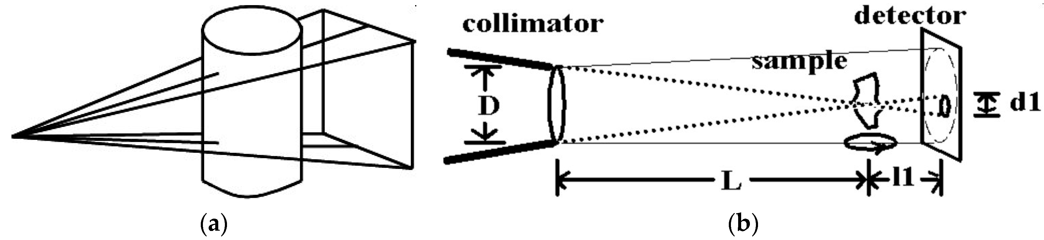
Using an X-ray tube, the focal spot size of the electron beam on the anode limits the achievable spatial resolution. The emitted come beam projects a magnified image of the sample onto the detector, so even large detector pixels can depict fine details of the magnified sample (
Figure 1a).
In a perfectly parallel beam like at a synchrotron, the sample is projected onto the detector with its original size, so the detector resolution limits the achievable spatial resolution. For neutrons, the beam geometry is an approximation to a parallel beam (
Figure 1b), so there is no inherent magnification.
The smallest diameter D of the collimator acts like a pinhole camera that projects the source area (usually the nozzle end of the beam tube into the reactor) onto the detector. But the collimator also acts as an effective source area (compared to the focal spot in an X-ray tube) that determines the achievable spatial resolution by the angular range of neutrons that hit the sample. Collimation is defined as the ratio of the sample to source distance L and the smallest collimator Diameter D (
Figure 1b). Since L is usually rather large (several meters) in the neutron case, L is often also defined as the distance to the detector, provided the sample is placed close to the detector. Any point on the sample will see incoming neutrons from D up to the angle towards the edges of the opening D. The point will thus be projected onto the detector in distance l1 as a disk with diameter d1 as geometrical unsharpness. To achieve small geometrical unsharpness d1, l1, and D should be small, and L should be large—i.e., the sample should be placed close to the detector, but far away from a small diameter collimator. The same formalism is true for X-rays, but L and D (the focal spot) are very small for an X-ray setup.
For neutrons, the employed scintillation screen finally limits the achievable resolution by the range of the reaction products of the nuclear detection reaction 6Li(n,α)3H + 4.7MeV for a ZnS + LiF screen, or 157Gd(n,e-)158Gd + 157keV for a Gadox (Gd2O2S) screen, which is usually in the range of 50–80 μm. Resolution can be improved to some extent by using thin screens, reaching a few μm with Gadox.
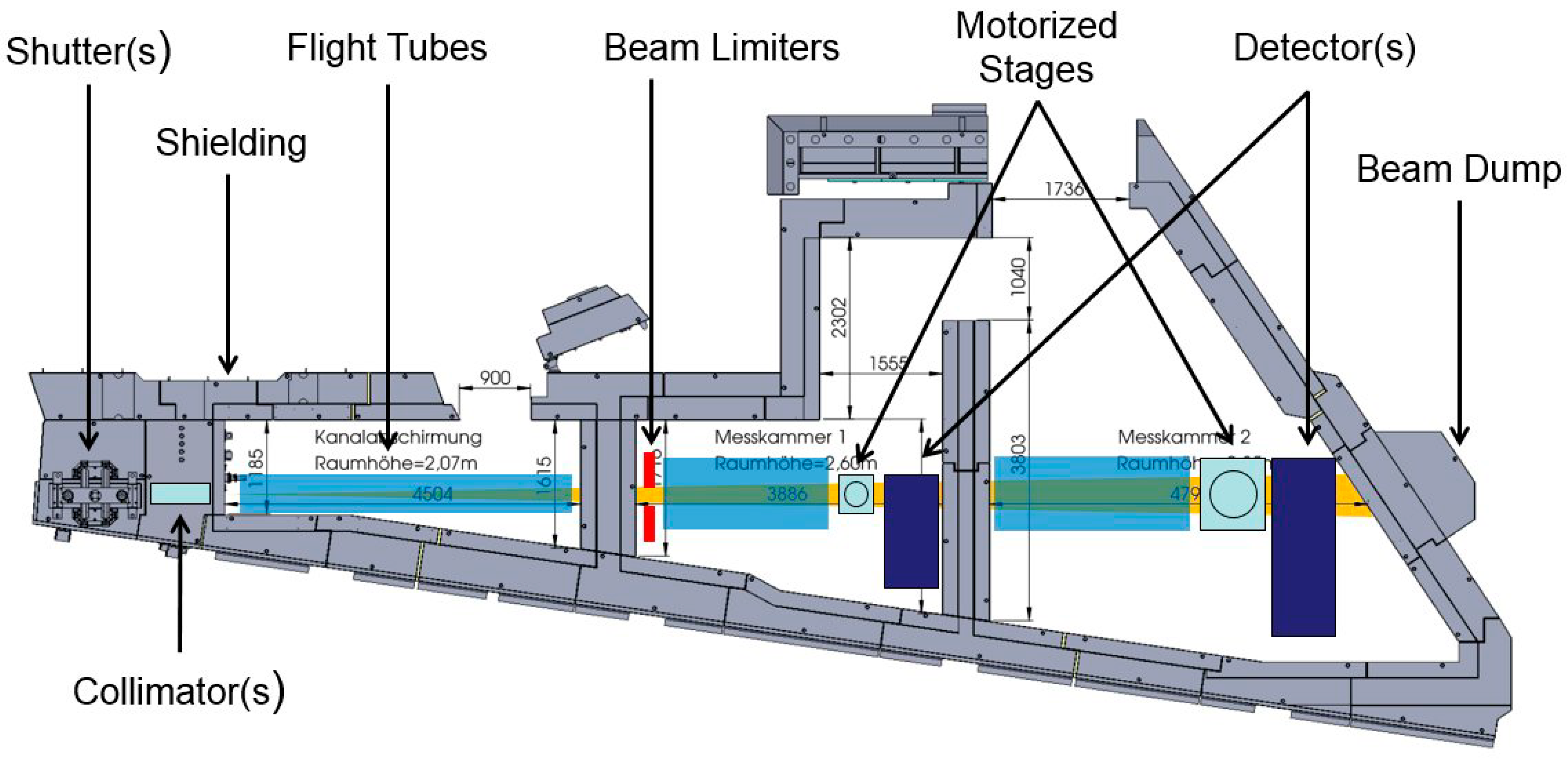
Figure 2 shows the ANTARES neutron imaging facility at the FRM II reactor.
3. The Detection System
Using a neutron or X-ray scintillation screen, a camera must be placed out of the direct beam, viewing the screen via a mirror, since the silicon chip of the camera itself is sensitive to neutron, gamma and X-ray radiation, which may either damage the chip or generate local charge clouds that appear as white spots in the image. The camera must therefore be shielded against scattered radiation using lead and borated polyethylene or similar. Most detectors with high-end cameras use massive shielding directly around the camera that reduces flexibility. The standard high-end detectors at ANTARES use an Andor scientific cooled CCD camera and a cooled scientific CMOS camera with about 200 kg of lead and borated polyethylene shielding directly around the camera.
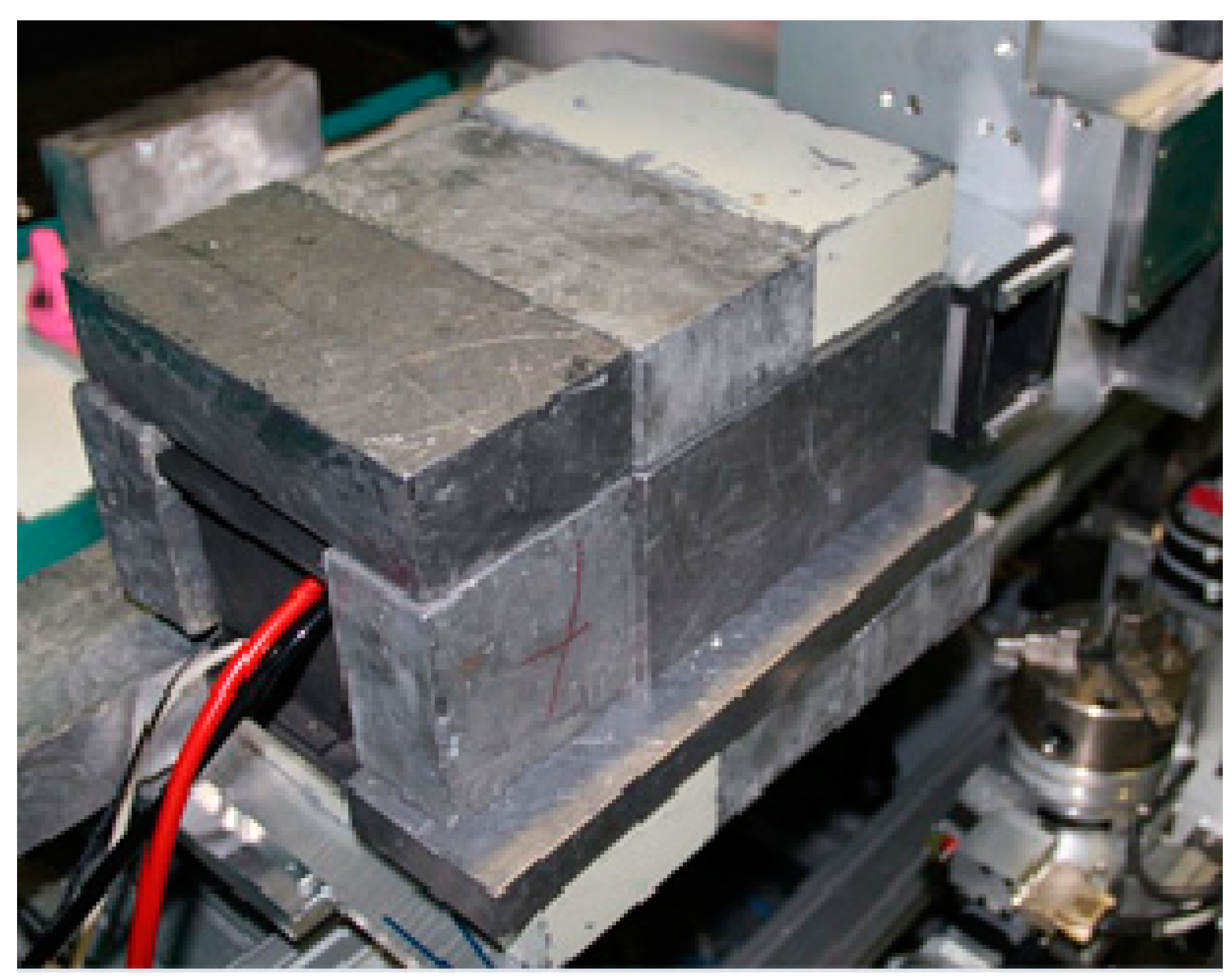
For our small detection system, we designed a detector housing as small as possible around the camera that incorporates shielding only at the front of the camera around the lens to cut direct sight to the scintillation screen (
Figure 3). External shielding must be stacked around the detector housing using lead bricks and borated PE. In addition, the mirror and scintillation screen are mounted in a separate housing that is connected to the camera housing by a flange, which allows for rotating by 180 degrees, i.e., facing the other way, and also for exchanging mirror boxes with different sizes and fields of view. The external shielding design also allows for stacking and combining several camera boxes with a single joint shielding, as described in [
1]. The original design was intended to make better use of a large field neutron beam when only small samples are to be examined with high resolution by stacking four detectors using two separate rotation axes for four simultaneous tomography measurements.
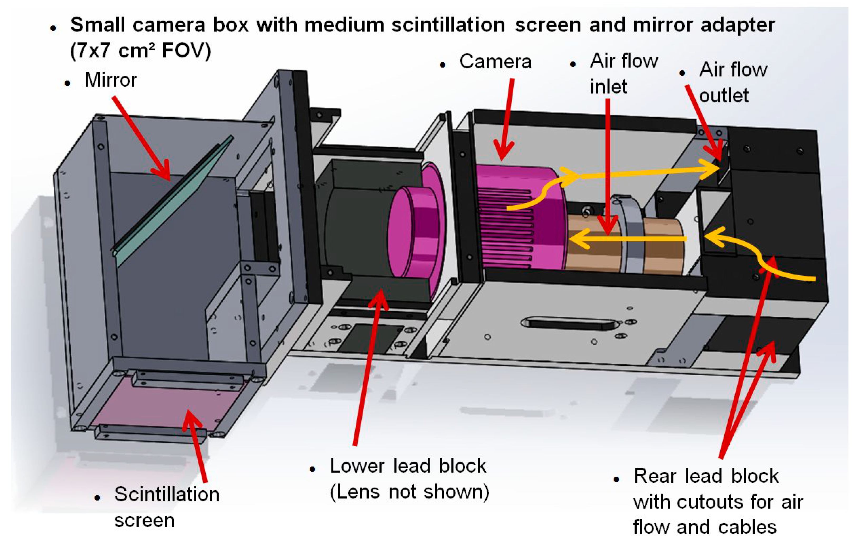
The detector housing and the external shielding impede the air flow for the air-cooled Peltier cooler of the camera, so we designed an external water-cooling ring (
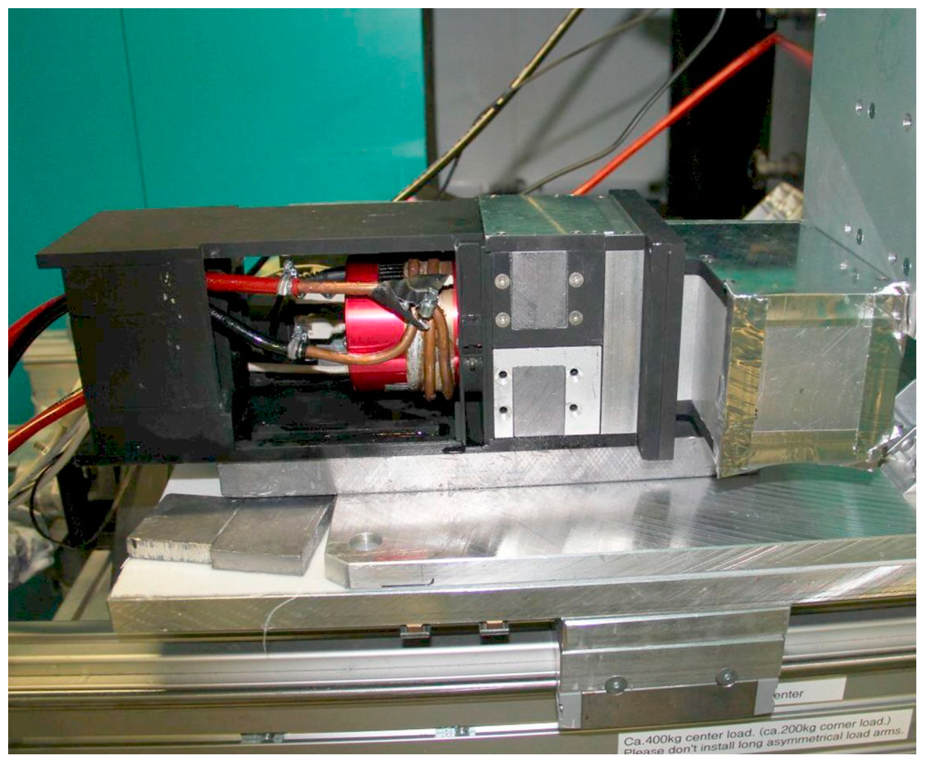
Figure 4) to ensure cooling within the stacked shielding (
Figure 5). The design uses a 14-bit ASI178MM-cool camera by ZWO [
2] which just went out of production at the time of writing. The camera QHY 178Mcool by QHY [
3] uses the same chip and has nearly identical properties. Additional distance rings between lens and camera housing are required to focus on such short distance to the screen since normal lenses can only focus distances beyond one meter. Five millimeter spacers can be bought for C-mount lenses, but depending on the lens, additional or alternative thinner washers may be needed between camera body and lens. Since the camera uses an adapter from T-40 telescope mount to C-mount, washers may also be inserted between camera body and this adapter. The correct distance must be tried out.
A Gadox screen can be used either for neutrons or X-rays. A cheap source for Gadox screens are old medical X-ray film cassettes containing screens as ‘amplifier foils’ that are often found on ebay, which can deliver first images, but are not optimized for neutron imaging or high resolution X-ray.
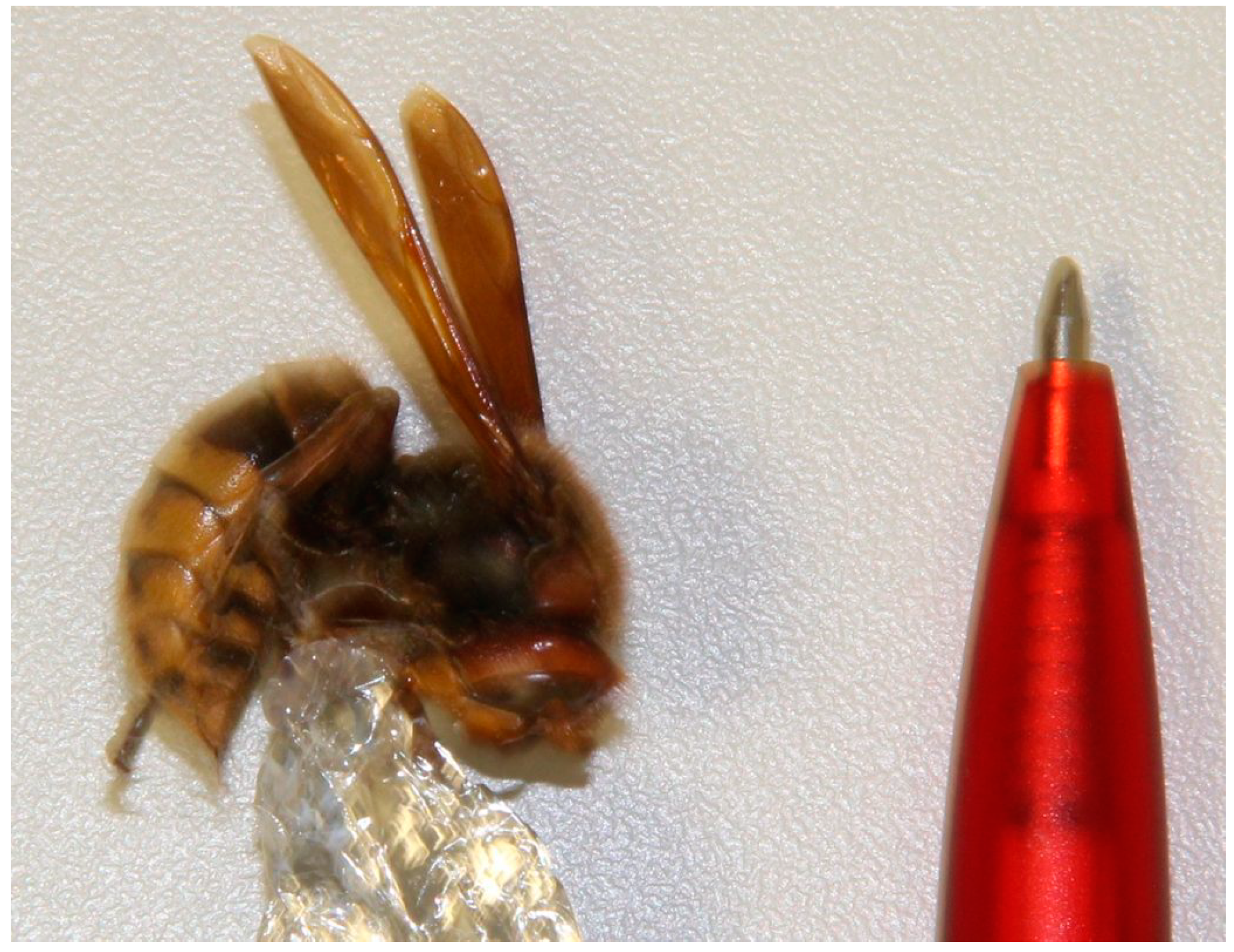
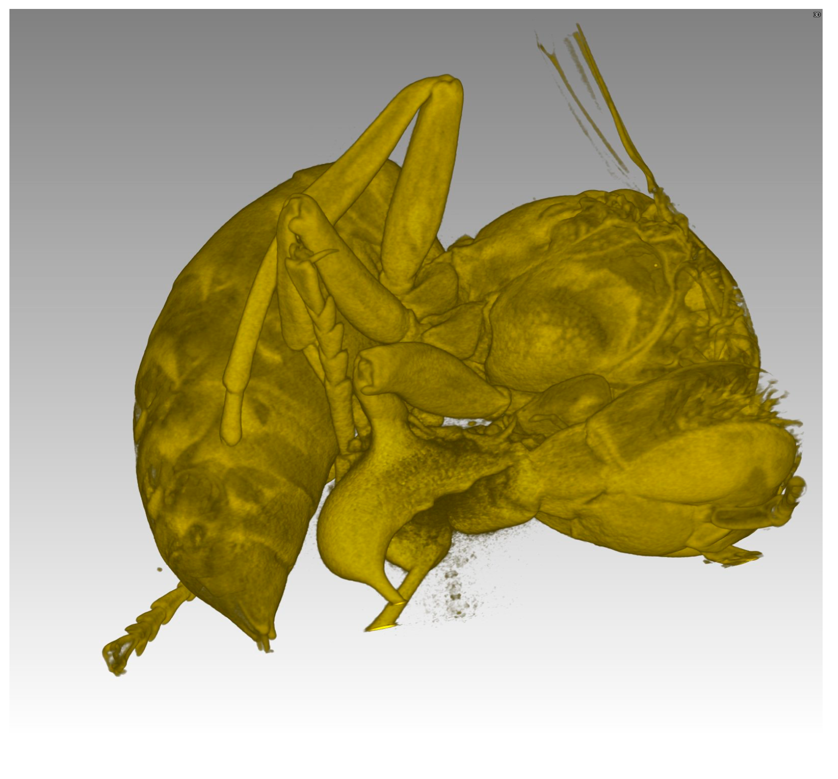
Figure 6 shows a photo and
Figure 7 a high-resolution neutron CT of a dried hornet calculated from projections with 9 µm effective pixel size (screen area projected onto one pixel) using a professional neutron screen. The calculated voxel size is a 9 µm cube.
In its second generation, the camera box design was simplified so it can be produced in any standard workshop with a drill and simple milling machine. Provided the parts are produced internally, the main costs are just the camera. Drawings for the camera box are available from the author on request.
4. Integration into a Professional Control System
The Heinz Maier–Leibnitz Zentrum at the FRM II reactor uses a network-distributed control system employing software servers written In TANGO [
4] that interface local hardware command requirements as steps and pulses into every-day units like millimeters and seconds. These servers are controlled by a graphical user interface and control system named NICOS [
5] that can use direct commands, widgets, or python script files. The camera is controlled by a LiMA server [
6].
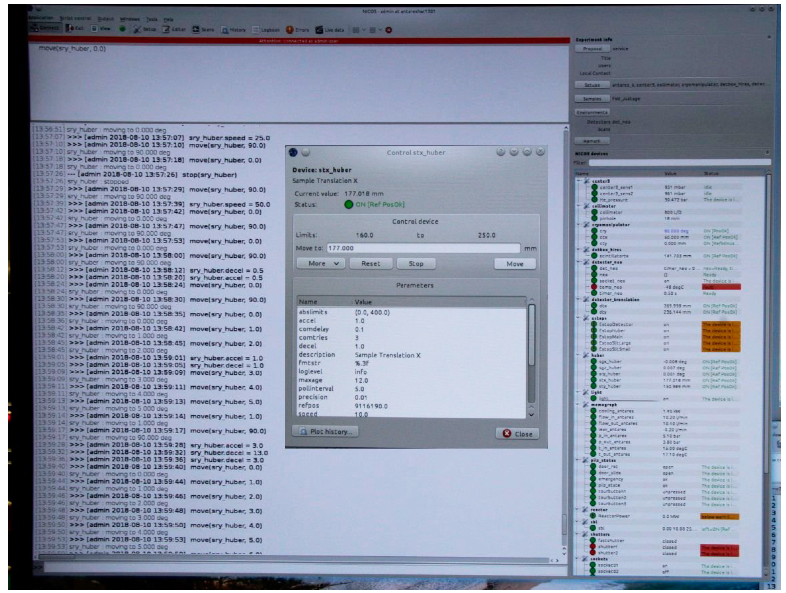
Figure 8 shows a screenshot of the NICOS control software with the history and command line window, the device list and a control widget for a single device.
In a collaboration with Idaho National Lab, where neutron imaging of highly radioactive samples is currently moving from film to digital systems, the Tango/NICOS control system of the FRM II imaging system ANTARES was downscaled to be installed first on three Raspberri Pi computers, later on a single Linux PC that controls the camera, rotation stage and two translation stages [
7]. The new system recently recorded the first neutron CT of irradiated fuel worldwide.
TANGO, NICOS, and LiMA are open source, the downscaled system can be copied, but integration of specific cameras or stages requires considerable expertise and work.
5. A Simple Test System for CT and a Hack to Use Vendor-Specific Software
For new neutron or X-ray CT systems, it is desirable to be able to conduct quick tests of feasibility, and tests of the new hardware. This is especially true when feasibility of CT on an older reactor must be proven first before funding for a professional system can be obtained. It must be noted that many older reactors and their beam ports deliver beams of rather low collimation, which will deliver unsharp images. After proving feasibility, a major effort must go into building an appropriate high-collimation beam system that is capable of delivering high definition images. As a rule of thumb, a collimation of L/D = 100 should be regarded as absolute minimum for reasonable imaging.
Most scientific cameras come with their own software, or third-party software like astronomy imaging software such as SharpCap [
8] or oaCapture [
9]. These softwares allow users to control about every single possible parameter of a camera, and also to define image sequences that require individual trigger by mouse click. But there is usually no way to interface such software to any motion control software and synchronize with it.
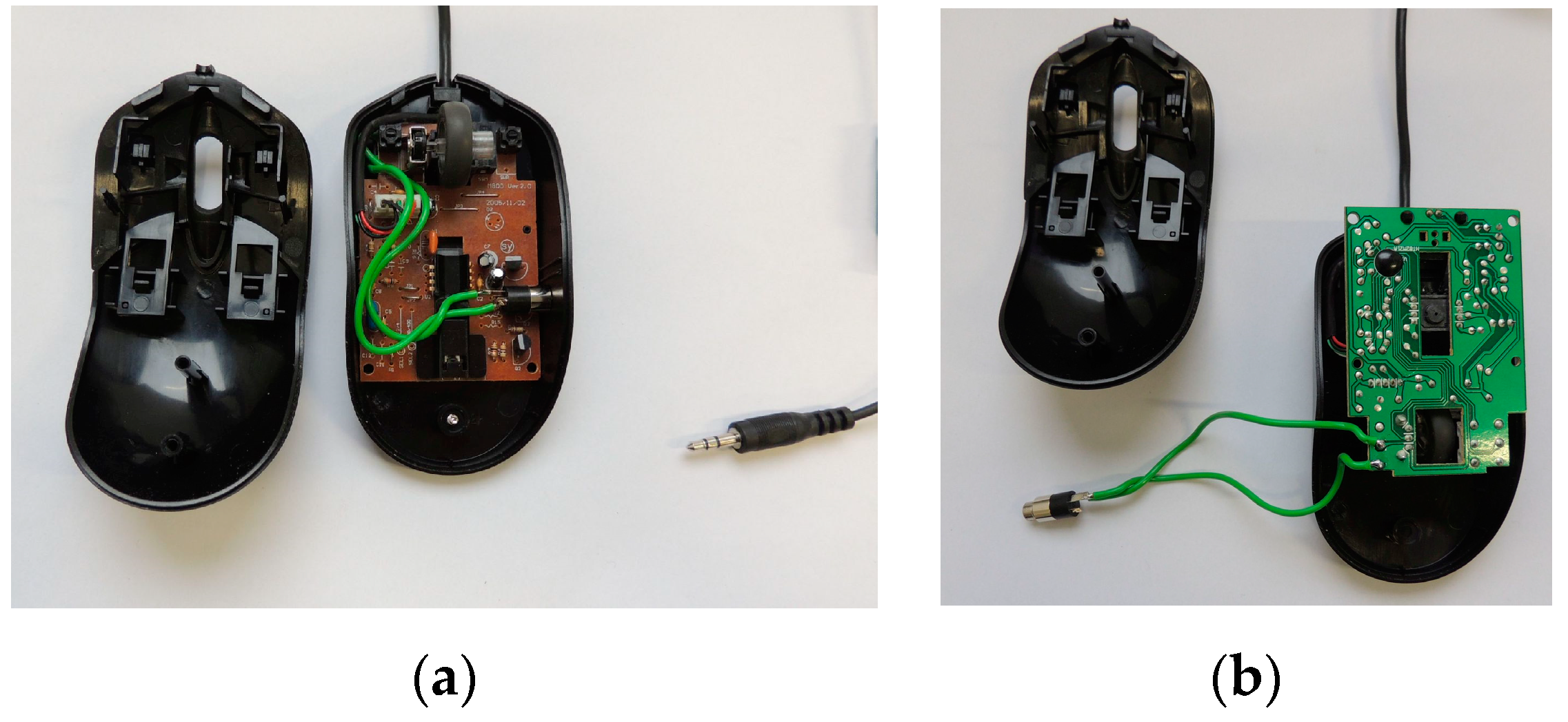
Our hack consists in using a modified computer mouse where the left mouse button can be connected via a second cable to a digital output on a second or even on the same computer. The second computer controls the motion sequence for the computed tomography in a script and delivers the trigger signal for camera exposure by clicking the mouse on the first computer after the user has moved the mouse pointer onto the start or trigger button on the camera software. No further interface to the camera software is required.
Figure 9a,b show the modified computer mouse with an extra jack connected to the pins of the mouse button. A standard stereo jack cable is used to connect to the extra computer.
While the aim for a professional user system is of course a fully integrated software system for a CT setup using original camera software libraries, this hack gives quick access to nearly all possible parameters of several dozens of cameras already integrated into the original or third-party camera software, which can be tested thoroughly for the future professional control system.
6. CT Motion Controller using a Raspberry Pi and a Gertbot Motor Controller
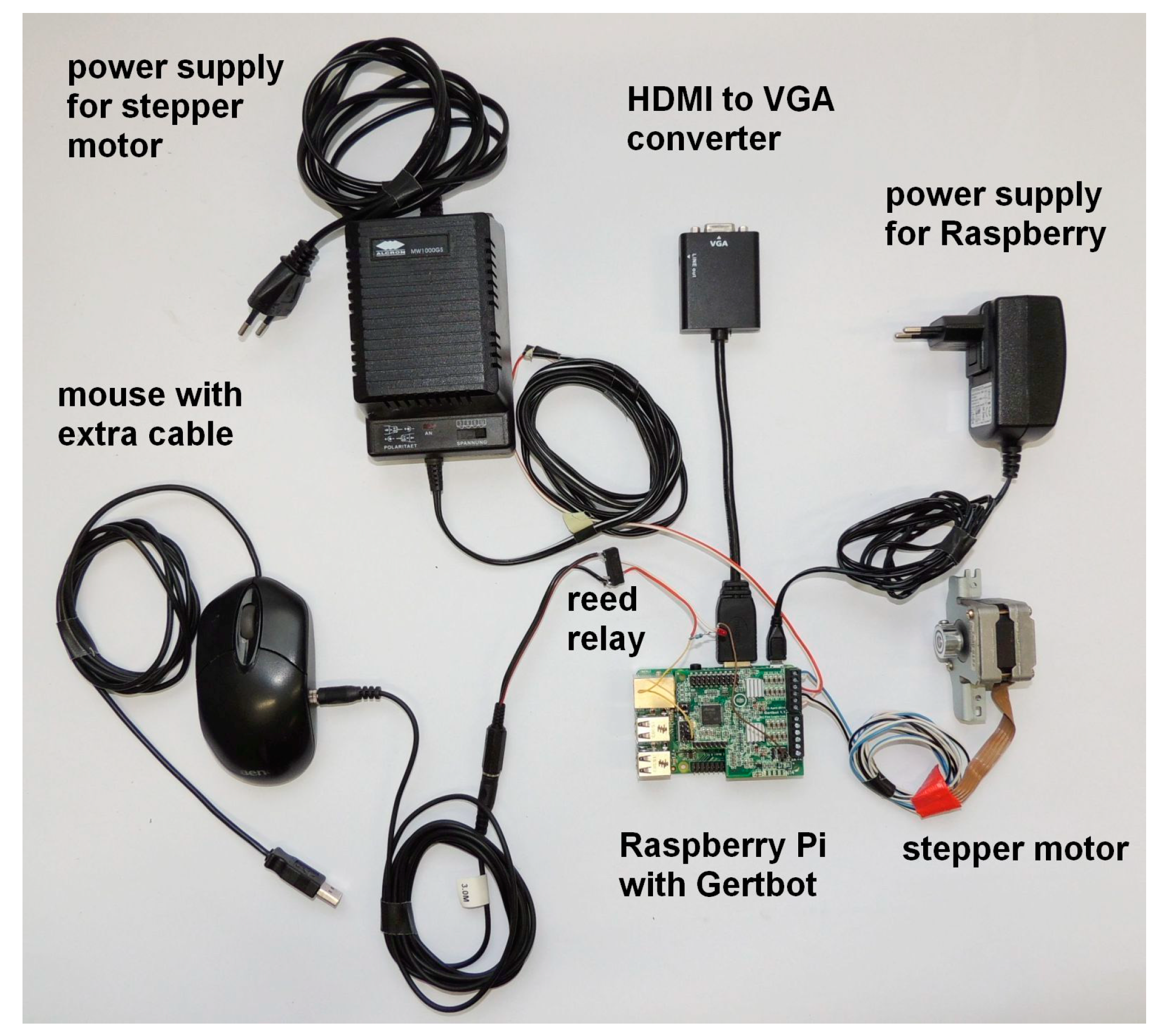
For our simple test system, we have used a Raspberri Pi computer and a Gertbot motor controller, which comes as a piggyback board for the Raspberry Pi. The Gertbot [
10] can control two stepper motors and can thus be interfaced to any motion stage, although reading an optical encoder for position feedback is not foreseen. Up to five Gertbot boards can be cascaded to control up to ten motors. As the MOSFET drivers need an external minimum voltage of 8 V (30 V max), some motors may need power resistors connected in series to match the required current. One of the two open collector outputs on the Gertbot is connected to a small 5 V reed relay, of which the switching contacts are in turn connected to the left button of the modified computer mouse.
Figure 10 shows an assembly of the required parts.
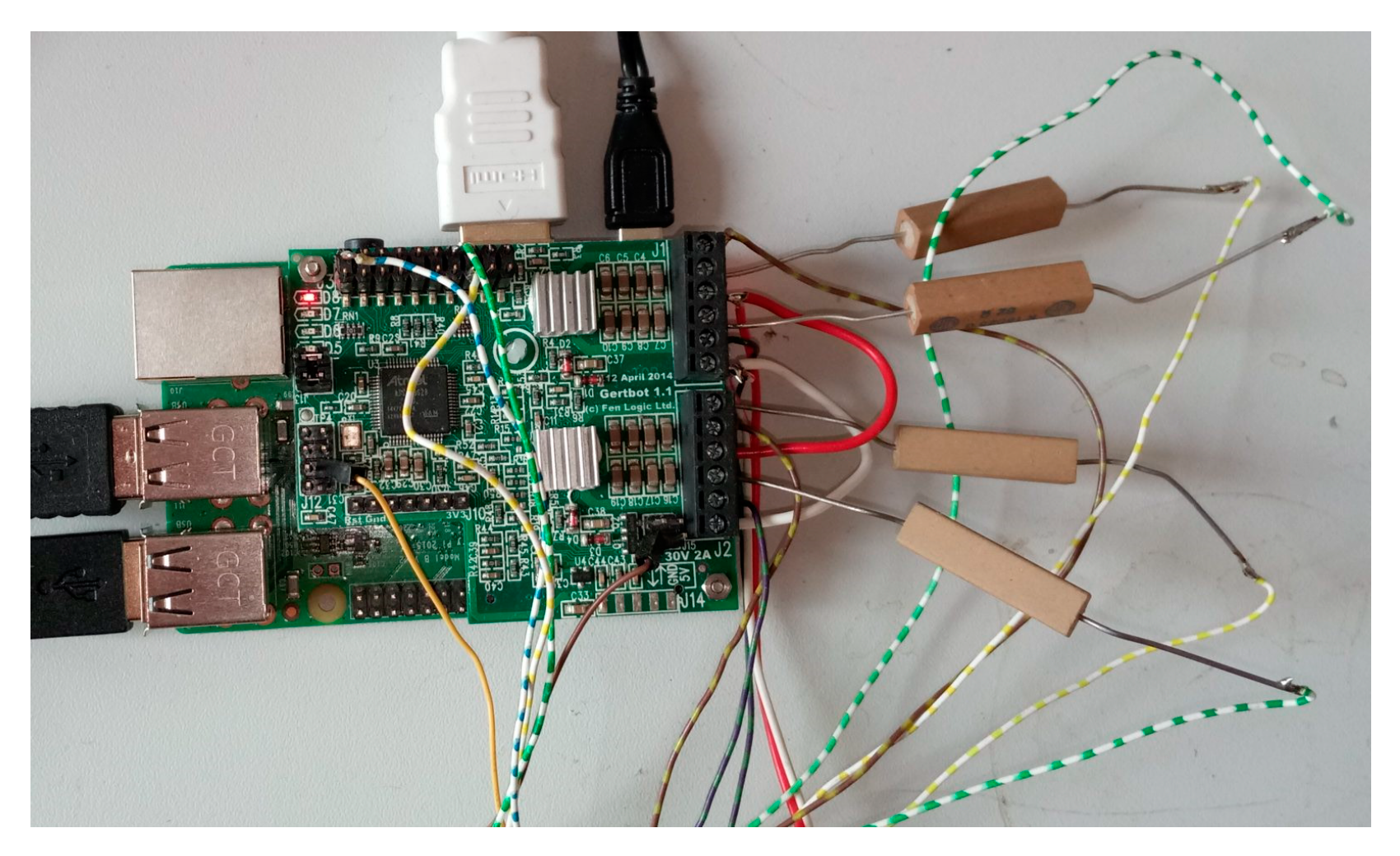
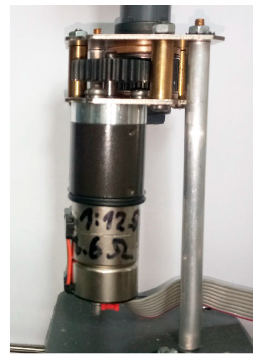
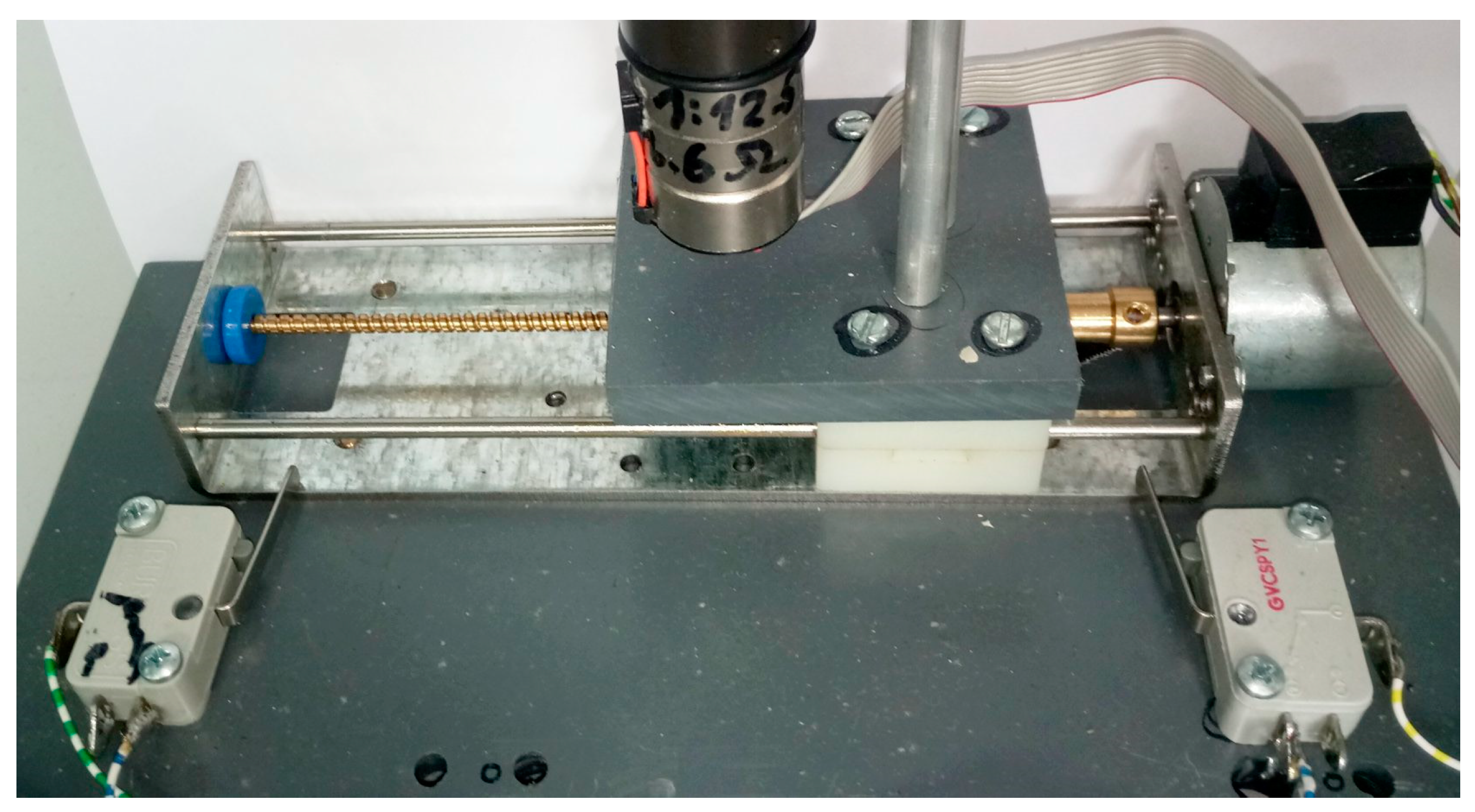
Figure 11 shows the Pi and Gertbot with additional power resistors to match the required current for the stepper motors. As a cheap rotation stage, many scientists (including the author) have used a simple single stepper motor with a small table on its axis for first trials. However, its angular resolution of only 200 steps per full rotation is insufficient for high-resolution tomography if the controller cannot do micro-steps. Since professional rotation stages usually cost several thousand euros, a simple solution is employing a stepper motor with an attached reduction gearbox (
Figure 12). For automatically recording the required open beam reference image, the rotation stage and samples must be moved out of the beam. Any stepper motor and spindle may be employed to build a translation stage, but we found a cheap linear stage on ebay that may have been employed in a printer or similar. Precision is not an issue, since no absolute positioning of the rotation stage within the field of view is required.
The center of rotation and the tilt of the rotation axis are later determined by software before reconstruction. For the rotation, any play or contouring within the gearbox is not an issue as long as all positions are approached from the same side.
Figure 13 shows the motor with gearbox mounted on the translation stage, which in turn is mounted on a small plastic board with additional limit switches. These are connected to the Gertbot and halt movement by hardware without further programming. Thus they also serve as reference switches.
7. The Control Software
The control software is available from the author on request. The software requires the turnaround time for the camera including time for exposure, data transmission and storage before it is ready again, the translation ratio of the stepper motors from steps to degrees or mm, and the number of projections over 180 or 360 degrees. The script has a delay of five seconds to give the user time to move the mouse onto the start button of the camera software. A Raspberry Pi 3B is powerful enough to run both the motion control software and the camera software on the same computer, the user only has to move the mouse pointer from the shell window to start button on the camera software.
Figure 14 shows a screenshot of the script window and the camera software with multiple camera parameters.
The second open collector output of the Gertbot may be used to control a beam shutter (or light source, see below). With the beam closed, the script first collects a number of dark frames or offset images, then moves the rotation stage out of the field of view to record open beam or reference images with the beam turned on. The rotation stage is then moved back into the field of view, and the tomography sequence is started. The software calculates the number of steps required to come as close as possible to the next angular position. Since a stepper motor with attached gearbox usually provides less reduction and thus less accuracy than a professional stage, rounding errors will occur, which are minimized by adding the number of previous steps to a counter, then calculating the number of steps to the next position starting from the zero position. Then, the difference of the two numbers is used as the next number of steps, and is then added to the counter.
The control software is a simple python script with no graphical user interface in order to keep it as simple as possible. Anyone may add a GUI, but then, this test setup is explicitly NOT recommended as a professional system.
8. CT Recording Strategy
Mathematically exact, a CT reconstruction requires Pi/2 times as many projections as the maximum width of the sample in pixels [
11]. However, this seems to be an asymptotic curve, and with other sources of unsharpness, much less projections deliver good results. In a quasi-parallel neutron beam, about 900 projections for a 2048 pixel camera deliver very good results. Using 1200 projections shows an improvement in quality that is noticeable, but usually not worth the extra measurement time. For a parallel beam (opposed to the cone beam from X-ray tubes), the second half of a full rotation is identical to the first half, save for a flip and shift of the image, and does not introduce additional angular information. Although a range of 180 degrees would be sufficient for a parallel beam CT, doing a full rotation is desirable to reduce beam hardening artefacts. To avoid doing a repetition of images in the second half of the rotation, we use an odd number of increments to reach 360 degrees, so the position 180 degrees is never reached exactly, and the projections of the second half do not coincide with the projections of the first half of the full rotation. The exact 180 degree position is still required for the determination of the rotation axis and its tilt, so we record the 180 degree image first, then rotate back to zero degrees to begin the full CT scan. To avoid contouring errors by the gearbox of the turntable, the table may turn back beyond zero degrees to a negative value, then switch direction to approach zero degrees from the same side as the 180 degree position.
9. Trying out with Optical Light
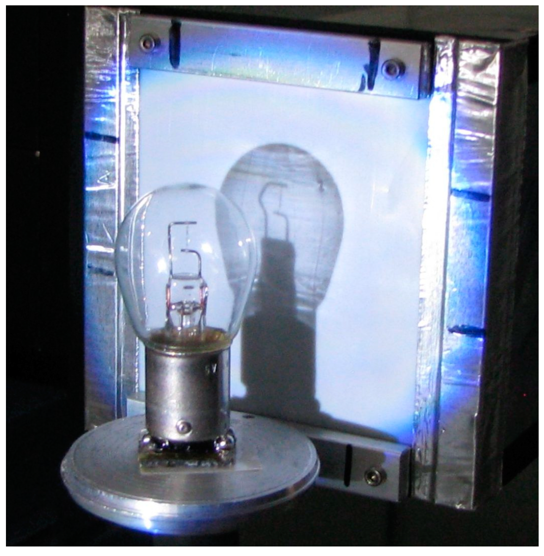
To test the system and the data processing chain in the absence of a neutron or X-ray beam, an optical light source may be used if the scintillation screen is replaced by a translucent matte screen to project the image to. To project a sharp image, a near-parallel light source is required, which may either be an old slide projector with a lens or a quasi-point source like a bright LED spotlight in sufficient distance. In many cases, the light source may still be too bright, which can be remedied by larger distance and/or an additional pinhole (some mm) in a piece of cardboard.
The sample must be transparent or translucent, or at least it must be convex in all directions (rounded, not indented, with no cavities in the surface) so all parts of the surface may be touched by tangential rays during rotation. A light bulb seems to be an ideal test sample, although irregularities in the glass bulb will produce refraction and thus artefacts. Massive objects like glass or plexiglass objects are ill-suited, since round parts will produce focusing, and flat surfaces will produce refraction and reflection, resulting in double images.
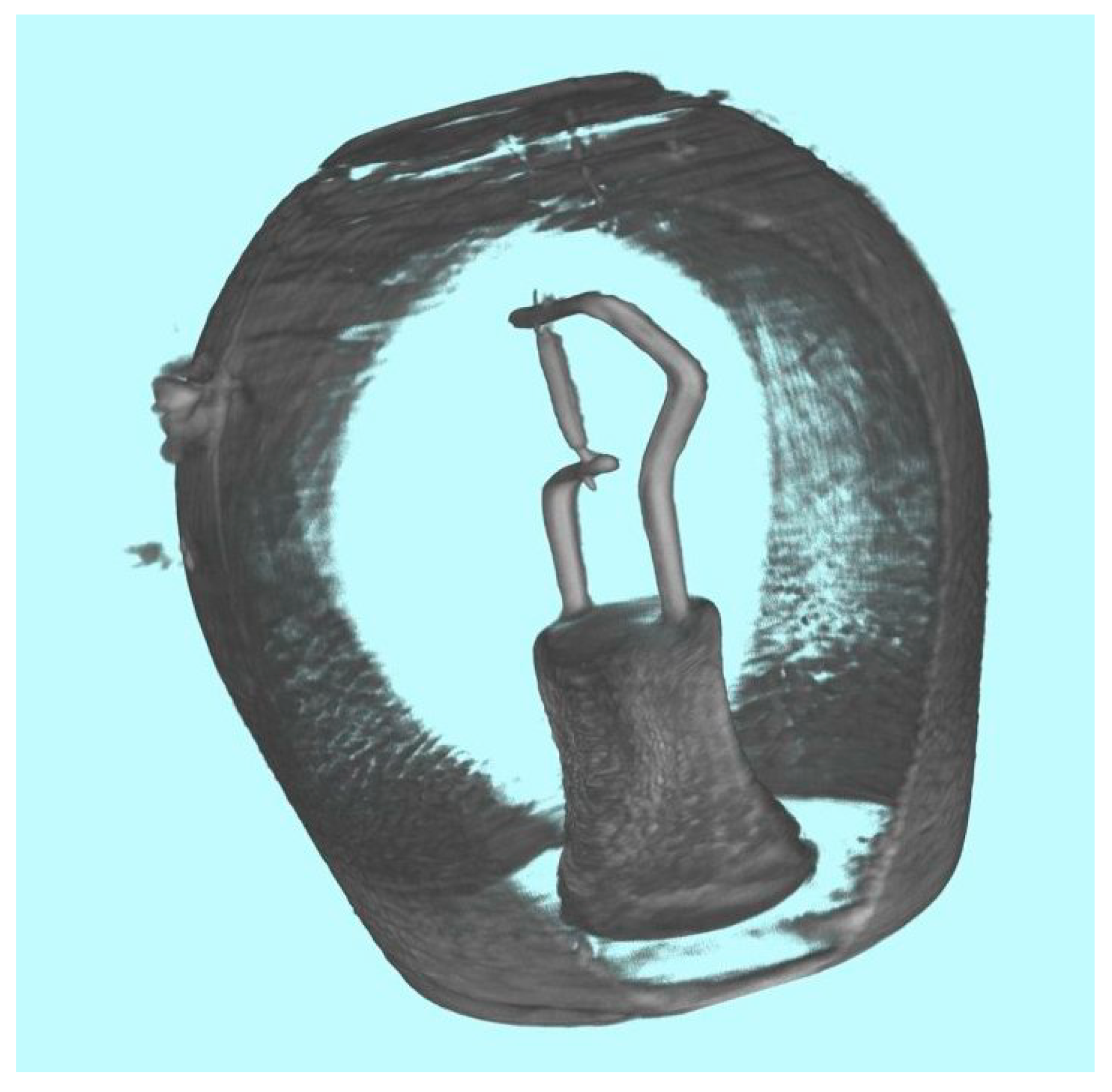
Figure 15 shows the projected image of a light bulb,
Figure 16 an optical CT of the light bulb (cut-open view) recorded with the camera box and camera described above. Of course, the optical CT does not require a camera box and mirror at all, the camera can be placed directly behind a matte screen. The recorded images may be moved to a more powerful computer with sufficient memory for reconstruction using the network, or a USB memory stick. Several free and professional softwares are mentioned in [
12], but processing is even possible within ImageJ [
13] or the extended version Fiji [
14] using the modules TomoJ [
15] and VolumeViewer. Preprocessing like dark field and open beam correction as well as determining center of rotation and correcting tilt, then performing the logarithm, have to be done by hand in ImageJ.
10. Data Processing of Raw Images with ImageJ/Fiji
All Images need to be normalized to the beam profile, i.e., divided by an open beam image that contains the intensity distribution of the beam. In addition, every camera has a little fixed offset from zero so that the analog-to-digital converter never gets fed negative values which might arise from noise symmetrical around zero. The camera chip also produces thermal charges that cause additional offset and noise. To correct for that, dark frames of identical exposure time without an image signal are subtracted from both the projections and open beam images before the normalization.
If ImageJ is used, open the data projections, the dark frames and open beam images as stacks in ImageJ. If the computer has little physical memory, select ‘Use virtual stack’. If necessary, remove white spots from the images using process/noise/remove outliers with appropriate values. Combine open beam images and dark frames into one image each using Z-Project/median filter, subtract the dark frame from the open beam and all projections. Divide the projections by the corrected open beam, selecting 32-bit output. Crop the image stack to sample size.
Then, the center of rotation and a potential tilt of the rotation axis must be determined. If the rotation axis was perfectly centered and upright, the zero- and 180-degree images would be identical, save for a horizontal flip of the 180 degree image.
Subtracting the flipped 180-degree image from the zero degree image will thus result in an image close to zero. If the rotation axis is not aligned, dark and bright edges will appear. With the width of these edges measured, half as many columns need to be cut off the original images on either the left or right side until the subtraction delivers near-zero and the edges disappear. Similarly, if the rotation axis is tilted, both original images need to be rotated until the subtraction delivers near-zero.
In ImageJ, duplicate stack (for backup), then duplicate 0° and 180° image and find shift and rotation: Flip 180° image horizontally, subtract 0°–180° image, measure shift, optimize shift, find rotation center, find tilt value by rotating the images.
Remove the 180° Image (the first one) from the original stack, perform –log on the data, since the image signal I corresponds to the open beam signal I0 as I = I0*exp(-µx), so the attenuation coefficient µ is calculated as µ = −log(I/I0). Shift and rotate by half the shift values found above, then start TomoJ.
Set tilt angles and Normalization: None. Reconstruct: Set Thickness = Width, select Weighted Backprojection, Select Weighting, deselect GPU if you experience problems during reconstruction.
Use Volume Viewer for visualization. The transparency of the reconstructed materials must be adjusted until empty space or air becomes invisible, and the sample becomes visible in 3D.
11. Conclusion and Summary
We have used a new cooled astronomy CMOS camera to build a low-cost, but high-quality detector for X-ray or neutron computed tomography that delivers professional results. The field of view may be varied by selecting lenses different focal lengths, and/or by exchanging the separate housing with mirror and scintillation screen for different sizes. The detector may be integrated into a professional control system or be used with a simple CT motion controller based on a Raspberry Pi that also controls the native camera software on a separate computer. The whole setup may be dry-tested using an optical light source, a matte screen and a transparent test sample.
All these different setups are intended to help to prove the feasibility of computed tomography at a neutron or X-ray source, to obtain funding for professional components after getting first quick results, and to test components and setups quickly before a professional control system is established. The setup with optical light is sufficient to run a full tomography measurement and test the data processing chain for training and teaching even without an expensive radiation source.
The mouse hack shown here may also be used to start any other process for neutron and X-ray measurements on a separate computer, like a motor, temperature controller, or other process in a sample environment.
A detailed instruction manual will be available from the author in the future.


