Article

Influence of Gate Depletion Layer Width on Radiation Resistance of Silicon Carbide Junction Field-Effect Transistors

1
National Institutes for Quantum Science and Technology, 1233 Watanuki-Machi, Takasaki 370-1292, Japan
2
National Institute of Advanced Industrial Science and Technology, 1-1-1 Umezono, Tsukuba 305-8560, Japan
3
Research Institute for Nanodevices, Hiroshima University, 1-4-2 Kagamiyama, Higashi-Hiroshima 739-8527, Japan
*
Author to whom correspondence should be addressed.
Quantum Beam Sci. 2023, 7(4), 31; https://doi.org/10.3390/qubs7040031
Submission received: 16 May 2023 / Revised: 9 September 2023 / Accepted: 8 October 2023 / Published: 11 October 2023
(This article belongs to the Section Instrumentation and Facilities)

Abstract

:
Silicon carbide junction field-effect transistors (SiC JFETs) are promising candidates as devices applicable to radiation conditions, such as the decommissioning of nuclear facilities or the space environment. We investigate the origin of the threshold volage (Vth) shift and hysteresis of differently structured SiC JFETs. A large positive Vth shift and hysteresis are observed for a depletion-type JFET with a larger depletion layer width. With changing the sweep range of the gate voltage and depletion width, the Vth shift was positively proportional to the difference between the channel depth and depletion width (channel depth–gate depletion width). By illuminating the sub-band gap light, the Vth of the irradiated depletion JFETs recovers close to nonirradiated ones, while a smaller shift and hysteresis are observed for the enhancement type with a narrower width. It can be interpreted that positive charges generated in a gate depletion layer cause a positive Vth shift. When they are swept out from the depletion layer and trapped in the channel, this gives rise to a further Vth shift and hysteresis in gamma-irradiated SiC JFETs.

1. Introduction

A three-times-wider band gap of silicon carbide (SiC) than silicon (Si) can effectively suppress the number of electron–hole pairs generated in devices using gamma rays [1]. Due to a lower amount of displacement damage caused by Compton electrons generated through irradiation, SiC devices are attractive for long-term use for the decommissioning of nuclear facilities or in the space environment [2,3,4,5]. In particular, the device structure of SiC junction field-effect transistors (JFETs) is of interest for electronics working in high-temperature and/or high-radiation conditions [6,7]. The gate of SiC JFETs consists of a p-type-doped region instead of the gate oxide; thus, the threshold voltage (Vth) shift caused by a positive charge (holes) accumulated in the oxide is suppressed. Less than 1 V of the Vth shift after MGy irradiation is much smaller than that of SiC metal-oxide semiconductor (MOS) FETs [8,9,10,11,12,13]. Thus far, there have been a few reports regarding the radiation effect of SiC JFETs. Most of them showed no significant degradation in device characteristics after several MGy irradiations [8,9,10]. In contrast, a Vth shift due to a positively charged passivation oxide was reported [11]. We previously reported a positive shift in Vth with increasing doses [13]. Furthermore, Vth hysteresis appeared due to sweep direction and a range of gate voltages (VGs).
The Vth shift and its instability are some of the major reliability issues studied for SiC MOSFETs. A positive Vth shift gives rise to increases in conduction losses, whereas a negative shift causes an increased drain leakage current and power consumption [14,15]. When either shift occurs in a different inverter, it broadens the distribution of the inverter’s characteristics and contributes to the reduction in the static noise margin of the static random access memory (SRAM). Vth instability would also be a reliability concern for the development of circuits using SiC JFETs. Recently, SiC complementary JFETs (CJFETs) were developed through the ion implantation of impurities in a semi-insulating substrate as components of high-temperature circuits [16,17]. Another group showed a SiC amplifier based on a 4H-SiC MOSFET that could work well up to 500 degrees whilst improving the reliability of the metal/SiC contact [18]. In addition, aiming at installing it in robots working in nuclear facilities, a Si/4H-SiC hybrid pixel device was demonstrated [19].
However, the origin of the Vth shift and the instability of gamma-irradiated SiC JFETs are not understood. In this report, SiC JFETs were irradiated with gamma rays over 10 MGy (H2O). Such a high dose of irradiation allowed for the radiation effects to be more clearly observable. By comparing the degradation behaviors between the two differently structured devices, how they occurred was investigated.

2. Materials and Methods

Cross-sectional views of n-channel enhancement-type (normally off) and depletion-type (normally on) JFETs fabricated in AIST are depicted in Figure 1. the Nominal channel length (Lch) and depth (Dch) were 2.2 and 0.6 μm, respectively. The channel width (Wch) was 72 μm. The gate and base layer were formed through the implantation of aluminum ions into an n-type epitaxial layer. The implanted aluminum concentration profile was confirmed using secondary ion mass spectrometry (SIMS) and the simulated aluminum profile [13]. Every two or three steps of the aluminum implantation to attain a box-shaped profile were carried out for each depletion or enhancement type. The source and drain (n+) regions were formed through phosphorous ion implantation. Ohmic contacts were formed through the deposition of nickel/aluminum, followed by sintering. Afterwards, aluminum contact pads were deposited.
For the depletion-type JFETs, a bottom p-type layer was electrically connected with a source n+ layer at the source contact pad. The channel region was surrounded by a thermally grown SiO2 layer (tSiO2) 1 μm thick for electrical isolation. For the enhancement type, the bottom p-type base layer and gate were connected. Accordingly, the p+ basket-shaped gate layer formed around the channel region electrically isolated each device. The surface was also passivated with a 1 μm thick SiO2 layer.
The Irradiation of the gamma rays was performed at room temperature under an argon (Ar) atmosphere to prevent the oxidation of the aluminum electrodes. The purity of the Ar was more than 99.9995 vol.%. The total dose was 17 Mgy (H2O) for the depletion and 15 Mgy for the enhancement types. During irradiation, the SiC JFETs were put into an aluminum tube inside a stainless chamber in order to maintain an approximate charged particle equilibrium. No bias was applied and none of the electrodes were grounded during the irradiation. The dose rate at the position where the JFETs were irradiated was evaluated with a PMMA (poly-methylmethacrylate) dosimeter (Radia Industry Co., Ltd., Takasaki, Japan) [20,21]. The dose rate was 9–10 kGy/h (H2O). In order to evaluate the effect of the surface-generated charges, the depletion-type JFETs were aged at room temperature in air after 17 of Mgy irradiation.
The drain current (ID) gate voltage (VG) and drain voltage (VD) characteristics were measured at room temperature in the dark using Agilent 4156B or Keysight B1500A semiconductor parameter analyzers after each irradiation. During the measurement, the source and substrate were commonly grounded and a drain voltage (VD) of 6 V was applied to the drain electrode. To investigate the changes in the electrical characteristics due to the irradiation, the VG was swept with a 10 mV interval. The delay, which was defined as the time before the acquisition of ID at each VG step, was set to 0 s. The Vth was calculated through the linear extrapolation of the square root of the IDVG curves in the saturation region. We irradiated 10 depletion and 4 enhancement JFETs with channel widths of 18, 36 and 72 μm. Each average Vth shift from that of a pristine device was 0.50 or 0.069 V. Each standard deviation was 0.1 or 0.02 V. The Vth hysteresis was investigated by changing the sweeping interval of the VG from 10 to 300 mV. Moreover, at a fixed step interval of 300 mV, a measurement was carried out for different delay times and sweep ranges.
The energy levels of the traps (defects) formed in the devices were characterized by an illuminating sub-bandgap light. The electrons are excited from the valence band to the traps formed in the band gap of the SiC [22,23,24,25]. The defects formed in the SiC are usually characterized using a thermal method such as deep-level transient spectroscopy (DLTS); nevertheless, using light illumination prevents the irreversible recovery or additional degradation of irradiated devices. Light-emitting diodes (LEDs) with a center wavelength from 745 (1.67 eV) to 1545 nm (0.80 eV) were employed as the light sources. Visible and infrared spectra features of the LEDs were investigated using compact fiber spectrometers. The averaged intensity of the focused LED light onto the JFETs was 15 μW/mm2. As the light energies were located below approximately a half of the 4H-SiC, 3.26 eV [26], the defects formed in the upper/bottom half of the bandgap were mainly excited during the illumination. By illuminating the JFETs with the LEDs, the IDVG curves were measured. Through estimating the Vth from the IDVG characteristics during the illumination, the approximate energy levels of the defects were explored.

3. Results

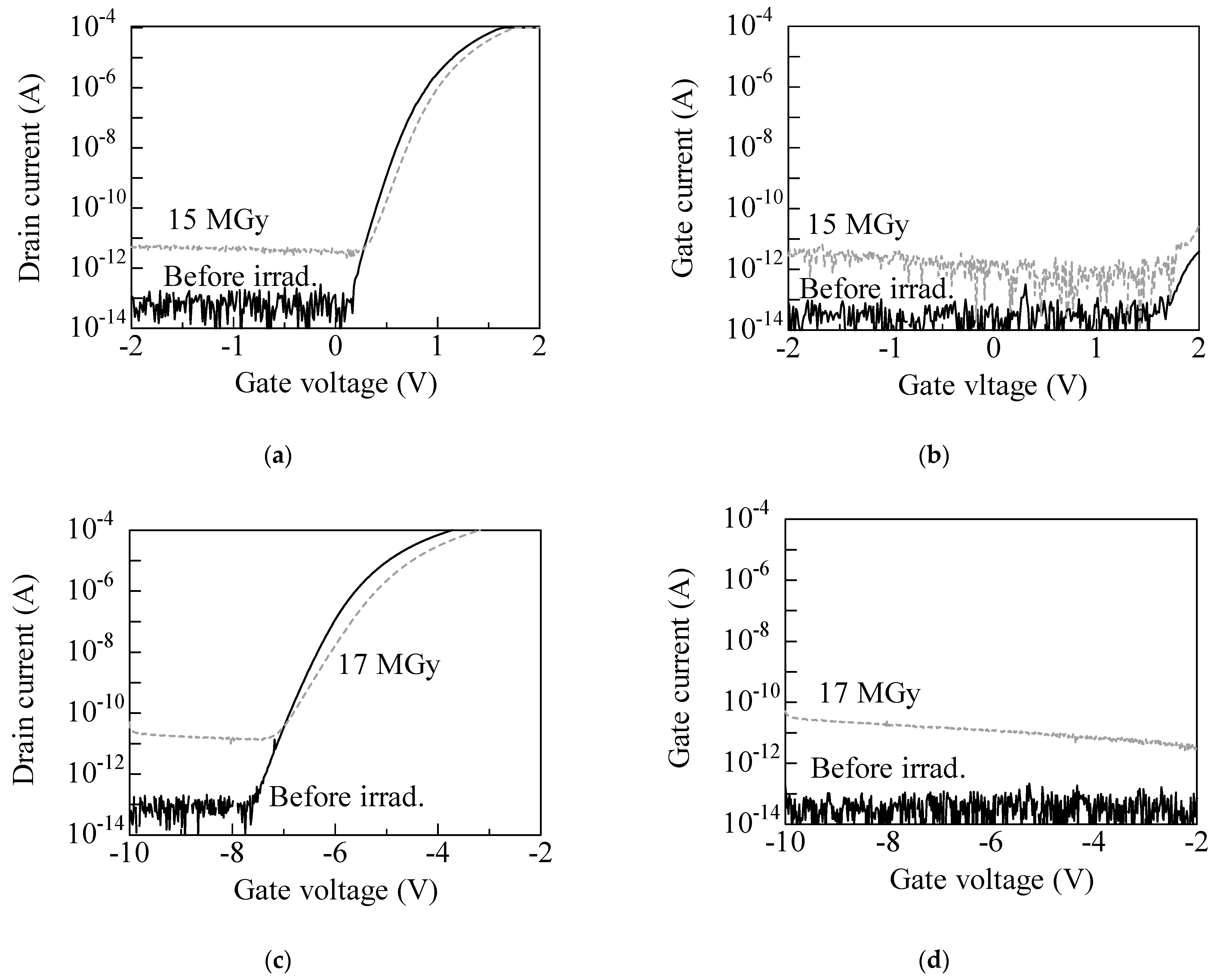
The IDVG and IGVG characteristics for the non- and irradiated SiC JFETs are shown in Figure 2a–d. Regardless of the device structure, increases in the subthreshold slope and positive shift were observed in the IDVG curves after the irradiation (dashed lines). Values of the drain leakage currents in the IDVG curves were nearly consistent with the IG leakage currents, indicating leakage paths between the gate and drain electrodes having formed after the irradiation.
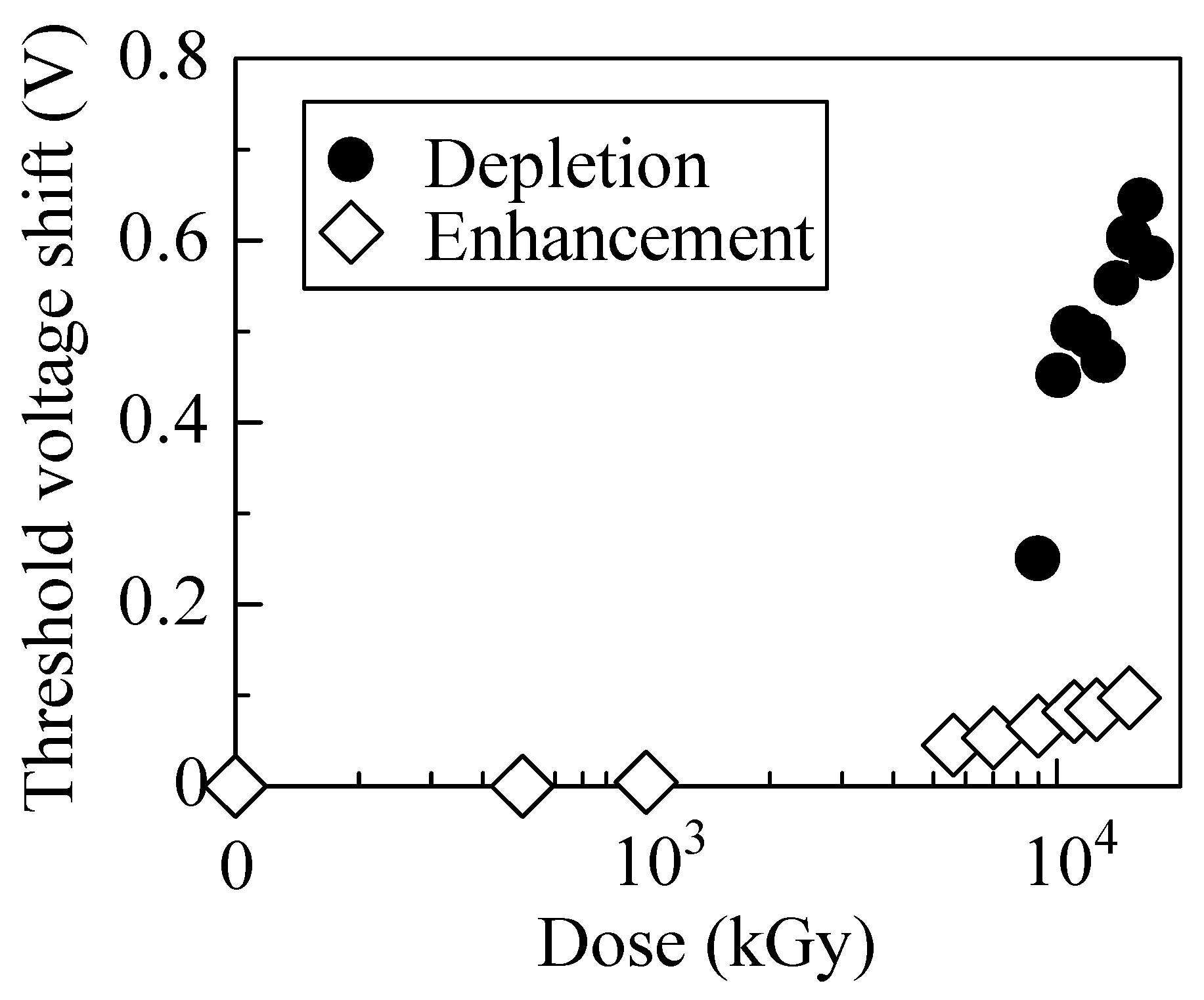
The threshold voltage shift (ΔVth) from the nonirradiated devices was plotted in Figure 3. The initial Vth of the enhancement or depletion type was 0.96 or −5.27 V, respectively. The ΔVth of the enhancement type increased positively and reached approximately 0.1 V after 15 MGy, whereas for the depletion type, a much larger positive shift was observed. Although the depletion type was a single-gated structure (Figure 1b) and the Vth was expected to be two times larger than the double-gated ones [27], the approximately six times larger ΔVth at the same dose was of interest.
So as to evaluate the effect of the charges generated on the device surface, irradiated depletion-type JFETs were aged at room temperature. As shown in Figure 4a, the leakage current became as low as that for the nonirradiated device at 1 year after irradiation. The Vth slightly shifted toward the negative direction and was saturated after 1 year (Figure 4b. Given that the leakage paths were formed between the gate and drain electrodes, it was inferred that the leakage currents were caused due to electrons attracted by positively charged passivation oxide. As holes rapped in the oxide were annealed, the apparent positive bias applied to the gate was removed. This resulted in a slightly negative Vth shift. The aging experiment also suggested that a positive Vth shift was derived from the defects formed in the bulk region of the device.
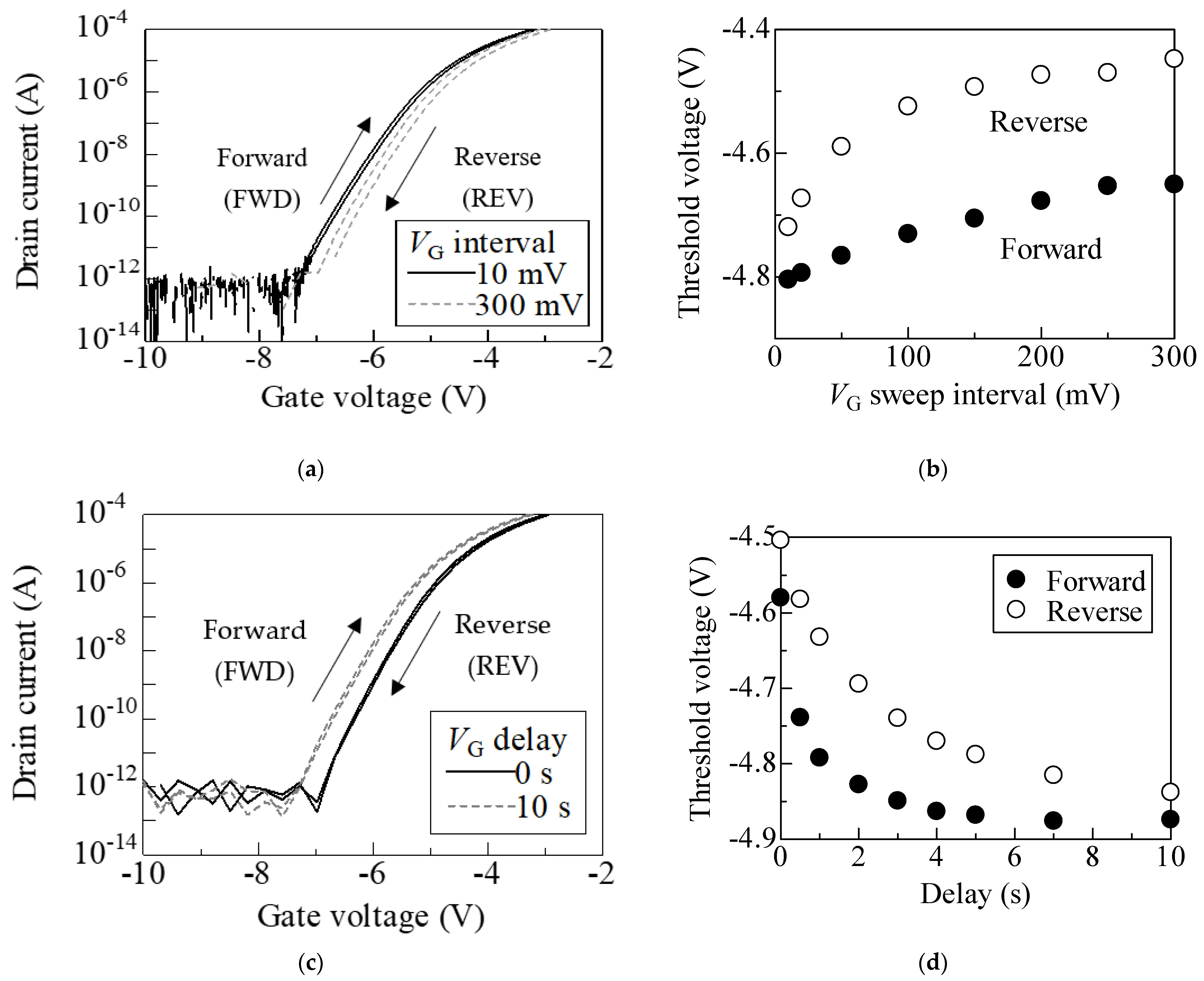
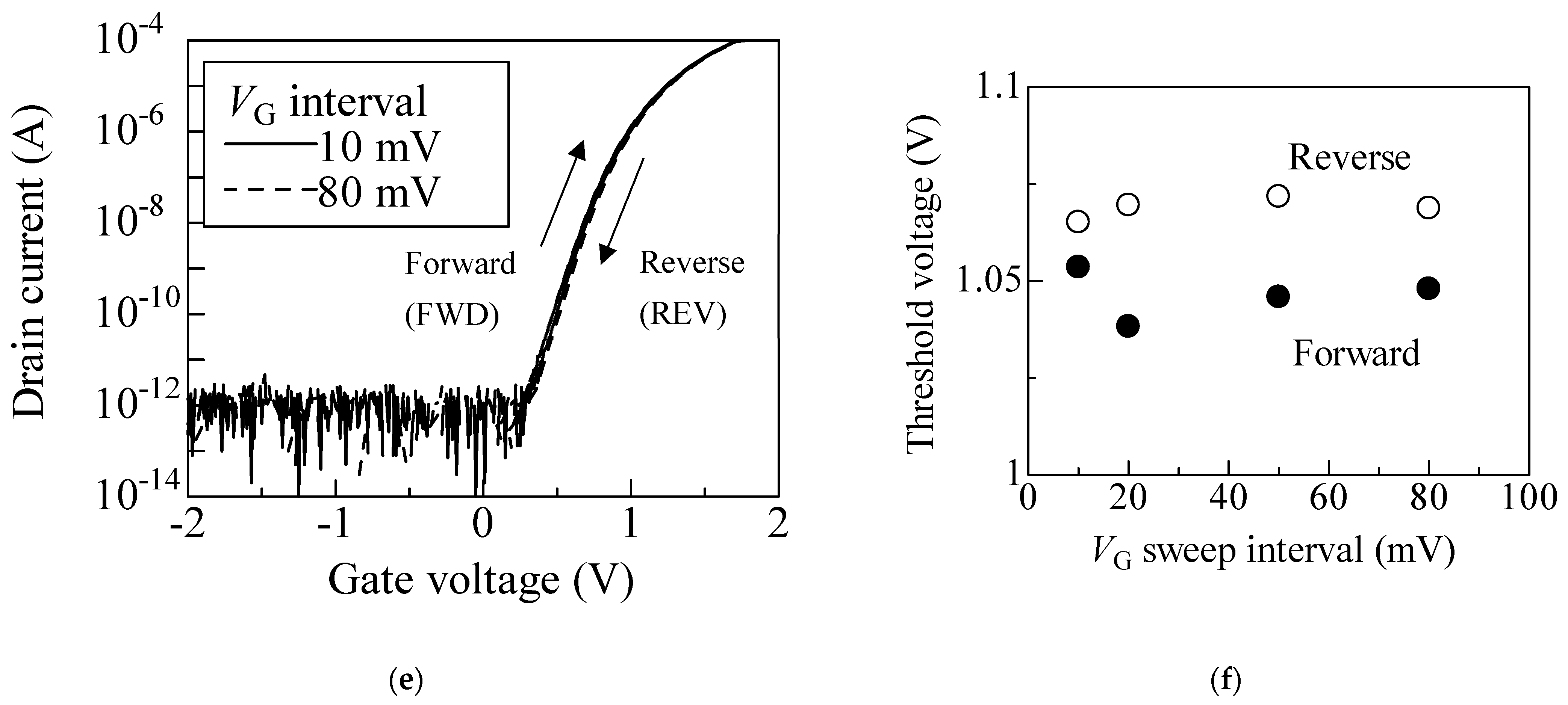
The IDVG hysteresis of the irradiated depletion-type JFETs are shown in Figure 5a. The IDVG curve positively shifted and the hysteresis became larger for 300 mV. The Vth of each sweep direction (forward (FWD) or reverse (REV)) were plotted in Figure 5b. Both Vths gradually increased and were almost saturated at 300 mV. With the VG sweep interval at 300 mV, the IDVG curves shifted negatively for a longer delay, as shown in Figure 5c. The FWD Vth plotted in Figure 5d decreased and was saturated after 4 s, while the REV Vth (brank circles) more slowly decreased to 10 s. A decay as slow as several seconds implied that carriers were captured and released via the deep hole traps [28,29,30,31]. Meanwhile, no significant hysteresis appeared for the enhancement type (Figure 5e). Due to the relatively abrupt increase in the drain current that resulted from the double-gated structure (Figure 1a), the sweep interval was limited below 80 mV to obtain sufficient data plots for the Vth estimation. The difference between the FWD and REV Vths remained within approximately 0.05 V, as shown in Figure 5f, which was much smaller than that shown in Figure 5b.
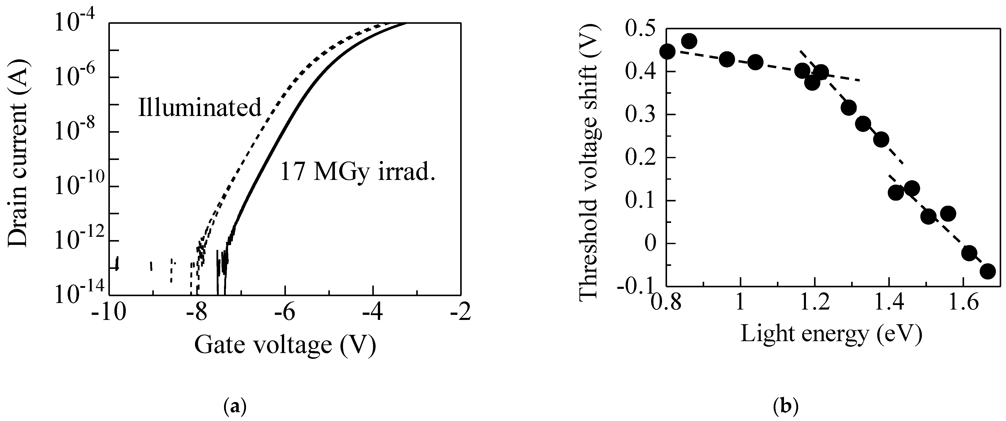
We assumed the positive charges trapped at the depletion layer served as an apparent positive bias and pushed down the electric potential of the channel [32,33]. In order to verify this hypothesis, we illuminated the irradiated depletion JFETs to excite the electrons from the valence band to neutralize the traps. The IDVG curves characterized during/without the LED illumination are shown in Figure 6a. The VG sweep interval was 10 mV and the wavelength (energy) of the LED was 750 nm (1.67 eV). The light illumination shifted the curve toward the negative voltage side, while it did not affect the leakage current. The Vth shift from the nonirradiated device (ΔVth) is shown in Figure 6b. A slight recovery as low as 0.1 V was already observed below 0.8 eV. With increasing light energy, a little steep slope at 1.2 eV and a small gap were observed at 1.4 eV. As the Vth shifted when the LED spectra passed the defect energy level, such a sudden increase or gap indicated that some defects were formed. Given full width at half maximum (FWHM) of the LED spectra of less than 0.1 eV, those defects could be assigned to deep hole traps HK3 (Ev + 1.24 eV) and HK4 (Ev + 1.44 eV) [26].

4. Discussion

The positive charges of the hole traps in the depletion layer were attributed to a positive Vth shift. We evaluated the depletion layer width of the JFETs assuming an abrupt doping profile [27]:
Ψ b i = 1 q E g k T ln N c N D
V t h V D = Ψ b i Ψ P = 1 q E g k T ln N c N D q N D a 2 2 ε s i c ε 0
W D = 2   ε s i c ε 0 ( Ψ b i + V D V G ) q   N D
where Ψbi is the built-in potential of the gate p–n junction, ΨP is the pinch-off potential, WD is the depletion layer width at the drain side, Eg is the band gap energy, q, k and T are the elementary charge, Boltzmann constant and temperature, respectively, Nc is the effective density of the states in the conduction band, ND is the donor concentration, a is the channel depth of 0.6 μm and εSiC and ε0 are the relative permittivity of SiC, at 9.8 [26], and permittivity in vacuum, respectively. Taking the drain voltage VD of 6 V, the effective donor density ND of the nonirradiated JFET was 4.3 × 1016 cm−3. For simplicity, the apparent positive VG by the trapped holes was neglected.
The calculated depletion width WD was plotted in Figure 7a. The WD decreased as the VG increased and was smaller for the enhancement type, while the channel depth–depletion width) (dashed lines) increased with an increasing VG. It was noted that that of the enhancement JFET was less than a half of the depletion type. This resulted from the short depletion width and double-gated structure, as the channel depth was 0.3 μm. Figure 7b shows the REV Vth as a function of the sweep-end voltage. The sweep interval was 300 mV. The REV Vth for the depletion type increased when increasing the sweeping range up to VG = 3 V. In contrast, the increment for the enhancement type was smaller.
During the FWD sweeping, the holes trapped at the depletion layer were swept out [13] and were then trapped in the source side of the channel. In this case, the holes were trapped in the wider area, as an apparently more positive bias than that trapped in the depletion width was applied [29,30]. Thus, the REV Vth was expected to be nearly proportional to the channel width–depletion width. We curve fit REV Vth plotted for the depletion type and both was nearly consistent. As the electron capture cross-section of hole traps was generally small [29,30], the trapped positive charges pushed down the channel (source) potential. This was attributed to the positive shift of the REV Vth, while for the enhancement type, the narrower depletion width and smaller channel width–depletion width resulted in a smaller REV Vth.

5. Conclusions

The high-dose gamma ray irradiation effects of the SiC JFETs with different gate depletion widths were investigated. A large positive Vth shift and hysteresis were observed for the depletion-type JFET with a larger depletion layer width. With the changing sweep range of the gate voltage and depletion width, the Vth shift was positively proportional to the difference between the channel depth and depletion width (channel depth–gate depletion width). By illuminating the sub-band gap light, the Vth of the irradiated depletion JFETs recovered close to the nonirradiated ones, while the smaller shift and hysteresis were observed for the enhancement type with a narrower width. It could be interpreted that the positive charges generated in the gate depletion layer caused a positive Vth shift. When they were swept out from the depletion layer and trapped in the channel, this gave rise to a further Vth shift and hysteresis in the gamma-irradiated SiC JFETs.

Author Contributions

Conceptualization, Y.T., S.-I.K. and T.O.; methodology, A.T., T.M., T.O. and Y.T.; validation, A.T., T.M. and T.O.; formal analysis, A.T.; investigation, A.T. and T.M.; resources, A.T., T.M. and Y.T.; data curation, A.T.; writing—original draft preparation, A.T.; writing—review and editing, A.T., Y.T., S.-I.K. and T.O.; visualization, A.T.; supervision, Y.T., S.-I.K. and T.O.; project administration, Y.T.; funding acquisition, Y.T., S.-I.K. and T.O. All authors have read and agreed to the published version of the manuscript.

Funding

This research was funded by the research grant from MEXT; “Nuclear Energy S&T and Human Resource Development Project (through concentrating wisdom)”, the Initiative to Establish the Next-Generation Novel Integrated Circuits Centers (X-NICS), grant number JPJ011438, JSPS KAKENHI grant number JP20H00252 and JP21K04955.

Data Availability Statement

The data presented in this study are available on request from the corresponding author.

Conflicts of Interest

The authors declare no conflict of interest.

References

  1. Klein, C.A. Bandgap Dependence and Related Features of Radiation Ionization Energies in Semiconductors. J. Appl. Phys. 1968, 39, 2029–2038. [Google Scholar] [CrossRef]
  2. Akturk, A.; McGarrity, J.M.; Potbhare, S.; Goldsman, N. Radiation Effects in Commercial 1200 V 24 A Silicon Carbide Power MOSFETs. IEEE Trans. Nucl. Sci. 2012, 59, 3258–3264. [Google Scholar] [CrossRef]
  3. Ohshima, T.; Yokoseki, T.; Murata, K.; Matsuda, T.; Mitomo, S.; Abe, H.; Makino, T.; Onoda, S.; Hijikata, Y.; Tanaka, Y.; et al. Radiation response of silicon carbide metal–oxide–semiconductor transistors in high dose region. Jpn. J. Appl. Phys. 2016, 55, 01AD01. [Google Scholar] [CrossRef]
  4. Mitomo, S.; Matsuda, T.; Murata, K.; Yokoseki, T.; Makino, T.; Takeyama, A.; Onoda, S.; Ohshima, T.; Okubo, S.; Tanaka, Y.; et al. Optimum structures for gamma-ray radiation resistant SiC-MOSFETs. Phys. Status Solidi A 2017, 214, 1600425. [Google Scholar] [CrossRef]
  5. Murata, K.; Mitomo, S.; Matsuda, T.; Yokoseki, T.; Makino, T.; Onoda, S.; Takeyama, A.; Ohshima, T.; Okubo, S.; Tanaka, Y.; et al. Impacts of gate bias and its variation on gamma-ray irradiation resistance of SiC MOSFETs. Phys. Status Solidi A 2017, 214, 1600446. [Google Scholar] [CrossRef]
  6. Popelka, S.; Hazdra, P.; Záhlava, V. Operation of 4H-SiC high voltage normally-OFF V-JFET in radiation hard conditions: Simulations and experiment. Microelectron. Reliab. 2017, 74, 58–66. [Google Scholar] [CrossRef]
  7. Neudeck, P.G.; Chen, L.; Meredith, R.D.; Lukco, D.; Spry, D.J.; Nakley, L.M.; Hunter, G.W. Operational Testing of 4H-SiC JFET ICs for 60 Days Directly Exposed to Venus Surface Atmospheric Conditions. IEEE J. Electron Devices Soc. 2019, 7, 100–110. [Google Scholar] [CrossRef]
  8. McGarrity, J.M.; McLean, F.B.; DeLancey, W.M.; Palmour, J.; Carter, C.; Edmond, J.; Oakley, R.E. Silicon carbide JFET radiation response. IEEE Trans. Nucl. Sci. 1992, 39, 1974–1981. [Google Scholar] [CrossRef]
  9. Merrett, J.N.; Williams, J.R.; Cressler, J.D.; Sutton, A.; Cheng, L.; Bondarenko, V.; Sankin, I.; Seale, D.; Mazzola, M.S.; Krishnan, B.; et al. Gamma and Proton Irradiation Effects on 4H-SiC Depletion-Mode Trench JFETs. Mater. Sci. Forum 2005, 483–485, 885–888. [Google Scholar] [CrossRef]
  10. Tala-Ighil, B.; Trolet, J.-L.; Gualous, H.; Mary, P.; Lefebvre, S. Experimental and comparative study of gamma radiation effects on Si-IGBT and SiC-JFET. Microelectron. Reliab. 2015, 55, 1512–1516. [Google Scholar] [CrossRef]
  11. Scozzie, C.J.; McGarrity, J.M.; Blackburn, J.; DeLancey, W.M. Silicon carbide FETs for high temperature nuclear environments. IEEE Trans. Nucl. Sci. 1996, 43, 1642–1648. [Google Scholar] [CrossRef]
  12. Takeyama, A.; Shimizu, K.; Makino, T.; Yamazaki, Y.; Kuroki, S.-I.; Tanaka, Y.; Ohshima, T. Radiation Hardness of 4H-SiC JFETs in MGy Dose Ranges. Mater. Sci. Forum 2020, 1004, 1109–1114. [Google Scholar] [CrossRef]
  13. Takeyama, A.; Makino, T.; Tanaka, Y.; Kuroki, S.-I.; Ohshima, T. Threshold voltage instability and hysteresis in gamma-rays irradiated 4H-SiC junction field effect transistors. J. Appl. Phys. 2022, 131, 244503. [Google Scholar] [CrossRef]
  14. Green, R.; Lelis, A.; Habersat, D. Threshold-voltage bias-temperature instability in commercially-available SiC MOSFETs. Jpn. J. Appl. Phys. 2016, 55, 04EA03. [Google Scholar] [CrossRef]
  15. Zhang, J.F.; Gao, R.; Duan, M.; Ji, Z.; Zhang, W.; Marsland, J. Bias Temperature Instability of MOSFETs: Physical Processes, Models, and Prediction. Electronics 2022, 11, 1420. [Google Scholar] [CrossRef]
  16. Fujihara, H.; Suda, J.; Kimoto, T. Electrical properties of n- and p-type 4H-SiC formed by ion implantation into high-purity semi-insulating substrates. Jpn. J. Appl. Phys. 2017, 56, 070306. [Google Scholar] [CrossRef]
  17. Kaneko, M.; Kimoto, T. High-Temperature Operation of n- and p-Channel JFETs Fabricated by Ion Implantation Into a High-Purity Semi-Insulating SiC Substrate. IEEE Electron Device Lett. 2018, 39, 723–726. [Google Scholar] [CrossRef]
  18. Cuong, V.V.; Meguro, T.; Ishikawa, S.; Maeda, T.; Sezaki, H.; Kuroki, S.-I. Amplifier Based on 4H-SiC MOSFET Operation at 500 °C for Harsh Environment Applications. IEEE Trans. Electron Devices 2022, 69, 4194–4199. [Google Scholar] [CrossRef]
  19. Meguro, T.; Takeyama, A.; Ohshima, T.; Tanaka, Y.; Kuroki, S.-I. Hybrid Pixels With Si Photodiode and 4H-SiC MOSFETs Using Direct Heterogeneous Bonding Toward Radiation Hardened CMOS Image Sensors. IEEE Electron Device Lett. 2022, 43, 1713–1716. [Google Scholar] [CrossRef]
  20. Takehisa, M.; Sato, Y.; Sasuga, T.; Haruyama, Y.; Sunaga, H. Gamma-ray response of a clear, crosslinked PMMA dosimeter. Radiat. Phys. Chem. 2007, 76, 1619–1623. [Google Scholar] [CrossRef]
  21. Seito, H.; Ichikawa, T.; Kaneko, H.; Sato, Y.; Watanabe, H.; Kojima, T. Characteristics study of clear polymethylmethacrylate dosimeter, Radix W, inseveral kGy range. Radiat. Phys. Chem. 2009, 78, 356–359. [Google Scholar] [CrossRef]
  22. DasGupta, S.; Armstrong, A.; Kaplar, R.; Marinella, M.; Brock, R.; Smith, M.; Atcitty, S. Sub-bandgap light-induced carrier generation at room temperature in 4H-SiC metal oxide semiconductor capacitors. Appl. Phys. Lett. 2011, 99, 173502. [Google Scholar] [CrossRef]
  23. Alfieri, G.; Knoll, L.; Kranz, L.; Sundaramoorthy, V. The effects of illumination on deep levels observed in as-grown and low-energy electron irradiated high-purity semi-insulating 4H-SiC. J. Appl. Phys. 2018, 123, 175304. [Google Scholar] [CrossRef]
  24. Kanegae, K.; Narita, T.; Tomita, K.; Kachi, T.; Horita, M.; Kimoto, T.; Suda, J. Dual-color-sub-bandgap-light-excited isothermal capacitance transient spectroscopy for quick measurement of carbon-related hole trap density in n-type GaN. Jpn. J. Appl. Phys. 2020, 59, SGGD05. [Google Scholar] [CrossRef]
  25. Kanegae, K.; Narita, T.; Tomita, K.; Kachi, T.; Horita, M.; Kimoto, T.; Suda, J. Photoionization cross section ratio of nitrogen-site carbon in GaN under sub-bandgap-light irradiation determined by isothermal capacitance transient spectroscopy. Appl. Phys. Express 2021, 14, 091004. [Google Scholar] [CrossRef]
  26. Kimoto, T. Material science and device physics in SiC technology for high-voltage power devices. Jpn. J. App. Phys. 2015, 54, 040103. [Google Scholar] [CrossRef]
  27. Sze, S.M.; Ng, K.K. Physics of Semiconductor Devices, 3rd ed.; Wiley: Hoboken, NJ, USA, 2007; pp. 376–380. [Google Scholar]
  28. Ichimura, M. Temperature dependence of a slow component of excess carrier decay curves. Solid State Electron. 2006, 50, 1761–1766. [Google Scholar] [CrossRef]
  29. Kato, M.; Kawai, M.; Mori, T.; Ichimura, M.; Sumie, S.; Hashizume, H. Excess Carrier Lifetime in a Bulk p-Type 4H–SiC Wafer Measured by the Microwave Photoconductivity Decay Method. Jpn. J. Appl. Phys. 2007, 46, 5057. [Google Scholar] [CrossRef]
  30. Kato, M.; Asada, T.; Maeda, T.; Ito, K.; Tomita, K.; Narita, T.; Kachi, T. Contribution of the carbon-originated hole trap to slow decays of photoluminescence and photoconductivity in homoepitaxial n-type GaN layers. J. Appl. Phys. 2021, 129, 115701. [Google Scholar] [CrossRef]
  31. Aichinger, T.; Rescher, G.; Pobegen, G. Threshold voltage peculiarities and bias temperature instabilities of SiC MOSFETs. Microelectron. Reliab. 2018, 80, 68–78. [Google Scholar] [CrossRef]
  32. Zohta, Y.; Oku Watanabe, M. On the determination of the spatial distribution of deep centers in semiconducting thin films from capacitance transient spectroscopy. J. Appl. Phys. 1982, 53, 1809–1811. [Google Scholar] [CrossRef]
  33. Hawkins, I.D.; Peaker, A.R. Capacitance and conductance deep level transient spectroscopy in field-effect transistors. Appl. Phys. Lett. 1986, 48, 227–229. [Google Scholar] [CrossRef]
Figure 1. Cross-sectional views of (a) enhancement; (b) depletion-type SiC JFETs.
Qubs 07 00031 g001
Figure 2. (a) IDVG; (b) IGVG characteristics of enhancement-type SiC JFETs. Solid lines depict before irradiation. Dashed lines are for irradiated devices. Similarly, (c,d) for IDVG and IGVG curves of the depletion type. Channel width was 72 μm.
Qubs 07 00031 g002
Figure 3. Plots of the threshold voltage shift (ΔVth) from that of nonirradiated devices.
Qubs 07 00031 g003
Figure 4. Aging effect on characteristics of 17 MGy irradiated depletion-type SiC JFETs: (a) IDVG curves; (b) Vth as a function of aging time.
Qubs 07 00031 g004
Figure 5. (a) IDVG hysteresis curves of 17 MGy irradiated depletion-type JFET with sweeping interval of 10 (solid line) and 300 mV (dashed line). (b) Threshold voltage (Vth) for forward (FWD) and reverse (REV) sweep directions were plotted as a function of VG sweep interval. Hysteresis due to delay time with VG sweeping interval of 300 mV: (c) IDVG; (d) Vth. (e) Hysteric IDVG curves; (f) Vth of 15 Mgy irradiated enhancement-type JFET.
Qubs 07 00031 g005aQubs 07 00031 g005b
Figure 6. (a) IDVG characteristics of 17 MGy irradiated depletion-type SiC JFETs. Dashed lines were measured during LED illumination. Center wavelength (light energy) of LED was 750 nm (1.67 eV); (b) FWD Vth shift from nonirradiated device was plotted as a function of light energy.
Qubs 07 00031 g006
Figure 7. (a) Depletion width and (channel depth–depletion width) of JFETs. Black or greyish lines are for the depletion or enhancement, respectively. Dashed lines correspond to channel depth–depletion width. Channel depth was 600 or 300 nm for the depletion or enhancement type, respectively. (b) Threshold voltage as a function of VG sweep range. VG was swept from −10 V to sweep end voltage. Vth of irradiated depletion or enhancement JFET was −4.69 or 1.06 V, respectively.
Qubs 07 00031 g007
Disclaimer/Publisher’s Note: The statements, opinions and data contained in all publications are solely those of the individual author(s) and contributor(s) and not of MDPI and/or the editor(s). MDPI and/or the editor(s) disclaim responsibility for any injury to people or property resulting from any ideas, methods, instructions or products referred to in the content.