


Abstract
Millimeter-Wave Radar is one promising sensor to achieve robust perception against challenging observing conditions. In this paper, we propose a Radar Inertial Odometry (RIO) pipeline utilizing a long-range 4D millimeter-wave radar for autonomous vehicle navigation. Initially, we develop a perception frontend based on radar point cloud filtering and registration to estimate the relative transformations between frames reliably. Then an optimization-based backbone is formulated, which fuses IMU data, relative poses, and point cloud velocities from radar Doppler measurements. The proposed method is extensively tested in challenging on-road environments and in-the-air environments. The results indicate that the proposed RIO can provide a reliable localization function for mobile platforms, such as automotive vehicles and Unmanned Aerial Vehicles (UAVs), in various operation conditions.
1. Introduction
Reliable localization is a prerequisite for most autonomous operations of mobile robot platforms [1]. Localization methods based on various sensory mechanisms have been proposed for different robot operation conditions, especially for GPS-denied environments. Cameras [2,3] and LiDARs [4,5] are the most commonly used exteroceptive sensors for localization functions in GPS-denied environments. The localization reliability and accuracy can be further improved by fusing exteroceptive measurements with interoceptive measurements, such as the Inertial Measurement Units (IMUs). Visual–Inertial-Based Navigation Systems (VINSs) [6], and LiDAR–Inertial-Based Navigation Systems [7] have been extensively investigated and have become essential elements for many robotics applications, such as indoor service robots [8], and outdoor civil and industrial robots [9,10,11]. When the application field of autonomous robots is further expanded to more complex tasks and environments, cameras and LiDARs become less competitive, as their perception qualities are easily degraded by light condition changes, particles, or weather conditions such as fog, rain, or snow [12].
Millimeter-wave radar is considered a more robust mobile sensor against various perception interference. However, the traditional radar sensor often suffers from low spatial resolution and highly noisy measurement, which makes it hard to utilize to support decent environment perception—and afterward reliable localization—in complex large-scale environments. To improve the perception density, the Frequency-Modulated Continuous Wave (FMCW) technique has been implemented on millimeter-wave radar recently, which enables a more elaborate localization framework such as Simultaneous Localization and Mapping (SLAM) [12]. To further expand the application fields from 2D space to 3D space, millimeter-wave radar that can simultaneously measure the azimuth angle, elevation angle, range, and Doppler speed, named 4D millimeter-wave radar, is further developed, which aids more mobile robots, such as UAVs, to achieve perception tasks in more complex environments.
Radar-based localization has begun to attract researchers’ attention in recent years. The MulRan dataset [13] introduces a multimodal range dataset that includes both radar and LiDAR data for environment perception, especially for place recognition. The radar data are defined in an image format for later association convenience. Similar 2D formatting has also been used in [14] to represent 2D point clouds, and the ORB descriptor [2] was used to associate point clouds in consecutive frames. The effects of motion distortion and the Doppler effect on localization have been investigated. To tackle the effect of outliers on radar odometry, a novel outlier-robust method called ORORA was proposed in [15], which is an abbreviation of Outlier-Robust Radar odometry. The work [12] described a complete radar SLAM that demonstrates the power of using 3D radar to achieve reliable localization in challenging perception conditions. Although radar-based localization has been successfully demonstrated in the above works, most of them are based on 3D measurement, which contains an azimuth angle, a range, and a Doppler velocity. The methods can be hardly to extended to 3D environments. Until very recently, a 4D millimeter-wave radar with an extra elevation angle has been adopted for localization and navigation purposes. Ref. [16] provided a 4D radar dataset for 3D odometry and mapping. However, the range of the radar was short and could not be used for large-scale scenarios localization and navigation purposes. Ref. [17] presented a real-time imaging radar inertial odometry and mapping method, iRIOM, based on the submap concept. iRIOM was the first to achieve real-time 3D odometry and consistent mapping using 4D radar data. Considering that its experimental data were collected on an unmanned vehicle, its performance on a 3D UAV platform still needs to be verified.
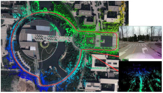
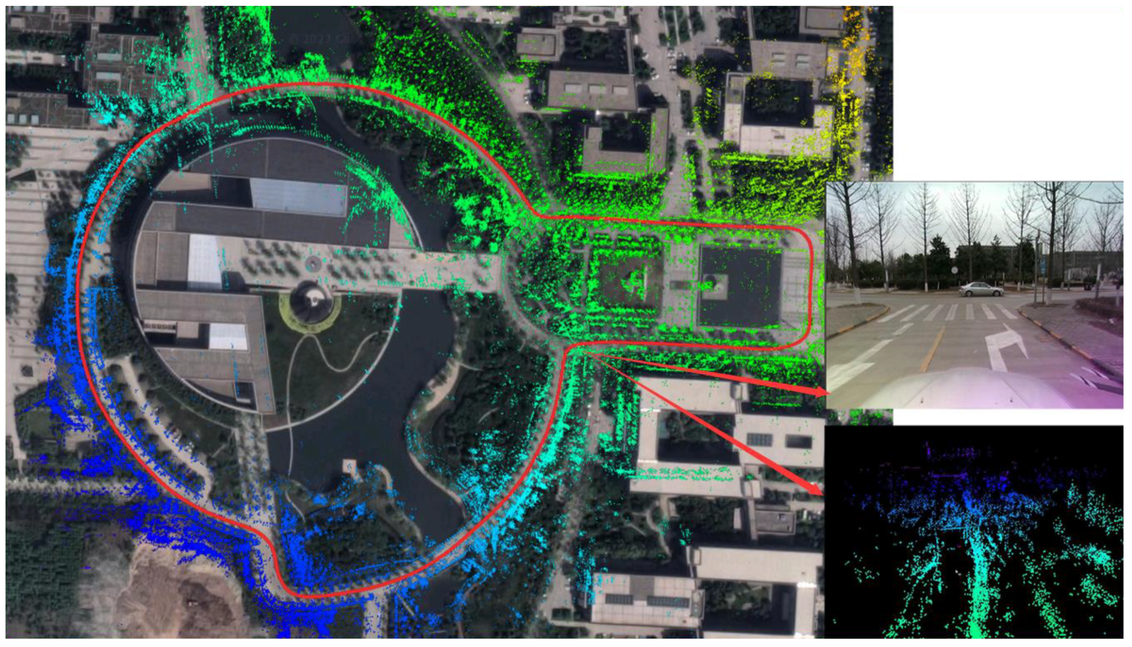
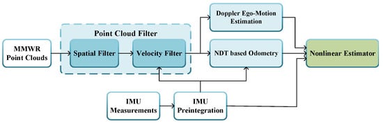
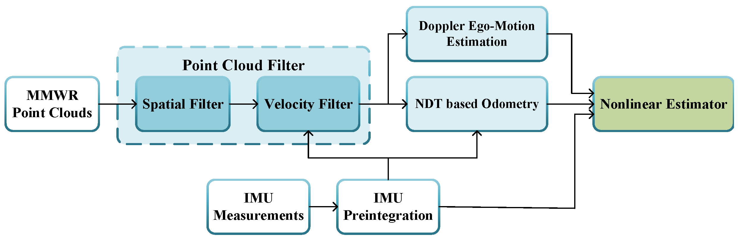
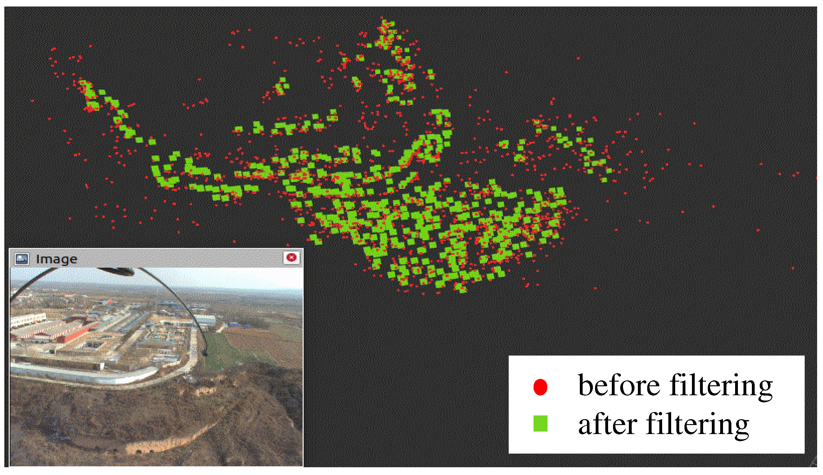
In this paper, we propose a Radar Inertial Odometry (RIO)-based on a long-range 4D radar system and an IMU, which facilitates autonomous mobile systems, such as unmanned vehicles and unmanned aerial vehicles, to localize themselves reliably in complex environments. An illustrative example of the proposed method in a large outdoor scene is shown in Figure 1. The framework is described in Figure 2. First, we design a point cloud preprocessing pipeline, which contains a spatial filter and a velocity filter to eliminate noisy points and outliers from moving objects. Afterward, the point clouds are used to estimate ego–motion velocities based on its Doppler measurement and to obtain an odometry measurement based on the Normal Distribution Transformation (NDT). The IMU data are preintegrated to provide prior information for the velocity filter and the NDT-based point cloud matching. Finally, the three measurements, namely the velocity, the odometry, and the IMU preintegration measurement, are factorized into a graph, and the poses of the robot are solved. The contributions of the paper are as follows:
Figure 1.
The 3D mapping results of radar SLAM in large outdoor scenes.
Figure 2.
Framework of the proposed RIO system.
- We developed a 4D long-range radar-based navigation frontend, which includes odometry and a velocity estimator to estimate the radar ego–motion.
- We built a backend estimator, which factorizes the radar odometry, Doppler velocities, and IMU measurement in a factor graph and solves the robot’s poses in a sliding window fashion.
- We extensively tested our framework in complex large-scale 2D/3D environments, including dynamic objects.
The rest of the paper is organized as follows. The related works are reviewed in Section 1. The radar odometry and radar inertial navigation system are given in Section 2 and Section 3, respectively. The experimental validations are provided in Section 4. We conclude the paper in Section 5.
In this section, we present the preprocessing steps of the 4D radar point cloud to obtain odometry measurement and ego–motion velocity. Initially, we give a simple but effective process to eliminate outliers; then, the odometry and Doppler velocity are obtained based on filtered point clouds.
2. Radar Odometry
In this section, we present the preprocessing steps of the 4D radar point cloud to obtain the odometry measurement and ego–motion velocity. Initially, we give a simple but effective process to eliminate outliers; then, the odometry and Doppler velocity are obtained based on filtered point clouds.
2.1. Point Cloud Filter
Affected by the sensor’s own characteristics and environmental interference, the measured point cloud data contain many outliers. The outliers make the pose estimation inaccurate and destroy the stability of the SLAM system. There are mainly two types of outliers in the 4D millimeter-wave radar data. The first type is clutter points from ground effects and multipath effects. The second type comes from dynamic object perception. We use two filters, namely the spatial filter and the velocity filter, to remove the two types of outliners.
2.1.1. Spatial Filter
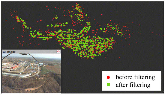
Ground effects and multipath effects are the main outlier resources in 4D millimeter radar perception data in a complex environment. Different from most normal radar points that belong to certain patterns, which reflect the structure of surrounding environments, the outliers are usually rather sparse and lack neighbor points. Based on this consideration, we implement a spatial filtering process that contains a pass-through filter and a radius outlier removal filter.
First, the pass-through filter is constructed by defining a pass-through space S originating from the center of radar as . A point measurement is an inlier when it belongs to S.
After that, all linear points are converted to 3D Cartesian coordinates for neighbored analysis. Given a point , its d neighborhood points set is defined as . An outlier can be defined when
The effect of using the above operations on radar point clouds is shown in Figure 3.
Figure 3.
The spatial filter effects on 4D radar measurement.
2.1.2. Point Cloud Filtering from Dynamic Targets
It is well known that moving objects may generate false motion estimation in the SLAM-based method. Removing the point cloud that belongs to the moving object is critical for localization in dynamic environments. Thanks to the Doppler effect, the points that belong to moving objects have obvious velocity differences. For a point i belonging to a static object, the following Equation (2) for the Doppler velocity and the radar ego–motion velocity is defined as follows:
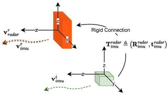
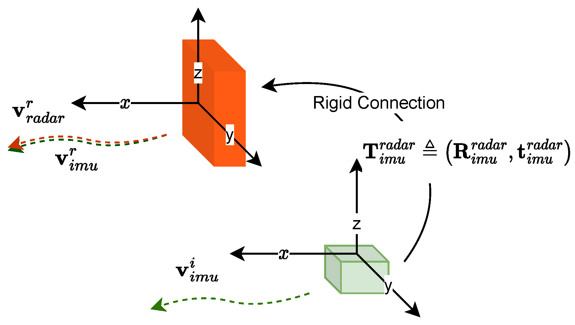
For a dynamic point, the above equation does not hold. Therefore, we use (2) to check points within a scan. As the true value is not known ahead, we turn to an IMU to acquire a guess of the ego–motion of the radar. We assume there is an IMU fixed to the body frame, and there is a rigid transformation between the radar and the IMU, , as shown in Figure 4. First, an ego–motion velocity of the IMU temporally that is aligned with the radar, which we denoted as , is obtained by preintegrating the IMU measurement data. Subsequently, the prior guess of the radar ego–motion in the radar local frame based on the IMU data, denoted as , is obtained by applying a constant transformation between the radar frame and the IMU frame, which is denoted as on . We replace with in (2) to check whether a point is static or not. Moreover, considering the uncertainties of the IMU preintegration and Doppler measurement, we can set a threshold to determine whether a point is an outlier as (3).
Figure 4.
The transformation relationship between and .
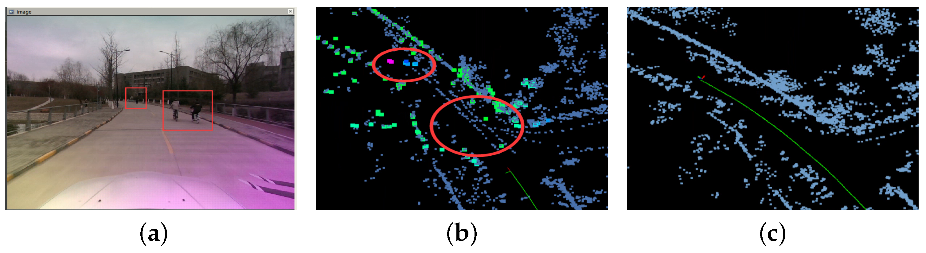
A demonstrative result of the radar odometry by removing velocity outliers is provided in Figure 5. As shown in Figure 5b, the moving objects (pedestrians) will cause unwanted trajectories in the map and will affect the localization as well. By filtering out the velocity outliers, more clear and more accurate localization can be obtained, as shown in Figure 5c.
Figure 5.
The filtering of moving objects. (a) Visuals captured pedestrians as moving objects. (b) Side-effect by wrongfully taking moving points. (c) Localization and mapping after velocity filtering.
2.2. NDT-Based Odometry
Point cloud registration is the main process for localization tasks. By registering between frames, the pose of the robot can be obtained incrementally. In this paper, we implement the Normal Distribution Transformation (NDT) method, which is known for its efficiency and tolerance to outliers [18]. The basic idea behind NDT is to represent a point cloud as a probability distribution and then to use statistical methods to match the distributions of two point clouds. Our registration goal is to calculate the pose transformation between millimeter-wave radar frames collected at consecutive time instances. Specifically, each point in the point cloud is assigned a Gaussian distribution with a mean and covariance matrix. The mean represents the location of the point, and the covariance matrix describes the uncertainty of the point’s location. The NDT algorithm then finds the transformation that minimizes the difference between the two probability distributions.
Given two point clouds and , each consisting of n points, the NDT algorithm seeks to find the transformation that best aligns with . The objective function to be minimized can be written as
where and are the translation and rotation components of the transformation , and are the ith and jth points in and , respectively, and is a weight function that determines the influence of the jth point in on the ith point in . The weight function is typically chosen to be a function of the distance between the mean of the Gaussian distributions assigned to the two points.
The optimization problem can be solved using gradient descent, where the gradient is given by
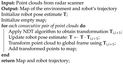
where and are the identity and zero matrices, respectively. The NDT algorithm can be used for SLAM by iteratively applying the algorithm to pairs of consecutive point clouds generated by the radar sensor. The transformation between each pair of point clouds can then be used to update the robot’s pose estimate and construct a map of the environment. The general flow of the algorithm is outlined in Algorithm 1 below.
| Algorithm 1: NDT-based SLAM algorithm |
 |
2.3. Doppler Ego–Motion Estimation
As one advantage over other sensors, such as LiDARs and RGBD cameras, radar provides radial velocity over the Doppler effect. The velocity of a 4D millimeter-wave radar can be obtained based on scanned points in each frame [19]. Multiple points with velocity measurement and position can be used to estimate the 3D velocity of the radar according to Equation (6).
Given n points with a radar scan, the above equation can be written as
The vector is the stacked s for all points from a radar point clouds scan. Then the least squares solution of can be obtained as
When the radar points contain outliers, using the results directly obtained from (8) may introduce errors. The abnormal values caused by noise can be further removed by a Random Sample Consensus (RANSAC) method, which was first proposed in [20] and has been demonstrated to be an effective method to remove noise and outliers in radar point clouds [21,22].
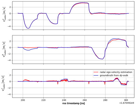
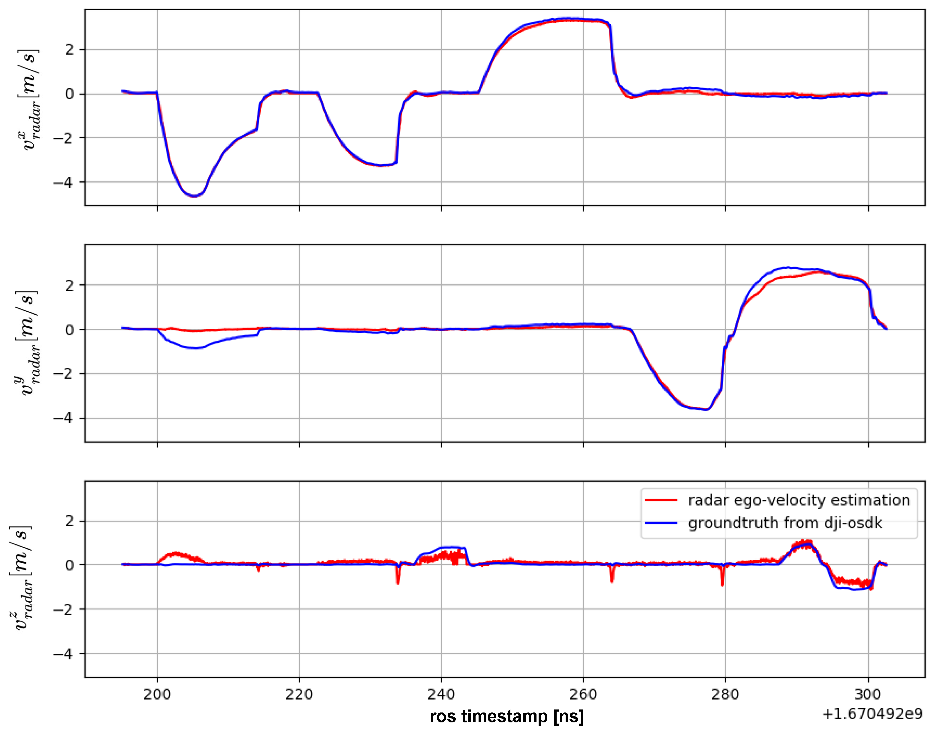
A test of the velocity estimation based on the above method against the RTK ground truth is provided in Figure 6. It can be seen that the error of ego–velocity estimation is within a reasonable range with RMSE 0.175 m/s. Because our millimeter-wave radar has a long detection distance of 300 meters, and the previous work has included the removal of outliers, we can also achieve more accurate velocity estimation in much more open areas.
Figure 6.
The 3D ego–motion velocity estimation compared to RTK ground truth from dji-osdk.
3. Nonlinear Estimator
3.1. Estimator Formulation
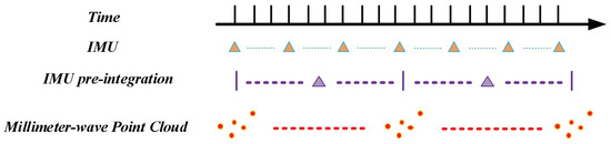
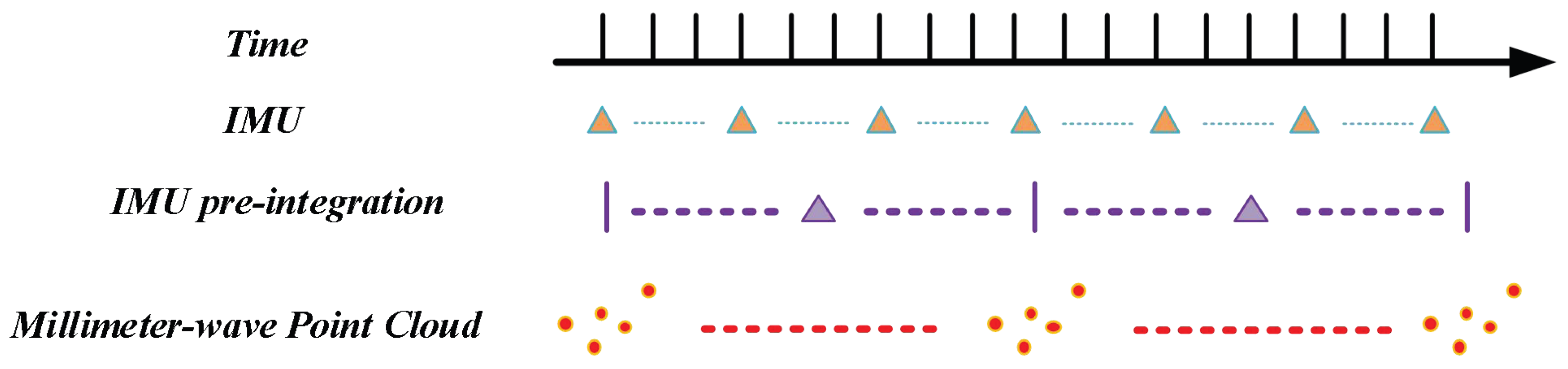
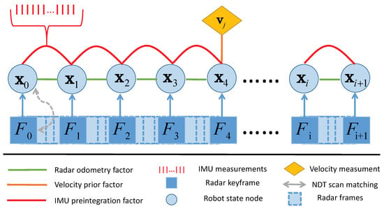
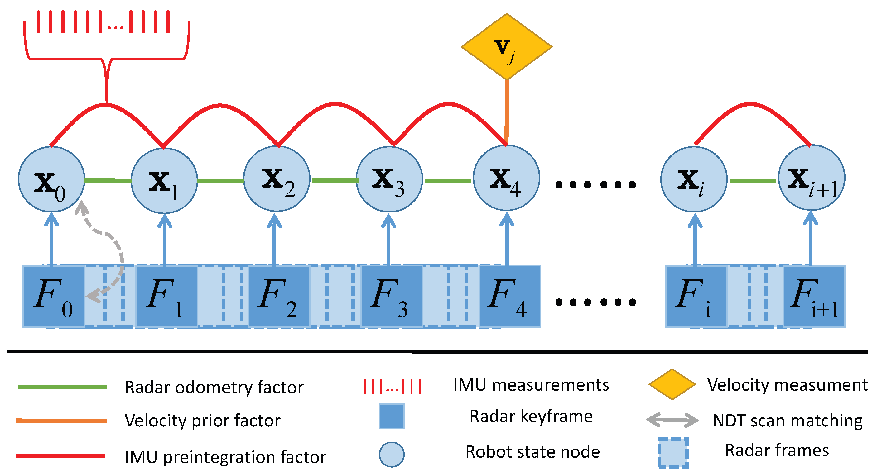
In this part, we aim at developing a nonlinear optimization-based framework to estimate the pose of a robot. Specially, we consider fusing the IMU measurement, radar odometry measurement, and velocity estimation in a sliding window fashion, as shown in Figure 7. The factor graph of our fusion scheme is shown in Figure 8. The states included in the sliding window at time t are defined as
where contains the active IMU states within the sliding window at time instance t. denotes the set of IMU measurements at t. The IMU state is
where is a unit quaternion that denotes the rotation from the global frame to the IMU frame . and are the IMU position and velocity, respectively. , are the random walk biases for the gyroscope and accelerator, respectively.
Figure 7.
Time alignment of sensor data.
Figure 8.
The factor graph of our RIO framework.
With the state definition (9), the objective is to minimize the cost function of different measurement residuals in (11).
The first term is the cost of IMU-based residual, and defines the measurement residual between the active frames m and . The IMU samples consist of all IMU frames between adjacent radar active frames; thus, the preintegration of the IMU samples is not dependent on a fixed time step but rather determined by the time interval between radar active frames. The second term is the cost of odometry residuals, and the last term is the cost of the velocity residuals. and are the set of measurements within the sliding window at time t. and are the covariance of the two measurements. The optimization of (11) is usually solved with an iterative least squares solver through a linear approximation. In this paper, we formulate and solve the problem based on the GTSAM package [23].
3.2. Factorization
In this part, the three information sources, namely the IMU, radar odometry, and radar velocity, are factorized.
3.2.1. IMU Preintegration Factor
The error term incorporates the relative motion constraints between radar keyframes. IMU measurements between m and are preintegrated as in [24], and the residual term at m is defined as
where is the preintegrated IMU measurements incorporating gyroscope and accelerometer readings from keyframe m to . is the time interval between keyframes. The operator is to extract the vector part of a quaternion. More details on the preintegration can be found in [24].
3.2.2. Odometry Factor
The odometry factor relates the consecutive measurements of millimeter-wave radar data to calculate the robot’s motion between two poses. Given the odometry observation between as , , the odometry residual is calculated as
where ∘ denotes the quaternion multiplication operator. The detailed construction of the factor is given in [25] and is omitted here due to space limitation.
3.2.3. Velocity Prior Factor
These factors constrain the estimate of the robot’s velocity to improve the robustness of SLAM. Let be a prior velocity estimate which comes from the output of the radar ego–velocity estimator described in Section 2.3, and the velocity residual can be simply formulated as
where is the estimated velocity.
4. Experiment Results
In this section, we validate our proposed RIO in complex environments. Especially, the experiments are carried out in both 2D environments with a vehicle and 3D environments with a quadrotor UAV.
4.1. Experiment Setups
4.1.1. System Setups
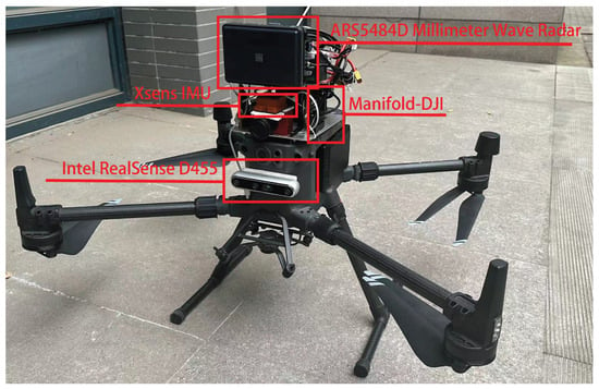
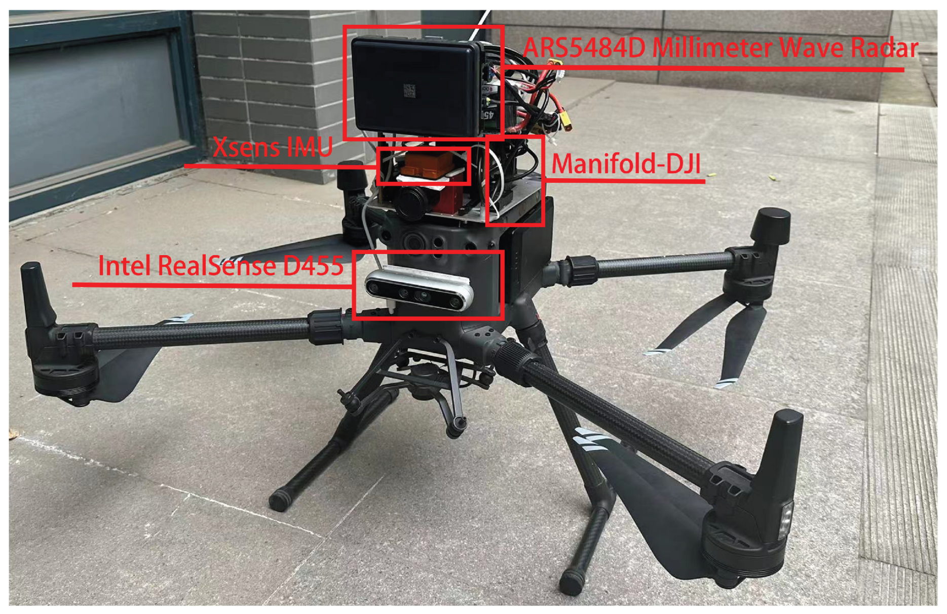
In the experiment, we use a Continental ARS5484D radar as the main perception sensor, which is a long-range millimeter-wave radar that has a 300 m maximum sensing range, and the FOV is a 120° azimuth angle and 30° elevation angle. In addition, we use an Xsense IMU to measure the local motion of the platform. For comparison purposes, we use a D455 camera to carry out vision-based localization algorithms. The RTK positioning information from the DJI M300 UAV navigation system is used as the ground truth. A DJI Manifold-2C is used to record the sensor data and ground truth. The detailed setup is illustrated in Figure 9.
Figure 9.
Experimental equipment.
4.1.2. Experimental Environments
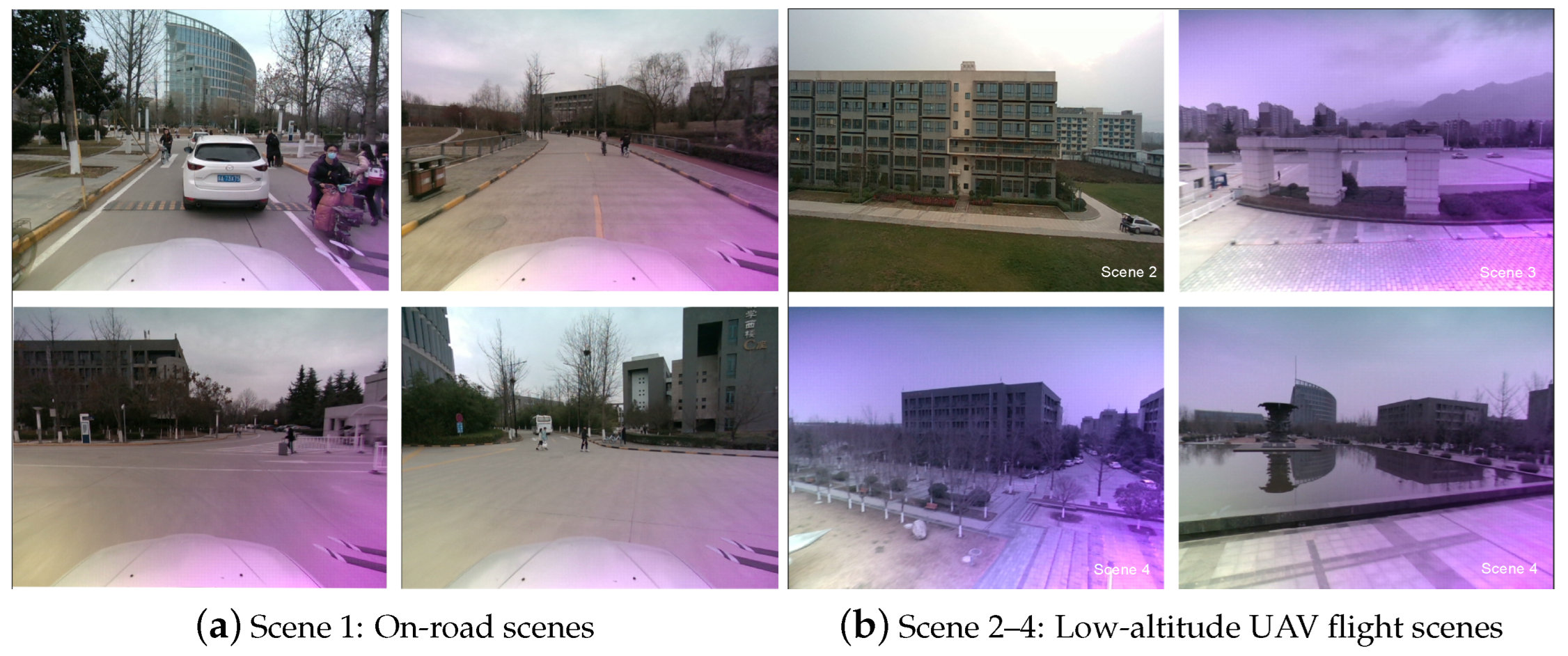
As we intended to implement the proposed method in a large-scale environment, we carried out experimental tests in two environment categories, which were (1) an on-road experiment by carrying the UAV on a vehicle, and (2) an in-the-air experiment by flying the UAV in a low-altitude environment with dense objects. The experiment environments are shown in Figure 10.
Figure 10.
Experimental environment.
4.1.3. Metrics
The effectiveness of our method is based on two metrics, the Relative Pose Error (RPE) and the Absolute Pose Error (APE), which are carried out based on the EVO toolbox [26]. The RPE metric is used to evaluate the relative error between the estimated and ground truth poses over time. It is calculated by computing the difference between the estimated pose and the ground truth pose at each time step and then computing the Root Mean Squared Error (RMSE) of these differences over the entire trajectory. On the other hand, the APE metric is used to evaluate the absolute error between the estimated and ground truth poses at a specific time step. It is calculated by computing the Euclidean distance between the estimated position and orientation and the ground truth position and orientation at a given time step.
4.2. Experiment Analysis
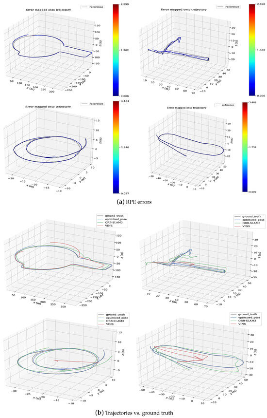
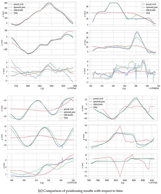
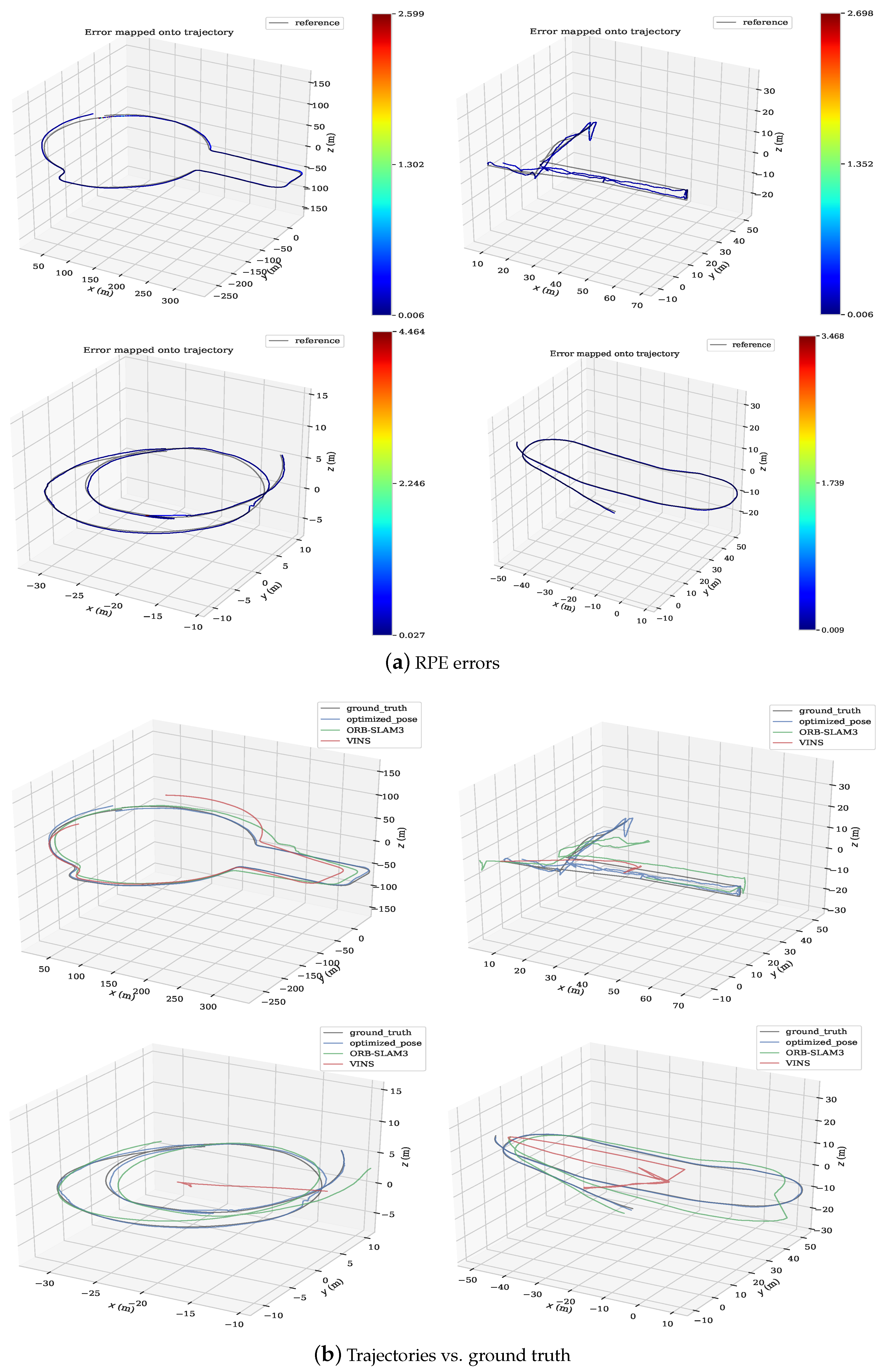
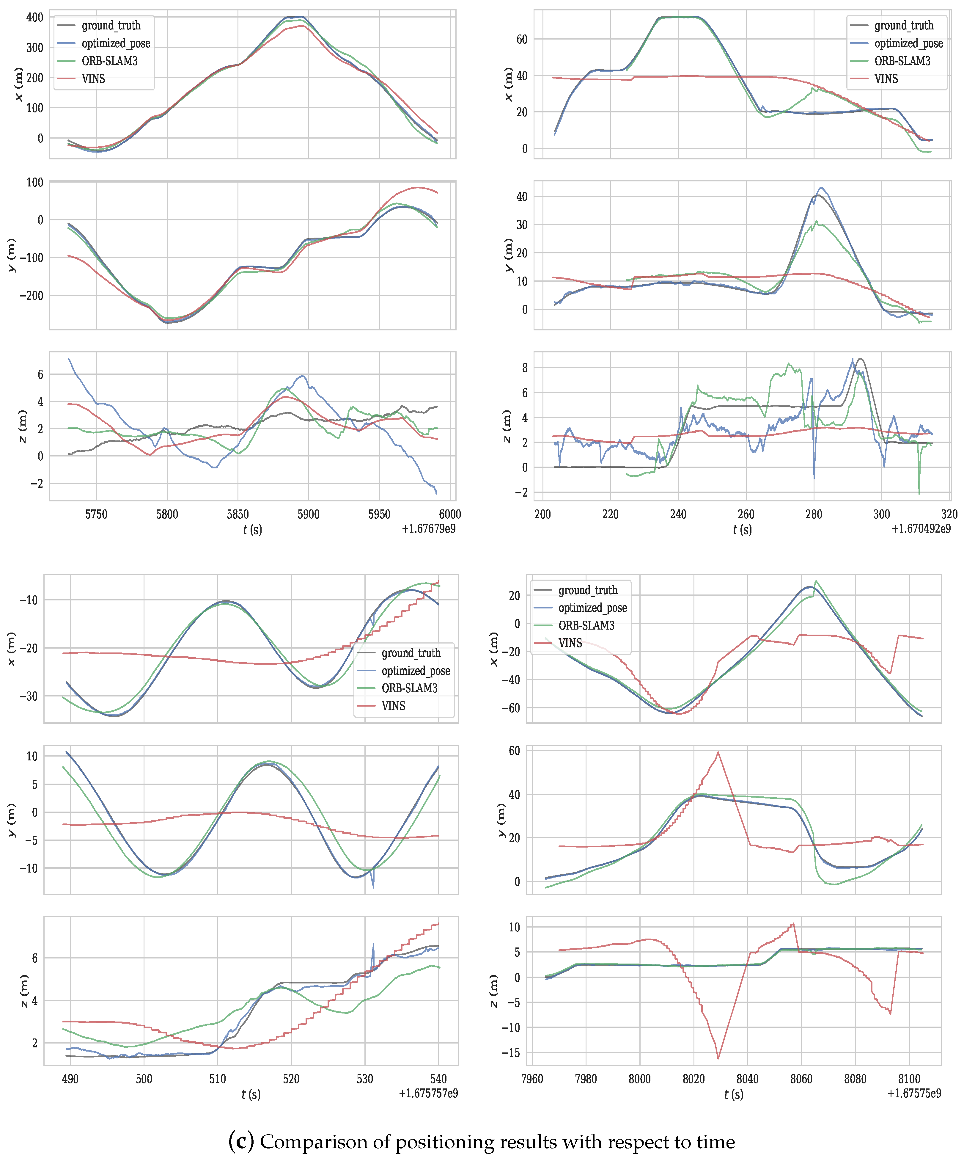
We evaluated our proposed RIO with four scenes in the above two types of environments. Scene 1 is the on-road test in a large campus environment, and Scenes 2–4 are in-the-air tests. In Figure 11, we stipulate that each subfigure’s top left, top right, bottom left, and bottom right correspond to Scene 1, 2, 3, and 4, respectively. The RPE and APE results of our methods are provided in Table 1 and Table 2, respectively. Additionally, we provide the RPE of our method in Figure 11a. Apparently, the results indicate that the accuracy of our proposed RIO was within the acceptable level of error, with RPE errors below 0.5.
Figure 11.
Experiment results of Scene 1–4.
Table 1.
RPE evaluation results [m].
Table 2.
APE evaluation results [m].
To further demonstrate the effectiveness of our proposed method, we further carried out the localization using two vision-based methods, namely the VINS-Mono and ORB-SLAM3. The results show that the environment and highly aggressive maneuverability of the platform were quite challenging for vision-based navigation systems. The comparative results of our methods and the two vision-based localization methods are plotted in Figure 11. Specifically, Figure 11b show the estimation trajectories based on different methods. Figure 11c shows the trajectories with respect to time. (b) and (c) indicate that the two vision-based methods failed to achieve reliable localization in in-the-air 3D environments due to the aggressive motion of the UAV. In Scene 1, all methods were able to provide estimation results. Among them, our method could achieve the best localization performance.
5. Conclusions
Millimeter-wave radar provides more robust sensing in harsh conditions. In this paper, we proposed a radar inertial odometry framework using a 4D millimeter-wave radar. First, by analyzing the strengths and weaknesses of the point cloud generated by the 4D millimeter-wave radar, the point cloud was preprocessed to remove noise, thereby allowing for the estimation of the robot’s relative transformation through interframe point cloud registration. Then, we proposed a graph-based SLAM framework that fuses the velocity information from the IMU data, millimeter-wave radar odometry, and velocity estimation module. Our proposed method was extensively tested in challenging environments, including changing weather conditions, dynamic targets, and various platforms. The results show that the proposed SLAM framework can provide reliable localization for mobile platforms such as vehicles and drones under various operating conditions. In the future, we will investigate the environmental factors that affect localization performance and also the fusion of multimodality fusion-based methods.
Author Contributions
Conceptualization, Y.L. and C.Z.; methodology, L.H., Y.L. and X.L.; software, L.H.; validation, J.W. All authors have read and agreed to the published version of the manuscript.
Funding
This research was funded by National Natural Science Foundation of China under Grant 62203358, Grant 62233014, and Grant 62073264.
Data Availability Statement
The source code and recorded experimental data sets are available at https://github.com/lincoln1587/radar-inertial-odometry (accessed on 3 May 2024).
Conflicts of Interest
The authors declare no conflicts of interest.
References
- Barfoot, T.D. State Estimation for Robotics; Cambridge University Press: Cambridge, UK, 2017. [Google Scholar]
- Mur-Artal, R.; Montiel, J.M.M.; Tardos, J.D. ORB-SLAM: A versatile and accurate monocular SLAM system. IEEE Trans. Robot. 2015, 31, 1147–1163. [Google Scholar] [CrossRef] [Scilit]
- Forster, C.; Pizzoli, M.; Scaramuzza, D. SVO: Fast semi-direct monocular visual odometry. In Proceedings of the 2014 IEEE International Conference on Robotics and Automation (ICRA), Hong Kong, China, 31 May–7 June 2014; IEEE: Piscataway, NJ, USA, 2014; pp. 15–22. [Google Scholar]
- Zhang, J.; Singh, S. LOAM: Lidar odometry and mapping in real-time. In Proceedings of the Robotics: Science and Systems, Berkeley, CA, USA, 12–16 July 2014; Volume 2, pp. 1–9. [Google Scholar]
- Yi, S.; Lyu, Y.; Hua, L.; Pan, Q.; Zhao, C. Light-LOAM: A Lightweight LiDAR Odometry and Mapping based on Graph-Matching. IEEE Robot. Autom. Lett. 2024, 9, 3219–3226. [Google Scholar] [CrossRef] [Scilit]
- Qin, T.; Li, P.; Shen, S. Vins-mono: A robust and versatile monocular visual-inertial state estimator. IEEE Trans. Robot. 2018, 34, 1004–1020. [Google Scholar] [CrossRef] [Scilit]
- Shan, T.; Englot, B.; Meyers, D.; Wang, W.; Ratti, C.; Rus, D. Lio-sam: Tightly-coupled lidar inertial odometry via smoothing and mapping. In Proceedings of the 2020 IEEE/RSJ International Conference on Intelligent Robots and Systems (IROS), Las Vegas, NV, USA, 24 October 2020–24 January 2021; IEEE: Piscataway, NJ, USA, 2020; pp. 5135–5142. [Google Scholar]
- Kasper, A.; Xue, Z.; Dillmann, R. The KIT object models database: An object model database for object recognition, localization and manipulation in service robotics. Int. J. Robot. Res. 2012, 31, 927–934. [Google Scholar] [CrossRef] [Scilit]
- Lyu, Y.; Nguyen, T.M.; Liu, L.; Cao, M.; Yuan, S.; Nguyen, T.H.; Xie, L. SPINS: A structure priors aided inertial navigation system. J. Field Robot. 2023, 40, 879–900. [Google Scholar] [CrossRef] [Scilit]
- Lyu, Y.; Yuan, S.; Xie, L. Structure Priors Aided Visual-Inertial Navigation in Building Inspection Tasks with Auxiliary Line Features. IEEE Trans. Aerosp. Electron. Syst. 2022, 58, 3037–3048. [Google Scholar] [CrossRef] [Scilit]
- Lyu, Y.; Cao, M.; Yuan, S.; Xie, L. Vision-Based Plane Estimation and following for Building Inspection with Autonomous UAV. IEEE Trans. Syst. Man Cybern. Syst. 2023, 53, 7475–7488. [Google Scholar] [CrossRef] [Scilit]
- Hong, Z.; Petillot, Y.; Wallace, A.; Wang, S. RadarSLAM: A robust simultaneous localization and mapping system for all weather conditions. Int. J. Robot. Res. 2022, 41, 519–542. [Google Scholar] [CrossRef] [Scilit]
- Kim, G.; Park, Y.S.; Cho, Y.; Jeong, J.; Kim, A. Mulran: Multimodal range dataset for urban place recognition. In Proceedings of the 2020 IEEE International Conference on Robotics and Automation (ICRA), Paris, France, 31 May–31 August 2020; IEEE: Piscataway, NJ, USA, 2020; pp. 6246–6253. [Google Scholar]
- Burnett, K.; Schoellig, A.P.; Barfoot, T.D. Do We Need to Compensate for Motion Distortion and Doppler Effects in Spinning Radar Navigation? IEEE Robot. Autom. Lett. 2021, 6, 771–778. [Google Scholar] [CrossRef] [Scilit]
- Lim, H.; Han, K.; Shin, G.; Kim, G.; Hong, S.; Myung, H. ORORA: Outlier-Robust Radar Odometry. arXiv 2023, arXiv:2303.01876. [Google Scholar]
- Kramer, A.; Harlow, K.; Williams, C.; Heckman, C. ColoRadar: The direct 3D millimeter wave radar dataset. Int. J. Robot. Res. 2022, 41, 351–360. [Google Scholar] [CrossRef] [Scilit]
- Zhuang, Y.; Wang, B.; Huai, J.; Li, M. 4D iRIOM: 4D Imaging Radar Inertial Odometry and Mapping. IEEE Robot. Autom. Lett. 2023, 8, 3246–3253. [Google Scholar] [CrossRef] [Scilit]
- Biber, P.; Strasser, W. The normal distributions transform: A new approach to laser scan matching. In Proceedings of the 2003 IEEE/RSJ International Conference on Intelligent Robots and Systems (IROS 2003) (Cat. No.03CH37453), Las Vegas, NV, USA, 27–31 October 2003; Volume 3, pp. 2743–2748. [Google Scholar] [CrossRef] [Scilit]
- Doer, C.; Trommer, G.F. An EKF Based Approach to Radar Inertial Odometry. In Proceedings of the 2020 IEEE International Conference on Multisensor Fusion and Integration for Intelligent Systems (MFI), Karlsruhe, Germany, 14–16 September 2020; pp. 152–159. [Google Scholar] [CrossRef] [Scilit]
- Fischler, M.A.; Bolles, R.C. Random sample consensus. Commun. ACM 1981, 24, 381–395. [Google Scholar] [CrossRef] [Scilit]
- Kellner, D.; Barjenbruch, M.; Klappstein, J.; Dickmann, J.; Dietmayer, K. Instantaneous ego-motion estimation using doppler radar. In Proceedings of the 16th International IEEE Conference on Intelligent Transportation Systems (ITSC 2013), The Hague, The Netherlands, 6–9 October 2013; IEEE: Piscataway, NJ, USA, 2013; pp. 869–874. [Google Scholar]
- Park, Y.S.; Shin, Y.S.; Kim, J.; Kim, A. 3d ego-motion estimation using low-cost mmwave radars via radar velocity factor for pose-graph slam. IEEE Robot. Autom. Lett. 2021, 6, 7691–7698. [Google Scholar] [CrossRef] [Scilit]
- Dellaert, F. Factor Graphs and GTSAM: A Hands-On Introduction; Technical Report; Georgia Institute of Technology: Atlanta, Georgia, 2012. [Google Scholar]
- Forster, C.; Carlone, L.; Dellaert, F.; Scaramuzza, D. On-manifold preintegration for real-time visual–inertial odometry. IEEE Trans. Robot. 2016, 33, 1–21. [Google Scholar] [CrossRef] [Scilit]
- Nguyen, T.M.; Cao, M.; Yuan, S.; Lyu, Y.; Nguyen, T.H.; Xie, L. Viral-fusion: A visual-inertial-ranging-lidar sensor fusion approach. IEEE Trans. Robot. 2021, 38, 958–977. [Google Scholar] [CrossRef] [Scilit]
- Grupp, M. Evo: Python Package for the Evaluation of Odometry and SLAM. 2017. Available online: https://github.com/MichaelGrupp/evo (accessed on 3 May 2024).


Disclaimer/Publisher’s Note: The statements, opinions and data contained in all publications are solely those of the individual author(s) and contributor(s) and not of MDPI and/or the editor(s). MDPI and/or the editor(s) disclaim responsibility for any injury to people or property resulting from any ideas, methods, instructions or products referred to in the content. |
© 2024 by the authors. Licensee MDPI, Basel, Switzerland. This article is an open access article distributed under the terms and conditions of the Creative Commons Attribution (CC BY) license (https://creativecommons.org/licenses/by/4.0/).