Corrosion Behaviour of Dual-Phase High Carbon Steel—Microstructure Influence


Centre for Sustainable Materials Research and Technology (SMaRT Centre), School of Materials Science and Engineering, The University of New South Wales (UNSW Sydney), Sydney, NSW 2052, Australia
*
Author to whom correspondence should be addressed.
J. Manuf. Mater. Process. 2017, 1(2), 21; https://doi.org/10.3390/jmmp1020021
Submission received: 9 October 2017
/
Revised: 20 November 2017
/
Accepted: 20 November 2017
/
Published: 24 November 2017
Abstract
:Dual-phase high carbon steel is widely used in mining and in chemical industry applications in highly abrasive environments due to its excellent hardness and abrasion resistance. In recent years, the use of less expensive but more corrosive solutions in industrial processes has become more common. As a result, detailed understanding of the corrosion behaviour of dual-phase high carbon steel is needed; an issue that has, to date, been little-studied. This study investigates in detail the corrosion behaviour of dual-phase high carbon steel in a sodium chloride solution at different times, at the macro- and nano-scale, using various techniques. Using scanning electron microscopy (SEM) and 3D laser-scanning confocal microscopy, the corrosion behaviour of this important industrial steel was investigated at the micro-scale, then by using atomic force microscopy (AFM) it was further investigated at the nano-scale. The results reveal preferential corrosion attack on the retained austenitic phase, rather than the martensite phase, which is due to the carbon partitioning between martensite and austenite in this grade of steel.
1. Introduction
Despite the proliferation of new, advanced materials, high-carbon low-alloyed steel remains one of the most attractive metals for high-abrasion environments, due to its superior properties and hardness and relative low cost of production. Dual-phase high-carbon steel consists of martensite and retained austenite structures that offers excellent toughness [1], hardness, and abrasion resistance, making it suitable for extreme operating conditions [2] and environments [3]. Besides a comprehensive understanding of these excellent mechanical properties, we need to similarly understand the corrosion mechanism/s and the behaviour of the constituent phases of dual-phase steels if we are to effectively evaluate their real potential for many applications [4]. Although Bani et al. [5] and Makarenko et al. [6] have investigated the effect of microstructures on the corrosion resistance of low carbon steels; there has been little such investigation of dual-phase high-carbon steels. Understanding the corrosion mechanism and behaviour of these steels in corrosive media is crucial for identifying new applications.
Steel with a carbon content of more than 0.6 wt % is classified as high carbon steel. Increasing the carbon percentage increases the corrosion resistance, but further studies are required to identify the influence of dual-phase morphology on the corrosion behaviour of high-carbon steels. The martensite microstructures offer excellent strength and hardness properties compared to the austenitic phase. Therefore, increasing the martensite phase and reducing the presence of austenite improves the strength and hardness of the steel [7]. However, austenite provides good ductility and energy absorption. Besides a favourable combination of mechanical properties, an extensive knowledge of corrosion behaviour of dual-phase high carbon steel is important for determining the real potential of these steels in highly abrasive and corrosive applications. Having different phases in steel, such as martensitic phase, which has high internal energy, or retained austenite, which is metastable at room temperature, make the steel vulnerable to corrosion. On the other hand, it is well known that the presence of carbon in solid solution influences the corrosion resistance properties of steel [7].
The retained austenite phase in this high carbon steel is a meta-stable phase, which can be transferred to a martensitic structure if the required energy is provided [1]. Recent study by Rumana et al. has demonstrated that the percentage of carbon in austenitic phase is lower than carbon in martensitic phase in dual-phase high carbon steel [8,9], this means that the corrosion mechanism can be initiated from either the retained austenite or martensite phase.
Further investigation is needed to determine the influence of dual-phase morphology on the corrosion-resistance properties of this new emerging grade of steel. The aim of this study is to investigate the corrosion mechanism of dual-phase high carbon steel in 0.5 M NaCl, in respect to the different phases and influence of each phase on corrosion behaviour. Our results showed that the retained austenite phase was preferentially corroded in this dual-phase high carbon steel.
2. Experimental
2.1. Material Preparation
Dual-phase high carbon steel with a chemical composition of 0.98% C, 0.97% Mn, 0.63% Cr and a martensite structure with an average of 30% retained austenite [1] was used in this study. Samples were cut to dimensions of 6 mm × 6 mm × 3 mm using a low-abrasion cutting rate. The samples were then carefully mounted ground and polished with low force using Struers Labopol-5 to a mirror finish to avoid microstructural changes due to applied shear. The density of the sample was measured using Micromeritics AccuPyc-II 1340 Gas Pycnometer. Three samples were used, and an average density was calculated. The weight of each sample was measured with a precision laboratory scale, Precisa 1212 M-SCS. By mixing chemical-grade NaCl and distilled water, the 0.5 M NaCl solution was prepared and the samples were immersed into the solution for 1 h, 2 h, 6 h, 12 h, 24 h and 48 h at room temperature (24 ± 1 °C). Following immersion, samples were cleaned with an ultrasonic cleaner to exclude any corrosion products on the surface of the samples, and then they were dried completely before further investigation.
2.2. Analytical Methods
Microstructural changes during corrosion were investigated with a Hitachi S3400 SEM, and surface roughness during corrosion in micron scale was measured by non-contact three-dimensional imaging using a Keyence VK-X250 3D LSCM. This 3D Laser-Scanning Confocal Microscope (3D LSCM) instrument is equipped with non-contact profilometry and multilayer laser systems, offering 3D imaging with superior colour saturation and various line scan profile measurements [10]. It also provides a larger scan area up to micro-scale resolution, and thus, better overall mean roughness average (Ra) and root mean square roughness (Rq) values. Atomic Force Microscope (AFM) analysis was carried out with a Bruker Dimension ICON SPM, which is equipped with ScanAsyst-Air fitted and a silicon-coated tip in the PeakForce and TappingMode modes. Surface roughness as a function of corrosion time in an area of 5μm × 5μm was scanned for, at a scan rate of 0.349 Hz, to optimise resolution and accuracy. The AFM provides high-precision three-dimensional topographical imaging [11,12,13] suitable for surface morphology analysis at nano-scale reconstruction [14].
3. Results and Discussions
3.1. Dual-Phase Microstructures
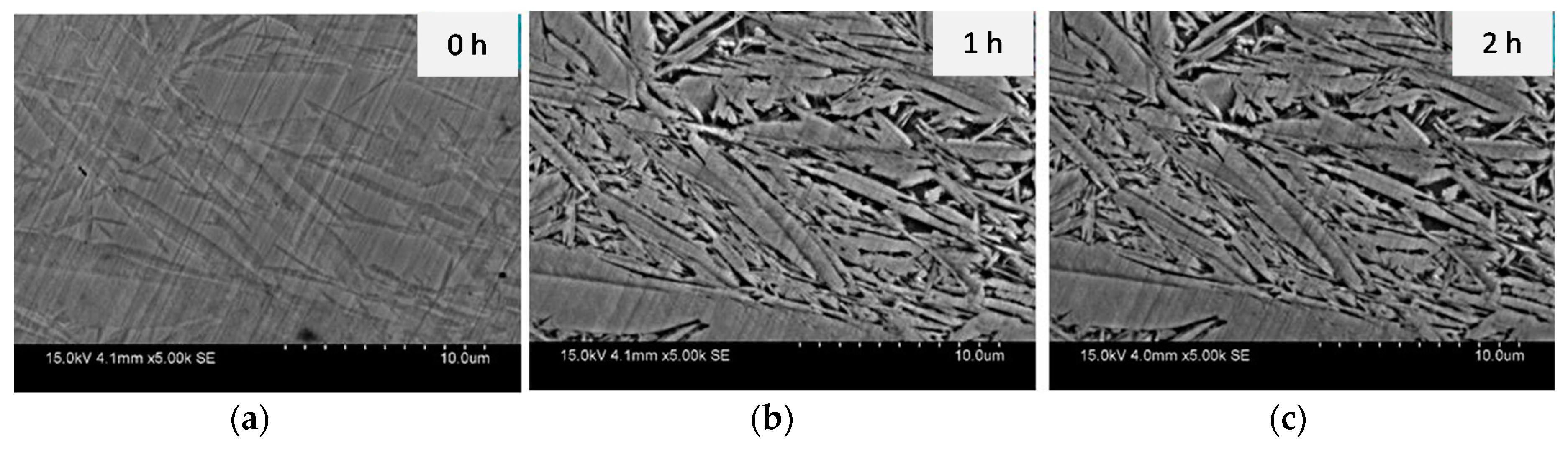
The microstructure of the slightly etched sample is shown in Figure 1; at t = 0 h, a dual-phase morphology is visible under SEM analysis, the light grey area in Figure 1a is martensite phase and the dark grey area is austenite. In order to see different phases for starting samples at t = 0 h, the samples were etched using a 2% nital solution. The sample was immersed in the corrosive solution for up to one hour, and the results revealed a preferential attack on the austenite phase as its microstructure was corroded more than martensitic phase, the black phase in Figure 1b,c is corroded austenite phase, and the grey area is the martensite phase. This phenomenon, in which the martensite was able to resist the sodium chloride attack and damage was confined to the retained austenite phase, occurred up until two hours of immersion. This means that the martensite phase was more stable in the face of corrosion attack over this time period, as the amount of carbon present in the martensitic phase is higher than in the retained austenitic phase [8].
The evidence of corrosion and amount of retained austenite degradation due to the preferential attack on the retained austenite was detected using weight-loss measurements. Weight was 7.501 × 10⁻³% and 1.250 × 10⁻²% at the end of the first and second hour, respectively. These results indicate the corrosion attack follows a non-linear behaviour, as more corrosion occurred in the first hour than in the second hour.
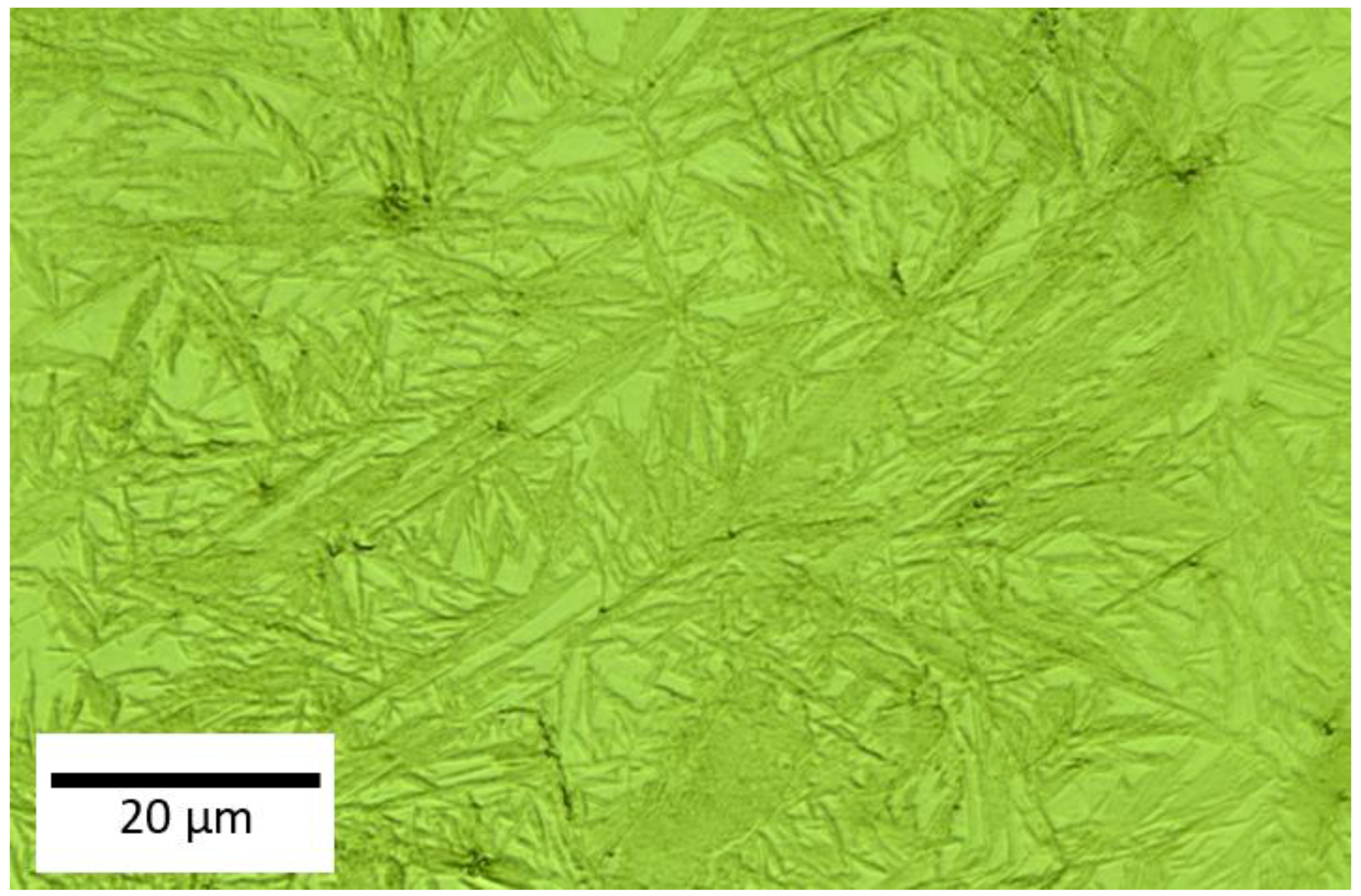
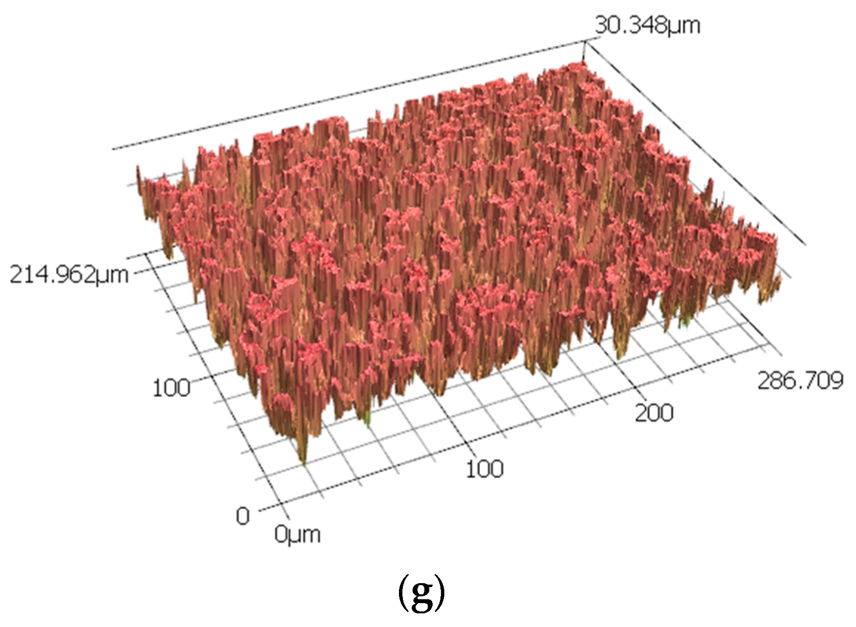
Further topography images were analysed using a 3D LSCM, which provides roughness profiles; Figure 2 shows the surface of the sample before corrosion. This is clearly indicates the dual phase structure in this steel. As this technique combines a minimum scale of micro-resolution with a laser technology system, non-contact measurement can be conducted, as presented in Figure 2. Consequently, it addressed the overall corrosion behaviour on the dual-phase high carbon steel using micro-scale reconstruction imaging. The dual-phase martensite and retained austenite were visible in this three-dimensional model analysis, as presented in Figure 3 for different corrosion times. The austenite structure was seen loosening its shape as the corrosion products began to appear over time. The disappearance of the austenitic phase continued until the outer surface started to become rougher. Some weaker areas, which are mostly the grain boundaries between retained austenite and martensite, were not able to retain their original shape, and pit holes began to form, moving from the exterior into the interior of the steel surface. This pitting corrosion characterised the nature of the corrosion attack, although there were variations, with some regions being more corroded, and others being more resistant, resulting in less severe corrosion damage. These pits were varied in size, and were formed from the retained austenite areas, as these were preferentially consumed as they did not contain as much carbon as the martensite areas. As has been shown by 3D imaging of the sample in Figure 3, at the 24 h corrosion the pitting depth was around 215 microns.
In these micro-scale high-resolution images, micron-sized pits are visible. The larger pit sizes can be more accurately observed by 3D LSCM. Reasonable averages of surface roughness for Ra and Rq, including the corresponding pit distribution, were obtained by scanning an area of 215 × 287 μm; the results are summarised in Table 1.
3.2. Corrosion Behaviour
The plotted graph shows the weight loss measurements using high-precision laboratory scales, making it feasible to measure the degradation process of the dual-phase microstructure of the high carbon steel in relation to specific times (of exposure to corrosive attack), as shown in Figure 4. Two different stages were identified. In Stage 1, covering the first two hours, significant weight loss occurred initially, as the austenite phase began to corrode, followed by a little degradation of the martensite phase in the sodium chloride solution. Over this period, corrosion products and pit holes began to form. Stage 2, the longer time frame up to 48 h, indicated a more gradual loss of weight, as both phases corroded simultaneously, but at different rates. This phenomenon was further confirmed in the nano-scale analysis with AFM. The data were fitted with a second-order polynomial function to acquire the weight loss of the sample as a function of time. In addition, the expression of corrosion rate can be calculated in other ways, in which all of those functions are related to Faraday’s Law; decrease of sample thickness over the time, material loss by surface unit as a function of time, or intensity of localised corrosion by surface unit [15]. The effect of the different carbon percentages and variations in the boundary structures between the retained austenite and martensite interfaces can lead to unequal corrosion rates in dual-phase steels.
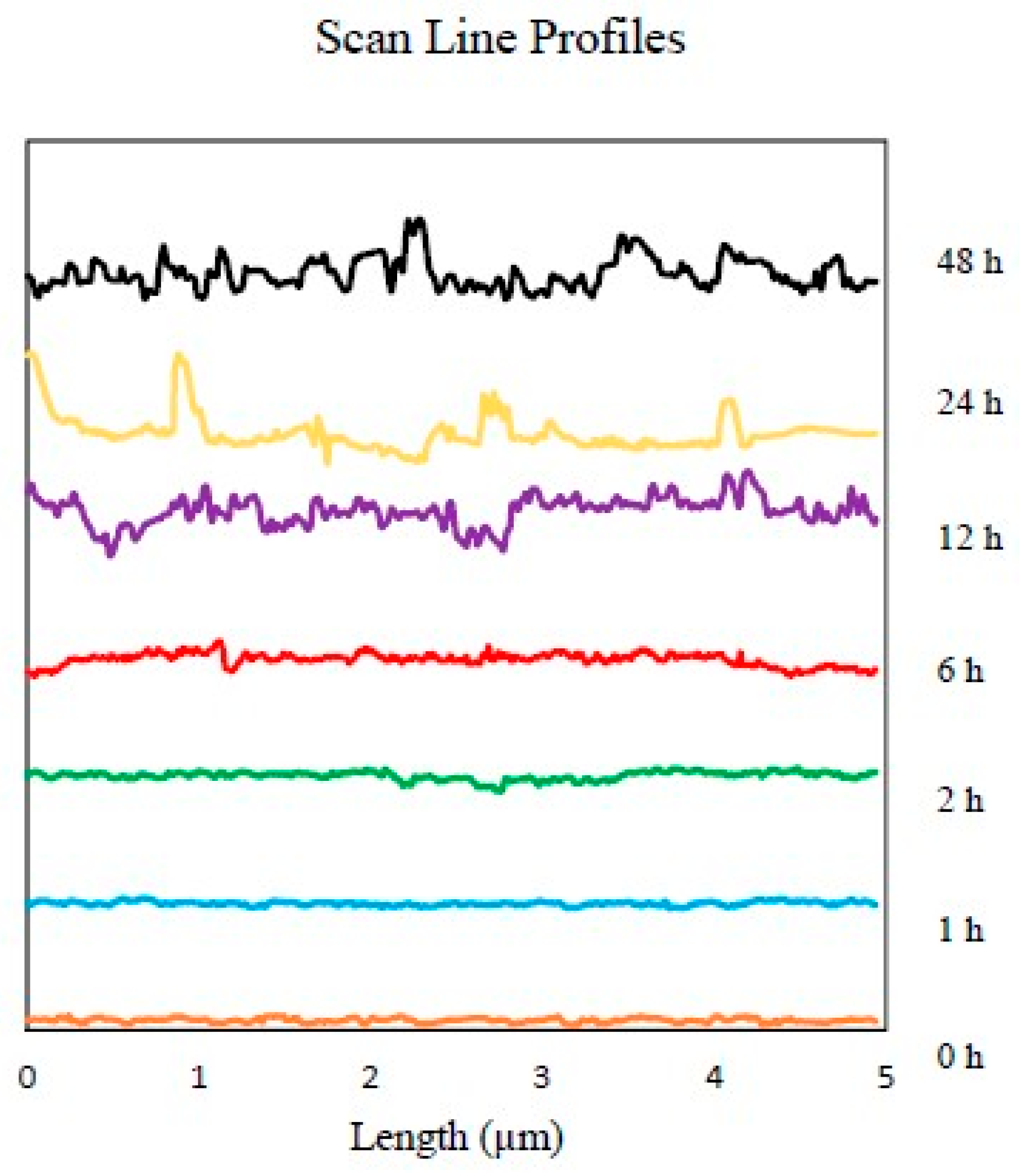
An insight into the corrosion at the nano-scale was obtained, as indicated in Figure 5. This shows the different AFM topography images of high carbon steel’s surface from 0 h to 48 h following immersion in the 0.5 M NaCl media. The seven three-dimensional high-reconstruction mappings shown in Figure 5 include quantitative data that is useful in tracking the evolution of the sample’s surface. Figure 5a represents the scan (t = 0 h) before contact with NaCl solution; as grain structures and polishing scratches were clearly observable, it was clear that the steel surface had not yet been transformed or modified by the corrosive solution. In Figure 5b, when t = 1 h, the original scratches were barely visible, and the steel surface’s had become coarser, as the austenite phase had started to corrode. By contrast, the martensite stayed intact and epitaxial oxides grew on the rougher area. The continuous corrosion attack was responsible for the unique appearance of the surface, as the original phase of austenite began to collapse, generating more pitting holes, and the martensite phase started to deteriorate; see Figure 5c. After the first two hours of the experiment, more of the austenite phase was consumed, causing an increase in surface roughness, as shown in Figure 5d. Both austenite and martensite were corroded, and a more uniform surface roughness was generated by around t = 12 h. This cyclical process continued until t = 48 h. The different topographies of the dual-phase high carbon steel are shown in Figure 5e–g. The AFM image offers more precise details, as well as various useful quantitative information, e.g., roughness average (Ra), root mean square roughness (Rq), and average maximum height of the profile (Rz). This valuable quantitative data regarding the evolution of the surface of the steel is summarised in the profiles of the line scans of each topography image, as presented in Figure 6, with a uniform gap to prevent redundant overlapping.
This study has demonstrated that the presence two phases in this type of steel was not only beneficial for improving mechanical properties, but also improved the steel’s resistance to corrosion. As these dual-phase microstructures have relatively similar chemical configurations, they do not promote corrosion due to their potential difference, unlike other dual-phase structures with different chemical compositions. At the same time, this investigation revealed that the presence of carbon in the form of solid solution of martensite with a sufficient volume fraction reduced the corrosion rate of this phase in high carbon steel.
4. Conclusions
The dual-phase microstructural studies presented here reveal that the retained austenite phase was preferred for corrosion attack over the martensite phase. With micro-scale analysis, SEM images strongly confirmed the early loss of the austenite phase in the initial stages of the corrosion process, while the martensite remained intact. Although the martensitic structure eventually corroded after two hours of corrosion attack, significant damage can be seen to the austenitic morphology. 3D LSCM analysis revealed the three-dimensional topography of pitting corrosion that occurred in some parts of the collapsed austenitic-martensitic phases. Further nano-resolution analysis by AFM concluded that martensite was more resistant to corrosion attack than retained austenite. Weight loss measurements proved the corrosion rate gradually declined over time, as phases corroded at different rates. It can therefore be predicted that martensitic grains with high carbon content are advantageous for manufacturer applications in corrosive environment, as they enhance hardness, strength and corrosion resistance, thus minimising costs associated with the failure of high carbon steel parts.
Acknowledgments
This research was supported under Australian Research Council’s Industrial Transformation Research Hub funding scheme (project IH130200025). We gratefully acknowledge the technical support provided by the Analytical Centre in the UNSW Australia and also Louise Williams for editing the manuscript.
Author Contributions
Wilson Handoko performs experiments and data analysis. Farshid Pahlevani designed the project and experiments and critically analysed the data. Veena Sahajwalla supervised the study and gave suggestions to revise the manuscript. Wilson Handoko wrote the manuscript and all authors analysed data, discussed the results, read and approved the final manuscript.
Conflicts of Interest
The authors declare no conflicts of interest.
References
- Hossain, R.; Pahlevani, F.; Quadir, M.Z.; Sahajwalla, V. Stability of retained austenite in high carbon steel under compressive stress: An investigation from macro to nano scale. Sci. Rep. 2016, 6, 34958. [Google Scholar] [CrossRef] [PubMed]
- Nili-Ahmadabadi, M.; Pahlevani, F.; Babaghorbani, P. Effect of Slope Plate Variable and Reheating on the Semi-Solid Structure of Ductile Cast Iron. Tsinghua Sci. Technol. 2008, 13, 147–151. [Google Scholar] [CrossRef]
- Pahlevani, F.; Endo, Y.; Yaokawa, J.; Itamura, M.; Kikuchi, M.; Nagasawa, O.; Anzai, K. Development of cup-cast method; semi-solid slurry preparation without external stirring force. Solid State Phenom. 2006, 116–117, 358–361. [Google Scholar] [CrossRef]
- Ikechukwu, A.S.; Obioma, E.; Ugochukwu, N.H. Studies on Corrosion Characteristics of Carbon Steel Exposed to Na2CO3, Na2SO4 and NaCl Solution of Different Concentrations. Int. J. Eng. Sci. 2014, 3, 48–60. [Google Scholar]
- Rani, B.E.A.; Basu, B.B.J. Green Inhibitors for Corrosion Protection of Metals and Alloys: An Overview. Int. J. Corros. 2012, 1–15. [Google Scholar] [CrossRef]
- Makarenko, N.; Kharchenko, U.; Zemnukhova, L. Effect of amino acids on corrosion of copper and steel in acid medium. Russ. J. Appl. Chem. 2011, 84, 1362–1365. [Google Scholar] [CrossRef]
- ASTM International. Austenitic Stainless Steel. In Stainless Steels for Design Engineers; ASTM International: West Conshohocken, PA, USA, 2008; Chapter 6; pp. 69–78. [Google Scholar]
- Hossain, R.; Pahlevani, F.; Sahajwalla, V. Effect of small addition of Cr on stability of retained austenite in high carbon steel. Mater. Charact. 2017, 125, 114–122. [Google Scholar] [CrossRef]
- Hossain, R.; Pahlevani, F.; Witteveen, E.; Banerjee, A.; Joe, B.; Prusty, B.G.; Dippenaar, R.; Sahajwalla, V. Hybrid structure of white layer in high carbon steel—Formation mechanism and its properties. Sci. Rep. 2017, 7, 13288. [Google Scholar] [CrossRef] [PubMed]
- Corle, T.R.; Kino, G.S. Confocal Scanning Optical Microscopy and Related Imaging Systems; Academic Press: New York, NY, USA, 1996. [Google Scholar]
- Altshuler, T.L. Examination of plain carbon steels using an atomic force microscope. In Atomic Force Microscope/Scanning Tunnelling Microscopy; Cohen, S.C., Bray, M.T., Lightbody, M.L., Eds.; Plenum: New York, NY, USA, 1994; pp. 167–180. [Google Scholar]
- Bhushan, B. Nanotribology and Nanomechanics, an Introduction; Springer: Berlin, Germany, 2005. [Google Scholar]
- Wiesendanger, R. Scanning Probe Microscope and Spectroscopy; Cambridge University Press: Cambridge, UK, 1994. [Google Scholar]
- Satapathy, A.K.; Gunasekaran, G.; Sahoo, S.C.; Amit, K.; Rodrigues, P.V. Corrosion inhibition by Justicia gendarussa plant extract in hydrochloric acid solution. Corros. Sci. 2009, 51, 2848–2856. [Google Scholar] [CrossRef]
- Andrade, C.; Alonso, C. Corrosion rate monitoring in the laboratory and on-site. Constr. Build. Mater. 1996, 10, 315–328. [Google Scholar] [CrossRef]
Figure 1.
Effect of corrosion on each phase: (a) after etching or t = 0 h, 0.5 M NaCl media after, (b) t = 1 h and (c) t = 2 h. the black area is the retained austenite and grey area is martensite.
Figure 1.
Effect of corrosion on each phase: (a) after etching or t = 0 h, 0.5 M NaCl media after, (b) t = 1 h and (c) t = 2 h. the black area is the retained austenite and grey area is martensite.

Figure 2.
3D images of the starting sample surface without corrosion.

Figure 3.
A group of 3D images of the sample surface form 3D LSCM data after (a) 0 h, (b) 1 h, (c) 2 h, (d) 6 h, (e) 12 h, (f) 24 h and (g) 48 h of exposure to 0.5 M NaCl media.
Figure 3.
A group of 3D images of the sample surface form 3D LSCM data after (a) 0 h, (b) 1 h, (c) 2 h, (d) 6 h, (e) 12 h, (f) 24 h and (g) 48 h of exposure to 0.5 M NaCl media.
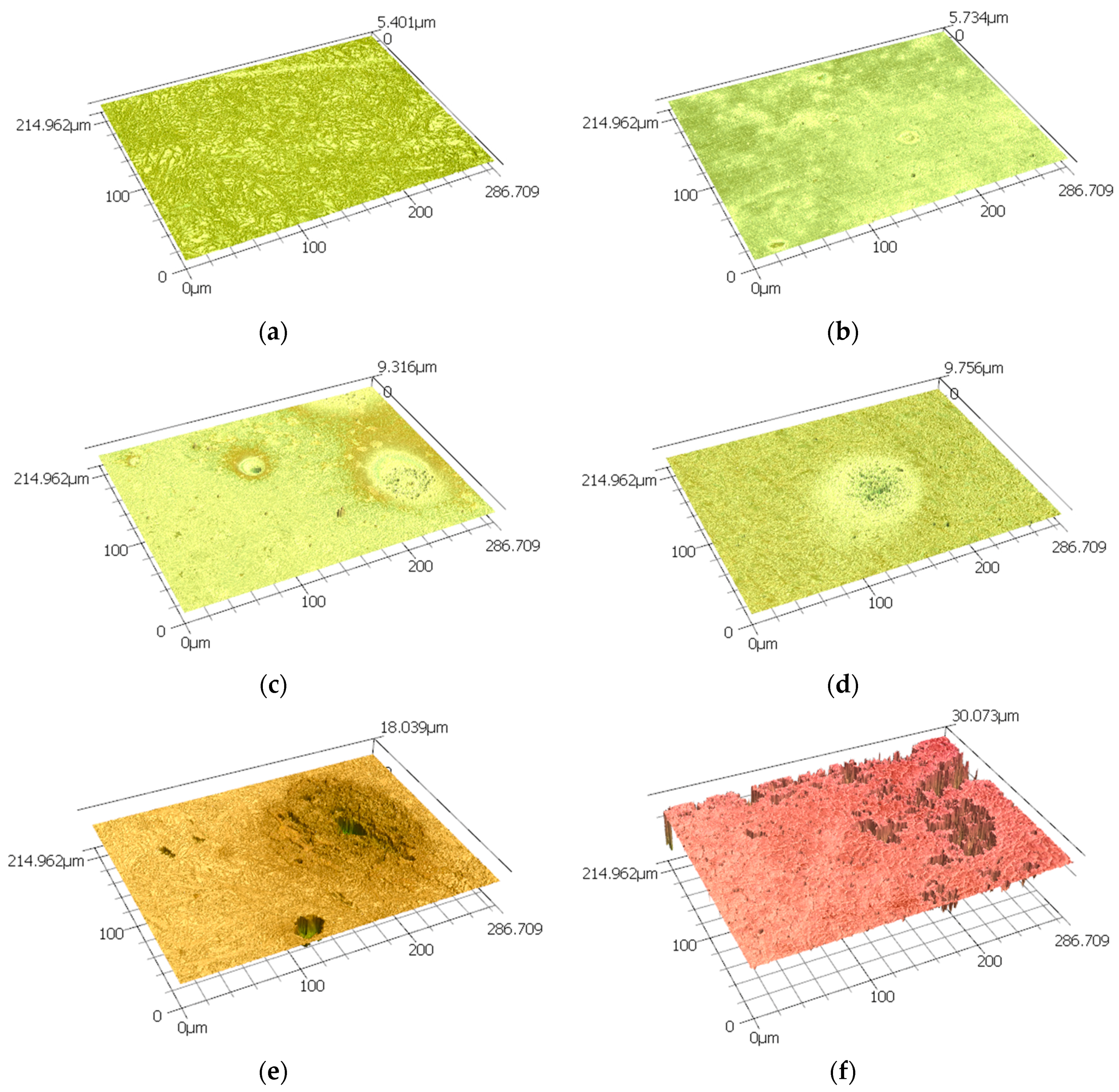

Figure 4.
The graph of weight loss in percentage as a function of time in hours.
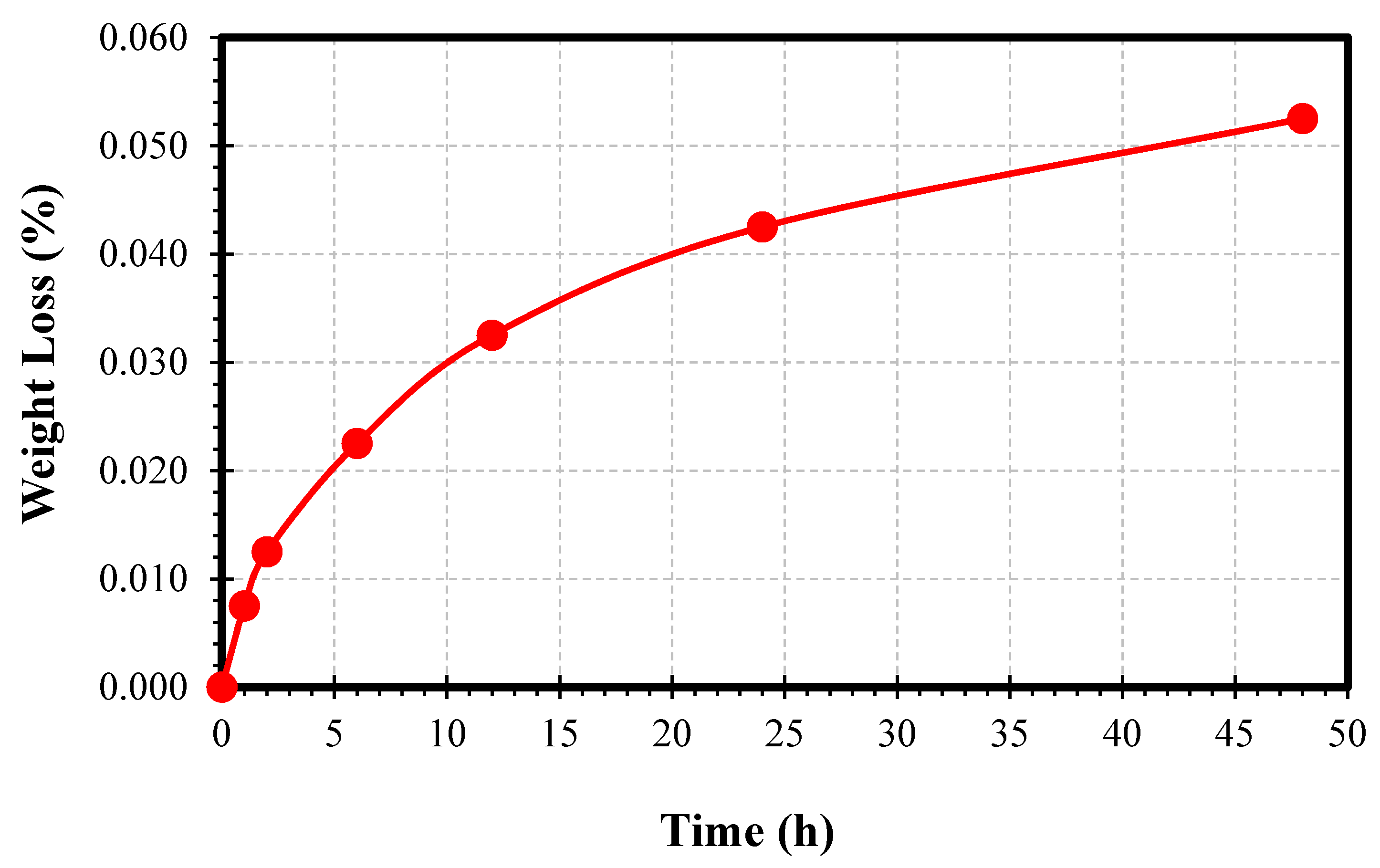
Figure 5.
Three-dimensional AFM topographic imaging of the steel surface after (a) 0 h, (b) 1 h, (c) 2 h, (d) 6 h, (e) 12 h, (f) 24 h and (g) 48 h of exposure to 0.5 M NaCl media.
Figure 5.
Three-dimensional AFM topographic imaging of the steel surface after (a) 0 h, (b) 1 h, (c) 2 h, (d) 6 h, (e) 12 h, (f) 24 h and (g) 48 h of exposure to 0.5 M NaCl media.
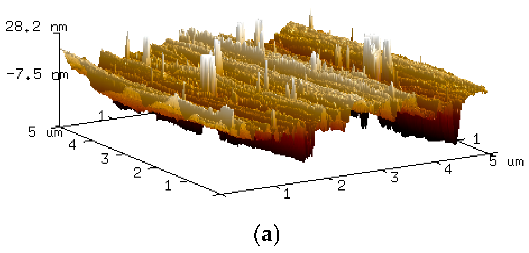
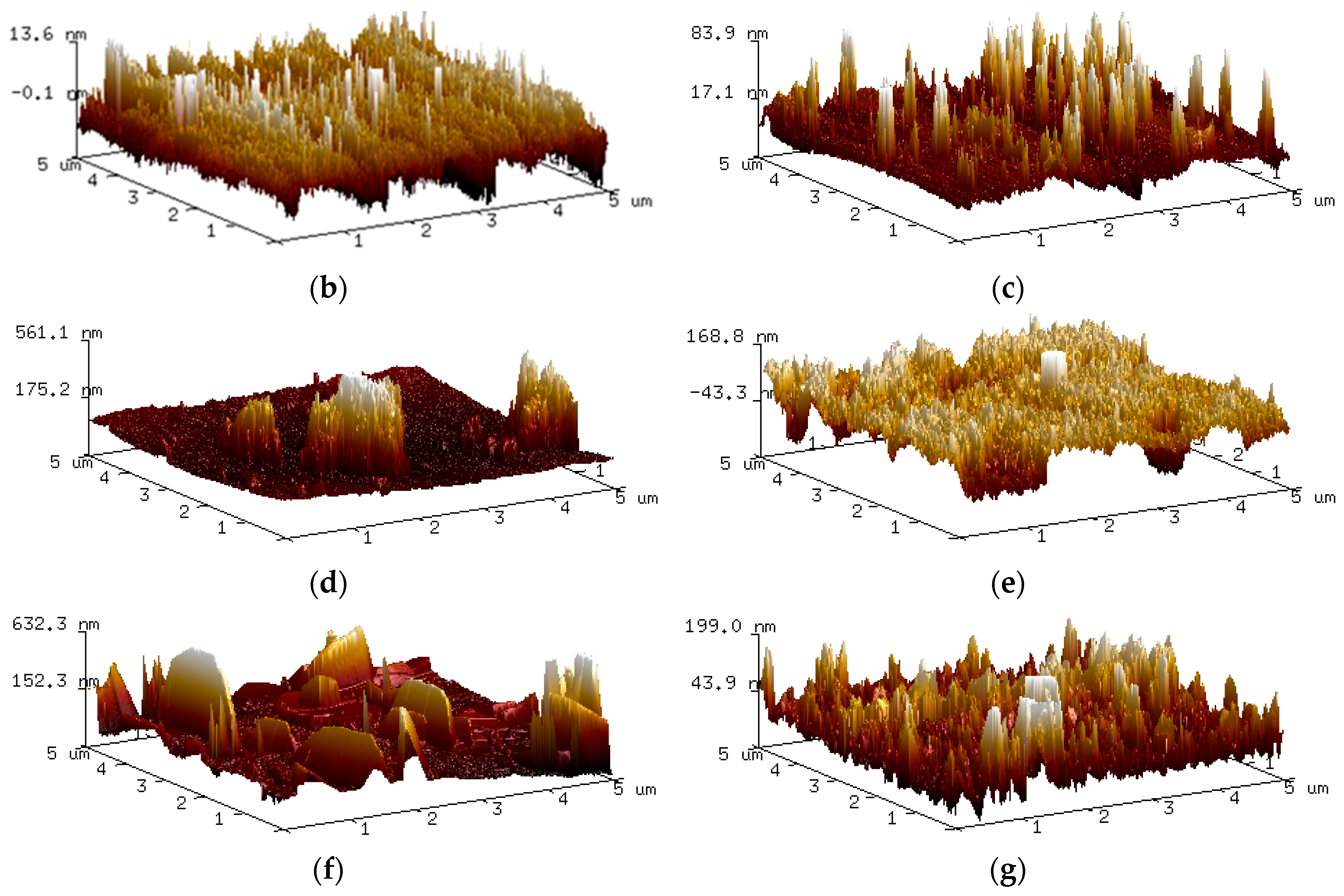
Figure 6.
Various line scan profiles were obtained from the AFM’s measurement area. The separation distance between each line was applied to avoid overlaying.
Figure 6.
Various line scan profiles were obtained from the AFM’s measurement area. The separation distance between each line was applied to avoid overlaying.


Table 1.
Averages of surface roughness for Ra, Rz.
| Time (h) | Ra (µm) | Rz (µm) |
|---|---|---|
| 0 | 0.072 | 5.401 |
| 1 | 0.028 | 5.734 |
| 2 | 0.065 | 9.106 |
| 6 | 0.153 | 9.756 |
| 12 | 0.496 | 17.754 |
| 24 | 1.646 | 28.295 |
| 48 | 3.996 | 30.339 |
© 2017 by the authors. Licensee MDPI, Basel, Switzerland. This article is an open access article distributed under the terms and conditions of the Creative Commons Attribution (CC BY) license (http://creativecommons.org/licenses/by/4.0/).
Share and Cite
MDPI and ACS Style
Handoko, W.; Pahlevani, F.; Sahajwalla, V. Corrosion Behaviour of Dual-Phase High Carbon Steel—Microstructure Influence. J. Manuf. Mater. Process. 2017, 1, 21. https://doi.org/10.3390/jmmp1020021
AMA Style
Handoko W, Pahlevani F, Sahajwalla V. Corrosion Behaviour of Dual-Phase High Carbon Steel—Microstructure Influence. Journal of Manufacturing and Materials Processing. 2017; 1(2):21. https://doi.org/10.3390/jmmp1020021
Chicago/Turabian StyleHandoko, Wilson, Farshid Pahlevani, and Veena Sahajwalla. 2017. "Corrosion Behaviour of Dual-Phase High Carbon Steel—Microstructure Influence" Journal of Manufacturing and Materials Processing 1, no. 2: 21. https://doi.org/10.3390/jmmp1020021