A Computer-Aided Sustainable Modelling and Optimization Analysis of CNC Milling and Turning Processes

School of Science, Engineering and Information Technology, Federation University, Mt Helen Campus, Ballarat 3350, Australia
*
Author to whom correspondence should be addressed.
J. Manuf. Mater. Process. 2018, 2(4), 65; https://doi.org/10.3390/jmmp2040065
Submission received: 20 August 2018
/
Revised: 7 September 2018
/
Accepted: 25 September 2018
/
Published: 27 September 2018
(This article belongs to the Special Issue Towards Sustainable Manufacturing Processes)
Abstract
:The sustainability of a manufacturing process can be measured by three main factors which impact both ecological and financial constraints. These factors are the energy required to achieve a specific job, the material utilized for the job, and the time taken to complete that job. These factors have to be quantified and analysed so that a proper manufacturing system can be designed to optimize process sustainability. For this purpose, a computer package, which utilizes life cycle inventory models has been presented for CNC (Computer Numerical Control) milling and turning processes. Based on utilization of resources and production stages, the job completion time for the turning and milling processes can be divided into process (i.e., machining), idle and basic times. As parameters are different for evaluating the process times, i.e., depth and width of cut in case of milling, initial and final diameters for turning, two different case studies are presented, one for each process. The effect of material selection on the sustainability factors has been studied for different processes. Our simulations show that highly dense and hard materials take more time in finishing the job due to low cutting speed and feed rates as compared to soft materials. In addition, face milling takes longer and consumes more power as compared to peripheral milling due to more retraction time caused by over travel distance and lower vertical transverse speeds than the horizontal transverse speed used in a peripheral retraction process.
1. Introduction
The system design for sustainable manufacturing is achieved by considering both ecological and financial constraints. Business concerns are growing with sustainable business models and environmental accounting as today there is no agreed-upon single standard. So, there are large number of techniques to measure the whole environmental footprint belonging to an association or supplying sequence. Nowadays, the utmost imperative encountered by civilization and industry is the climate and environmental impacts due to rapid usage of energy. When fuel is combusted or electricity is being used on-site in some way, the most significant greenhouse gas that is emitted is carbon dioxide (CO2). At the time of manufacturing, the basic factor that needs to be tackled is the growing energy budget. So, to make massive savings throughout the equipment lifespan, more energy efficient solutions are essential. Business benefits and the ecological execution can be improved by applying sustainability standards to machining forms [1]. Sustainability indicators are mainly classified into three main types: environmental, economic and social as shown in Figure 1.
For many organizations, new zones of achievement are imposed by varying demands and requests from customers, administrative guidelines and shifting competition. Today not just quality, time, adaptability and cost necessities are encountered, but also continuous expanding pressure on natural resources. To accomplish sustainable production, conventional financial focus requests and environmental impact must be satisfied. In the production method, a variety of indicators are utilized with regard to time, cost and quality at various stages to raise economic output. It is very necessary to outline standards, signs and approaches to allow more ecologically kind production, as work centered on CNC machining. Fundamentally ecological enhancements of CNC machining can be accomplished through innovation improvements or using more powerful strategies. In general, these should consider the CNC machining sustainable production to incorporate the given features, which are impacted by decisions prepared at the time of process planning [2].
- Cost (labor, machine apparatuses, cutting instruments—as a capacity of machining time).
- Environment (energy used, material and process emission from use of cutting solutions).
- Quality (process capacity, scrap rate, in process control needs and so forth).
- Lead time (material evacuation rates, diminished set-up times—consequently diminished standby circumstances).
- Flexibility (routines, knowledge base engineering and competence) it is vital to comprehend the interrelation between various machining factors, choices, imperatives and so forth and their separate effect on the machining result.
Manufacturing industry is an imperative mainstay of the world’s economy. It is basic to have a solid base of manufacture as it empowers the various divisions of any industrialized nation [3]. The matter of sustainability has been broadly perceived as a need in manufacturing research. Numerous new terminologies, for example, ecologically aware manufacturing, energy effective manufacturing, remanufacturing, and product lifespan engineering, have been recommended. An energy consumption model is essential for pretending energy consumption in an expansive number of various situations rapidly. CNC machine devices are the key players in the present-day machining industry. Its principal natural effect is recognized in energy consumption during the utilization stage, which represents over 95% of the life cycle energy use. CNC machines are involved in various motors and helper segments whose energy utilization can fluctuate emphatically during production [4]. The pattern towards a higher level of automation of CNC will, as needs be, develop the energy aspect of the aggregate cost. An unambiguous data format is desirable to simplify energy data exchange among dissimilar happenings of a production system. This is especially valid in a situation where distinctive events, e.g., designing, plan, fabrication and data storage, are distributed geographically. Thus, to characterize and incorporate energy data, a standardized data model is considered as a viable solution. The energy features of CNC machining have a tendency to be extremely composite, fluctuating meaningfully with respect to method design and the variety of operative procedures. An examination of current writing concentrates on energy requests displayed for CNC machining [5]. The primary energy necessity of a machining procedure is steady energy utilization and variable utilization. The static energy is required by the supplementary devices of machines to confirm its operative readiness, although the inconstant energy consumption is reliant on its processing rate. A comparable report was compiled by [6] where the particular energy utilization of a machining procedure is assessed in light of a consistent and a variable segment with identified material removal rate. These mathematical models provided an invaluable basis for in-depth energy analysis of CNC machining.
Most studies have been based on machining parameters to analyze energy consumption for CNC machining systems. Gutowski et al. [7] provided specific electricity consumption dependent needs for manufacturing CNC operations. They found that these needs vary from process to process and depend upon the rate of machining processes and energy-use operations are increasing day by day. Diaz et al. [8] studied the procedures for exemplifying and minimizing the consumption of electrical energy of CNC milling tools. They measured the power demands and specific energy variables of a micro-machining tools in which they use low carbon steel for cutting under different material removing rates. A similar procedure has been adopted for cutting aluminum as well as poly-carbonate materials in order to make comparisons and find the differences for specific energy for individual materials with respect to steel. Rajemi et al. [9] assessed ideal instrument life for least energy of a turning procedure by considering the energy spending plan in manufacturing an item. The study concludes the increase in tool life and hence decreases in energy usage in order to gain more value out of high-energy tools. Mori et al. [10] researched the significant causes of a decrease consumption of power in tooling process of the machine and three cases are considered with the following findings: (1) utilization of power can be decreased for basic types of milling operations; (2) utilization of power for machining deep holes can be lessened with a versatile pecking cycle; (3) utilization of power can be lessened further by synchronizing the spindle accelerating/de-accelerating speed with the feed axis at rapid traversing operation. Avram and Xirouchakis [11] proposed a method estimating variable energy requires of a machining tool system in part machining. They used cutter location and speed data. During the material removal processes, energy savings need to be considered in order to fix the match between the efficiency requirements of a machine to that of the proficiencies of the machine, hence magnitude and duration of machine running are taken into account. Hu et al. [12] propose on-line energy monitoring for developing the efficiency of energy of tools used in a CNC machining process. They propose reduction in initial energy consumption using task scheduling in which, ready-for-operation time and idling time can be reduced and then provide some technology-related measurements so that cutting parameters can be optimized so that cutting time for the processes can be reduced. Calvanese et al. [13] proposed an energy consumption model for the machine tooling used in the milling CNC machining processes. They provide optimization of the cutting variables and conditions in order to minimize the energy consumption in the milling process. Different machine tool functional modules and production phases were considered. Draganescu et al. [14] studied out the importance of a mathematical model of tool efficiency of the machine to determine the electrical energy consumed during the machining operation. They find out the possibilities of the statistic modeling efficiency of machine tools with the functions as working parameters by taking data from response surface methodology experiments. Kara et al. [15] presented an empirical approach for unit-process energy calculations used for material removal operations. The proposed unit-process energy consumption model finds that that a higher MRR (Material Removal Rate) results less energy consumed in removing same amount of material volume as compared to lower MRR rates. Guo et al. [16] proposed two step methods in calculating the ideal cutting factors for finishing–turning processes in order to minimize the total energy consumption by achieving a quantified surface roughness. For this, they derived an energy and surface roughness model for a particular defined machine tool taken in the study.
To accomplish sustainable manufacturing, it is important to evaluate the sustainability performance regarding how well products are produced in a sustainable manner. There have been many frameworks for sustainability assessment and indicators, which evaluate the sustainability performance of manufacturing industries. These indicators are categorized into social, economic and environmental indicators based on available data and commonly measured aspects of production like materials use, energy use, water consumption, products, waste, air emissions etc. A manufacturing process generally consists of a number of unit processes. There are a number of issues, which increase the level of complexity in the manufacturing processes. These issues are different types of energy resources, energy usage at various stages with variation in employed power, number of materials, wastage of material at different levels, labor cost, product manufacturing cost, and cost of tooling and equipment. Manufacturing industries are focusing on the sustainability analysis of manufacturing processes. The present methods are used for determination of sustainability analysis for a product having following designs:
- complex mathematical relations are involved;
- manual calculations need to be used that are prone to error;
- a lot of literature needs to be referred to for collecting the data;
- lot of human effort is required at every stage;
- this is an iterative and time-consuming process [17].
Hence, there is a need for computer-aided system that automatically assesses sustainability of different process plans at the early design stage and benefitting the industry. The system would help in minimizing the use of non-renewable sources, choosing energy efficient processes, minimizing waste, reduce product manufacturing cost, labor cost and reduce carbon emissions. To advance sustainability assessment analysis, machining processes need reliable measurement methods to evaluate performance of the machining processes by considering the factors of production volume, elapsing time of the process energy consumption, power consumption wastage etc.
- To determine performance metrics for a milling and turning process.
- To propose a methodology for determining science-based measurements for both machining processes.
- To develop a computer model that could evaluate sustainability of machining processes from process plan of the part with the help of MATLAB Software.
- To verify the proposed methodology, compare output data obtained from the machining processes (face milling, peripheral milling and turning).
2. Methodology for Sustainable Modeling for Milling/Turning Process
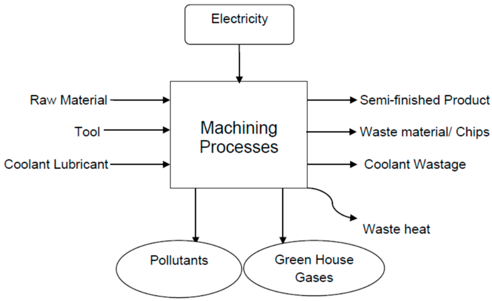
To evaluate a machining procedure productively with reusable methods in terms of ecological effects, the idea of a unit task is employed. The unit-process comprises of the data sources or inputs, process, and yields of a task, i.e., outputs. The unit-process outline of a milling/turning procedure is demonstrated in Figure 2. Production of final product from the input raw material is characterized by the following attributes:
- input sources or materials;
- energy requirements;
- material loss (whether recycle or waste);
- the main machine (or material) factors which relate the inputs shown in Figure 2 to the outputs.
2.1. Sustainability Analysis for the Machining Process
Energy and the loss of material are employed in the present paper as the main characteristics on which the sustainability analysis is based. As such, the following sections are presented by way of example to highlight how these two characteristics are quantified in the machining process.
Total energy, , consists of the sum of the idle, the basic and the machining energies. The equation used for calculating total energy is given as follows,
where,
- = Basic power;
- = Basic time;
- = Ideal power;
- = Ideal time;
- = Machining power;
- = Machining time.
It is worth noting here that the above parameters which determine the energy consumption for a specific machining process depend on such aspects as the workpiece material, the type of process, and the machine used to effect the cutting.
The material lost by the workpiece during the machining process is commonly known as the chip mass. This can be calculated from the material’s density, , workpiece length, , and both the depth and width of cut as follows,
where,
- = Width of cut;
- = Depth of cut;
- = Volume of material;
- = Mass of chip.
It is worth noting here that, in case of turning, the volume of the removed metal is calculated as follows:
where,
- = Initial workpiece diameter;
- = Final workpiece diameter.
2.2. Developing Graphical User Interface in MATLAB
The fundamental machining equations shown above have been implemented as part of the MATLAB package which encompasses a large database of material, machine specifications and machining process. The MATLAB package has been built to help manufacturing engineers make decisions in relation to which combination or material, process and machine is likely to produce the optimal outcome with respect to energy consumption and material losses. The mathematical models, upon which the MATLAB package is built, take the input variables, type of material used for workpiece and type of CNC machining operation selected for a particular case study. Other parameters included in the intricate programming procedure used in the MATLAB package are as follows:
- specific cutting energy (W/mm3 per sec),
- cutting speed (m/min),
- feed per teeth (mm/rev),
- density (kg/m3) and
- X-Y transverse speeds while retracting step for different types of workpiece materials.
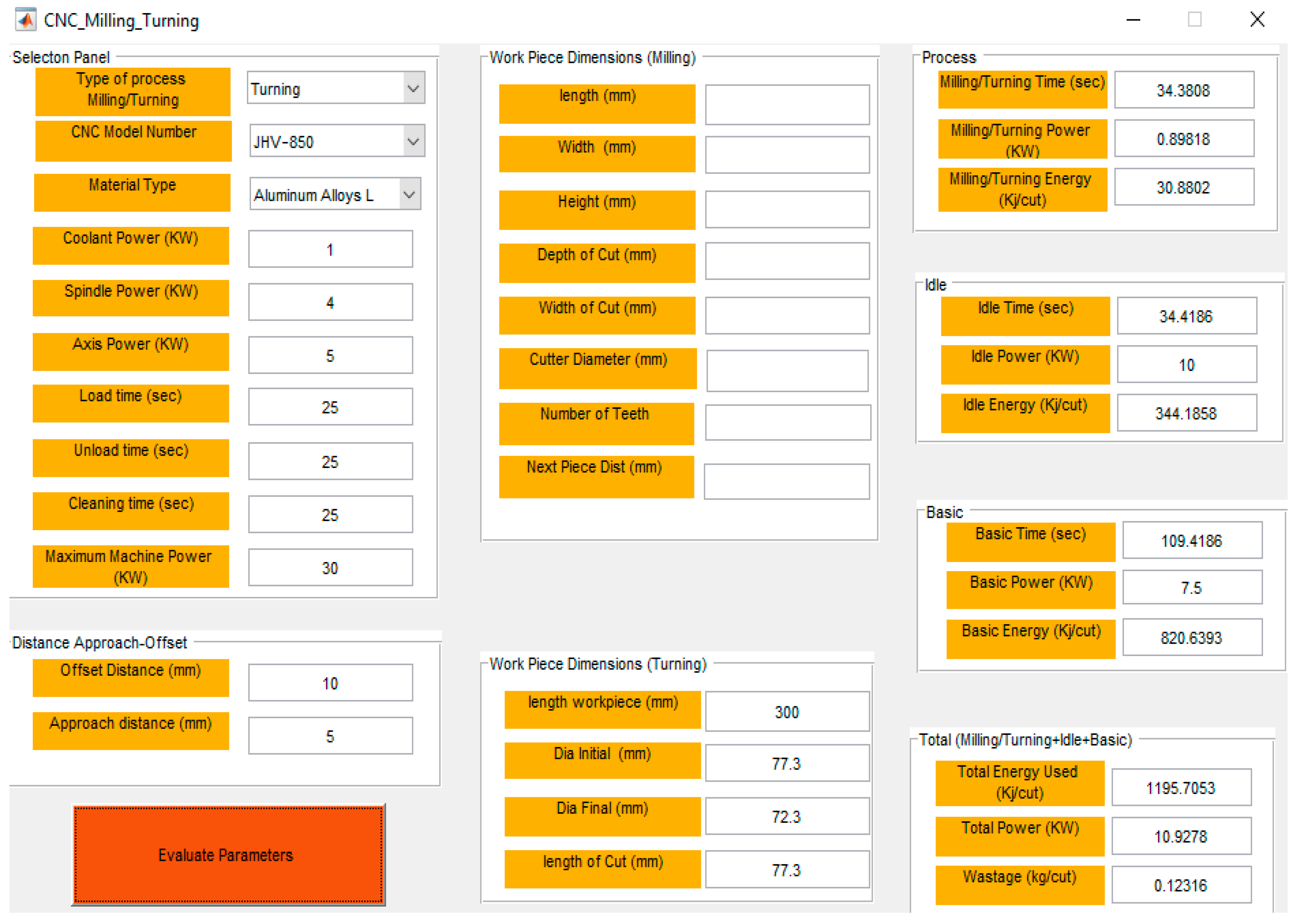
Two case studies have been considered here in which dimensions and parameters for initial and desired final product have been assumed. The first case study features a milling process which takes into account both face and peripheral milling. The second case study attempts to employ turning to achieve the desired machining outcome. Details of the case studies along with GUI (Graphic User Interface) screenshots for input and output attributes are given in Figure 3.
2.2.1. Case Study 1, the Milling Process
A parallelepiped aluminum-alloy workpiece, of dimensions 600 mm × 150 mm × 70 mm and mass 17 kg, is considered for this case study. The aim is to analyse the consumption of energy by milling a cut of a diameter 160 mm and depth 4 mm.
As shown in Figure 3, a number of parameters need to be put through the GUI and some parameters are read directly from a previously stored database. The output of the calculations is given in terms of time, power, energy and material wastage in different sections of the processes. For this case study, end milling was initially considered and then the process is repeated for peripheral milling in which there is a difference of one parameter; this is the extension of cutting tool that goes away from the workpiece. The results for this operation is shown in Figure 4.
2.2.2. Case Study 2, the Turning Process
A cylindrical-shaped aluminum alloy workpiece has been considered for this case study. The initial diameter of the workpiece is 77.3 mm and its final diameter is required to be 72.3 mm with a bar length of 300 mm. The aim is to analyze the consumption of energy by turning the whole bar length. The workpiece has a mass of 3.8 kg.
As the turning process is different from milling, specific cutting energy, cutting speed, feed rates differ in this process. As the material is reduced progressively from the outer diameter, different parameters and type of job have been assumed for the turning process.
As the length of the workpiece, initial and final diameters and length of cut are different here to the milling process pointed out in case study 1, a separation has been provided for dissimilar parameters for both turning and milling processes. The output results for the turning case study has been shown in Figure 5.
3. Analysis for Sustainability Optimization
In the current paper, the sustainability of the machining process is regarded as a function of three basic parameters: the energy consumption, the process time and the material wastage. As such, the process whose combined outcome is likely to produce the minimized values of these parameters is taken as the optimal manufacturing choice.
3.1. Comparison of Face and Peripheral Milling Operations for Different Output Parameters
The section shows the results obtained by simulating different types of CNC milling processes and by considering different types of workpiece material. A comparison is graphically provided here for face and peripheral milling of the same material in terms of time, energy, power and wastage.
Figure 6 compares face milling to end milling in relation to various times involved in the manufacturing process. In the face milling process as the cutter needs to travel across the workpiece it has extra over travel time than the peripheral process which results in taking more milling idle and basic times. As 12 s was over travel time for the cutting tool, process time for the face milling was 68.1 s and 56.1 s for the peripheral milling. Similarly, other times, i.e., idle basic times, have similar differences as they have added process time included in them.
Power consumption was similar for process idle and basic per unit times, but total power consumption is more in face milling as the total power consumed depends upon total energy and total time taken by the process. Total power consumption per cut for face milling and peripheral processes is 15.1 and 14.5 kW, respectively, as Figure 7 clearly shows.
As shown in Figure 8, energy consumption depends upon elapsing time of the process, face milling consumes more power than the peripheral process. Total energy consumption for face and peripheral processes is 1814 and 1546 kJ/cut, respectively.
3.2. Effect of Material Selection on the Sustainability Parameters in the Milling Process
Six different materials have been selected in order to compare sustainability parameters (time, energy and material waste) in both the face and peripheral milling processes. All materials are taken with their possible lower cutting speeds and feed rates. The comparison has been shown for different output parameters for both face and peripheral operations.
Figure 9 shows total power consumption for different types of workpiece materials. As feed rates and cutting speeds are lower for less dense materials (aluminum and magnesium), they consume more time and hence more power per cut as compared to hard and highly dense materials like titanium, stainless steel, hard steel and cast iron. Our analysis suggests the cutting power is about 15 kW for aluminum and magnesium materials whereas it is approx. 17 kW for highly dense materials.
As hard steel requires low cutting speed (15 m/min) and feed rate (0.005 mm per tooth), which are far less than the values used for other materials, it consumes more time to complete the process and hence higher energy consumption is observed. Steel consumes approx. 546 MJ of energy per milling operation for face milling process, which is about five fold the energy required by other materials. The comparison of different material with face and peripheral milling process is shown in Figure 10.
3.3. Effect of Material Selection on the Sustainability Parameters in the Turning Process
Feed rate and cutting speeds for turning operation are different from that of the milling operations and are slightly higher for most of the materials. Power consumption depends upon the time consumed by a given process, which in turn depends upon specific cutting energy, cutting speed and feed rate of the material, and hence varies from material to material. As Figure 11 suggests, titanium, stainless steel and hard steel consume more power than the aluminum and magnesium materials, which is about 10–10.5 kW for these materials. For other materials it is about 8 kW per cut.
Similarly, as Figure 12 shows, the energy consumed to machine titanium, stainless steel and hard steel (831–882 kJ) is more than the aluminum and magnesium materials (appx. 600 kJ).
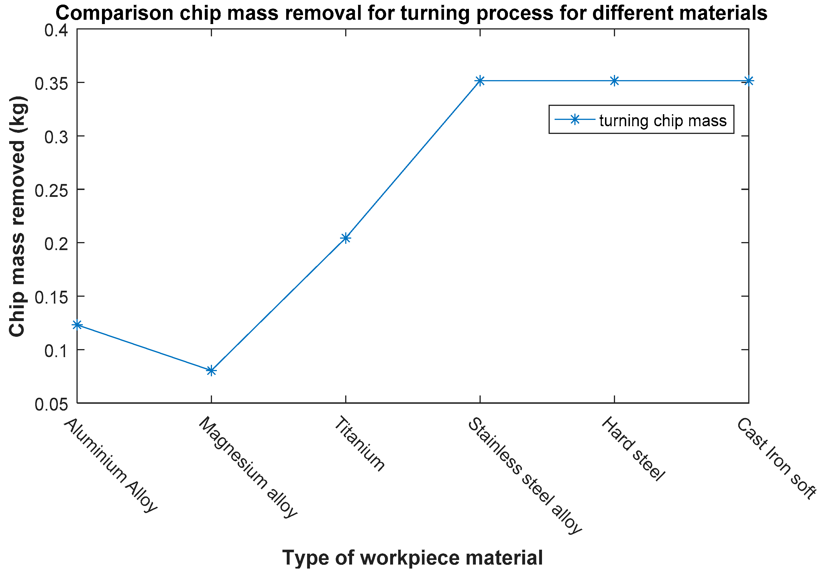
As density of the materials varies, chip mass removed also varies with it. Stainless steel, hard steel and cast iron has similar and high density then the rest; chip mass removed is larger for these materials (approx. 0.35 kg). Chip mass removed for aluminum and magnesium workpieces is about 0.12 and 0.08 kg, respectively, as clearly shown in Figure 13.
4. Conclusions
The input of the presented work is a number of parameters, i.e., cutter-diameter, cutting-speed, feed rate, number of teeth (if milling process), depth and width-of-cut (if milling), initial-final diameters and length of cut (if turning), rapid transverse speeds, some properties of material of workpiece (specific cutting energy, feed rate etc.), coolant, axis and spindle powers, load–unload-clean times, offset-approach distance etc. and output is times, power, energy at different phases of the machine process, along with chip mass which is the wastage material removed after finishing the job part. Two different case studies have been presented each for a milling process and a turning process. A further two types of milling processes have been considered named as face and peripheral milling. Evaluation of results has been done by showing outputs in graphical form by taking aluminum alloy as the material of choice in both case studies. It is concluded that face milling takes more time in finishing the same process than peripheral milling and consumes more power and energy. For an aluminum alloy workpiece, total time taken by the face milling operation is 106.5 s as compared to 119.7 s by peripheral milling. The case study has been extended by considering six different materials of workpieces in which aluminum alloy, magnesium alloy, titanium, stainless steel alloy, hard steel and soft cast iron have been used. It has been concluded that hard materials takes more time and consumes more power and energy than soft materials. For example, in the turning process moderate power consumption has been found for aluminum and magnesium alloys which are 14.5 and 13.5 kW, respectively. Power consumption is high for titanium (17.5 kW), stainless steel alloy (17.2 kW), hard steel (17.4 kW) and soft cast iron (16.7 kW) workpieces. As hard steel needs to be cut with very lower cutter speeds and feed rate, it consumes far more energy as compared to other materials. Aluminum and magnesium alloys show lower energy consumption figures of 1545.9 kJ/mill and 1393.0 kJ/mill, respectively. Similar results have been shown for the milling process as well.
In the present work only electrical energy consumption, cutter fluid, lubricants, cutter tool, wastage/chip mass have been taken into account for sustainability, and hydraulic, air compression–decompression, labour cost or other costs are not considered, so more factors need to be taken into account in order to reach the real attributes involved in the process. For materials taken in the study, only lower and higher ranges of cutting speeds and feed rates have been considered, and the effects on tool wear and type of finished surface are not considered in the evaluations for the speeds employed. Work can be extended to optimize the cutting speeds and feeds for a particular material so that maximum output can be produced with minimum tool wear or other losses of the machine and with minimum energy consumption.
Author Contributions
K.S. undertook experiments, analysis and contributed to the writing of this work. I.A.S. supervised this investigation and contributed to the writing of this work.
Funding
This research received no external funding.
Acknowledgments
The authors sincerely extend their appreciation to Federation University Australia for providing an opportunity for this research project.
Conflicts of Interest
The authors declare no conflict of interest.
References
- Deaib, I. On Energy Efficient and Sustainable Machining through Hybrid Processes. Mater. Manuf. Process. 2014, 29, 1338–1345. [Google Scholar] [CrossRef]
- Anderberg, S.; Beno, T.; Pejryd, L. Energy and cost efficiency in CNC machining from a process planning perspective. In Sustainable Manufacturing; Springer: Berlin/Heidelberg, Germany, 2012; pp. 393–398. [Google Scholar]
- Lee, J.Y.; Kang, H.S.; Noh, S.D. MAS2: An integrated modeling and simulation-based life cycle evaluation approach for sustainable manufacturing. J. Clean. Prod. 2014, 66, 146–163. [Google Scholar] [CrossRef]
- Bhanot, N.; Rao, P.V.; Deshmukh, S.G. An integrated sustainability assessment framework: A case of turning process. Clean Technol. Environ. Policy 2016, 18, 1475–1513. [Google Scholar] [CrossRef]
- Li, Y.-F.; Wang, Y.-L.; He, Y.; Wang, Y.; Lin, S.-L. Modeling Method for Flexible Energy Behaviors in CNC Machining Systems. Chin. J. Mech. Eng. 2018, 31, 1–11. [Google Scholar] [CrossRef]
- Peng, T. An interoperable energy consumption analysis system for CNC machining. J. Clean. Prod. 2017, 140, 1828–1841. [Google Scholar] [CrossRef]
- Gutowski, T.; Dahmus, J.; Thiriez, A. Electrical energy requirements for manufacturing processes. In Proceedings of the 13th CIRP International Conference on Life Cycle Engineering, Leuven, Belgium, 31 May–2 June 2006; pp. 1–6. [Google Scholar]
- DIaz, N.; Redelsheimer, E.; Dornfeld, D. Energy Consumption Characterization and Reduction Strategies for Milling Machine Tool Use. In Proceedings of the CIRP International Conference on Life Cycle Engineering, Braunschweig, Germany, 2–4 May 2011; Springer: Berlin/Heidelberg, Germany, 2011; pp. 263–267. [Google Scholar] [Green Version]
- Rajemi, M.; Mativenga, P.; Aramcharoen, A. Sustainable machining: Selection of optimum turning conditions based on minimum energy considerations. J. Clean. Prod. 2010, 18, 1059–1065. [Google Scholar] [CrossRef]
- Mori, M.; Fujishima, M.; Inamasu, Y.; Oda, Y. A study on energy efficiency improvement for machine tools. CIRP Ann. 2011, 60, 145–148. [Google Scholar] [CrossRef]
- Avram, O.; Xirouchakis, P. Evaluating the use phase energy requirements of a machine tool system. J. Clean. Prod. 2011, 19, 699–711. [Google Scholar] [CrossRef]
- Hu, S.; Liu, F.; He, Y.; Hu, T. An on-line approach for energy efficiency monitoring of machine tools. J. Clean. Prod. 2012, 27, 133–140. [Google Scholar] [CrossRef]
- Calvanese, M.L.; Albertelli, P.; Matta, A.; Taisch, M. Analysis of Energy Consumption in CNC Machining Centers and Determination of Optimal Cutting Conditions. In Proceedings of the CIRP International Conference on Life Cycle Engineering, Singapore, 17–19 April 2013; Springer: Singapore, 2013; pp. 227–232. [Google Scholar]
- Draganescu, F.; Gheorghe, M.; Doicin, C. Models of machine tool efficiency and specific consumed energy. J. Mater. Process. Technol. 2003, 141, 9–15. [Google Scholar] [CrossRef]
- Kara, S.; Qureshi, F.; Li, W.; Herrmann, C. Unit process energy consumption models for material removal processes. CIRP Ann. 2011, 60, 37–40. [Google Scholar] [CrossRef]
- Guo, Y.; Loenders, J.; Duflou, J.; Lauwers, B. Optimization of Energy Consumption and Surface Quality in Finish Turning. Procedia CIRP 2012, 1, 512–517. [Google Scholar] [CrossRef]
- Singh, K.; Sultan, I. Framework for Sustainability Performance Assessment for Manufacturing Processes—A Review. In IOP Conference Series: Earth and Environmental Science; IOP Publishing: Bristol, UK, 2017; Volume 73, pp. 1–6. [Google Scholar]
Figure 1.
Sustainability as the intersection of its three key parts.

Figure 2.
Initial workpiece and finished product diagram of a milling/turning process.

Figure 3.
A GUI showed both inputs (column first and second) and outputs (column 3) for a face milling process.
Figure 3.
A GUI showed both inputs (column first and second) and outputs (column 3) for a face milling process.

Figure 4.
A GUI showed both inputs (column first and second) and outputs (column 3) for a peripheral milling process.
Figure 4.
A GUI showed both inputs (column first and second) and outputs (column 3) for a peripheral milling process.

Figure 5.
A GUI showed both inputs (column first and second) and outputs (column 3) for the turning process.
Figure 5.
A GUI showed both inputs (column first and second) and outputs (column 3) for the turning process.

Figure 6.
Comparison of milling, idle and basic times for face and peripheral process.

Figure 7.
Comparison of milling, idle, basic and total power for face and peripheral process.

Figure 8.
Comparison of milling, idle, basic and total energy consumption for face and peripheral process.
Figure 8.
Comparison of milling, idle, basic and total energy consumption for face and peripheral process.

Figure 9.
Comparison of total power consumed for face and peripheral processes for different materials.
Figure 9.
Comparison of total power consumed for face and peripheral processes for different materials.

Figure 10.
Comparison of total energy consumed for face and peripheral processes for different materials.
Figure 10.
Comparison of total energy consumed for face and peripheral processes for different materials.

Figure 11.
Comparison of total power consumed for turning processes for different material.

Figure 12.
Comparison of total energy consumed for turning processes for different materials.

Figure 13.
Comparison of chip mass removal for turning processes for different materials.

© 2018 by the authors. Licensee MDPI, Basel, Switzerland. This article is an open access article distributed under the terms and conditions of the Creative Commons Attribution (CC BY) license (http://creativecommons.org/licenses/by/4.0/).
Share and Cite
MDPI and ACS Style
Singh, K.; Sultan, I.A. A Computer-Aided Sustainable Modelling and Optimization Analysis of CNC Milling and Turning Processes. J. Manuf. Mater. Process. 2018, 2, 65. https://doi.org/10.3390/jmmp2040065
AMA Style
Singh K, Sultan IA. A Computer-Aided Sustainable Modelling and Optimization Analysis of CNC Milling and Turning Processes. Journal of Manufacturing and Materials Processing. 2018; 2(4):65. https://doi.org/10.3390/jmmp2040065
Chicago/Turabian StyleSingh, Karmjit, and Ibrahim A. Sultan. 2018. "A Computer-Aided Sustainable Modelling and Optimization Analysis of CNC Milling and Turning Processes" Journal of Manufacturing and Materials Processing 2, no. 4: 65. https://doi.org/10.3390/jmmp2040065