Sheet Metal Profiles with Variable Height: Numerical Analyses on Flexible Roller Beading

Institute for Production Engineering and Forming Machines, 64287 Darmstadt, Germany
*
Author to whom correspondence should be addressed.
J. Manuf. Mater. Process. 2019, 3(1), 19; https://doi.org/10.3390/jmmp3010019
Submission received: 18 December 2018
/
Revised: 10 January 2019
/
Accepted: 21 January 2019
/
Published: 1 February 2019
(This article belongs to the Special Issue Analysis and Modeling of Sheet Metal Forming Processes)
Abstract
:In the spirit of flexible manufacturing, the novel forming process “flexible roller beading” was developed, which allows the incremental production of height-variable sheet metal profiles. After designing the process and realizing a test facility for flexible roller beading, the feasibility was experimentally shown. The following step addresses the expansion of the process limits. With this aim, the mechanical behavior of the sheet metal during the process was investigated by means of FEA. Due to the variable cross-section development of the sheet metal profile, a multidimensional stress distribution was identified. Based on the present state of stress and strain, conclusions about the origin of appearing defect formations were drawn. Observed defects were sheet wrinkles as a result of compressive stresses in the profile flange and material thinning in the profile legs and bottom due to unintendedly exceeding tensile stresses. The influences of the forming strategy as well as tool- and workpiece-side variations on the quality of the manufacturing result were investigated. From the results of the analyses, measures to avoid component failure were derived. Given all the findings, guidelines were concluded that are to be considered in designing the forming sequence. With the insights into the occurring processes and the mastery of this novel forming process, important contributions are made to its industrial suitability. The approach of lightweight and load-oriented component design can be extended by realizing new families of sheet metal profiles. With respect to Industry 4.0, on-demand manufacturing is increasingly required, which is why flexible roller beading is of substantial relevance for the industrial sheet metal production.
1. Introduction
As a consequence of the so-called fourth industrial revolution or Industry 4.0 [1], the trend is moving away from conventional mass production [2]. The industrial change is moving towards mass customization, which implies increasing component variation and changeovers. Consequently, the requirements for the manufacturing systems are higher flexibility and on-demand manufacturing [2]. This change is accompanied by new manufacturing challenges and the further development of production technologies. The realization of several families of parts on the same system with shortened changeover time constitutes one objective of flexible manufacturing systems [3]. Another purpose of flexible processes is the economization of material expenditure by producing load-oriented components [4]. According to Yang et al. [2], the flexibility level can be raised by “increasing the degree of freedom by using non-dedicated tools and by varying forming path”. In incremental profile forming, this means the implementation of flexible roll movements. The most widespread manufacturing process for cold-rolled profiles is roll forming as a pure bending process [5]. The product family of conventional roll forming is limited to sheet metal profiles with constant cross-sections along the longitudinal direction. Flexibility in roll forming can be achieved by using movable rolls which enable the production of width-variable transverse sections [6,7]. Lindgren et al. [8] presented a process extension by manufacturing profiles with conical width and depth development. The profile flanges were formed alternately and the gradient of the conically shaped height contour was constant. In the work of Sedlmaier et al. [9], an approach to produce height-variable profiles is presented. In this process, the sheet metal is clamped in a die with prefabricated shape, where the profile bottom already takes the final height-variability. Subsequently, roll forming tools gradually form the profile flanges by moving along flexible trajectories. In this approach, the profile height contour is predefined by the given die-shape and the profile length is limited as well.
The developed incremental forming process called “flexible roller beading” expands the potential of lightweight design by manufacturing sheet metal profiles with height-variable cross-sections [10]. The flexible manufacturing system enables the production of novel profile families by enabling the customization of the profile height contours. In this case, the shaping of the height contour of the profile is not given by the tool geometry but the forming tool paths. This allows short changeover times and the ability of on-demand production, which comply with the trend of the modern manufacturing industry. The resulting sheet metal components can be used as load-oriented carrier profiles as well as semi-finished products with height-variable beads [10]. The beads in the semi-finished sheet metals can be used as material buffers in downstream forming processes. Due to the height-variability of the beads, varying amounts of material can be provided at critical positions of the component. The aim of using these kinds of semi-finished products is to expand the limits of forming processes like hydroforming.
The manufacturing of profiles with inconstant cross-sectional developments involves the presence of a multidimensional state of stress during the process. In flexible roll forming, longitudinal strains are necessary to obtain the intended profile geometry in the transition zone, where the profile changes its cross-section [11]. The transition area is divided into a stretching zone, where the profile shape is concave and a compression zone with a convex contour. The control over the appearing compressive longitudinal stresses avoids component defects in the form of flange buckling [12]. Current research addresses the development of countermeasures to reduce the geometric deviations resulting from the multidimensional stress distribution [13]. To optimize the novel process of flexible roller beading, a fundamental understanding of the appearing stress and strain distribution during the process is to be built and the causes of occurring errors are to be investigated. During initial investigations [10], the process limits were detected in terms of wrinkles, sheet thinning, and other geometric instabilities. So far, the producibility of height-variable profiles has been proven by laboratory tests. In order to analyze the component behavior and to reduce the expenditure on parameter variations for process optimization a numerical study is carried out.
2. Materials and Methods
The target component is a hat profile with a customizable profile depth course. The geometric characteristics and nomenclature are shown in Figure 1.
A numerical model of the novel process is created in order to characterize the present stress distribution during the process. In this way, possible types of component failure are identified and the according defect emergences are determined. By identifying the effects of process-, tool- or workpiece-sided variations on the production result and the appearing stress distribution, process design-related conclusions can be drawn.
2.1. Flexible Roller Beading
For experimental investigations, a flexible roller beading test facility for the production of height-variable hat profiles is developed [10]. The profile is formed incrementally by a number of roll passes. The tool components directly participating in the forming zone consist of the upper forming roller, the lower forming roller, and blank holder rolls. The blank passes through the forming stand with a constant feed velocity. During the process, the blank holder rolls keep the profile flanges on the initial height. The distance between the blank holder rolls determines the profile width and can be adjusted before every roll pass. The motions of the upper and lower rolls shape the depth-varying profile bottom. To avoid material stretching, the needed material is to be pulled from the flanges, which leads to desired lateral material inlet (Figure 2e). Geometrically fitted metal sheets can be used to provide the necessary material in accordance with the profile bottom curve. For the realization of profile height variability the manufacturing system needs to provide certain degrees of freedom. Both the upper roller and the lower roller have a vertical movability which allows the forming of varying profile depths. Additionally, the lower roller has a degree of freedom in horizontal longitudinal direction in order to adjust its position in the transition zones and guarantee the permanent perpendicular support of the blank by both forming rollers during the process. The described process principle of flexible roller beading is shown in Figure 2.
The upper roller is mounted to the ram and the lower roller to the die cushion of a servo press. The horizontal degree of freedom is realized by a linear module where the lower roller is guided along. The flexible roller beading stand also contains a drive unit, which is responsible for the sheet feed motion and a guidance unit. The CAD construction in Figure 3 visualizes the essential components of the forming stand in mounted condition.
Initial experiments show the feasibility of the process. The manufactured profile depth contour is shown in Figure 4. The DC04 sheet metal profile was formed in ten roll passes, in which the bead depth constantly increased by 10% of the final depth during each roll pass. The nominal curve is the targeted profile bottom contour and the red curve depicts the manufactured bead bottom which was measured by a 3D-digitizer “GOM Atos III”. Similar to flexible roll forming, process limits were detected in terms of wrinkles in the flange which indicate longitudinal compression.
2.2. FE Model for Flexible Roller Beading
The numerical model of the flexible roller beading process is based on preceding researches on roll forming simulations due to the resemblance of the two processes. For roll forming processes, FE-simulations are a common and powerful tool for process evaluations. The three-dimensional deformation behavior of the sheet metal is shown in the work of Kuichi et al. [14]. Rebelo et al. [15] made a comparison between implicit and explicit algorithms with the result that implicit calculations are less sensitive to interferences and show a better conformity with experimental tests. An implicit solver was also used by Senanayake et al. [16] and Daniel et al. [17], who also found that penalty contact with an exponential behavior is more suitable than a linear pressure–overclosure relationship.
Following these findings about roll forming simulations, the FE model of the flexible roller beading process is created in MSC (Marc/Mentat 2012) using an implicit solver and penalty contact. The process was assumed to be quasi-static. To reduce the simulation time, only one half of the system, which includes the blank and the tool rollers, was simulated under the assumption of symmetry. The tool system was reduced to the upper and lower forming rollers, as well as the blank holder rolls and the feed and guidance rolls. Each roll pass was represented by a separate forming stand with its corresponding roller motions. The forming stands were connected in series with a stand distance of 1300 mm. The motion curves were given to the forming rolls via position control. According to Groche et al. [18], the consideration of the stand stiffness generated improved results regarding the applied contact forces. Still, the definition of the forming rolls as analytical rigid bodies appeared to be sufficient for the pursued investigations. Due to highly time-consuming computational times, the sheet metal was modelled with a 4-node shell element (type 75), which was considered as a thick shell element and assumed strain formulation. Bilinear interpolation was used for the coordinates, displacements, and rotations here [19]. The 4-node shell element combines efficient computation effort with accurate results in roll forming simulations [15,16]. The selected reduced integration method was used to overcome volumetric locking. With a step time of 20 for each roll pass and a relaxation step time of 4 between two forming stands, adaptive time stepping with an initial fraction of 0.01 and a minimal fraction of 10−6 was used. The sheet and mesh properties are shown in Figure 5a. The elastic–plastic behaviors of the sheet metal materials (DC04 and Al2024) are modelled using the von Mises yield criterion and the flow curve obtained from tensile tests (Figure 5b).
Gehring [20] showed that friction has no notable influence on the results of numerical simulations of roll forming processes. The application of friction showed no significant deviation to the frictionless numerical results regarding process forces and geometry. Therefore a frictionless numerical model with non-rotating rolls was chosen. The justification of the negligence of friction has also been shown in a variety of numerical investigations on roll forming, e.g., in the works of Groche et al. [18], Traub et al. [21], Boman et al. [22], and Goertan et al. [23]. Additionally, kinematic reversal is used meaning that, contrary to the real process, the work piece position is fixed and motion is applied to the roll sets. The fixation of the blank is implemented by fixing 18 nodes of the flange at the front edge of the sheet in longitudinal x-direction (Figure 6b). Figure 6 depicts a section of the numerical model including the sheet mesh and the first two roll passes (Figure 6a) and the deformed profile (Figure 6c).
2.3. Principles of Forming Sequence Design
The geometrical characteristics of the targeted profile depth contour are shown in Figure 7.
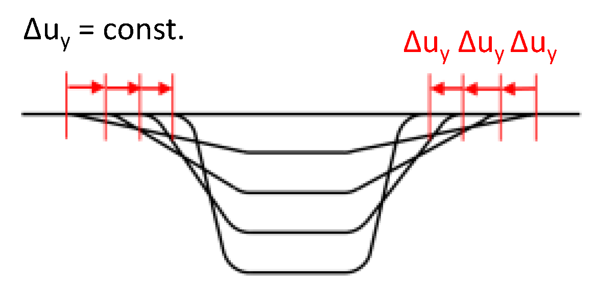
hmax,a describes the maximum profile height of the bottom curve and thus contains the highest risk of material thinning as a result of insufficient lateral material inlet. With the distance between the blank holders remaining unaltered during all roll passes, plastic stretching (Figure 8a) and the forming of multiple bending edges (Figure 8b) is expected. The adjustment of the blank holder roll sets for each roll pass makes sure that the material length in the cross-section of hmax,a remains consistent and is equivalent to the material length needed in the target geometry (Figure 8c). This approach supports the material inlet and reduces the risk of sheet stretching.
By analyzing the effect of the forming sequences on the geometric accuracy various strategies are considered:
Additionally, a distinction regarding the bending radii at each roll pass was made. In the first approach, the bending radii of the upper and lower bending edges remain unchanged (Figure 12a). The upper bending radius was defined by the edge radius of the lower blank holder rolls and the lower bending radius was given by the edge radius of the upper forming roller.
Alternatively, the bending radii can be adapted to the bending sequence so that the bending arc length remains constant for each roll pass (Figure 12b). In real experiments this means that custom-made lower blank holder rolls and upper forming rollers need to be manufactured and re-tooled before every roll pass. The implementation is not practicable in reality and conflicts with the basic idea of flexible manufacturing. Even so, for the purpose of process understanding this approach is investigated.
3. Results and Discussion
To determine the process limits and to derive optimization measures on the process or tooling side, a fundamental understanding of the appearing stress condition during the forming process needs to be built. For this purpose, numerical investigations were carried out by means of the model presented in Section 2.2 and a workpiece consisting of DC04 material. The results of the numerical analyses are presented hereafter.
The stress distribution in the lateral direction along the transverse section during the process appears to be a superposition of tensile stresses and bending stresses (Figure 13). In the area of the bending edges, bending stresses are predominant, while tensile stresses prevail in the profile bottom and leg as well as in flange sections close to the upper bending edge. By exceeding a critical value, the tensile stresses lead to material stretching in the lateral direction, which causes sheet thinning and is therefore to be avoided.
In the transition zones, the length of the profile bottom is greater than in the original state. In order to obtain the intended height-varying profile geometry, longitudinal strains along the profile bottom are necessary. Accordingly, longitudinal stresses were intentionally introduced to the profile bottom during the process (Figure 14). To reduce the longitudinal stresses in the profile bottom, sharp height transitions are to be avoided.
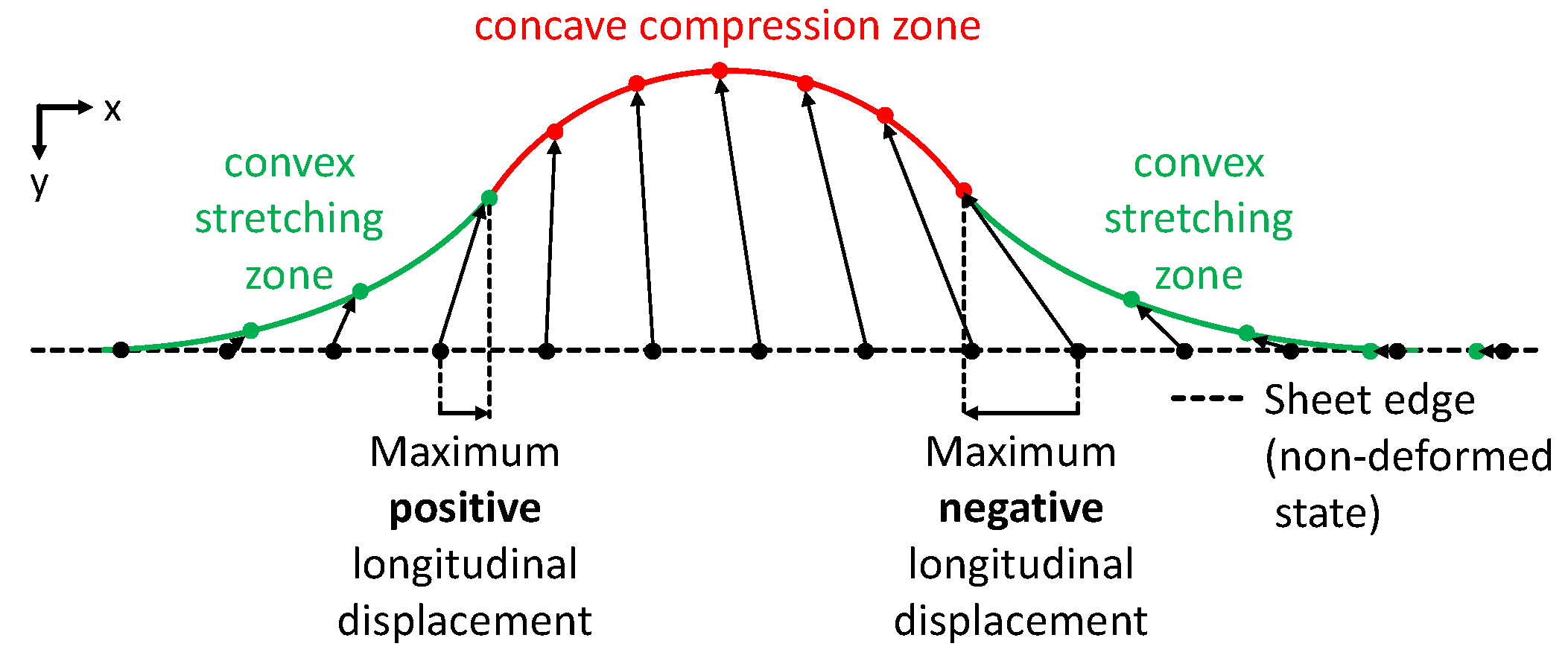
To avoid sheet stretching along the transverse sections lateral material inlet is intended. Subsequently, longitudinal stresses in the flanges and particularly along the sidewise profile edges occur. The deeper the profile depth, the more material has to be pulled in from the profile flanges. Consequently, the lateral displacement of the profile edge varies along the longitudinal direction. As a result, profile edge contours with convex and concave sections are formed. Depending on the either convex or concave shape of the profile edge section, local longitudinal displacements occur which lead to longitudinal stresses during the process (Figure 15).
The resulting displacements indicate that the material is not drawn in purely laterally. In convex zones, the displacement increases in the positive longitudinal direction while concave zones cause increasing displacements in the negative direction. The locations of the maximum positive and the maximum negative displacement border the compression zone asshown in Figure 16.
In sum, the dominant stress state during the process reveals lateral stretching and the presence of longitudinal compressive and tensile stress areas in the profile flange, which, by exceeding critical values, cause failure and geometric deviation. By selection of an appropriate forming strategy, the risk is to be minimized.
3.1. Process- and Tool-Side Variations: Effects of the Forming Sequence
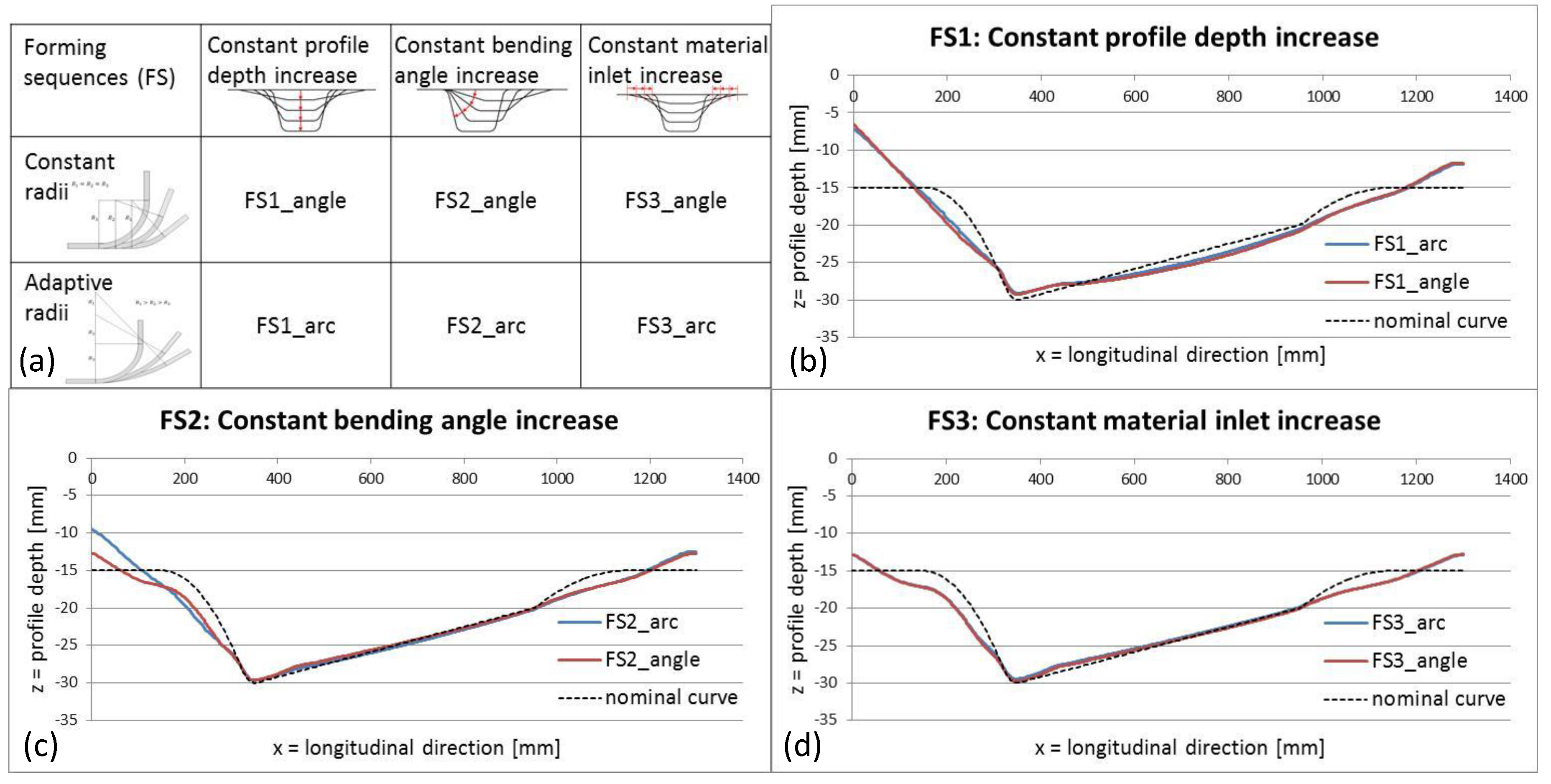
In Section 2.3, the different forming strategies and the two types of bending radii modification are presented. The combination of the forming strategies and the bending radii modification gives the selection of the considered forming sequences (Figure 17a). Figure 17 depicts the resulting profile bottom curves when applying the different forming sequences.
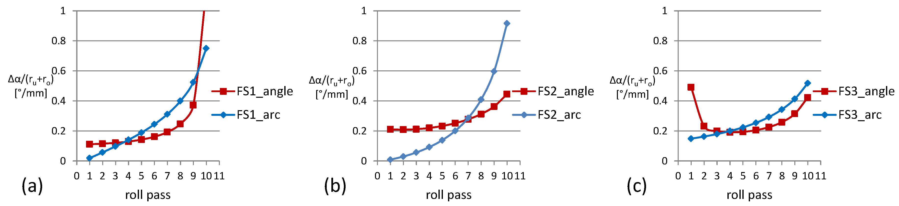
The nominal curve shows the striven target geometry. The profile bottom curves produced by the forming sequences FS2_angle, FS3_arc, and FS3_angle show a better accuracy. The impracticable approach of adapting the bending radii shows no improvement. The profile accuracy appears to be depending on the combination of the bending radii (upper bending radius ru, lower bending radius ro) and the bending angle increase ∆α of each roll pass. In Figure 18, the quotient of ∆α/(ru + ro) at x = 0 for each roll pass of the considered forming sequences is shown.
The forming sequences with larger deviations all have a strong increase of ∆α/(ru + ro) in the last the roll passes in common. Additionally, a large quotient in the first roll passes (FS3_angle) appears to have no negative effect on the geometric accuracy. Derived from the results, it can be noted that large increases of ∆α/(ru + ro) in the last roll passes are to be avoided. Compared to constant bending radii, the application of adaptive bending radii leads to an undesired reduction of ∆α/(ru + ro) in the first roll passes and an increase in the last roll passes. With regard to the results of FS2 in Figure 17c, where the largest deviation is observed, this effect is pronounced most significantly (Figure 19b).
Provided that ru and ro remain constant, ∆α can be set comparatively large during the first roll pass with a declining tendency through to the last.
3.2. Effect on the Sheet Thickness
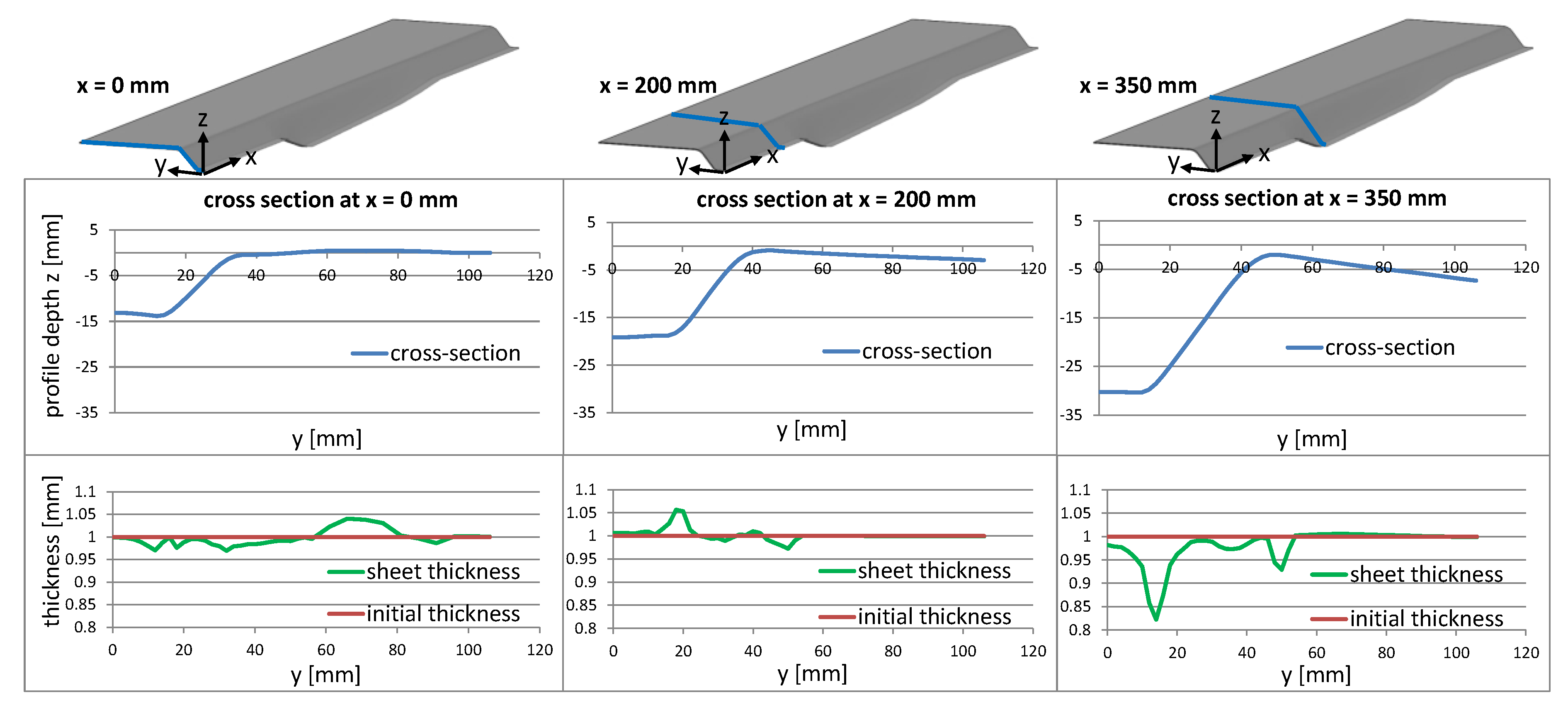
The largest deviations in the profile bottom curve appear in the section x = 0–350 mm. In the following, the resulting profile of the forming sequence with constant bending angle increase and constant bending radii (FS2_angle) is examined. The effect of the partly exceeded and subjacent profile depths on the material thickness is investigated along the cross-sections at x = 0 mm, 200 mm, and 350 mm, which is the location of maximum profile depth (Figure 20).
At x = 0 mm, areas with both marginal sheet thinning and thickening are observed. The sheet thinning is caused by the occurring tensile stresses along the cross-section (Figure 13). The thickening is a result of the blank holder roll set adaption (Figure 8c). By changing the lateral distance between the blank holder roll sets, the profile width is adjusted so that the material amount at the position with maximum profile depth (hmax,a) is kept constant for each roll pass. As a consequence, the remaining transverse sections contain surplus material which is pushed back into the flange in the course of the following roll passes. This material return creates local compressive stresses which lead to the observed material thickening. Such areas of thinning and thickening appear at x = 200 mm as well. Even though the maximum thickness is larger, the total thickness increase is lower than at x = 0 mm. Since the profile depth is greater at x = 200 mm, a lower amount of material needs to be returned to the flange, whereby lower compressive stresses occur. The cross-section at x = 350 mm contains no surplus material that needs to be pushed back which is why no sheet thickening is observed. Yet material thinning occurs in the bending edges, in the lower bending edge particularly since the lower bending radius (6 mm) is smaller than the upper radius (12 mm). This material thinning indicates that the lateral material inlet is impeded by the bending edges. As a result, the necessary material is obtained from the areas with the highest plastification, which are the bending edges. Figure 21 shows the diminishing material thickness with progressing roll passes and the correlation with the increasing difference between the desired and the actual material inlet.
3.3. Workpiece-Side Variations
Besides the influence of forming sequence design, the impact by varying workpiece properties is significant. Workpiece properties can be divided into geometric and material properties.
3.3.1. Geometric Properties: Workpiece Thickness
To examine the influence of the DC04 workpiece thickness, the same roll pass is performed on a sheet blank with 1.0 mm and 0.5 mm. The results demonstrate that, with decreasing workpiece thickness, identical tool motions achieve larger profile depths (Figure 22).
When regarding the stress and strain distribution during the process, it is evident, that the additionally gained profile depth is not a result of advantaged lateral material inlet but of material stretching. Figure 23 depicts the comparison of the lateral stress distributions along the transverse section at the position of maximum depth (hmax,a) of the considered blanks with different material thicknesses.
3.3.2. Material Properties
The influence of material variation was investigated by performing the same forming sequence on a DC04-steel and an Al2024 blank with identical dimensions. The resulting profile bottoms and plastic strain along the cross-section at the position of maximum profile height hmax,a is shown in Figure 24.
The profile bottom curve of the Al2024 workpiece showed an improved geometric accuracy compared to the DC04 blank, while the lateral strain increased marginally. The decisive explanation for the achievement of larger profile depths is the improved lateral material inlet during the first roll passes. Figure 25 depicts the lateral material inlet and the longitudinal stress in the profile edge at the same moment of the first roll pass.
The larger elastic region of the Al2024 material results in less plastic deformation and strain hardening in the bending edges during the initial roll passes. This benefits the lateral material flow leading to significantly increased material inlet (Figure 25a). The positive effect of the enhanced lateral material inlet outweighs the larger springback recovery of the Al2024 material, which results in an improved size accuracy. As a consequence of increasing material inlet, the accordingly increasing longitudinal stress in the profile edge (Figure 25b) enhances the risk of wrinkles. As a counter measure, additional roll passes can be performed in total to reduce the material inlet for each roll pass.
4. Conclusions
In the context of the presented research, the stress and strain distribution during the process “flexible roller beading” has been identified and understood. The potential component error patterns and their cause have been determined. The challenge of process design is the unification of opposing guidelines. Longitudinal elongation of the profile bottom is necessary for the manufacturing of the target geometry and therefore indispensable. To reduce the longitudinal stresses in the profile, bottom sharp height-transition zones should be avoided in the component design. During the process, lateral tensile stresses are to be minimized in order to avoid plastic elongation, and relating thereto, material thinning. To prevent the tensile stresses from exceeding the critical value, the lateral material inlet must be enhanced. A significant dependence between the material choice and the material inlet is shown. The material inlet is associated with the appearance of stretching and compression zones in the profile edges and flanges, which can cause component failure in the form of sheet wrinkles. The compression zones are caused by non-pure lateral displacement of the material in the profile flanges. In order to avoid the forming of convex–concave profile edge contours and reinforce a uniform material inlet, tailored workpieces are conceivable. By using customized semi-finished blanks, the necessary material for the height-variable profile is accordingly provided. By performing additional roll passes and thusly reducing the degree of deformation per step, the compressive stresses can be further reduced. In the design of the forming sequence, large increases of the bending angle, during the last roll passes particularly, are to be avoided to improve the geometric accuracy of the profile bottom curve. With regard to the findings obtained in the presented work, process optimization measures can be derived and applied to the experimental setup and experiment design. By means of the identified influence of process-, tool-, and workpiece-side variations, corresponding process adaption can be actioned when faced with varying process conditions. The overarching objective of the presented and future work is the determination of process limits and the reliable derivation of forming sequences to obtain individually customized height-variable profiles. By accomplishing these objectives, a highly flexible, industrial-suited sheet metal profile forming process, which allows on-demand manufacturing of light-weight profiles, can be introduced.
Author Contributions
Conceptualization, T.W. and P.G.; methodology, T.W.; software, T.W.; validation, T.W.; formal analysis, T.W.; investigation, T.W.; resources, P.G.; data curation, T.W.; writing—original draft preparation, T.W. and P.G.; writing—review and editing, P.G. and T.W., visualization, T.W., supervision, P.G., project administration, P.G.; funding acquisition, P.G.
Funding
This research was funded by the German Research Foundation (DFG), grant number GR1818_53-1 “Production of Multi-Directional Widened Profiles”.
Conflicts of Interest
The authors declare no conflict of interest. The funders had no role in the design of the study; in the collection, analyses, or interpretation of data; in the writing of the manuscript, or in the decision to publish the results.
References
- Schwab, K. The Fourth Industrial Revolution; Crown Business: New York, NY, USA, 2017. [Google Scholar]
- Yang, D.Y.; Bambach, M.; Cao, J.; Duflou, J.R.; Groche, P.; Kuboki, T.; Sterzing, A.; Tekkaya, A.E.; Lee, C.W. Flexibility in metal forming. In CIRP Annals—Manufacturing Technology; Elsevier Ltd.: Amsterdam, The Netherlands, 2018; pp. 743–762. [Google Scholar]
- Mehrabi, M.G.; Ulsoy, A.G.; Koren, Y.; Heytler, P. Trends and perspectives in flexible and reconfigurable manufacturing systems. J. Intell. Manuf. 2002, 13, 135–146. [Google Scholar] [CrossRef]
- Allwood, J.M. Steel and Aluminium in a Low Carbon Future. In Proceedings of the 10th International Conference on Technology of Plasticity, ICTP 2011, Aachen, Germany, 25–30 September 2011; pp. 27–42. [Google Scholar]
- Broer, G.; Martin-Bullmann, R. Kaltprofile; Verlag Stahleisen mbH: Düsseldorf, Germany, 1993. [Google Scholar]
- Groche, P.; Von Breitenbach, G.; Jockel, M.; Zettler, A. New Tooling Concepts for Future Roll Forming Applications. In Proceedings of the ICIT, 4th International Conference on Industrial Tools, Celje, Slovenia, 10–12 December 2003; pp. 121–126. [Google Scholar]
- Ona, H.; Sho, R.; Nagamachi, T.; Hoshi, K. Development of Flexible Cold Roll Forming Machine Controlled by PLC. In Steel Research International; WILEY-VCH: Weinheim, Germany, 2010; pp. 182–185. [Google Scholar]
- Lindgren, M.; Ingmarsson, L.-O. 3D roll forming of hat-profile with variable depth and width. In Proceedings of the 1st International Congress on RollForming, Bilbao, Spain, 14–15 October 2009; pp. 1–8. [Google Scholar]
- Sedlmaier, A.; Dietl, T.; Harrasser, J. 3D Roll Forming in Automotive Industry. In Proceedings of the 5th International Conference on Steels in Cars and Trucks, Amsterdam, The Netherlands, 18–22 June 2017. [Google Scholar]
- Groche, P.; Storbeck, M.; Wang, T. Continuous forming of height-variable beads by flexible roller beading. J. Adv. Manuf. Technol. 2019. under review. [Google Scholar]
- Berner, S.; Storbeck, M.; Groche, P. A Study on Flexible Roll Formed Products Accuracy by Means of FEA and Experimental Tests. In Proceedings of the 14th International ESAFORM Conference on Material Forming, AIP Conference Proceedings, Belfast, Northern Ireland, 27–29 April 2011; pp. 345–350. [Google Scholar]
- Groche, P.; Zettler, A.; Berner, S.; Schneider, G. Development and verification of a one-step-model for the design of flexible roll formed parts. Int. J. Mater. Form. 2011, 4, 371–377. [Google Scholar] [CrossRef]
- Park, J.C.; Yang, D.Y.; Cha, M.H.; Kim, D.G.; Nam, J.B. Investigations of a new incremental counter forming in flexible roll forming to manufacture accurate profiles with variable cross-sections. Int. J. Mach. Tools Manuf. 2014, 86, 68–80. [Google Scholar] [CrossRef]
- Kiuchi, M.; Koudabashi, T. Automated design system of optimal roll profiles for cold roll forming. In Proceedings of the 3rd International Conference on Rotary Metalworking Processes, Kyoto, Japan, 8–10 September 1984; pp. 423–436. [Google Scholar]
- Rebelo, N.; Nagtegaal, J.C.; Taylor, L.M.; Passman, R. Comparison of implicit and explicit finite element methods in the simulation of metal forming processes. In Proceedings of the ABAQUS Users Conference, Newport, Rhode Island, 1 January 1992. [Google Scholar]
- Senanayake, R.S.; Cole, I.M.; Thiruvarudchelvan, S. The application of computational and experimental techniques to metal deformation in cold roll forming. J. Mater. Process. Technol. 1994, 45, 155–160. [Google Scholar] [CrossRef]
- Daniel, W.J.T.; Meehan, P.A. Implicit finite element study of non-steady effects in cold roll forming. In Proceedings of the 5th Australasian Congress on Applied Mechanics (ACAM 2007), Brisbane, Australia, 10–12 December 2007. [Google Scholar]
- Groche, P.; Mueller, C.; Traub, T. Experimental and Numerical Determination of Roll Forming Loads; Wiley: Weinheim, Germany, 2013; pp. 112–122. [Google Scholar]
- MARC. User Information—Volume A, Element Library—Volume B; MARC Analysis Research Corporation: Palo Alto, CA, USA, 2014. [Google Scholar]
- Gehring, A. Beurteilung der Eignung von Metallischem Band und Blech zum Walzprofilieren. Ph.D. Thesis, Universitätsverlag Karlsruhe, Karlsruhe, Germany, 2006. [Google Scholar]
- Traub, T.; Miks, C.; Groche, P. Force Measurements Supporting the Set-up Process in Roll Forming. In Proceedings of the 1st Annual International Conference on Mechanical Engineering, ATINER’s Conference Paper Series, MEC2017-2346, Athens, Greece, 17–20 July 2017. [Google Scholar]
- Boman, R.; Papeleux, L.; Bui, Q.V.; Ponthot, J.P. Application of the Arbitrary Lagrangian Eulerian formulation to the numerical simulation of cold roll forming process. J. Mater. Process. Technol. 2006, 177, 621–625. [Google Scholar] [CrossRef]
- Görtan, M.O.; Vucic, D.; Groche, P.; Livatyali, H. Roll forming of branched profiles. J. Mater. Process. Technol. 2009, 209, 5837–5844. [Google Scholar] [CrossRef]
Figure 1.
Characteristics and nomenclature of the target geometry.

Figure 2.
Process principle and degrees of freedom of a flexible roller beading stand.

Figure 3.
Flexible roller beading system.

Figure 4.
Experimental results: (a) manufactured profile bottom curve; (b) picture of the manufactured profile.
Figure 4.
Experimental results: (a) manufactured profile bottom curve; (b) picture of the manufactured profile.

Figure 5.
(a) Mesh properties and (b) material flow curves of DC04 and Al2024.

Figure 6.
(a) Numerical model with two roll passes, (b) sheet fixing boundary conditions, and (c) deformed profile.
Figure 6.
(a) Numerical model with two roll passes, (b) sheet fixing boundary conditions, and (c) deformed profile.

Figure 7.
Geometric characteristics of the target profile bottom curve.

Figure 8.
Blank holder roll set adaption: (a) risk of sheet stretching without adaption, (b) risk of multiple bending without adaption, and (c) principle of blank holder roll set adaption.
Figure 8.
Blank holder roll set adaption: (a) risk of sheet stretching without adaption, (b) risk of multiple bending without adaption, and (c) principle of blank holder roll set adaption.

Figure 9.
Forming sequence with constant profile depth increase in each roll pass.

Figure 10.
Forming sequence with constant bending angle increase in each roll pass.

Figure 11.
Forming sequence with constant lateral material inlet increase in each roll pass.

Figure 12.
(a) Constant bending radii in each roll pass, and (b) constant bending arc length in each roll pass.
Figure 12.
(a) Constant bending radii in each roll pass, and (b) constant bending arc length in each roll pass.

Figure 13.
Lateral stresses along a transverse section of the profile during the process.

Figure 14.
Longitudinal stresses along the profile bottom during the process.

Figure 15.
Displacement and longitudinal stresses along the profile edge during the process.

Figure 16.
Displacement paths of the concave/convex shaped profile edge.

Figure 17.
Forming strategies and the resulting profile bottom contours.

Figure 18.
∆α/(ru + ro) at each roll pass of the forming sequences.

Figure 19.
Effect of adapting the bending radii to ensure constant bending arc length on ∆α/(ru + ro).
Figure 19.
Effect of adapting the bending radii to ensure constant bending arc length on ∆α/(ru + ro).

Figure 20.
Sheet thicknesses in the cross-sections at x = 0, 200, 350 mm.

Figure 21.
Correlation between material thinning and insufficient lateral material inlet.

Figure 22.
Resulting profile bottom curves with workpiece thickness variation.

Figure 23.
(a–b) Lateral stress and (c) strain along the cross-section at x = 350 mm (hmax,a) for sheet metal thicknesses 1.0 mm and 0.5 mm.
Figure 23.
(a–b) Lateral stress and (c) strain along the cross-section at x = 350 mm (hmax,a) for sheet metal thicknesses 1.0 mm and 0.5 mm.

Figure 24.
(a) Profile bottom curves and (b) lateral strain along the cross-section at x = 350 mm of a DC04 and Al2024 sheet blank.
Figure 24.
(a) Profile bottom curves and (b) lateral strain along the cross-section at x = 350 mm of a DC04 and Al2024 sheet blank.

Figure 25.
Material inlet (a) and longitudinal stress in the profile edge (b) of the DC04 and Al2024 blanks.
Figure 25.
Material inlet (a) and longitudinal stress in the profile edge (b) of the DC04 and Al2024 blanks.

© 2019 by the authors. Licensee MDPI, Basel, Switzerland. This article is an open access article distributed under the terms and conditions of the Creative Commons Attribution (CC BY) license (http://creativecommons.org/licenses/by/4.0/).
Share and Cite
MDPI and ACS Style
Wang, T.; Groche, P. Sheet Metal Profiles with Variable Height: Numerical Analyses on Flexible Roller Beading. J. Manuf. Mater. Process. 2019, 3, 19. https://doi.org/10.3390/jmmp3010019
AMA Style
Wang T, Groche P. Sheet Metal Profiles with Variable Height: Numerical Analyses on Flexible Roller Beading. Journal of Manufacturing and Materials Processing. 2019; 3(1):19. https://doi.org/10.3390/jmmp3010019
Chicago/Turabian StyleWang, Tianbo, and Peter Groche. 2019. "Sheet Metal Profiles with Variable Height: Numerical Analyses on Flexible Roller Beading" Journal of Manufacturing and Materials Processing 3, no. 1: 19. https://doi.org/10.3390/jmmp3010019