Article

Microstructural and Mechanical Properties of AZ31B to AA6061 Dissimilar Joints Fabricated by Refill Friction Stir Spot Welding

by
Venukumar Sarila
1,
Harisivasri Phanindra Koneru
2,
Muralimohan Cheepu
3,4,*,
Bharat Kumar Chigilipalli
5,
Venkata Charan Kantumuchu
6 and
Muthukumaran Shanmugam
7
1
Department of Mechanical Engineering, Vardhaman College of Engineering, Hyderabad 501218, Telangana, India
2
Department of Mechanical Engineering, Vel Tech Rangarajan Dr. Sagunthala R&D Institute of Science and Technology, Chennai 600062, Tamil Nadu, India
3
Department of Materials System Engineering, Pukyong National University, Busan 48572, Korea
4
Super-TIG Welding Co., Ltd., Busan 46722, Korea
5
Department of Production Engineering, National Institute of Technology, Tiruchirappalli 620015, Tamil Nadu, India
6
Electrex Inc., Hutchinson, KS 67501, USA
7
Department of Metallurgical and Materials Engineering, National Institute of Technology, Tiruchirappalli 620015, Tamil Nadu, India
*
Author to whom correspondence should be addressed.
J. Manuf. Mater. Process. 2022, 6(5), 95; https://doi.org/10.3390/jmmp6050095
Submission received: 9 July 2022 / Revised: 17 August 2022 / Accepted: 22 August 2022 / Published: 30 August 2022
(This article belongs to the Special Issue Advances in Friction Stir Welding in the Light of Industry 4.0)

Abstract

:
Dissimilar friction stir spot welds (FSSW) between the magnesium and aluminum alloys are joined, using a novel approach called refill friction stir spot welding. The present work aims to evaluate the macrostructural and mechanical properties of refill friction stir spot welded AZ31B and AA 6061-T6 alloys in two combinations, i.e., identical Mg-to-Mg and dissimilar Mg-to-Al joints, and the results are compared with the results obtained in conventional friction stir spot welding. The hardness profiles of the similar welds had the appearance of a W-shape, and the Thermo mechanically affected zone and heat-affected zone of both methods had lower hardness values than the rest of the weld. Along with the interface between the aluminum and magnesium sheets, a thin intermetallic compound layer of Al12Mg17 has been identified, which has led to an increase in hardness. The static shear strength of both similar and dissimilar refill spot friction welds was much greater than that of traditional spot friction welds. In both similar and dissimilar spot friction welds, two distinct failure scenarios are discovered.

1. Introduction

Magnesium and aluminum alloys are widely employed in sophisticated manufacturing industries due to their environmental friendliness, high specific strength, low density, and superior damping capacity. In the 21st century, these materials are utilized extensively in the aerospace and missile, automobile, construction, and electronic communications industries. Currently, Al/Mg alloy joining technologies are gaining popularity. Friction stir spot welding (FSSW), a well-known solid-state technology as an alternative to RSW or rivet fastening for joining aluminum alloys, has recently been applied to join dissimilar junctions made from aluminum and magnesium [1,2,3]. The friction stir welding (FSW) process produces key hole defects during the welding process, whereas the spot welding (SW) process produces pores and solidification cracks during the welding process [4,5]. Along with the FSW, other processes are also made to develop dissimilar welds using multi-materials [6,7,8,9,10]. The challenges, interface characteristics, and intermetallic formation of the joints are studied in detail [11,12,13,14,15,16]. However, FSSW takes both the advantages of FSW and SW processes. The melting and solidification defects associated with spot welding processes can be eliminated using FSSW. Refill friction stir spot welding (R-FSSW) is a relatively new technology for producing without a keyhole during spot joints. Thus, the R-FSSW joint exhibits more joint strength than conventional friction stir spot welding (C-FSSW) [17,18,19].
Choi et al. [20] studied the effects of welding parameters on the joining of AA 6K21 and MA AZ31 plates by employing various tool rotation speeds and tool duration periods. The intermetallic layer becomes thicker as the tool rotation speed and duration time increase, which has a substantial impact on the joint strength. Chowdhury et al. [21] examined the fatigue characteristics and shear strength of spot friction stir welded dissimilar aluminum alloy and magnesium alloy in three combinations: (top) Al/Mg (bottom), Al/Mg with an adhesive interlayer, and Mg/Al with an adhesive interlayer. The stir zone (SZ) was found to consist of intermetallic compounds of Al3Mg2 and Al12Mg17 for all dissimilar weld combinations, enhancing hardness. Shen et al. [22] explored the effects of different lap configurations and preheating methods on the macrostructures and mechanical properties of spot friction stir welds using similar and dissimilar (AA 6061-T6 and Mg AZ31B) materials. Chai et al. [23] evaluated the influence of sleeve plunge depth on joint microstructure and mechanical parameters for dissimilar 5083 Al/AZ31B alloys that were connected using refill friction stir spot welding (R-FSSW). Wu et al. [24] utilized the swing friction stir spot welding (S-FSSW) technology to join Al alloy to Mg alloy in two steps, in addition to C-FSSW. In S-FSSWed joints, the intermetallic compound (IMC) structure in the interface layer is spherical, as opposed to the dendritic structure of typical FSSW joints [25].
In this study, a friction-forming tool is used to refill the pinhole rather than a costly and complex FSSW machine with a retractable pin tool device. A patent for the friction-forming process was issued in 2008 to one of the present authors [26]. The alloys AA 6061-T6 and Mg AZ31 have been chosen for conventional and refill FSSW. Using both conventional and refill FSSW, the microstructural and mechanical parameters of similar and different welds are investigated and compared.

2. Experimental Procedure

In this work, AZ31B and AA 6061-T6 sheets having 2 mm thickness were utilized. The chemical composition and tensile properties of the base materials are listed in Table 1 and Table 2, respectively. Length, width, and overlapping length are all 100 and 30 mm. All the welding experiments were carried out using a modified milling machine. In standard FSSW, the tool has a shoulder of 18 mm in diameter and a pin of 5 mm. Nonetheless, the refill FSSW has two types of tools: the standard FSSW tool and the friction-forming tool. The shoulder of the 18 mm-diameter friction-forming tools was utilized in the refilling procedure. The rotational rates of the tools were modified to 900, 1120, 1400, and 1800 rpm, and the experiment was repeated three times for each operation. Figure 1 shows a schematic representation of the R-FSSW procedure. Two lap weld plates are maintained on the backing block, and the complete assembly is secured in a specially designed die and held by a fixture. In the first two stages, welding is performed similarly to C-FSSW, as shown in Figure 1a,b. After the first two stages, when the pin is retracted, a keyhole is produced in the sheets. During the refilling procedure, a filler plate of the same material and thickness as the weld plates are put on the welded sample, and a revolving friction forming tool is used to provide compression force (see Figure 1c). Material from the filling plate is mixed and pressed into the keyhole under compression (see Figure 1d). In R-FSSW, the rotational speed of the tool is identical to that of C-FSSW. After welding, the MgAZ31B/ MgAZ31B similar and MgAZ31B/ AA6061-T6 dissimilar spot welds were sectioned at the weld center and analyzed with an optical microscope. Optical and scanning electron microscopes are used to characterize dissimilar weld joints. For observation of the weld microstructures, the specimens are etched with Poulton’s reagent (Composition: 30 mL HCl, 40 mL HNO3, 2.5 mL HF, 12 g CrO3, 42.5 mL H2O) for the Al alloy, and acetic picral (10 mL acetic acid (99%), 4.2 g picric acid, 10 mL H2O, 70 mL ethanol (95%)) for the Mg alloy. To acquire the hardness values, the Vickers microhardness test was performed for 20 s with a 500 g force on the cross-section of the FSSW samples. To establish the mechanical properties of the joint, a tensile shear test was conducted. The tensile shear test was utilized in order to ascertain the weld joint’s inherent mechanical properties. Tensile tests were carried out at room temperature using a tensile test machine, with the crosshead moving at a speed of one millimeter per minute.

3. Results and Discussion

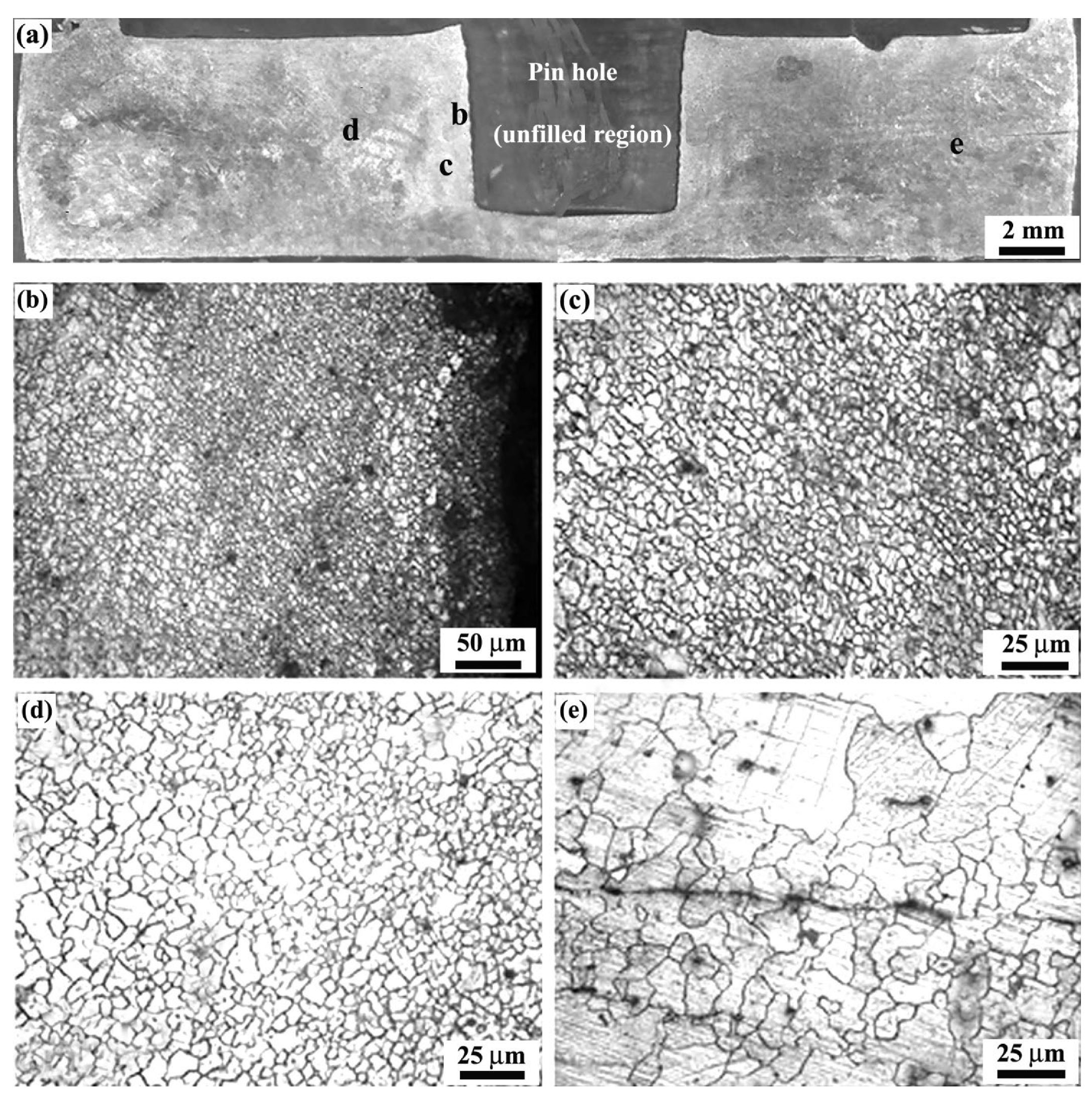
3.1. Similar Friction Stir Spot Welds in AZ31B Alloy Sheets

Both C-FSSW and R-FSSW techniques are used to join AZ31B alloy sheets. These sheets are utilized to produce overlap joints with varying tool rotational speeds. To better comprehend the microstructure produced by the FSSW method, one of the welds has been selected for microstructural evaluation. Figure 2a depicts the top view and macroscopic appearance of a cross-section of standard FSSW welds at 900 rpm tool rotational speed. A weld’s cross-section can be divided into four regions: stir zone (SZ), base material (BM), TMAZ, and HAZ [27]. The typical microstructures of these regions are depicted in Figure 2b–e. Although the HAZ is difficult to discern under an optical microscope, its presence is indicated by the hardness data. The SZ is distinguished by equiaxed fine grains, which are the result of dynamic recrystallization induced by intense plastic deformation and exposure to high temperatures during welding. The TMAZ is characterized by 14 µm grains that are elongated and orientated in a certain direction, as a result of the tool’s deformation. The BM microstructure is very heterogeneous and predominantly formed of grains with an average size of 19 µm.
Figure 3a depicts the top view and macroscopic appearance of the cross-section of welds produced by the R-FSSW approach with a convex profile at a tool rotating speed of 900 rpm. It is evident that the probe hole has been successfully refilled, and both sides of the welds have smooth surfaces. Using this method, weld flaws cannot be found anywhere, indicating proper material mixing in the weld center. This is because of its inherent convex profile, which fills the probe hole in the center. As demonstrated in Figure 3a, the effect of the convex tool profile may be observed in the macrostructure of R-FSSW samples. Figure 3b–d depicts high magnification images of the regions b–d indicated in Figure 3a. The cross-section is divided into three regions (Figure 3b–d) based on the characteristics of the FSSW joint’s cross-section: the SZ, the TMAZ, and the refill region. As demonstrated in Figure 3b, SZ is characterized by equiaxed fine grains due to dynamic recrystallization. Between the SZ and BM, the TMAZ has an elongated structure pointing upwards due to the 15 µm average grain size of its plastic deformation. The average grain size of the grains in the refilled region is 12 µm.

3.1.1. Microhardness

The indentations were made along each of the four parallel lines with a spacing of 0.4 mm in order to understand the hardness difference in various areas of the spot friction stir spot welds. Figure 4 depicts a typical hardness profile across similar AZ31B/AZ31B weldments produced with conventional FSSW and RFSSW at a tool rotational speed of 900 rpm. As illustrated in Figure 4, the microhardness profile across the weld exhibits higher values in the SZ and lower values in the HAZ and TMAZ. The increased hardness is likely the result of the decrease in grain size in the stir zone. The typical hardness of the base metal is around HV 68, whereas the SZ hardness varied between 89 and 91% to that of the BM hardness.

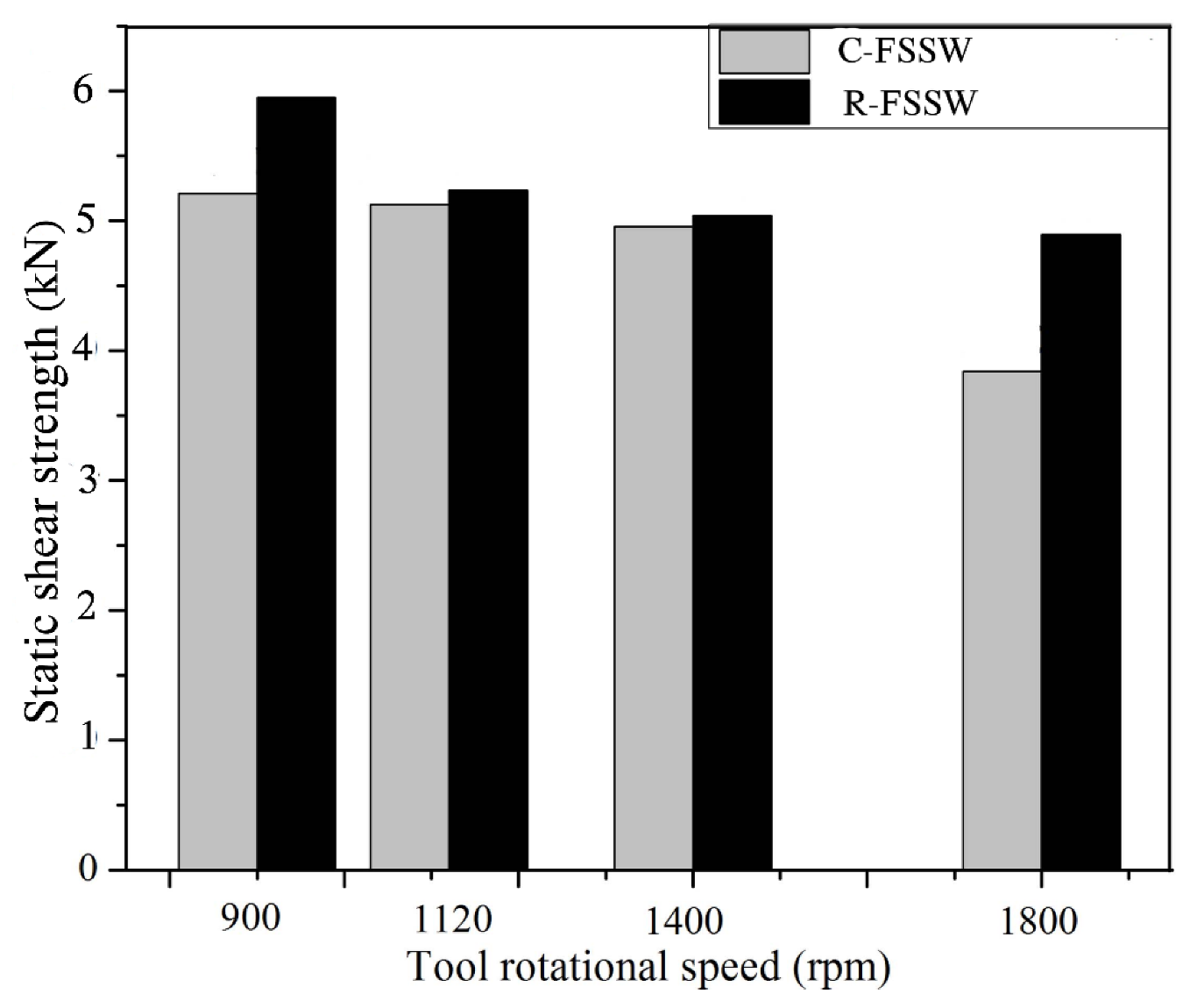
3.1.2. Tensile/Shear Tests
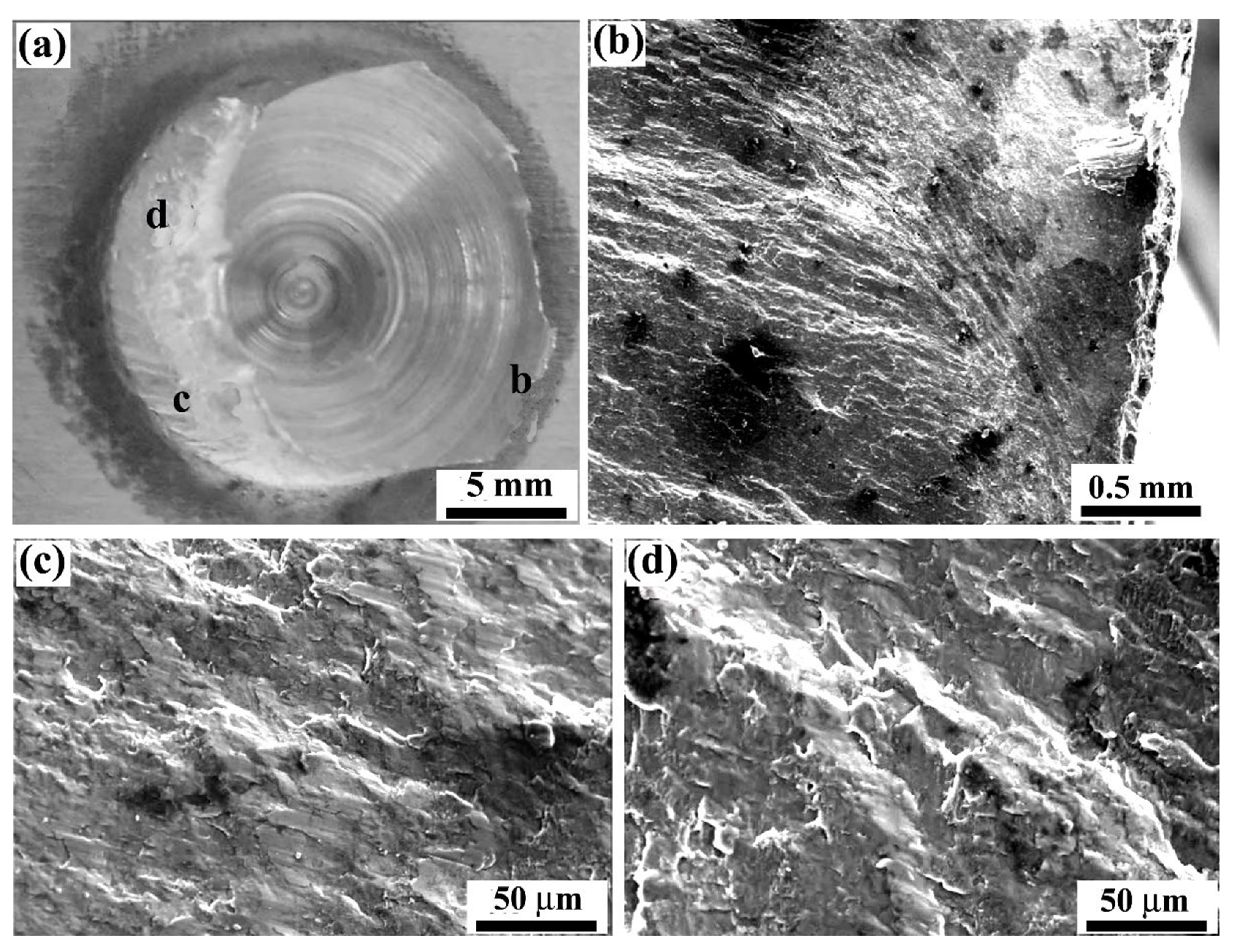
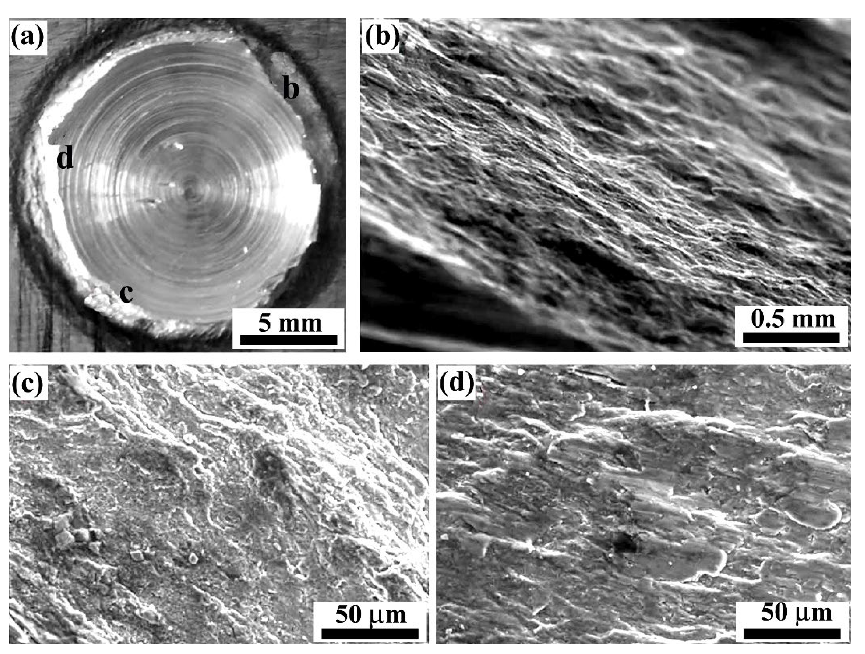
Figure 5 depicts the static shear strengths of welds produced by the C-FSSW and R-FSSW techniques. At all tool rotational rates, the R-FSSW process produces substantially stronger welds than the standard friction stir spot welding method. The increase in static shear strength in the R-FSSW technique is a result of the absence of a keyhole and the presence of additional material in the weld as a result of the addition of a filler plate. The additional material from the filler in the joint will provide a more compact pressure, resulting in an increased bonding, hence increasing the static shear strength, whereas the keyhole present in the conventional approach behaves as a notch during loading and creates excessive stress concentration. This would lead to the initiation and propagation of a crack, which would ultimately result in the material having poor mechanical qualities. The specimens all fractured in a nugget pullout mode when they were tested, and this was consistent for each and every weld that was made using the R-FSSW approach. In order to provide a point of reference, the C-FSSW was also performed using the same rotating tools under the exact same welding conditions. An increase in the rotating speed of the tool causes a drop in the static shear strength, which in turn causes the joints to fracture through a shear failure mode. The refilling process has the potential to improve the lower static shear strength that was observed when the tool rotational speed was 1800 rpm.
Under lap shear tests using the C-FSSW and R-FSSW methods, the close-up bottom views of the upper sheets and the close-up top views of the lower sheets are illustrated in Figure 6 and Figure 7, respectively. In both the C-FSSW and the R-FSSW processes, two distinct failure scenarios were discovered. From the C-FSSW specimens, shear fracture results in the material being sheared off at the probe hole’s periphery (Figure 6). It is due to the tool’s rotating speed of 1800 revolutions per minute (rpm), this type of fracture has been recorded. At other speeds, a portion of the nugget is retained in the lower sheet, as demonstrated in Figure 6. The majority of the weld nugget remained in the lower sheet following a nugget pullout fracture, as seen in Figure 6. However, the nugget pullout fracture is visible in the R-FSSW process at all speeds, as seen in Figure 7. This suggests that nugget pullout fracture results in greater bonding than shear fracture. Consequently, it has been determined that the static shear strength of weld samples produced with the R-FSSW process is greater than that of samples produced with the C-FSSW method.

3.1.3. SEM Analysis

Figure 8 depicts SEM images of a fracture surface for a C-FSSW specimen welded at 900 rpm tool rotating speed. Figure 8a depicts the macroscopic fracture surface of the top view of the lower sheet in close vicinity. Along the boundary between the upper and lower sheets near the edge of the probe hole, a shear fracture has occurred, and the faying surface between both the two sheets has been totally sheared off. The regions depicted in Figure 8a are magnified in Figure 8b–d accordingly.
Figure 9 depicts SEM images of the fractured surface found on the lower sheet of the R-FSSW process at 900 rpm tool rotation speed. Figure 9b–d depict the magnified images of points b–d from Figure 9a. Points b–d display the typical nugget pullout fracture surfaces with striation-like patterns, while point d reveals a static fracture surface with dimples. This suggests that the fracture developed around the nugget, with the final fracture occurring between points c,d.

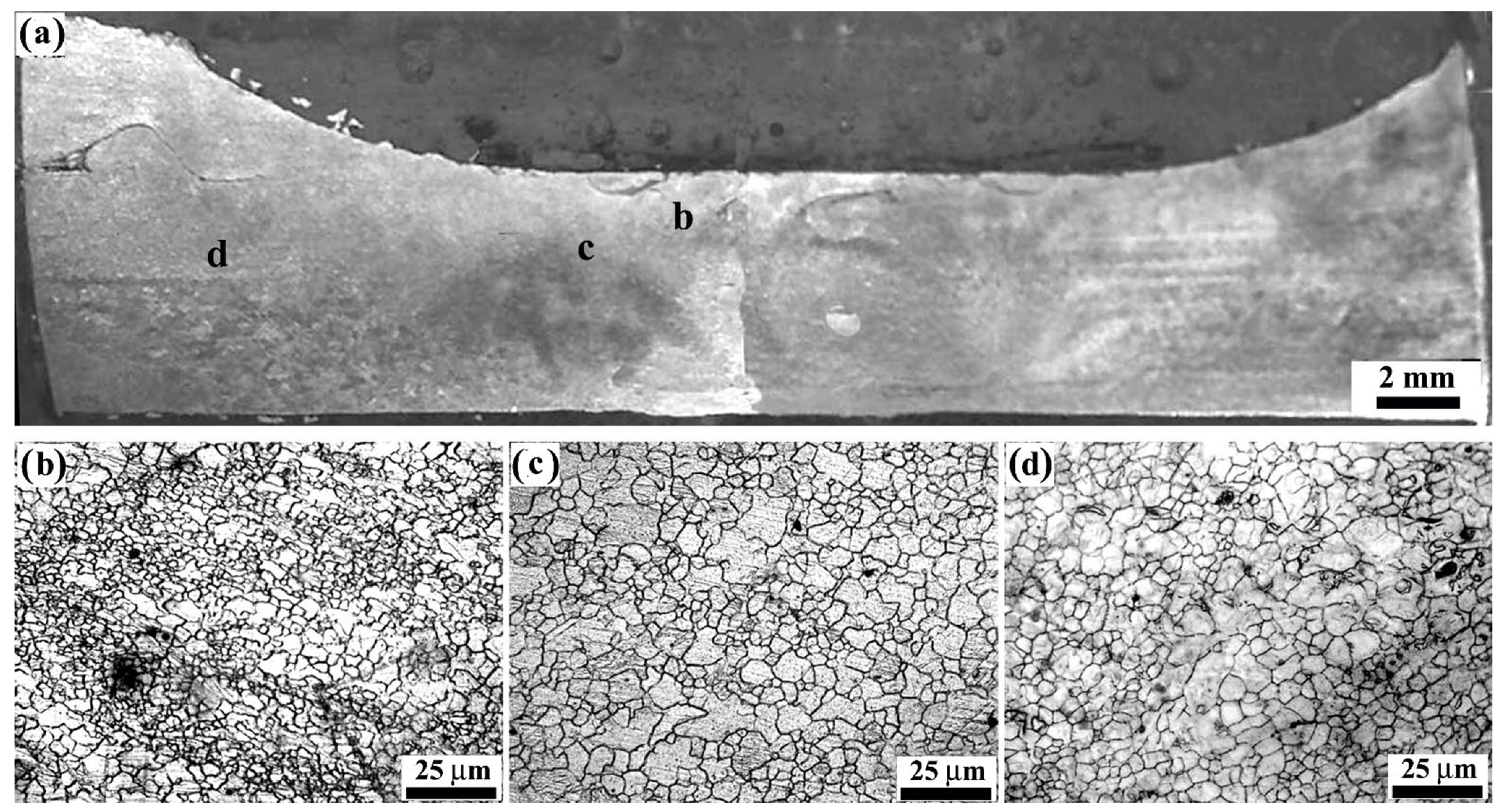
3.2. Dissimilar AZ31B/AA6061-T6 Alloys

In both the C-FSSW and R-FSSW processes, sheets of AZ31B Mg alloy and AA6061-T6 Al alloy were welded together, with the Mg alloy on top of the Al sheet. Figure 10a depicts a typical optical macrograph of the cross-section of a standard FSSW-created weld. No thickness reduction or probe hole is visible in the weld. Figure 10b,c depicts enlarged views of places highlighted in Figure 10a.
Figure 11a depicts the cross-section of the weld produced by the R-FSSW approach. Figure 11b,c depicts a magnified image of the interface between Mg and Al in the middle of the nugget. The EDS line analysis was conducted along the line in Figure 12a, and the findings are shown in Figure 12b. EDS investigation confirms the presence of both Mg and Al alloys along the line perpendicular to the contact, confirming the formation of an IMC. Using quantitative EDS area analysis, the IMC has been identified as Al12Mg17. The IMC layer is identified as a slightly brighter layer, and its thickness is estimated to be around 10 µm, as illustrated in Figure 12. In accordance with the Al-Mg phase diagram, the layers may be predominantly composed of an IMC of Al12Mg17 and Mg-rich Al. Constitutive liquification during FSSW causes the creation of such an IMC in Al/Mg dissimilar welds [21,27].

3.2.1. Microhardness

Figure 13 depicts the hardness distribution over the Mg/Al dissimilar welds produced by the R-FSSW. For the upper AZ31B Mg sheets in all welding processes, the HAZ has the lowest hardness value. Furthermore, there is a modest increase in hardness in the SZ region, which can be attributed to a reduction in grain size relative to other locations. As for the AA6061-T6 side, the base metal has a higher hardness than other places. The rapid rise in microhardness in the weld center is caused by the formation of brittle -Al12Mg17 intermetallics as depicted in Figure 12. The SZ in the Mg/Al welds has much greater hardness values, ranging from Hv 85 to Hv 135. Chowdhury et al. [18] reported comparable outcomes during the friction stir spot welding of dissimilar materials. Observed experimental results are consistent with previous studies [21].

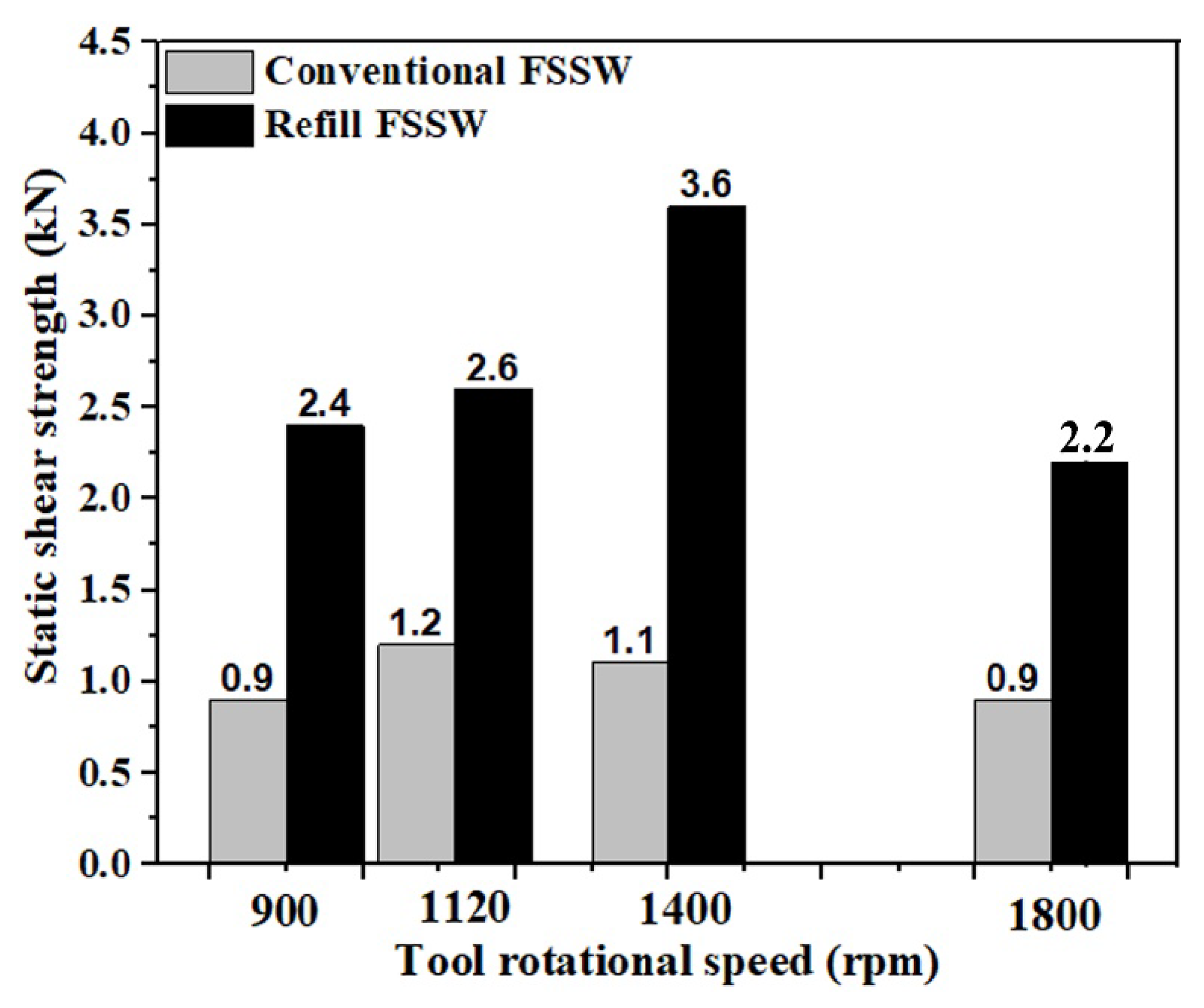
3.2.2. Tensile/Shear Tests
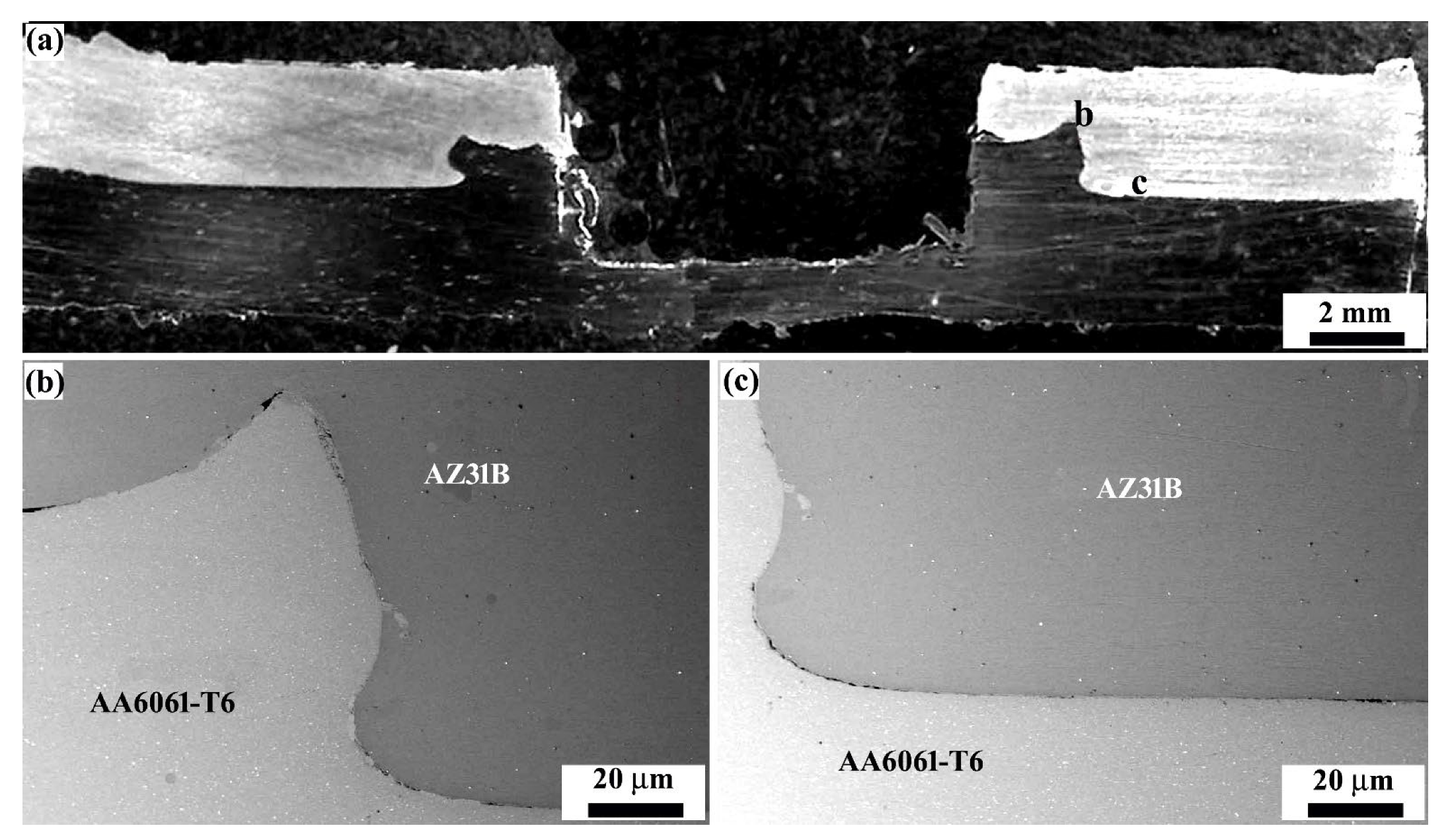
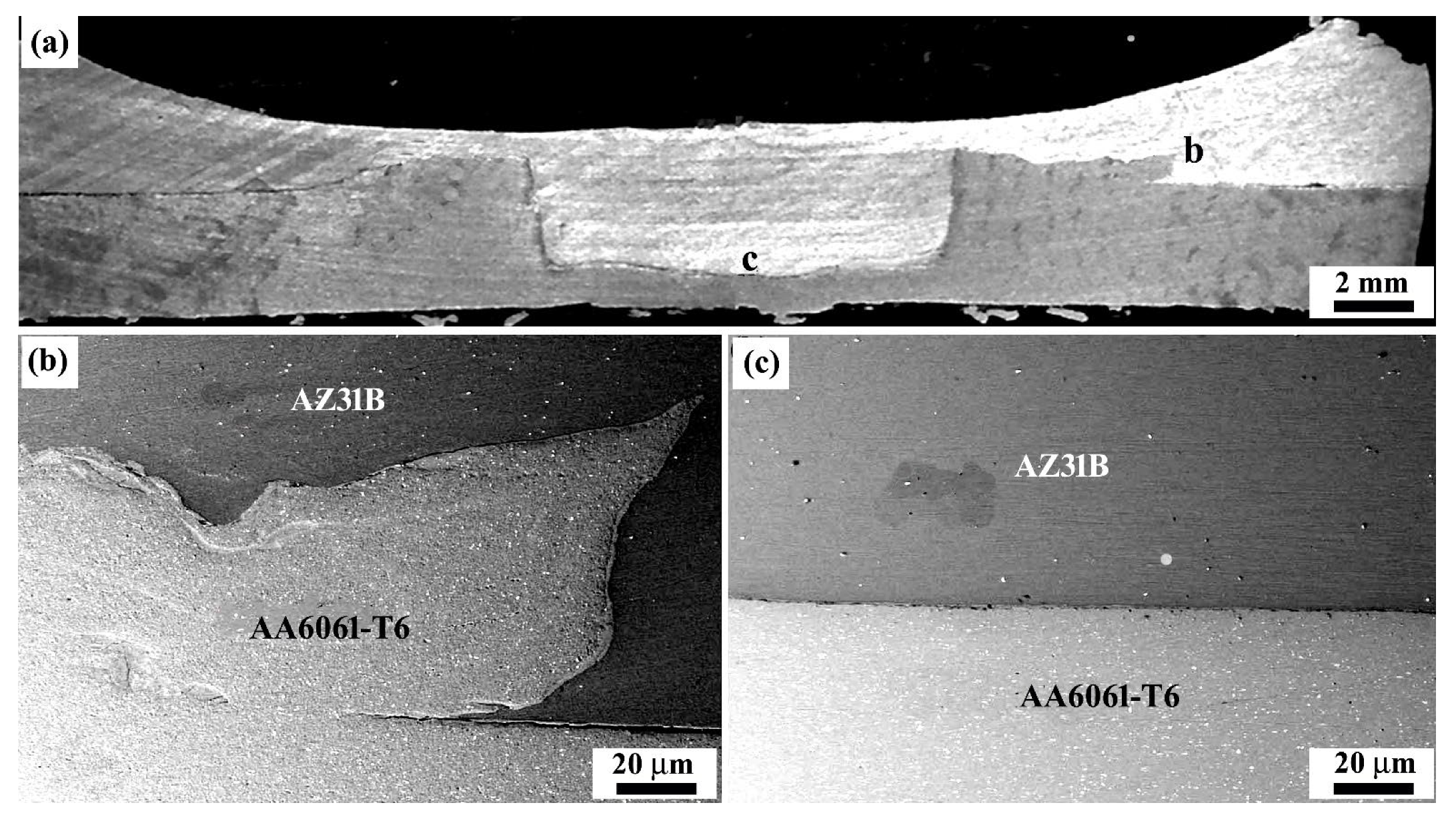
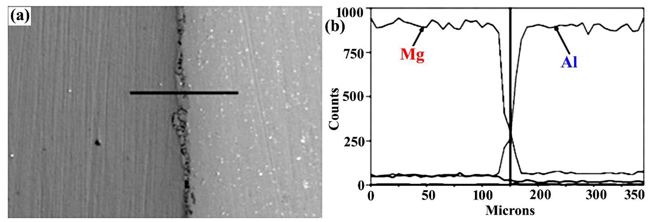
Figure 14 depicts the lap shear test results for the Mg/Al dissimilar welds produced by the C-FSSW and R-FSSW methods. At all tool rotational speeds, the R-FSSW method creates welds with greater static shear strength than C-FSSW. Nevertheless, the static shear strength of dissimilar joints is lower than that of joints made from similar materials, and all the weld joints were fractured at the interface. The increase in static shear strength without the presence of ductility during the R-FSSW approach is attributable to the absence of the keyhole and the presence of more material in the weld as a result of the addition of the filler plate. At a tool rotational speed of 1400 rpm, R-FSSW welds have the highest static shear strength of 3.6 kN. When the tool’s rotating speed exceeds 1400 rpm, the static shear strength of joints decreases. The static shear strength of joints decreases when the rotational speed of the tool exceeds 1400 rpm.
Figure 15 depicts the close-up bottom views of the upper sheets and the close-up top views of the lower sheets during lap shear testing for the C-FSSW and R-FSSW processes. At all the speeds, the shear fracture mode of failure is found in C-FSSW weld samples, whereas in the R-FSSW process, the nugget pullout fracture is observed at all speeds. Regardless of the fracture mechanism, crack initiation always begins in the region of incomplete bonding. As the shear force on the weld sample increases, the crack propagates throughout the zone that is fully bonded. When the maximum load is applied, the fracture takes place, consequently destroying the bonding between the sheets. In C-FSSW, Figure 15 demonstrates that the shear fracture occurred through the interface between the upper and lower sheets.
Consequently, it is believed that the creation of the IMC layer led to the bonding of the upper and lower sheets, whereas nugget debonding failure was found for all RFSSW specimens. According to Figure 15, the majority percentage of magnesium remains in the lower sheet. This suggests that the nugget pullout fracture exhibited greater bonding than the shear fracture. Additionally, IMCs were identified at the interface of the weld joint. In contrast, the creation of IMCs has no effect on the static shear strength of the welds, as all of the welds fragmented via the nugget pull-out mode rather than the shear fracture mode. Thus, it has been determined that the static shear strength of weld samples produced with the R-FSSW process is greater than that of samples produced with the C-FSSW procedure.

3.2.3. SEM Analysis

Figure 16 depicts the SEM images of a fractured surface on the R-FSSW specimen at a tool rotational speed of 1400 rpm. Figure 16a depicts the fracture surface from the top view of the aluminum side. Figure 16b–d depicts the magnified views of points b–d in Figure 16a. As depicted in Figure 16a, the fracture propagates from the original crack tip near the unwelded joint interface, slightly upwards, and then along the border of the refilled probe hole. Thereby, the R-FSSW approach is used successfully in the dissimilar welding of AZ31B Mg alloy to 6061-T6 Al alloy. The probe hole, which is made during C-FSSW, can be successfully avoided and the mechanical properties of the joints can be enhanced by welding the probe hole, which is created during conventional F-SSW. The SZ of the Mg/Mg comparable weld exhibits grain refinement, while the TMAZ and HAZ exhibit partial recrystallization.
The production of the Al12Mg17 intermetallic compound characterizes the Mg/Al dissimilar weld. Similar Al/Al and Mg/Mg welds displayed a W-shaped microhardness profile during both the conventional and refill FSSW methods. Minimum hardness values were observed in the TMAZ and HAZ of comparable Mg/Mg and Al/Al welds produced by both methods. Due to the formation of intermetallic (a hard and brittle structure), the SZ of Mg/Al welds have much higher hardness values, ranging between 85 HV and 135 HV. It has been determined that the Mg/Al dissimilar weld has a lower static shear strength than the Al/Al and Mg/Mg similar welds. In addition, the static shear strength of the Mg/Al dissimilar weld produced by the R-FSSW technique is greater than that of the C-FSSW process at all tool rotating speeds. Due to the development of IMCs, the shear fracture has been seen in Mg/Al dissimilar welds produced by the C-FSSW technique. In addition, a nugget pull-out fracture was discovered during the R-FSSW process.

4. Conclusions

By using C-FSSW and R-FSSW process, similar Mg/Mg and dissimilar Mg/AA alloys were effectively bonded. Overall, R-FSSW-joined Mg/AA dissimilar welds have a higher static shear strength than conventional dissimilar Mg/AA and similar Mg/Mg welds. This can be attributed to the absence of keyholes and the insertion of filler plate material into the weld. The hardness profiles of similar welds were W-shaped, with the TMAZ and HAZ of both methods exhibiting lower hardness values. A thin layer of Al12Mg17 intermetallic compound was identified at the interface of aluminum and magnesium sheets, improving overall hardness. Only C-FSSW samples exhibited shear fracture. Nevertheless, a nugget pull-out fracture was seen in R-FSSW samples. In all forms of fracture, crack initiation originates in the region of partial bonding.

Author Contributions

Conceptualization, V.S. and M.C.; methodology, V.S. and B.K.C.; software, V.S.; validation, M.C. and M.S.; formal analysis, H.P.K. and V.C.K.; investigation, V.S., H.P.K. and M.C.; resources, M.S. and H.P.K.; data curation, V.S., B.K.C. and M.C. writing—original draft preparation, V.S., B.K.C. and M.C.; writing—review and editing, M.C.; visualization, V.S. and B.K.C.; supervision, M.C. and M.S. All authors have read and agreed to the published version of the manuscript.

Funding

This research received no external funding.

Institutional Review Board Statement

Not applicable.

Informed Consent Statement

Not applicable.

Data Availability Statement

Not applicable.

Conflicts of Interest

The authors declare no conflict of interest.

References

  1. Thomas, W.M.; Nicholas, E.D.; Needham, J.C.; Murch, M.G.; Temple-Smith, P.; Dawes, C.J. Friction Stir Welding. International Patent Application no. PCT/GB92/02203 and Great Britain Patent Application no. 9125978.8. 6 December 1991. [Google Scholar]
  2. Mazda Media Release: ‘Mazda Develops World’s First Aluminum Joining Technology Using Friction Heat’. 2003. Available online: http://www.mazda.com/publicity/release/0227e.html (accessed on 27 February 2003).
  3. Hancock, R. Friction welding of aluminum cuts energy cost by 99%. Weld. J. 2004, 83, 40–45. [Google Scholar]
  4. Babu, K.T.; Muthukumaran, S.; Bharat Kumar, C.H. The role of material location on the first mode of metal transfer and weld formation in dissimilar friction stir welded thin sheets. Trans. Indian Inst. Met. 2019, 72, 1589–1592. [Google Scholar] [CrossRef]
  5. Tejonadha Babu, K.; Muthukumaran, S.; Sathiya Narayanan, C.; Bharat Kumar, C.H. Analysis and Characterization of Forming Behavior on Dissimilar Joints of AA5052-O to AA6061-T6 Using Underwater Friction Stir Welding. Surf. Rev. Lett. 2020, 27, 1950121. [Google Scholar] [CrossRef]
  6. Venukumar, S.; Cheepu, M.; Babu, T.V.; Venkateswarlu, D. TIG arc welding-brazing of dissimilar metals-an overview. Mater. Sci. Forum. 2019, 969, 768–774. [Google Scholar] [CrossRef]
  7. Cheepu, M.; Susila, P. Interface microstructure characteristics of friction-welded joint of titanium to stainless steel with interlayer. Trans. Indian Inst. Met. 2020, 73, 1497–1501. [Google Scholar] [CrossRef]
  8. Cheepu, M.; Cheepu, H.; Che, W.S. Influence of joint interface on mechanical properties in dissimilar friction welds. Adv. Mater. Processing Technol. 2020, 1–13. [Google Scholar] [CrossRef]
  9. Venukumar, S.; Cheepu, M.; Babu, T.V.; Venkateswarlu, D. Cold metal transfer (cmt) welding of dissimilar materials: An overview. Mater. Sci. Forum. 2019, 969, 685–690. [Google Scholar] [CrossRef]
  10. Kong, Y.S.; Cheepu, M.; Park, Y.W. Effect of heating time on thermomechanical behavior of friction-welded A105 bar to A312 pipe joints. Trans. Indian Inst. Met. 2020, 73, 1433–1438. [Google Scholar] [CrossRef]
  11. Kong, Y.S.; Cheepu, M.; Lee, J.K. Evaluation of the mechanical properties of Inconel 718 to SCM 440 dissimilar friction welding through real-time monitoring of the acoustic emission system. Proc. Inst. Mech. Eng. Part L J. Mater. Des. Appl. 2021, 235, 1181–1190. [Google Scholar] [CrossRef]
  12. Cheepu, M.; Che, W.S. Influence of friction pressure on microstructure and joining phenomena of dissimilar joints. Trans. Indian Inst. Met. 2020, 73, 1455–1460. [Google Scholar] [CrossRef]
  13. Venkateswarlu, D.; Cheepu, M.; Rao, P.N.; Kumaran, S.S.; Srinivasan, N. Characterization of microstructure and mechanical properties of AA2219-O and T6 friction stir welds. Mater. Sci. Forum. 2019, 969, 205–210. [Google Scholar] [CrossRef]
  14. Cheepu, M.; Venkateswarlu, D.; Mahapatra, M.M.; Che, W.S. Influence of heat treatment conditions of Al-Cu aluminum alloy on mechanical properties of the friction stir welded joints. Korean Weld. Join Soc. 2017, 11, 264. [Google Scholar]
  15. Kang, S.; Cha, J.; Kang, M. A Review on the Design Rule for the Friction Stir Welding using Bobbin Tool for Aluminum. J. Weld. Join. 2021, 39, 520–526. [Google Scholar] [CrossRef]
  16. Lee, J.-H.; Park, H.-K. Evaluation of WC-Co-Cr 3 C 2 Hard Materials for Friction Stir Welding Tool Application via Spark Plasma Sintering Process. J. Weld. Join. 2021, 39, 513–519. [Google Scholar] [CrossRef]
  17. Venukumar, S.; Yalagi, S.; Muthukumaran, S. Comparison of microstructure and mechanical properties of conventional and refilled friction stir spot welds in AA 6061-T6 using filler plate. Trans. Nonferrous Met. Soc. China. 2013, 23, 2833–2842. [Google Scholar] [CrossRef]
  18. Venukumar, S.; Muthukumaran, S.; Yalagi, S.G.; Kailas, S.V. Failure modes and fatigue behavior of conventional and refilled friction stir spot welds in AA 6061-T6 sheets. Int. J. Fatigue 2014, 61, 93–100. [Google Scholar] [CrossRef]
  19. Venukumar, S.; Yalagi, S.G.; Muthukumaran, S.; Kailas, S.V. Static shear strength and fatigue life of refill friction stir spot welded AA 6061-T6 sheets. Sci. Technol. Weld. Join. 2014, 19, 214–223. [Google Scholar] [CrossRef]
  20. Choi, D.H.; Ahn, B.W.; Lee, C.Y.; Yeon, Y.M.; Song, K.; Jung, S.B. Formation of intermetallic compounds in Al and Mg alloy interface during friction stir spot welding. Intermetallics 2011, 19, 125–130. [Google Scholar] [CrossRef]
  21. Chowdhury, S.H.; Chen, D.L.; Bhole, S.D.; Cao, X.; Wanjara, P. Lap shear strength and fatigue behavior of friction stir spot welded dissimilar magnesium-to-aluminum joints with adhesive. Mater. Sci. Eng. A 2013, 562, 53–60. [Google Scholar] [CrossRef]
  22. Shen, J.; Li, Y.; Zhang, T.; Peng, D.; Wang, D.; Xu, N. Preheating friction stir spot welding of Mg/Al alloys in various lap configurations. Sci. Technol. Weld. Join. 2015, 20, 1–10. [Google Scholar] [CrossRef]
  23. Chai, P.; Hu, W.; Ji, S.; Ai, X.; Lv, Z.; Song, Q. Refill Friction Stir Spot Welding Dissimilar Al/Mg Alloys. J. Mater. Eng. Perform. 2019, 28, 6174–6181. [Google Scholar] [CrossRef]
  24. Wu, S.; Sun, T.; Shen, Y.; Yan, Y.; Ni, R.; Liu, W. Conventional and swing friction stir spot welding of aluminum alloy to magnesium alloy. Int. J. Adv. Manuf. Technol. 2021, 116, 2401–2412. [Google Scholar] [CrossRef]
  25. Mohammadi, J.; Behnamian, Y.; Mostafaei, A.; Izadi, H.; Saeid, T.; Kokabi, A.H.; Gerlich, A.P. Friction Stir Welding Joint of Dissimilar Materials Between AZ31B Magnesium and 6061 aluminum Alloys: Microstructure Studies and Mechanical Characterizations. Mater. Charact. 2015, 101, 189–207. [Google Scholar] [CrossRef]
  26. Muthukumaran, S. An Improved Friction Forming Process and a Friction Forming Machine with a Tool and Fixture, Indian Patent Application no. 137/KOL/06 (filed on 16 February 2006). Patent No. 242420, 27 August 2010. [Google Scholar]
  27. Sato, Y.S.; Shiota, A.; Kokawa, H.; Okamoto, K.; Yang, Q.; Kim, C. Effect of interfacial microstructure on lap shear strength of friction stir spot weld of aluminium alloy to magnesium alloy. Sci. Technol. Weld. Join. 2010, 15, 319–324. [Google Scholar] [CrossRef]
Figure 1. Schematic illustration of R-FSSW. (a) Sheets are fixed and the tool is rotated. (b) Tool is inserted into the sheets. (c) The tool is removed, and a filler plate is inserted. (d) Filler plate is inserted into the probe hole by the friction forming tool.
Jmmp 06 00095 g001
Figure 2. Macrostructure and microstructures of various regions in C-FSSW joint. (a) A typical macrograph of the C-FSSW joint. (b) and (c) SZ, (d) TMAZ (e) BM microstructures in C-FSSW joint.
Jmmp 06 00095 g002
Figure 3. Macrostructure and microstructures of various regions in R-FSSW joint. (a) A typical macrograph of the R-FSSW joint. (b) SZ, (c) TMAZ and (d) BM microstructures in R-FSSW joint.
Jmmp 06 00095 g003
Figure 4. Hardness profile of the C-FSSW and R-FSSW joints across the weld interface.
Jmmp 06 00095 g004
Figure 5. Static shear strength of FSSW joints under different rotational speeds.
Jmmp 06 00095 g005
Figure 6. Macroscopic appearance of different modes of fracture made by the C-FSSW.
Jmmp 06 00095 g006
Figure 7. Macroscopic appearance of different modes of fracture made by the R-FSSW.
Jmmp 06 00095 g007
Figure 8. SEM images of the fracture surfaces in the C-FSSW sample at tool rotational speed of 900 rpm: (a) Fracture surface of the lower sheet; (bd) magnified views at points (bd) in (a), respectively.
Jmmp 06 00095 g008
Figure 9. SEM images of the fracture surfaces in the R-FSSW sample at tool rotational speed of 900 rpm: (a) Fracture surface on the lower sheet; (bd) magnified views at points (bd) in (a), respectively.
Jmmp 06 00095 g009
Figure 10. Macrostructure of various regions of a dissimilar (Mg/Al) C-FSSW joint. (a) A typical macrograph of the dissimilar (Mg/Al) C-FSSW joint. (b,c) are detailed magnified views of the regions in (a).
Jmmp 06 00095 g010
Figure 11. Macrostructure of various regions of a dissimilar (Mg/Al) R-FSSW joint. (a) A typical macrograph of the dissimilar (Mg/Al) R-FSSW joint. (b,c) are detailed magnified views of the regions in (a).
Jmmp 06 00095 g011
Figure 12. SEM micrograph showing an interlayer present between the Mg/Al dissimilar R-FSSW weld, and (a) EDX line scan across the interlayer indicated in (b), (b) showing the Mg and Al compositional variations.
Jmmp 06 00095 g012
Figure 13. Hardness profile of dissimilar R-FSSW joint across the weld interface.
Jmmp 06 00095 g013
Figure 14. Static shear strength of dissimilar welds made by the C-FSSW and R-FSSW.
Jmmp 06 00095 g014
Figure 15. Macroscopic appearance of the failure modes (Dissimilar AZ31B/AA6061-T6 sheets).
Jmmp 06 00095 g015
Figure 16. SEM images of the fracture surfaces in the R-FSSW sample tool rotational speed of 1400 rpm: (a) Fracture surface on the lower sheet; (bd) magnified views at points (bd) in (a), respectively.
Jmmp 06 00095 g016
Table 1. Chemical composition of the magnesium alloy AZ31B and aluminum alloy 6061-T6 (in wt.%).
ElementsAlZnMnCuSiFeNiCrTiMg
Mg AZ31B2.870.720.30.040.070.0040.004--Bal
AA 6061-T6Bal0.040.0970.1640.4340.497-0.1480.0490.708
Table 2. Tensile properties of AZ31B magnesium alloy and AA6061-T6 aluminum alloy.
MaterialYield Strength (MPa)Tensile Strength (MPa)Elongation (%)
Mg AZ31B19526014.5%
AA 6061-T625033019.5%
Publisher’s Note: MDPI stays neutral with regard to jurisdictional claims in published maps and institutional affiliations.

