
Process Chains for Micro-Manufacturing: Modeling and Case Studies


1
Consiglio Nazionale delle Ricerche (CNR), Institute of Intelligent Industrial Technologies and Systems for Advanced Manufacturing (STIIMA), Via P. Lembo, 38F, 70124 Bari, Italy
2
Consiglio Nazionale delle Ricerche (CNR), Institute of Intelligent Industrial Technologies and Systems for Advanced Manufacturing (STIIMA), Via A. Corti, 12, 20133 Milan, Italy
*
Author to whom correspondence should be addressed.
J. Manuf. Mater. Process. 2023, 7(6), 215; https://doi.org/10.3390/jmmp7060215
Submission received: 30 October 2023
/
Revised: 23 November 2023
/
Accepted: 28 November 2023
/
Published: 1 December 2023
Abstract
:As the complexity of micro-products increases, the micro-manufacturing processes, tool setups, and measurement processes have to be more precise and efficient. Combining them in a multi-stage process chain can effectively improve production accuracy and performance and reduce limitations and production costs. This paper focuses on the process chains for the manufacturing of micro-products and presents the state of the art, highlighting the specific characteristics of the existing models of process chains for micro-manufacturing. Based on the critical review of these characteristics, an evolution of the process chain model for micro-manufacturing is proposed, considering machining, measurement/characterization, referencing processes, and their combination into a suitable sequence. The proposed model accounts for relevant aspects of micro-manufacturing, such as size effects and technological fingerprints at the microscale. This paper also discusses the hierarchical properties of multiple micro-manufacturing process chains and some specific techniques to address the critical issue of referencing processes. Furthermore, some relevant case studies involving micro-electrical discharge machining, micro-injection molding, additive manufacturing, and micro-milling are presented to demonstrate how the micro-manufacturing potentiality can be increased using process chains.
1. Introduction
Microscale production is defined as the production of goods with at least one critical dimension or at least one functional critical tolerance in the range of a few micrometers [1,2,3]. Micro-manufacturing technologies should answer requirements about production volume, productivity, and quality criteria such as accuracy, reliability, costs, and reproducibility. In fact, with increased complexity, micro-manufacturing requires more precise and efficient processes, tool setups, and metrology steps. Hence, the combinations of various compatible and complementary manufacturing technologies in a multi-stage process chain can be a powerful and effective solution for increasing the feasibility of microscale production, improving accuracy and performance, exceeding limitations, and reducing production costs.
In the last decades, micro-manufacturing processes have been developed according to three different approaches: (i) downscaling existing manufacturing processes, (ii) using processes for micro-electromechanical systems (MEMSs) or their upscaled version, (iii) developing new combinations of materials and existing processes [3]. The micro-manufacturing processes can thus be divided into two main groups: the MEMS and non-MEMS technologies. The first group includes the processes mainly used for silicon-based products and based on lithography, such as photolithography, chemical etching, plating, LIGA, etc. Conversely, the technologies belonging to the second group are used for a broader range of materials and 3D geometries and rely on many different working principles, e.g., mechanical forces, thermal energy, ablation, polymerization, sintering, etc. [4]. The most common of these processes are listed in Figure 1, classified according to the material interaction, as proposed by Alting et al. [3]. The subtractive, mass-containing, additive, and joining micro-manufacturing processes are still being widely investigated to improve the fabrication of micro-products in terms of productivity, accuracy, reliability, costs, and reproducibility. The latest developments are described in several recent review papers focused, for example, on chip removal (or mechanical) micro-machining [5,6,7,8], non-conventional subtractive processes [9,10,11,12], micro-forming [13,14,15,16], micro-AM [17,18].
Over the years, several different definitions of hybrid manufacturing processes have been provided [19,20,21]. According to the CIRP collaborative working group on hybrid processes, “hybrid manufacturing processes are based on the simultaneous and controlled interaction of process mechanisms and/or energy sources/tools having a significant effect on the process performance” [21]. These processes are designed to improve the advantages and reduce the disadvantages of the involved processes; therefore, they allow a reduction in time to customer, waste, and tooling costs and increase the quality, geometry, and material availability of engineered parts with complex geometries [19]. Initially, the first instances of hybrid manufacturing were much more sequential, for example, the finishing of cast components by machining [22]. Hybrid machine tools implement a combination of processes more efficiently and with higher accuracy [23,24]. These machines share the same coordinate system with two or more machining technologies, thus avoiding repositioning or measurement operations between two machining operations. The machine setup is the same for the combination of processes in the machine. Two types of hybrid machines can be distinguished [2,21]:
- Machines performing assisted processes, in which at least two processes are simultaneously executed on the workpiece: e.g., laser-assisted machining [25], ultrasonic-assisted machining [26], ultrasonic-assisted electrical discharge machining (EDM) [19,20], concurrent laser and electrochemical machining (ECM) [19,20], etc.;
A process chain is a sequence of processes that is designed to achieve a manufacturing objective, i.e., transforming a part to meet technical specifications of geometry/shape, properties (chemical, physical, mechanical, electrical, optical, etc.), and finishing/appearance. Combining several micro-manufacturing technologies in a multi-stage process chain can further increase the accuracy and performance of microscale production, whilst decreasing its limitations and costs. The process chain design follows key considerations similar to those for the single micro-manufacturing process design, including the reduction in manufacturing time, number of tool changes, setup, increasing the tool life, product quality, required tolerances, and surface finishing. It is also essential to define what tooling, intermediate geometries, location of machining fixturing, part positioning, and support are required between the processing steps. Specific devices can be designed to enable efficient and accurate positioning and alignment on different machines. These devices, referred to as universal or component-specific clamping systems, exploit the inherent mechanical accuracy provided by geometric coupling or closed-loop control for workpiece positioning through an integrated measuring system.
A manufacturing target (i.e., a finished product that meets the design specifications) can be achieved through different process chains. Given the same manufacturing target, the suitable process chains differ in terms of performance, execution time and cost, and second-level product properties, i.e., the properties that are not required by the design specifications (e.g., crystallographic state, type, length, and content of the reinforcement of a composite, residual stresses, etc.). Therefore, it should be noted that the structure of products obtained by a given process chain records their manufacturing “history”.
Numerous conferences, precision engineering societies, national and international research networks, and journal special issues are focused on technologies, methodologies, process chains, and models for fabricating Micro-Featured High-Precision Components (MFHPCs). Despite this growing interest and the relevant paper production on this topic [2,5,6,7,8,9,10,11,12,13,14,15,16,17,18,30], there need to be more contributions from a holistic point of view on the micro-manufacturing process chains and comprehensive models to address MFHPC manufacturing successfully.
The present study aims to provide an evolution of the micro-manufacturing process chain (MPPC) model developed by CIRP [2], starting from the state of the art of process chains for micro-manufacturing, bringing out the specific peculiarities of the proposed models and the advantages offered to micro-manufacturing designers. A model of process chains for micro-manufacturing is proposed concerning designing and optimizing machining, measurement/characterization, and referencing processes, and their combination, into a suitable and practical configuration. This model also accounts for the hierarchy of multiple process chains required by tool manufacturing, with the performance of each lower-level process chain affecting the performance of the higher-level process or process chain. Finally, some case studies on process chain development are presented as examples of increasing the potentiality of micro-manufacturing. In particular, the proposed studies involve micro-EDM, micro-injection molding, micro-milling, additive manufacturing, and metrology for efficient and precise microscale part production.
2. Micro-Manufacturing Process Chain
In the previous section, an overview on micro-manufacturing processes is presented, but rarely can a manufacturing target be reached with only one process. Typically, the target is achieved with a sequence of micro-manufacturing processes referred to as a process chain. The topic of process chains has been widely addressed for precision manufacturing [31], whereas its development for micro-manufacturing is quite recent [32,33]. Indeed, specific approaches are required to address manufacturing planning at the microscale. In this section, some contributions to micro-manufacturing process chain are proposed.
Section 2.1 presents the state of the art of process chains for micro-manufacturing, bringing out the specific peculiarities of the proposed models and the advantages offered to micro-manufacturing designers. In Section 2.2, a new model of the micro-manufacturing process chain is proposed and discussed in comparison with other available models. Section 2.3 describes the hierarchical property of the (micro-) manufacturing process chain. Finally, Section 2.4 highlights some specific techniques adopted in micro-manufacturing to address the critical issue of referencing processes.
2.1. Micro-Manufacturing Process Chain Models
This section presents a literature review of models for manufacturing process chains for MFHPCs. Historically, a famous attempt at machining technologies mapping dates back to 1983 with the Taniguchi diagram [34], Figure 2a. This diagram gives a measure of the accuracy of traditional machining operations over time. Taniguchi gave at that time a forecast of the trend of machining accuracy for the future. In the diagram, four classes of machining are defined with increasing precisions—(1) normal; (2) precision; (3) high-precision; (4) ultra-precision (Figure 2a)—by considering the best tolerance on a feature obtainable by the process. According to this model, each machining operation is characterized by an error distribution and, consequently, by a systematic and a random error, which are the mean and the variance of the distribution, respectively (Figure 2b).
However, the combination of processes across technology platforms—the manufacturing process chain—has become more and more relevant. A manufacturing process chain starts with a product design and requirements. Its definition can require a design revision to ease or improve manufacturing (design for manufacturing), selection of materials and processes, programming, setups of production equipment, quality assessment, etc. [30].
Tönshoff and Denkena (2011) [32] define three types of processes: (i) manufacturing, (ii) handling, and (iii) quality inspection processes. The micro-manufacturing process chain is a “logic-temporal” sequence of processes. Each process consists of one or more operations, which transform a set of input variables into output variables. The variables are called “technological interfaces” and are defined as specific technological properties of the workpiece, e.g., a polishing operation modifies the variable “surface roughness” of the workpiece; another operation can modify the hardness [32,36]. According to this model, a process chain is a sequence of operations with their technological interfaces. Similarly, a process, defined as a sequence of operations, has its set of technological interfaces which are modified by the process. The authors of this model highlight the hierarchical structure of the process chains. According to this model, the definition of a process chain consists of the definition of the technological interfaces and their related processes and parameters.
One clear explanation of the transition from a conventional to a micro-manufacturing process chain has been given by Vollertsen in 2008 with the introduction of the size effects in manufacturing processes, defined as deviations from invariance or proportionality (i.e., linearity) of process parameters that occur by scaling down the mass and dimensions. In more detail, at the macro-scale, process parameters are independent of mass or dimensions. Scaling down these variables, past a scale threshold, this simple rule (independency) fails and a sensitivity of process parameters to size is experienced.
Three types of size effects were identified: (1) density, (2) shape, and (3) micro-structure size effects [33,37]. The size effects occur below a certain scale threshold, which depends on several aspects, e.g., physical interactions such as capillarity effects, Van der Waals forces, etc. The occurrence and understanding of the size effects is a key driver to performing an effective transition from conventional precision manufacturing to micro-manufacturing. The manufacturing design must consider the different phenomena occurring at the microscale and properly select the process chain and process parameters.
Specifically, for micro-manufacturing processes, the μ-ProPIAn framework model [36,38] has been proposed to consider the process customization and the size effects that dominate the processes at the microscale. This model introduces the concept of cause–effect networks (CENs) to describe the dependences and implications of relevant process and operation parameters. CENs are tools that are helpful to assess the effects of process parameter modifications on the downstream processes and for ensuring the final quality of the product. Similarly, CENs allow the definition of input technological interfaces (i.e., process requirements) of a process and their movement up the process chain, enabling the definition of previous processes. This procedure promotes the definition of suitable and optimized process chains, also taking into account material flow and logistic performance. The μ-ProPIAn framework has been developed with four components: (1) the modeling method, (2) the procedure model, (3) cause–effect relationship analysis, (4) material flow simulation. The modeling method consists of the definition of each process of the process chain by assigning the main technological and logistic parameters, requirements, and characteristics. Furthermore, in this development step, all interdependencies between the parameters are identified. The procedure model is a guide for the production planning process. The cause–effect analysis is aimed at highlighting the process and technological criticalities due to parameter interdependencies. Finally, the material flow simulation supports process chain planning by assessing the logistic performance.
The more straightforward and intuitive model for the concept of process chains in manufacturing is the Increasing Precision Process Chain (IPPC) model: from rough to ultra-precise machining, and a limited number of metrology stages, typically very close to the end of the manufacturing process [31]. It starts from the definition of a process’s capability as a measure of process performance and its ability to reliably manufacture a product or component. The basic assumption is that the data distribution of the process (i.e., component dimensions obtained by the process) is adequately represented by a normal distribution. In this model, the process error, the difference between the desired (requirement) and the current value obtained by the process, reduces with the processing time; thus, the process error decreases in magnitude and variation. This approach, schematically depicted in Figure 3a, is effective at the macro scale and when the manufacturing can be performed with independent machining and metrology operations. Highly complex geometries of MFHPCs require more processes, setups, design of fiducial marks, and measurement steps, and the classical model is not suitable. Recently, a new model has been proposed to address this new challenge of complexity in micro-manufacturing. The Micro-Production Process Chain (MPPC) model results from the CIRP collaborative working group on Micro-Production Engineering [2]. According to this new model, the micro-manufacturing process chain is conceived as a manufacturing metrology iteration (Figure 3b).
In the MPPC model, the quality of a micro-manufacturing process chain significantly depends on (i) the quality of the initial reference surfaces and features, (ii) metrology steps aimed at measuring the component and its position, referred to the machine tool coordinate system, (iii) minimizing the number of manufacturing metrology iterations using hybrid machines and specialized fixtures. Contrary to the classical model, with the MPPC model, the successful process chain is not necessarily the sequence of machining processes with increasing accuracy, but it strongly depends on the quality of the reference surfaces and features obtained by the selected machining technologies. Another essential feature of the MPPC model is the importance of both micro-machining and metrology steps, and their integration and sequence. The complexity increases with (i) the number of geometrical features and related processes, (ii) relative positional accuracy between multiple features, (iii) the number of workpiece surfaces.
2.2. The Enhanced MMPC Model
In this subsection, the Enhanced Micro-Manufacturing Process Chain (EMMPC) model is presented and discussed. Leveraging the state of the art presented in Section 2.1, some aspects of the proposed models are investigated. A critical review of some specific characteristics suggests some relevant improvements in several details of the models, and consequently, new solutions are proposed. The investigation brought the new model aimed at mapping the manufacturing processes at the microscale and the process chain.
2.2.1. Processes
The MPPC model developed by CIRP considers two types of components of the chain: process and measurement steps [2]. According to the other cited models, it is necessary to formalize and consider a third type of process related to workpiece handling and logistic processes. These processes introduce inaccuracy, as do the other processes. Since, in many cases, the processes do not share a reference system (i.e., compliant fixtures), the workpiece must be unmounted from a machine, mounted, and referenced on another machine, thus introducing a reposition and alignment error source. The main concern of this type of process is the part or workpiece referencing: the assignment and control of a consistent reference system (i.e., coordinate system) anchored to the workpiece in manufacturing. The workpiece reference system is fundamental for all other processes. A machining process is possible because of the relative positioning of the machine and workpiece.
Similarly, a measurement step is performed by referring the measurements to a reference system. When a workpiece is moved from one piece of equipment to another, an inaccuracy can be introduced because of the required referencing operation to be performed on the second piece of equipment. Furthermore, in order to enlarge the concept of measurements, this type of step can also refer to characterization steps. Therefore, in our model, three types of processes are considered: (i) machining process, (ii) measurement/characterization, (iii) referencing steps. These steps or processes can be defined as follows. A machining process is one or more technological operations applied to the material or workpiece or part that determine a transformation (state, shape, mass, finishing, property, etc.) or, as previously defined, a modification of the technological interfaces (from input to output). A measurement or characterization process is an operation (or a sequence of operations) aimed at determining the values of specific variables of the part being manufactured (e.g., thickness, length, surface roughness, hardness, etc.). Finally, a referencing process is an operation performed on the workpiece aimed at assigning a reference system. According to the MPPC [2] and IPPC [31] models (Figure 3), all processes are characterized by a distribution of performance characterized by its accuracy (mean error) and variance or repeatability. The distribution is assumed to be mormal, but a skew distribution test [31] can be used to validate this assumption. The EMPPC is a sequence of machining, workpiece referencing, and measurement/characterization steps.
2.2.2. Technological Constraints
The design of the micro-manufacturing process chain is subject to specific constraints. A process chain always starts with a referencing step aimed at the definition of a starting reference system assigned to the workpiece. This is necessary because a machining operation can be performed by exploiting the relative positioning of the machine, tools, and part references, i.e., a micro-milling of a slot is executed by programming the tool movements referred to the machine and part coordinate systems (CS). An intuitive constraint is that it is not possible to determine the value of a product specification without a measurement or characterization step. Therefore, in many cases, the process chain ends with a measurement operation. If the specification has not been reached, additional machining and measurement operations are required. Another constraint regards the transfer of the workpiece from one piece of equipment to another. Since, when the workpiece is unmounted from a machine, it loses its references, a new referencing step must be performed when it is mounted on another machine. This latter constraint can be avoided if a specific fixture is adopted for the manufacturing and measurement processes along the process chain. Other constraints can be imposed by processes and technological requirements.
Typically, measurement steps are executed after the machining steps and at the end of the manufacturing. Between the machining and measurement steps, the workpiece must be unmounted from the current machine, mounted, and aligned on the subsequent machine.
2.2.3. Enhanced Vision of Processes and Requirements
A micro-manufacturing process chain is a sequence of processes designed to achieve an MFHPC manufacturing target: a product fulfilling the assigned specifications.
Typically, the target is reached when all the product specifications are measured and belong to the eligible ranges, thus fulfilling the product requirements. However, the component designer supplies only a set of specifications, neglecting others, which cannot be omitted for the MFHPCs. All proposed models are focused on a simplified formalization of the generic process. In IPPC and MPPC models, the generic process is characterized by a statistical distribution of one or more variables, e.g., dimensional accuracy, roughness, etc. These variables are strictly connected to the performance of the process and to the workpiece/product specifications. This approach can be effective for a wide range of (micro-)manufacturing cases, but in other cases, it is not adequate to describe the higher complexity at the microscale. Furthermore, size effects should be taken into account since they are of the utmost relevance in micro-manufacturing. Therefore, a higher detail level is required to describe a process by considering size effects and technological fingerprints at the microscale. With this scope, a ranking of product requirements is introduced into the EMMPC model.
Two categories of product requirements can be identified:
- First-level properties (1LP). The 1LPs are properties responding to main requirements, which determines the part/component acceptance. These requirements are mandatory to reach the manufacturing target. Examples of 1LPs are dimensional and geometrical tolerances, roughness, material properties, etc.;
- Second-level properties (2LP). The 2LPs are properties that are not constrained by the part or component design, but they concur to characterize the manufacturing process chain and some component microscale properties. These properties can influence some specific product’s performance and/or compromise its functionality.
Although the 1LPs are well known and conventional for macroscale component manufacturing, the 2LPs are typically connected to the size effects (e.g., Van der Waals force, capillarity, surface tension effects, etc.) and require a higher detail level when characterizing a manufacturing process. The 2LPs are strictly connected to the micro-manufacturing process’s formalization and description.
Not exhaustively, the 2LPs are related to process characteristics, such as the following:
- Micro-anisotropy: particles/fibers’ distribution and orientation in composite materials processing, additive manufacturing fabrications (layer-by-layer), etc.;
- Micro-structure: micro-porosity, crystalline state, lattice micro-nano-structures, etc.;
- Technological fingerprint: residual stress in plastic deformation processing, carbide particles created by micro-EDM operations, micro-burrs due to micro-milling operations, etc.;
- Thermal, electrical, and mechanical properties: local hardness, local thermal conductivity, surface electrical resistance, etc.;
- Chemical contamination and effects at the microscale of processes;
- Rheological properties at the microscale: i.e., flow behavior in micro-injection molding;
- Tribological properties: wear, friction type, and coefficient;
- Adhesion behavior: grasping forces in handling or micro-assembly operations, peeling force and detachment mechanics on micro-features in additive manufacturing, ejection force on micro-features in micro-injection molding processes, viscous fluids adhesion, etc.
These 2LP are important in micro-manufacturing for several reasons:
- They characterize the EMMPCs and contribute to the selection among competing process chains;
- They supply a more comprehensive description of the final product and its performance, characteristics, behavior, and endurance;
- Along the process chain, they can influence the downstream processes.
This additional information is gathered in a micro-manufacturing processing sheet (MMPS) associated with each process, which altogether composes the micro-manufacturing history of the MFHPC. The 2LPs should be quantified, and their impact should be accurately evaluated along the process chain. For example, the Heat Affected Zone created by a micro-EDM machining should be characterized at least in terms of extension (area dimension) and thickness and estimated considering micro-EDM parameters, workpiece material, etc. This phenomenon will characterize the process chain. Furthermore, the manufacturing planning designer should evaluate the local changes in properties (e.g., hardness) due to the microscale phenomenon. This assessment could be important for downstream processes.
Figure 4 shows a schematic of a generic EMMPC with (micro-) machining processes and referencing and measurement steps. The EMMPC is described by a sequence of processes with their accuracy and repeatability distributions. Each process has associated with it a micro-manufacturing processing sheet that reports the process parameters, technological constraints, and the 2LPs. The 2LPs make up a list of current-process microscale characteristics to be considered for the downstream processes and the entire EMMPC.
2.2.4. EMMPC Development Procedure
Typically, production planning engineers start their design from the product specifications (3D models, drawings, product documentation) released by the designers, thus focusing on the target of the manufacturing: production costs, dimensions, dimensional and geometrical tolerance, micro-features, surface roughness, etc. Starting from the data target, two strategies can be adopted: (1) bottom-up (from the product to the workpiece); (2) top-down (from the workpiece to the product). The former strategy consists of defining the process steps and their parameters as they move up the process chain, whereas the latter starts the design with the first process step and proceeds with the downstream steps. In this traditional approach, the manufacturing target is reached when the product specifications are obtained on the part. Another intuitive rule is related to the structure of the process chain. Since each process introduces inaccuracy and costs, a good strategy is to develop a process chain that is as short as possible, thus reducing the number of processes.
Micro-manufacturing process chain design is a multi-objective problem; hence, the design of the EMMPC can be a multiple-solution problem: several process chains can fulfill the product’s properties requirements (1LPs). At the microscale, the complexity is typically very high. To address this complexity, the mentioned models (Section 2.1) propose guidelines and methods. Some models use the concept of technological interfaces (TIs) to split the main design task into N simpler and smaller design sub-tasks: the manufacturing of a miniaturized complex-shape component is a sequence of processes, and each process is a sequence of simple operations with their TIs. According to this technique, each operation and its parameters are designed, and the same procedure is applied to the other processes of the chain. When the process chain is completed, it can be simulated, and adjustments can be applied to the process parameters to optimize the process and process chain performance. This procedure is a valid approach for MFHPC manufacturing, but the technological interface seems to be a weak tool to describe the complexity of operations and processes because it does not consider the 2LPs described in Section 2.2.3.
In the EMMPC model, the 2LPs and the size-effects assessment have the same relevance as the 1LPs and main product specifications. First, it is worth noting that developing a micro-manufacturing process chain requires a specialist knowledge base. In this new vision, the EMMPC designer is a size-effects specialist; thus, specific competencies and skills should be developed and used as “soft skills” for development.
The EMMPC design is given by a description of the process chain with the 1LPs assessment (process error distribution) and by the 2LPs list for each process, together with their related quantified variables.
- The 2LPs assessment is a crucial activity for the feasibility analysis of each process and for a successful and effective EMMPC design. Concerning the feasibility analysis, it should be noted that even if a process fulfills the 1LP requirements, thus being feasible at a higher level, it could introduce a specific characteristic, which can be harmful to the component’s functionality. For example, residual stress on a micro-feature can result in worse stress–strain conditions in its operation than those considered by the micro-component designer. For this reason, the micro-manufacturing designer could be required to share the 2LPs assessment with the MFHPC designer and decide on a Design-for-Manufacturing (DfM) approach or redesign the EMMPC. Therefore, more than in conventional (macro) precision manufacturing, in highly complex micro-manufacturing, the design of the component cannot be separated from the manufacturing design. The component designer shares the design and 1LPs with the micro-manufacturing designer, who can share the EMMPC design and 2LPs, aiming at improving the component design or at addressing some potential issue revealed by the 2LPs assessment. The design process is facilitated by knowledge sharing between the two tasks and roles. This concurrent design process is schematically depicted in Figure 5.
The EMMPC model can be used for different aims: (i) micro-manufacturing production planning; (ii) identification of process parameters; (iii) simulation of the impact of changes in parameters on the overall process chain and on the final product (quality, costs, etc.); (iv) qualification of the characteristics of the final MFHPC in terms of size effects and features at the microscale.
When the EMMPC design is completed, it can be optimized by performing a sensitivity analysis by modifying a set of process parameters and evaluating how this modification propagates on the downstream processes: how 1LPs and 2LPs change in the EMMPC. For example, the micro-EDM process parameters can be modified (committed energy, time on, sparkling gap, polarity, dielectric flushing, etc.) in order to reduce the machining time, but this will result in changes of 1LPs (e.g., surface roughness) and 2LPs (e.g., the extension of the Heat Affected Zone on a micro-feature).
2.3. Multiple and Hierarchical MMPCs
In many cases, one single process is sufficient to generate the complete geometry of the tool according to the requirements. Still, in other cases, more complex process chains are required for technological reasons or to improve tool performance. Some processes require tools, defined as durable components needed to make other components, such as molds, dies, punches, etc. This is typically the case with forming, molding, or replication processes (i.e., injection molding of polymers and composites, metal injection molding, die casting, etc.), where many components are fabricated at high production rates by replicating the shape and geometry of the tools [30]. However, tooling is also required in some subtractive processes, such as when using tool electrodes for sinking in electro-discharge machining or masks in chemical machining. In these latter cases, the tool manufacturing requires a second process chain, and its results and performance affect the performance of the primary EMMPC. A hierarchy of the EMMPC is necessary to complete the primary process chain. This case is schematized in Figure 6, where two competing EMMPCs, with different characteristics and performances, are suitable for the manufacturing of the tool required in the main process. For example, the main process (process 2 in Figure 6) could be a micro-injection molding that requires a mold. The mold can be realized with two micro-manufacturing process chains, EMMPC1 and EMMPC2. In the former, the solution consists of an aluminum mold for which the cavities are manufactured via micro-milling, whereas in the latter, a steel mold with cavities is machined by micro-EDM. The two competing EMMPCs are characterized by different error distributions and different sets of 2LPs, thus resulting in different main process performances. In the proposed example, the accuracy of the mold cavities’ fabrications and the micro-manufacturing fingerprints will be different, affecting the micro-injection molding performance: cycle time, material shrinkage, filling phase, molded part accuracy, and surface roughness, etc.
The tool’s requirements and its manufacturing process chain depend on the replication process requirements, the production volume and rate, costs, part feature size, geometric complexity, etc. The sequential order of the micro-structuring processes of the tool EMMPC must be defined, focusing on the tool’s requirements and the subsequent machining processes, adopting a look-ahead strategy. The processes influence each other in complex ways, with forward and backward couplings, wherein each process affects the downstream process results or the upstream requirements.
A manufacturing process of a tool can require other tools, which results in a third-level process chain. This is especially true at the microscale, where complex shapes and micro-features need customized tools. The result is a matrix of a process chain hierarchy where the performance of each EMMPC affects the performance of the higher-level process or EMMPC. This iterative generation of process chains reaches the single-process or the operation level and, hence, with a backtracking process, rises to complete the primary EMMPC. All these concepts are applied to the micro-features and the components manufacturing. This hierarchical relationship is schematized in Figure 7.
2.4. Emerging Manufacturing Techniques for Micro-Manufacturing
Some precautions can be adopted to prevent some error sources in micro-manufacturing. The workpiece repositioning and alignments (referencing process) can be avoided by means of two techniques: (1) exploiting machines that implement more than one process within the same machine (hybrid machines); (2) using specialized and standardized workpiece clamps and fixtures. In the former solution—hybrid machines—two processes share the same machine structure and coordinate systems, whereas the latter—specialized fixtures—exploit a specialized device to reference the part geometry on different machines and processes. Special equipment, such as specialized clamps and fixtures, can be required to perform the high-accuracy assemblies and avoid repositioning and alignment errors. Both solutions, hybrid machines and specialized fixtures, reduce setup and machining times, error sources, and the number of measurement steps, but they require higher investments and costs.
3. Case Studies
In the following case studies, the EMMPC schematic model introduced in Section 2.1 is used to describe some different applications of MMPCs. The case studies also point out how micro-manufacturing processes can be combined in process chains in different ways to address different needs (Figure 8).
The first case study (Section 3.1) focuses on the production of a polymeric component using micro-injection molding. The process chain involved both stereolithography (additive manufacturing) and micro-milling (subtractive manufacturing) for mold manufacturing. The MMPC features a hierarchical structure with two parallel chains, followed by an assembly step that brings production cost benefits. In the second case study (Section 3.2), the objective is to create bio-compatible polymeric samples with micro-textured surfaces for biomedical applications. Micro-injection molding is employed, and two options for an MMPC in mold fabrication are discussed and compared. The third case study (Section 3.3) investigates the dispersion and orientation of filler nanoparticles of a polymer-based composite, considering two different process chains used for manufacturing micro-injected components with thin walls. Moving on to the fourth case study (Section 3.4), it presents a process chain that combines soft lithography and micro-EDM for fabricating micro-gears. This approach synergistically utilizes the design freedom of soft lithography and the machining accuracy of micro-EDM, resulting in precise and customizable micro-gears. Lastly, the fifth case study (Section 3.5) focuses on the MMPC of a polymeric micro-filter designed for medical applications. The mold fabrication process involves an iterative approach using micro-EDM and measurements carried out by low-cost equipment. This methodology enables the fabrication of high-aspect-ratio micro-channels, crucial for effective micro-filter performance.
3.1. Stereolithography—Micro-Milling—Micro-Injection Molding [39]
In various sectors, micro-applications and micro-products require the fabrication of thin polymeric parts, and the micro-injection molding process can be satisfactorily chosen for their realization. However, relevant constraints regarding tooling characterize this process, and the design and manufacture of molds is a very time-consuming step limiting the rapid development of new products. Moreover, if the product involves challenging micro-features, their manufacturing could include using more than one mold to realize a single thin part. Therefore, the integration of different micro-technologies for manufacturing may be advantageous for realizing such micro-features. A micro-manufacturing process chain, including stereolithography (additive manufacturing) and micro-milling (subtractive manufacturing) for mold manufacturing and micro-injection molding was implemented in this case study. These two manufacturing technologies enable the use of a low-cost reconfigurable and modular mold composed of an insert support and a removable insert, as shown in Figure 9. The manufacturing process chain is illustrated in Figure 10.
The MMPC for this application is hierarchical because of the mold insert fabrication realized by adopting two different processes. In fact, the mold insert with the micro-cavities was designed with two components: (1) support or base mold; (2) mold disk with cavities. The former is made with polymer resin fabricated by additive manufacturing technology stereolithography, while the latter is a steel component machined by micro-milling. Both components are assembled together to form the micro-injection mold insert. Consequently, the mold MMPC is composed by two parallel chains followed by an assembly step. This design is optimized by keeping high-precision (i.e., wall thickness) and functional requirements (heat transfer and wear resistance) on the steel disk machined by micro-milling, while the mold base is fabricated with fast and affordable technology. The micro-injection molding stress conditions (high temperature and pressure) are localized on the cavities of the steel component, although they are also propagated to the polymeric mold support.
The mold geometry consists of four crossed symmetrical cavities. The test part was designed to evaluate the effects of surface quality on filling thin and long cavities, thus allowing the investigation of the rheological behavior of polymers. The design allows the comparison, within the same cycle, of the micro-injection molding results (i.e., filling) on four cavities characterized by different surface roughness. Multiple-part mold design enables an easy substitution of the steel disk with cavities (i.e., with different cavity thicknesses), thus allowing the investigation of the effects of this process parameter on rheological properties. The chosen design is a challenging target for micro-injection molding because it is not easy to fill a thin and large plate due to the rapid solidification of the polymer occurring at the cavity/part interface.
Each cavity, also called a wing, is 6 mm in length, 3 mm in width, and 120 μm thick with a flat base and a draft angle of 2° (Figure 11). The draft angle favors part demolding realized by an ejector pin moving through a central hole (circular pocket in Figure 11b). The mold has a single pin for the part ejection, which is sufficient due to its small mass, in the order of a few milligrams.
The four wings were machined by adopting two finishing milling strategies that differ in feed rate and overlap to obtain a better surface quality on two wings and to evaluate the corresponding filling behavior. Four circular slots (Figure 11a) were milled on the disk to facilitate the subsequent diameter reduction necessary for assembling in the resin support for the micro-injection molding process. For this process step, the 2LPs can be considered: the production cost of the sample, the thermal conductivity of the material disk, the surface roughness of each wing, the volume of the component, the surface marks typical of the milling process and related to the technological parameters such as feed rate and tool path. Many of these properties have some influence on the injection molding process and on the molded samples.
The resin support (Figure 9a) was realized by stereolithography (SLA) using a Formlabs Form3 machine, which implements a bottom-up exposure (inverted) stereolithography [40] with a 250 mW laser. Two threaded holes to lock the insert on the support with screws and a small central hole necessary for the part ejection were created (Figure 9b). There are 2LPs of this link of the process chain that can be considered: the production cost of the sample, the thermal conductivity and mechanical performance of the material (thermal degradation, stress–strain characteristic, density, etc.), the flatness of the contact surface, the volume of the component. Many of these properties have some influence on the assembly step and on the injection molding process.
Then, the disk and support (Figure 9c) were mounted on the injection machine’s main plate after checking the assembled system’s planarity (Figure 9d). The injection tests were performed by the DesmaTec Formica Plast machine using polyoxymethylene (POM) material and after carrying out a careful process parameter setup.
The proposed process chain was assessed by evaluating the dimensions and surface finishing and texturing of the milled mold cavities and then of the molded components. The validation was carried out through a systematic analysis, including feature fidelity control and mold and parts topography. No failure occurred to the resin support component during screening and process settings.
The results (Figure 12) show the sample is not entirely filled, and the lengths are about 82% of the mold’s nominal values, with a curved profile at the final edge; in contrast, the widths match perfectly between the mold and components (Figure 12b). The filling result is due to the high aspect ratio of the parts: the thickness of the wing is 1/60 of its length, and once the polymeric flow enters the microcavity, it rapidly freezes due to the quick heat transfer and, thus, solidification occurs, hindering the filling of the complete component. One cavity is slightly better filled than the others, maybe because its surface shows high roughness and the feed milling direction is parallel to the flow direction. These conditions, particularly the latter, have been previously found to facilitate the filling of thin cavities [41]. Differently, the component width comparison shows a high correspondence between parts and mold, and the difference is less than 2 µm, with no significant variation among the four values.
Finally, a brief economic analysis compares three process chains for fabricating this micro-mold to evaluate the best trade-off between time and costs. The considered options are the following: (1) A steel mold realized by means of two processes, turning and micro-electro-discharge machining (EDM) for the cavities; time 9 h, cost EUR 460.3. (2) An SLA mold realized by the SLA machine using a high-temperature resin; time 12 h, cost EUR 55.6. (3) An assembled mold joining the support realized by SLA and the steel disk by micro-milling, presented in this research; time 10 h, cost EUR 178. The detailed description of costs is reported in Table 1. Through synergies between different manufacturing processes (option 3), it is possible to reduce the production cost of the mold by almost 61%, concerning the first option, with a slightly higher manufacturing time (support and disk can be produced simultaneously). If the mold is realized entirely by SLA, it will require costs considerably lower than other processes. Still, it will be suitable only for small series production, being subjected rapidly to failure.
3.2. Stereolithography—Micro-EDM—Micro-Injection Molding [42,43]
In this case study, a modern approach has been applied, using firstly an additively manufactured mold with complex micro-features as test parts, and then a steel mold for large parts batch production of high-precision micro-textured surfaces for medical applications. Injection molding is most commonly used to create micro-polymeric components of high quality, but the most complex, expensive, and time-consuming phase lies in mold manufacturing due to the tight tolerances and precision required. A production process chain combining micro-injection molding of HDPE and UHMWPE polymers with resin molds made by SLA and steel mold produced by micro-EDM milling could be successful approaches for investigating several micro-structuring designs, reducing time and costs for the preliminary analysis. The MMPCs are presented in Figure 13.
In this case study, two options for the mold MMPC are available: (1) a fast and low-cost fabrication of short-life polymeric molds; (2) a time-consuming and expensive fabrication of durable steel molds. The first option allows the production of small lots (up to a few tens) of micro-components, whereas the second one enables high-accuracy and repeatable mass production for thousands to millions of injection molding cycles. These two MMPCs are characterized by two very different performances and technologies. The first enables preliminary product validation tests but lacks in accuracy and repeatability. The second MMPC is typically the final implementation for the large-volume production of highly accurate and repeatable components. Figure 13b qualitatively shows the error distributions of the two technologies. SLA (curve 1) is characterized by a large error in micro-feature fabrication, while the micro-EDM is more accurate and repeatable. This performance difference is also due to the mold materials and their physical and mechanical properties. Molds fabricated by SLA are also referred to as soft molds. These MMPCs are alternatives to be carefully assessed by the production specialists. A valid strategy for this kind of production is to consider both these MMPCs as concurrent steps and part of the design validation. The first is exploited to allow product validation tests, while the second enables the production of durable and high-performance molds.
One of the main challenges in employing such an approach is the complexity and interdisciplinary knowledge needed to run such processes successfully. Figure 14 shows the implemented MMPC and the designed two molds’ halves and parts.
In this work, an SLA technology micro-texturing surface manufacturing capability is investigated through four micro-textures, two mold materials, three orientations in 3D printing, and different micro-feature heights. Micro-texturing patterns were realized and characterized considering the dimensions of the features and the texture layout on the molds. The same molds were then used for the injection molding of parts, studying the process parameters and the replication capability on molded samples. Then, the identical mold was realized by micro-EDM milling, and the process chain was the same. Micro-texture design and dimensions are reported in Figure 15. The difference between the two molds is the feature height: 100 μm for the resin mold and 20 μm for the steel mold (Figure 16).
As in the previous case study, it is possible to indicate the 2LPs for the SLA process chain with the following properties: the production cost of the sample mold, the geometrical precision and accuracy of the structured surface, the thermal conductivity and mechanical performance of the resin material (thermal degradation, stress–strain characteristic, density, etc.), the surface quality of the cavity mold, the volume of the component.
For the micro-EDM process step, the 2LPs can be mentioned: the production cost of the sample, the thermal conductivity of the material, the surface roughness, the geometrical precision and accuracy of the structured surface, the component volume, the surface marks typical of the process and related to the technological parameters (such as pulse energy, pulse frequency, and duty cycle, etc.) and tool path. Many of these properties have some influence on injection molding process.
In the case of resin molds fabricated with a slanted orientation of 15 degrees, results reveal that the micro-structuring named “HEX300 with channels” cannot be fabricated by the SLA system adopted in the study, while spherical pins of other proposed μ-textured surfaces bring the SLA technology to its limit, missing a good agreement with the diameter size and, in cases of a pin height of 0.05 mm, deteriorating the pin shape. While the pin height target was successfully reached, the pin diameters are bigger than the nominal values, with an error that can span from 25 µm to 188 µm and overcome 100% of the nominal value in the case of the smallest pin, of 0.15 mm. Shapes and surface roughness suffer from the marks due to the slicing of the fabrication process. Considering these first results, a further investigation was focused only on micro-textures HEX200 and HEX300 with a pin height of 0.1mm, changing the orientation from 15 to 0 degrees (horizontal). In this new configuration, a consistent improvement in surface roughness was obtained, with a reduction from an Sa = 1.5 µm to Sa = 0.9 µm for the high-temperature resin (HT-H-100) and to Sa = 0.7 µm for Rigid 10K resin. For both materials, the error of the pin diameter remains in the range of 24–98 µm, with an improvement in shape parameters (circularity, roundness, solidity).
Table 2 shows the machining performance of the steel inserts in terms of depth error, machining time, Material Removal Rate (MRR), and Tool Wear Ratio (TWR) for each micro-textured cavity. The depth error, measured by electric touch in the µ-EDM machine, displayed close agreement across the cavities. However, the MRR and TWR differed based on the electrode size. Smaller electrode cross-sections necessitated longer tool paths to cover the same area, decreasing the MRR.
Afterward, the experimental campaign with HDPE and UHMWPE was carried out by micro-injection molding by a DesmaTec Formica Plast 1k machine. For both polymeric materials and the two resin and steel molds, the specimens were injected at different process parameter levels regarding temperatures (melt and mold), injection velocity, and pressure. Figure 17 shows four realized samples. Then, the dimensional characterization of produced samples was carried out. The measurements of the UHMWPE samples obtained by micro-injection molding with the HT-H-100 resin mold are shown in Figure 18. The sample well replicates the surface roughness and the mold micro-features in terms of pin shapes and dimensions. In particular, the diameter error is slightly reduced, thanks to the polymer shrinkage.
Figure 19 shows the percentage errors calculated for the HDPE and UHMWPE samples, obtained by steel mold, considering the nominal and real dimensions. Analysis of the samples showed that HDPE samples had percentage errors, ranging from 1% to 9%, with an average error of 4.3%. In comparison, UHMWPE samples had higher-percentage errors, spanning 2% to 31%, and averaging 11.4%. The highest errors occurred for the 20 μm micro-feature depth. Even small deviations of a few microns in this dimension translated to high-percentage errors. However, the diameters were replicated well for all samples, with maximum errors below 10%.
Overall, the experimental results confirm that both HDPE and UHMWPE can be successfully fabricated by micro-injection molding, although accurately replicating micro-features and textures remains challenging. This is due to the rheological properties of these advanced medical-grade materials.
Conversely to the previous case study, in this case, two options for the MMPC of the mold insert are presented, characterized by different performances, development times, and costs. The options’ performance is compared in Table 3.
The two MMPCs are opposite solutions: the first—the SLA resin mold—has low accuracy but also low costs and requires less machining time and smaller production lots, whereas the second—the micro-EDM steel mold—enables higher accuracy and durability, but also requires high costs and development time. It can be concluded that the two MMPCs are non-competitive, in the sense that one is alternative to the other, but different targets and purposes characterize them. The first MMPC is suitable for feasibility and preliminary studies, and design improvements of challenging components with micro-features (i.e., surface micro-textured medical components), while the second is the final solution for mass production, where all design revisions are implemented.
In fact, in this case study, after the orientation optimization, the first process chain reveals the limits of SLA in terms of geometrical accuracy and surface quality for fabricating molds. Despite these limitations, the mold has been successfully used for injection molding, setting parameters, and evaluating the replicability performance of UHMWPE samples. The second process chain benefits from these results, allowing robust and much better performance.
3.3. Micro-EDM—Micro-Injection Molding—Micro-Milling [44]
The injection molding process is widely used for manufacturing plastic micro-parts or parts including micro-features. However, the high shear rates involved in the injection molding process can affect the properties of polymer-based composites since they can influence the dispersion and orientation of the filler nanoparticles, thus resulting in an anisotropic behavior of the material. The present case study, therefore, shows how a 2LP such as the dispersion and orientation of filler nanoparticles can change when considering two different process chains used for manufacturing micro-injected components with thin walls.
A multi-stage process chain, including manufacturing processes other than injection molding, should be designed to overcome these limitations and obtain the desired product characteristics by exploiting the advantages of each process. An example is provided by the following case study that focuses on the manufacturing of high-aspect-ratio micro-features, such as walls and pillars with thickness or diameter of hundreds of microns, made of carbon nanotube (CNT) composites based on polyoxymethylene (POM) and Liquid Crystal Polymer (LCP).
Figure 20a depicts a mold for manufacturing micro-thin walls by an insert including micro-channels, while Figure 20b shows the internal structure of the CNT composite molded sample. The sub-millimetric dimensions of the channels where the injected material flows generate a high shear rate (8 × 10⁵ s–1) that is likely to stretch the material molecules and align the fillers with the flow direction. Indeed, in Figure 20b it is possible to see that the CNTs are aligned with the flow direction that is shown by the red arrow at the bottom left.
In order to obtain a homogenous composite with a uniform dispersion of the fillers, a different manufacturing process has to be used, such as micro-injection molding with a low shear rate, thus using molds without features with sub-millimetric dimensions (Figure 21). Therefore, a suitable multi-step process chain must be designed to accurately fabricate the thin walls and pillars according to the design specifications, while preserving the material’s second-level properties. To this end, micro-milling can be selected to manufacture precise high-aspect-ratio micro-features in the specimens fabricated by micro-injection molding.
The considered case study aimed at assessing the feasibility of manufacturing thin walls and pillars in polymeric composites by the following three steps (MMPC in Figure 22):
- POM/CNT and LCP/CNT composites were compounded using an intermeshing co-rotating twin-screw extruder;
- Specimens were manufactured by micro-injection molding with the mold of Figure 21a;
- Micro-milling operations were performed on the specimens using suitable machining strategies for each feature’s geometry.
The specimens were injection molded using two polymers (POM and LCP) or their composites with two CNT content percentages (3% wt. and 6% wt.), setting two mold temperatures (60 °C and 100 °C). The thin walls had different thicknesses (50 μm, 100 μm, and 200 μm) and a height of 400 μm, while the round pillars had a diameter and a height equal to 400 μm and 300 μm, respectively.
The experimental results summarized in Figure 23 and Figure 24 demonstrate the feasibility of the proposed approach. Table 4 shows the value range for the feature dimensional error, which is calculated by subtracting the nominal value of the thin wall thickness or pillar diameter from the measured value (positive error values correspond to actual feature dimensions that are bigger than the nominal ones). It should be noted that regarding thin walls, better quality and fewer burrs were achieved for POM composites, while the pillar quality was generally good for both materials.
In conclusion, the proposed MMPC adds one step to the micro-injection molding process, thus implying greater complexity and higher manufacturing time and costs, but in return it allows us to manufacture the required features without affecting the homogeneous dispersion and orientation of the filler nanoparticles, and, hence, the isotropic behavior of the material (2LP).
3.4. Soft Lithography—Micro-EDM [45]
The continuous development in micro-electromechanical systems (MEMSs) or micro-devices, such as the lab-on-a-chip and micro-implant systems, has increased the necessity for improved micro-manufacturing technologies. All these micro-devices can vary from relatively simple patterns to highly complex systems. The present case study reports the design of an MMPC derived from the conventional approach for macro-manufacturing with a classical Increasing Precision Process Chain (IPPC) model revealing, in consideration of micro-features, the need for an ad hoc fixturing system design for repositioning the sample for the last machining step.
Soft lithography is one of the emerging enabling technologies that have the capability to effectively manufacture complex micro- and nano-structures with feature sizes approaching 180 nm with a low-cost budget. The process is performed in three steps: the first step consists of the fabrication of a soft elastomeric master mold with the inverse of the master mold; in the second step, the soft mold is filled with the material slurry and dried; and in the third step, finally, the green part is demolded and sintered.
The main limitation of this process is related to the distortion in the fabricated part that can occur during the drying process. To overcome this limit, a micro-fabrication process chain that combines both the design freedom and robustness of soft lithography and the machining accuracy of micro-EDM is proposed (Figure 25).
The process chain adopted to manufacture stainless steel micro-gears with a pitch diameter of 2.5 mm, a minimum feature size of 75 μm, and 27 teeth is presented in this case study. Soft lithography was first used to fabricate the micro-gears. Successively, μ-EDM was adopted to enhance the surface roughness and flatness of the components.
To begin, the master mold was created by pouring SU-8 onto a 4-inch silicon wafer. For the soft mold, a mixture of a Sylgard 184 kit (Dow Corning, Midland, MI, USA) was utilized, with a ratio of 10:1 between the prepolymer and curing agent. The stainless steel 316L micro-powder, essential for the fabrication process, was sourced from Sandvik Osprey (UK). The particle size distribution of the micro-powder was measured as follows: D10 = 1.1 μm, D50 = 1.8 μm, and D90 = 3.6 μm.
The MMPC is presented in Figure 26.
In this case, three processes were combined to achieve micro-part manufacturing. The processes of casting, drying, and sintering were combined in the same process, named soft lithography, which does not require part repositioning and alignment steps. When the part was fabricated, it was moved to the micro-EDM step and, therefore, it required a repositioning and alignment task to be performed on the machine. After the micro-EDM finishing, the part was subjected to a surface and metrology characterization by an optical profilometer aimed at verifying the fulfilment of quality and design requirements.
Figure 27 reports the confocal acquisition of a fabricated micro-gear, where it is possible to notice the main defects on the top face of the part, highlighted by the missing flatness on the surface section. It was found that the surface roughness Ra of the top surface was 3.6 μm, while it was 0.9 μm for the bottom surface.
The micro-parts were micro-milled using a three-axis SARIX SX-200 μ-EDM (SARIX SA, Switzerland), adopting two machining regimes of spark energy: roughing and finishing. After the erosion, the surface roughness Ra of the top and bottom surfaces of the micro-gears has been improved to 0.43 μm for both surfaces. The micro-EDM step has also improved the surface flatness, as illustrated in Figure 28.
The present case study revealed that when the material is electro-conductive, the micro-EDM process is a good option for improving surface roughness and to machine sharp (net shape) micro-features. However, to combine the two technologies, the definition of a common reference system is required to align the features produced by the different processes. In consideration of micro-features and the unavailability of standard high-precision fixture devices, repositioning can require an ad hoc fixturing system design.
3.5. Metrology Integration [46]
In this case study, the MMPC of a polymeric micro-filter for medical applications (e.g., hearing devices) is presented, showing how the iterative measurement step performed also with low-cost equipment can be beneficial for mold micro-fabrication, as discussed in Section 2.1 (Figure 3b).
The main manufacturing process is the micro-injection molding of a polymer, followed by a surface and metrology characterization by an optical profilometer. An injection mold is required to perform the main manufacturing process. The mold is fabricated by iteration of micro-EDM and measurement steps. The micro-EDM machining is performed by applying a sinking strategy to remove material from the steel workpiece, thus realizing the high-aspect-ratio micro-channels (negative shape of the micro-filter mesh). Each micro-EDM sinking task requires a tool electrode fabrication, which is obtained by executing micro-wire electrical discharge machining (micro-WEDM) steps and measurements by microscopy. Therefore, in this case study, a multi-level MMPC is proposed, as described above and shown in Figure 29. In addition, since all machining processes (micro-EDM and micro-WEDM) and measurements (microscopy) are integrated into the same machine, the mold MMPC does not require workpiece repositioning and alignment tasks. This is the fundamental advantage of hybrid machines, which integrate more processes sharing the same coordinate and reference systems.
A fundamental aspect of micro-manufacturing is metrology, which, in a classical process chain model, is often the last operation. However, it can be beneficial if adopted in different steps of the process chain in order to assess machining accuracy and product quality. In particular, the integration of measuring systems into the machine tool can increase the precision and accuracy of the process. Moreover, nowadays, the market offers many low-cost optical measuring devices (LCODs), which can potentially have an adequate performance, to be integrated into the process chain for micro-manufacturing.
The present case study evaluates this last aspect, considering the assessment of the integration of an LCOD into a high-precision machine, a micro-EDM machine with three cartesian axes having a resolution of 0.1 µm with position repeatability of ±2 µm, a rotational axis C, and a wire unit for shaping the electrode tool or workpiece. This kind of machine can benefit from an integrated measuring system more than a traditional one, since the tool electrode wears during the erosion, modifying its dimension and shape. Consequently, it is important to integrate a measuring phase along with the machining to compensate for tool wear and improve the accuracy of the machining.
The fabrication of a micro-filter mold (Figure 30a) was considered to evaluate the performance and capability of the integration. The mold has 76 pins with an 80 μm square section and a height equal to 0.15 mm. The mold was obtained with a combination of micro-sinking/milling approaches. In particular, the micro-sinking approach realized the micro-channels (Figure 30b), 70 μm wide, adopting a profiled tool electrode (Figure 30c) for obtaining the pins.
The micro-channels have three different lengths (channel A = 0.4 mm, channel B = 0.6 mm, and channel C = 0.75 mm), and were fabricated with two tool movements: a Z-vertical movement for machining the channel shape into the workpiece and a planar movement for the longer ones. Table 5 reports the measurement of the channels fabricated via micro-sinking and with no compensation method.
While the micro-EDM system has already integrated a strategy for compensating the shortening of the rod tool electrode during the micro-milling approach, no automated compensation method is ready to use for the sinking approach. In this second case, an LCOD allowed us to define and implement a strategy for tool wear compensation. For this scope, a USB digital microscope sold for EUR 20 was considered, with the following characteristics: HD color CMOS sensor, 24-bit DSP, resolution of 640 × 480 pixels, 800X maximum magnification, frame rate of 30 f/s, under 600 LUX brightness. In order to perform the automated profile measurement of the micro-tool electrodes from calibrated images, a machine vision program was also implemented (Figure 31).
A calibration setup of the USB microscope was performed, obtaining the following performance: Field of View of (1.876 × 1.407) mm with a spatial resolution Rs of 2.93 μm/pixel that allows for a feature resolution Rf of 9 μm, considering 3 pixels spanning the minimum size feature and a measurement resolution Rm of 0.293 μm.
With this performance, the selected system is unfit for the target required by the micro-EDM high-precision machining, which is estimated to be equal to 3 μm (Sarix axes repeatability is ±2 μm). Consequently, other low-cost USB microscopes, costing below EUR 100, with better resolution, were considered to obtain the performance in Table 6. Observing the table, it is possible to notice that the LCOD sensors with higher resolution can fit the requirements of high-precision machining.
In conclusion, a reasonable choice of LCOD, coupled with an accurate calibration procedure and effective post-processing, enables a more effective wear compensation of the tool electrode and demonstrates that a low-cost measurement system can improve the performance of a high-precision machine tool. Moreover, thanks to the low cost of the devices, the measurement system can be more complex, increasing the number of devices and allowing more measurements of tools or workpieces at the same time, creating additional measurements and information and potentially further improving the performance of the machinery.
4. Conclusions
The manufacturing of components presenting micro-features and/or functional critical tolerance and complex geometry can find a powerful and effective solution in combinations of micro-manufacturing processes in a multi-stage chain. A suitable MMPC design can increase the feasibility of production, improve accuracy and performance, beat limitations, and reduce production costs. Highly complex geometries of MFHPCs require more processes, setups, design of fiducial marks, and measurement steps. In the present paper, an evolution of a model for a micro-manufacturing process chain is proposed, including machining, measurement/characterization, and referencing processes. This model can be used for designing and optimizing processes, and for combining them into a suitable and practical sequence. The size effects and technological fingerprints at the microscale are considered in the model since they are of paramount importance in micro-manufacturing. For these reasons, two categories of a product’s properties can be identified and used for the process chain design: first-level properties (1LPs), responding to main requirements, which determine the part/component acceptance; and second-level properties (2LPs) used to characterize the manufacturing process chain and some components’ microscale properties. These properties can influence some specific product’s performance and/or compromise its functionality. A hierarchal approach to MMPCs is also proposed to overcome the complexity of the primary process chain, focusing on single and simpler process steps of the chain and how the steps are connected to each other. Some case studies are presented, involving micro-EDM, micro-injection molding, additive manufacturing, and micro-milling for efficient and precise microscale part production. These case studies are schematized following the presented model to point out the complexity, variability, and potentiality of micro-manufacturing process chains.
Author Contributions
Conceptualization, V.B.; methodology, V.B., F.M., L.R. and R.S.; investigation, V.B., F.M., L.R. and R.S.; writing—original draft preparation, V.B., F.M., L.R. and R.S.; writing—review and editing, V.B., F.M., L.R., R.S. and I.F.; supervision, I.F. All authors have read and agreed to the published version of the manuscript.
Funding
This study was carried out within the MICS (Made in Italy—Circular and Sustainable) Extended Partnership and received funding from the European Union NextGenerationEU (PIANO NAZIONALE DI RIPRESA E RESILIENZA (PNRR)—MISSIONE 4 COMPONENTE 2, INVESTIMENTO 1.3—D.D. 1551.11-10-2022, PE00000004). It was also funded by the project “Next generation of sustainable and highly efficient molding processes” of Italian Projects of Significant National Interest (PRIN) PNRR 2022, grant n. P2022ZE23N. This manuscript reflects only the authors’ views and opinions; neither the European Union nor the European Commission can be considered responsible for them.
Data Availability Statement
Data are contained within the article.
Conflicts of Interest
The authors declare no conflict of interest.
References
- Hansen, H.N.; Carneiro, K.; Haitjema, H.; De Chiffre, L. Dimensional Micro and Nano Metrology. CIRP Ann. 2006, 55, 721–743. [Google Scholar] [CrossRef]
- Uhlmann, E.; Mullany, B.; Biermann, D.; Rajurkar, K.P.; Hausotte, T.; Brinksmeier, E. Process chains for high-precision components with micro-scale features. CIRP Ann. 2016, 65, 549–572. [Google Scholar] [CrossRef]
- Alting, L.; Kimura, F.; Hansen, H.N.; Bissacco, G. Micro Engineering. CIRP Ann. 2003, 52, 635–657. [Google Scholar] [CrossRef]
- Fassi, I.; Shipley, D. Micro-Manufacturing Technologies and Their Applications; Springer Tracts in Mechanical Engineering; Springer: Berlin/Heidelberg, Germany, 2017. [Google Scholar]
- Fang, F.; Xu, F. Recent Advances in Micro/Nano-cutting: Effect of Tool Edge and Material Properties. Nanomanuf. Metrol. 2018, 1, 4–31. [Google Scholar] [CrossRef]
- O’Toole, L.; Kang, C.W.; Fang, F.Z. Precision micro-milling process: State of the art. Adv. Manuf. 2021, 9, 173–205. [Google Scholar] [CrossRef]
- Serje, D.; Pacheco, J.; Diez, E. Micromilling research: Current trends and future prospects. Int. J. Adv. Manuf. Technol. 2020, 111, 1889–1916. [Google Scholar] [CrossRef]
- Samuel, J.; Jun, M.B.; Ozdoganlar, O.B.; Honegger, A.; Vogler, M.; Kapoor, S.G. Micro/meso-scale mechanical machining 2020: A two-decade state-of-the-field review. J. Manuf. Sci. Eng. 2020, 142, 110809. [Google Scholar] [CrossRef]
- Kim, J.; Lee, W.J.; Park, H.W. The state of the art in the electron beam manufacturing processes. Int. J. Precis. Eng. Manuf. 2016, 17, 1575–1585. [Google Scholar] [CrossRef]
- Melentiev, R.; Fang, F. Recent advances and challenges of abrasive jet machining. CIRP J. Manuf. Sci. Technol. 2018, 22, 1–20. [Google Scholar] [CrossRef]
- Prakash, V.; Kumar, P.; Singh, P.; Hussain, M.; Das, A.; Chattopadhyaya, S. Micro-electrical discharge machining of difficult-to-machine materials: A review. Proc. Inst. Mech. Eng. Part B J. Eng. Manuf. 2019, 233, 339–370. [Google Scholar] [CrossRef]
- Leese, R.J.; Ivanov, A. Electrochemical micromachining: An introduction. Adv. Mech. Eng. 2016, 8, 1687814015626860. [Google Scholar] [CrossRef]
- Sun, J.; Zhuang, J.; Liu, Y.; Xu, H.; Horne, J.; Wujcik, E.K.; Liu, H.; Ryu, J.E.; Wu, D.; Guo, Z. Development and Application of Hot Embossing in Polymer Processing: A Review. ES Mater. Manuf. 2019, 6, 3–17. [Google Scholar] [CrossRef]
- Hartl, C. Review on Advances in Metal Micro-Tube Forming. Metals 2019, 9, 542. [Google Scholar] [CrossRef]
- Fu, M.W.; Chan, W.L. Micro-Scaled Products Development via Microforming; Springer Series in Advanced Manufacturing; Springer: London, UK, 2014. [Google Scholar]
- Zhang, H.; Liu, H.; Zhang, N. A Review of Microinjection Moulding of Polymeric Micro Devices. Micromachines 2022, 13, 1530. [Google Scholar] [CrossRef]
- Lin, W.; Chen, D.; Chen, S.C. Emerging micro-additive manufacturing technologies enabled by novel optical methods. Photonics Res. 2020, 8, 1827–1842. [Google Scholar] [CrossRef]
- Huang, Z.; Shao, G.; Li, L. Micro/nano functional devices fabricated by additive manufacturing. Prog. Mater. Sci. 2023, 131, 101020. [Google Scholar] [CrossRef]
- Chu, W.S.; Kim, C.S.; Lee, H.T.; Choi, J.O.; Park, J.I.; Song, J.H.; Jang, K.H.; Ahn, S.H. Hybrid manufacturing in micro/nano scale: A review. Int. J. Precis. Eng. Manuf. Green Technol. 2014, 1, 75–92. [Google Scholar] [CrossRef]
- Zhu, Z.; Dhokia, V.G.; Nassehi, A.; Newman, S.T. A review of hybrid manufacturing processes–state of the art and future perspectives. Int. J. Comput. Integr. Manuf. 2013, 26, 596–615. [Google Scholar] [CrossRef]
- Lauwers, B.; Klocke, F.; Klink, A.; Tekkaya, A.E.; Neugebauer, R.; Mcintosh, D. Hybrid processes in manufacturing. CIRP Ann. 2014, 63, 561–583. [Google Scholar] [CrossRef]
- Basinger, K.; Webster, C.; Keough, C.; Wysk, R.; Harrysson, O. Advanced Manufacturing Using Linked Processes: Hybrid Manufacturing. In Mass Production Processes; Akdogan, A., Vanli, A.S., Eds.; IntechOpen: London, UK, 2020. [Google Scholar] [CrossRef]
- Cortina, M.; Arrizubieta, J.I.; Ruiz, J.E.; Ukar, E.; Lamikiz, A. Latest Developments in Industrial Hybrid Machine Tools that Combine Additive and Subtractive Operations. Materials 2018, 11, 2583. [Google Scholar] [CrossRef] [PubMed]
- Flynn, J.M.; Shokrani, A.; Newman, S.T.; Dhokia, V. Hybrid additive and subtractive machine tools—Research and industrial developments. Int. J. Mach. Tools Manuf. 2016, 101, 79–101. [Google Scholar] [CrossRef]
- Langan, S.M.; Ravindra, D.; Mann, A.B. Mitigation of damage during surface finishing of sapphire using laser-assisted machining. Precis. Eng. 2019, 56, 1–7. [Google Scholar] [CrossRef]
- Zhang, J.; Cui, T.; Ge, C.; Sui, Y.; Yang, H. Review of micro/nano machining by utilizing elliptical vibration cutting. Int. J. Mach. Tools Manuf. 2016, 106, 109–126. [Google Scholar] [CrossRef]
- Manogharan, G.; Wysk, R.A.; Harrysson, O.L. Additive manufacturing–integrated hybrid manufacturing and subtractive processes: Economic model and analysis. Int. J. Comput. Integr. Manuf. 2016, 29, 473–488. [Google Scholar] [CrossRef]
- Zhu, Z.; Dhokia, V.; Nassehi, A.; Newman, S.T. Investigation of part distortions as a result of hybrid manufacturing. Robot. Comput. Integr. Manuf. 2016, 37, 23–32. [Google Scholar] [CrossRef]
- Dávila, J.L.; Neto, P.I.; Noritomi, P.Y.; Coelho, R.T.; da Silva JV, L. Hybrid manufacturing: A review of the synergy between directed energy deposition and subtractive processes. Int. J. Adv. Manuf. Technol. 2020, 110, 3377–3390. [Google Scholar] [CrossRef]
- Hansen, H.N.; Arentoft, M.; Tang, P.T.; Bissacco, G.; Tosello, G. Tooling process chains and concepts. In Micromanufacturing Engineering and Technology; Qin, Y., Ed.; William Andrew: Norwich, NY, USA, 2010. [Google Scholar]
- Dornfeld, D.; Lee, D.E. Process planning for precision manufacturing. In Precision Manufacturing; Dornfeld, D., Lee, D.E., Eds.; Springer: Boston, MA, USA, 2008; pp. 425–453. [Google Scholar] [CrossRef]
- Tönshoff, H.K.; Denkena, B. Prozessauslegung und -integration in die prozesskette. In Spanen–Grundlagen; Tönshoff, H.K., Denkena, B., Eds.; Springer: Berlin/Heidelberg, Germany, 2011; pp. 339–362. [Google Scholar]
- Vollertsen, F. Categories of size effects. Prod. Eng. 2008, 2, 377–383. [Google Scholar] [CrossRef]
- Taniguchi, N. Current Status in, and future trends of, ultra-precision machining and ultrafine materials processing. CIRP Ann. 1983, 32, 573–582. [Google Scholar] [CrossRef]
- Dornfeld, D.; Min, S.; Takeuchi, Y. Recent Advances in Mechanical Micromachining. CIRP Ann. 2006, 55, 745–768. [Google Scholar] [CrossRef]
- Rippel, D.; Lütjen, M.; Scholz-Reiter, B. A framework for the quality-oriented design of micro manufacturing process chains. J. Manuf. Technol. Manag. 2014, 25, 1028–1048. [Google Scholar] [CrossRef]
- Qin, Y. Overview of micro-manufacturing. In Micro-Manufacturing Engineering and Technology; Qin, Y., Ed.; Elsevier: Amsterdam, The Netherlands, 2010; pp. 1–23. [Google Scholar]
- Qin, Y.; Brockett, A.; Ma, Y.; Razali, A.; Zhao, J.; Harrison, C.; Pan, W.; Dai, X.; Loziak, D. Micro-manufacturing: Research, technology outcomes and development issues. Int. J. Adv. Manuf. Technol. 2010, 47, 821–837. [Google Scholar] [CrossRef]
- Bellantone, V.; Lavecchia, F.; Surace, R.; Spadavecchia, O.; Modica, F.; Guerra, M.G.; Fassi, I.; Galantucci, L.M. Design and Experimental Validation of a Process Chain for Thin Components Manufacturing by Micro Injection Molding Process. ASME J. Micro-Nano-Manuf. 2021, 9, 030903. [Google Scholar] [CrossRef]
- Bartolo, P.J. Stereolithography—Materials, Processes and Applications; Springer: Boston, MA, USA, 2011. [Google Scholar]
- Bellantone, V.; Surace, R.; Modica, F.; Fassi, I. Evaluation of mold roughness influence on injected thin micro-cavities. Int. J. Adv. Manuf. Technol. 2018, 94, 4565–4575. [Google Scholar] [CrossRef]
- Modica, F.; Basile, V.; Surace, R.; Fassi, I. Replication Study of Molded Micro-Textured Samples Made of Ultra-High Molecular Weight Polyethylene for Medical Applications. Micromachines 2023, 14, 523. [Google Scholar] [CrossRef] [PubMed]
- Basile, V.; Modica, F.; Surace, R.; Fassi, I. Micro-texturing of molds via Stereolithography for the fabrication of medical components. Procedia CIRP 2022, 110, 93–98. [Google Scholar] [CrossRef]
- Pagano, C.; Attanasio, A.; Rebaioli, L.; Ceretti, E.; Fassi, I. Micro milling of polymeric micro injected specimens with randomly oriented carbon nanotube fillers. Int. J. Mach. Mach. Mater. 2020, 22, 180–195. [Google Scholar] [CrossRef]
- Essa, K.; Modica, F.; Imbaby, M.; El-Sayed, M.A.; El Shaer, A.; Jiang, K.; Hassanin, H. Manufacturing of metallic micro-components using hybrid soft lithography and micro-electrical discharge machining. Int. J. Adv. Manuf. Technol. 2017, 91, 445–452. [Google Scholar] [CrossRef]
- Modica, F.; Basile, V.; Ruggeri, S.; Fontana, G.; Fassi, I. Can a low-cost sensing system be exploited for high precision machining? Procedia CIRP 2018, 75, 391–396. [Google Scholar] [CrossRef]
Figure 1.
Non-MEMS micro-manufacturing processes classification according to the material interaction. (EDM = electrical discharge machining; ECM = electrochemical machining; LBM = laser beam machining; EBM = electron beam machining; AJM = abrasive jet machining; USM = ultrasonic machining; CVD = chemical vapor deposition; PVD = physical vapor deposition; AM = additive manufacturing).

Figure 2.
Taniguchi chart: (a) progress in machining accuracy; (b) systematic vs. “random” errors [34,35].

Figure 3.
Models for micro-manufacturing: (a) classical Increasing Precision Process Chain (IPPC) model; (b) Micro-Production Process Chain (MPPC) model [2].
Figure 3.
Models for micro-manufacturing: (a) classical Increasing Precision Process Chain (IPPC) model; (b) Micro-Production Process Chain (MPPC) model [2].

Figure 4.
Schematic of a micro-manufacturing process chain. Machining, measurement, and referencing steps (R) sequentially compose the EMMPC. (WPC = workpiece; MMPS = Micro−Manufacturing Processing sheets).
Figure 4.
Schematic of a micro-manufacturing process chain. Machining, measurement, and referencing steps (R) sequentially compose the EMMPC. (WPC = workpiece; MMPS = Micro−Manufacturing Processing sheets).

Figure 5.
Scheme of the concurrent design process of MFHPC and EMMPC.

Figure 6.
Competing EMMPCs for a process of the main EMMPC. The EMMPC1 has an overall error distribution (left side, black graph) characterized by a lower values of error (average and variance) compared with the EMMPC2 (right side, red graph). The two EMMPCs has also different MMPSs, due to the different processes involved into the EMMPCs. MMPS: Micro−Manufacturing Processing Sheet.

Figure 7.
Hierarchical relationship between micro-manufacturing process chains.

Figure 8.
Example of combination of micro-manufacturing processes in process chains. (EDM = electrical discharge machining; ECM = electrochemical machining; LBM = laser beam machining; EBM = electron beam machining; AJM = abrasive jet machining; USM = ultrasonic machining; CVD = chemical vapor deposition; PVD = physical vapor deposition; AM = additive manufacturing).

Figure 9.
Process chain: (a) resin support, (b) milled disk, (c) assembled removable mold, (d) entire mold with a main plate mounted on the machine (with the injected part before ejection), (e) injected part, and (f) dimensional and surface characterization.
Figure 9.
Process chain: (a) resin support, (b) milled disk, (c) assembled removable mold, (d) entire mold with a main plate mounted on the machine (with the injected part before ejection), (e) injected part, and (f) dimensional and surface characterization.

Figure 10.
Micro-manufacturing process chain of polymeric thin micro-components (top): micro-injection molding of polymers (and composites) with surface and metrology characterization by an optical profilometer. Injection mold insert MMPC (bottom) comprises stereolithography manufacturing of the polymeric mold support, micro-milling for the steel mold disk with cavities, and a final assembly. Color code: Micro-machining processes (blue); characterization (green); Assembly or referencing (orange).

Figure 11.
(a) Design of single wing: planar view and section A-A; (b) CAD model of the disk.

Figure 12.
Length (a) and width (b) results of the mold wings (blue) and components (red).

Figure 13.
MMPC of high-performance polymeric micro-components for medical applications (a, top): main micro-injection molding with surface and metrology characterization by optical profilometer. Two options for the mold insert MMPC: ① resin mold insert fabricated via stereolithography; ② steel mold insert fabricated via micro-electrical discharge machining. Processes’ performances and their influence on the main MMPC (b).

Figure 14.
MMPC (a); two molds’ halves and designed resulting sample (b).

Figure 15.
Micro-textures design. (a) HEX300; (b) HEX200; (c) HEX300-150; (d) HEX300 with channels (HEX-CH) (µm).
Figure 15.
Micro-textures design. (a) HEX300; (b) HEX200; (c) HEX300-150; (d) HEX300 with channels (HEX-CH) (µm).

Figure 16.
Mold inserts. (a) Steel and (b) resin.

Figure 17.
HDPE and UHMWPE by resin mold (a,b) and steel mold (c,d).

Figure 18.
Geometrical measurements of the UHMWPE samples injected in resin mold HT-H-100: (a) shape parameters and (b) diameter and depth error.
Figure 18.
Geometrical measurements of the UHMWPE samples injected in resin mold HT-H-100: (a) shape parameters and (b) diameter and depth error.

Figure 19.
Percentage errors for: (a) HDPE samples and (b) UHMWPE samples.

Figure 20.
(a) Picture of the mold for manufacturing micro-thin walls. The section whose drawing is shown in the inlet is perpendicular to the picture plane. All dimensions are in mm.; (b) TEM image of POM/CNT composite after micro-injection molding (shear rate = 8 × 10⁵ s–1). The red arrow shows the material flow direction.

Figure 21.
(a) Picture of the mold for manufacturing mini dog bones. All dimensions are in mm.; (b) TEM image of POM/CNT composite after micro-injection molding (shear rate = 3 × 10³ s–1).
Figure 21.
(a) Picture of the mold for manufacturing mini dog bones. All dimensions are in mm.; (b) TEM image of POM/CNT composite after micro-injection molding (shear rate = 3 × 10³ s–1).

Figure 22.
MMPC of polymer and composite micro-components (top). Components were fabricated by micro-injection molding, characterized by an optical profilometer, and finished by micro-milling machining. A repositioning and alignment task is required between the two processes. A single process (micro-EDM) and one measurement step were performed to fabricate the steel mold insert (Mold MMPC). Color code: Micro−Machining (blue), Referencing (orange), characterization (green).

Figure 23.
Top view of thin walls and pillars with POM composites (one representative specimen is shown for each experimental condition).
Figure 23.
Top view of thin walls and pillars with POM composites (one representative specimen is shown for each experimental condition).

Figure 24.
Top view of thin walls and pillars with LCP composites (one representative specimen is shown for each experimental condition).
Figure 24.
Top view of thin walls and pillars with LCP composites (one representative specimen is shown for each experimental condition).

Figure 25.
Schematic diagram of the proposed hybrid soft lithography/micro-EDM process.

Figure 26.
Steel micro-parts MMPC, i.e., micro-gear. Main MMPC is a sequence of three processes: (1) direct casting; (2) drying and sintering; (3) micro-EDM. Soft mold MMPC is a soft lithography technique, i.e., a sequence of UV lithography and direct casting to fabricate the master mold and the PDMS mold, respectively.

Figure 27.
The as-fabricated stainless steel micro-parts (sintered). (a) Confocal acquisition of the bottom surface, (b) confocal acquisition of the top surface, and (c) section of the top surface.
Figure 27.
The as-fabricated stainless steel micro-parts (sintered). (a) Confocal acquisition of the bottom surface, (b) confocal acquisition of the top surface, and (c) section of the top surface.

Figure 28.
Cross-section profiles of (a) the as-fabricated stainless steel micro-part (sintered); (b) the micro-machined samples after the finishing process.
Figure 28.
Cross-section profiles of (a) the as-fabricated stainless steel micro-part (sintered); (b) the micro-machined samples after the finishing process.

Figure 29.
MMPC of a polymeric micro-filter: micro-injection molding process and metrology characterization by an optical profilometer. The steel mold insert MMPC is a multi-stage sequence of micro-EDM sinking and microscopy. Each micro-EDM sinking task requires several micro-WEDM and microscopy steps for the tool electrode fabrication.

Figure 30.
Micro-filter mold: (a) two different micro-EDM approaches; (b) shaped micro-tool electrode for fabricating micro-channels; (c) grid of micro-channels for fabricating the array of micro-pins.
Figure 30.
Micro-filter mold: (a) two different micro-EDM approaches; (b) shaped micro-tool electrode for fabricating micro-channels; (c) grid of micro-channels for fabricating the array of micro-pins.

Figure 31.
Electrode tool measurement: (a) before and (b) after the machining and (c) 3D reconstruction of tool wear, (d) framework of automated image processing (Green lines identify the search areas, red lines are the profile baselines for measurements).
Figure 31.
Electrode tool measurement: (a) before and (b) after the machining and (c) 3D reconstruction of tool wear, (d) framework of automated image processing (Green lines identify the search areas, red lines are the profile baselines for measurements).


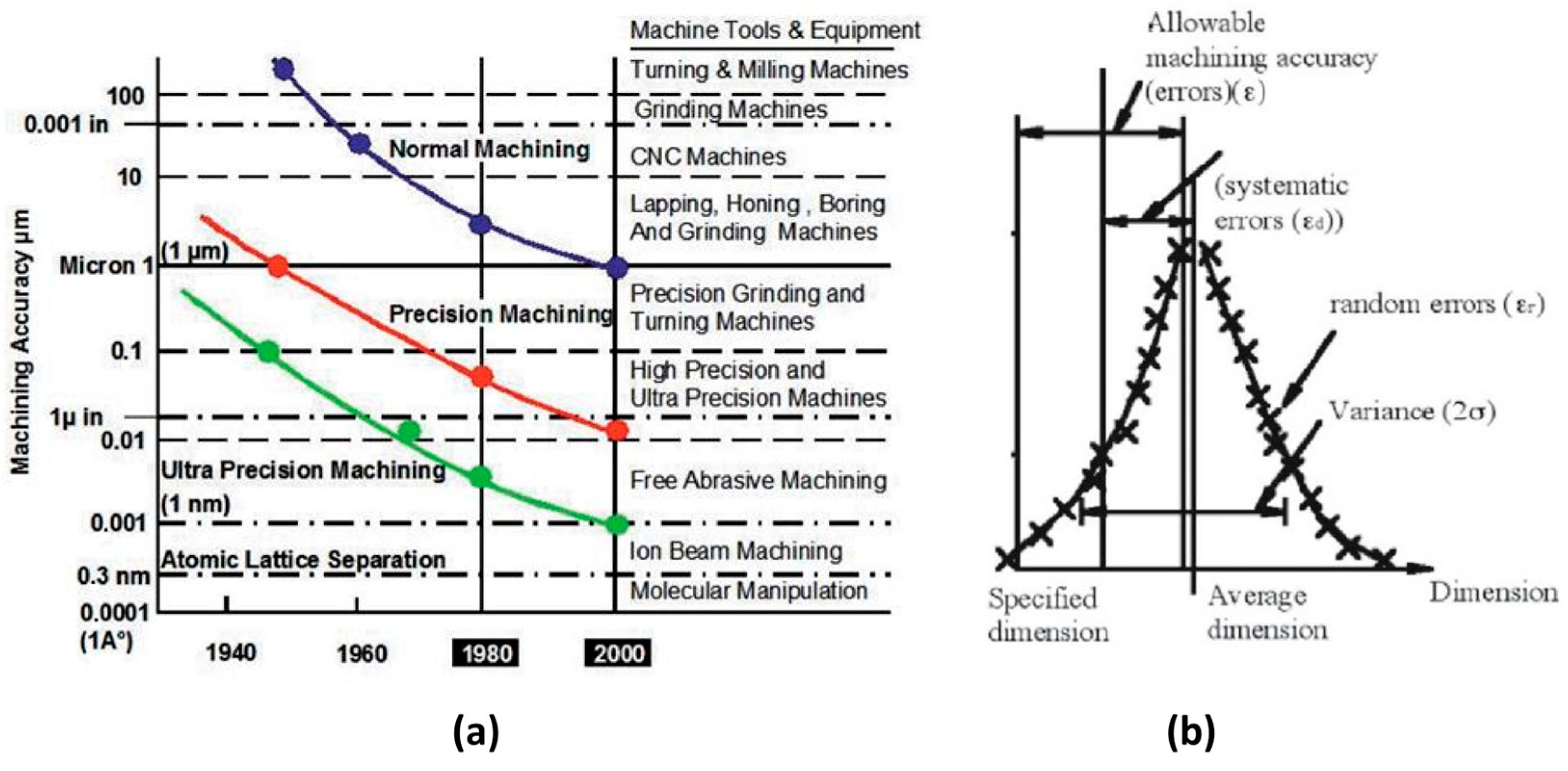
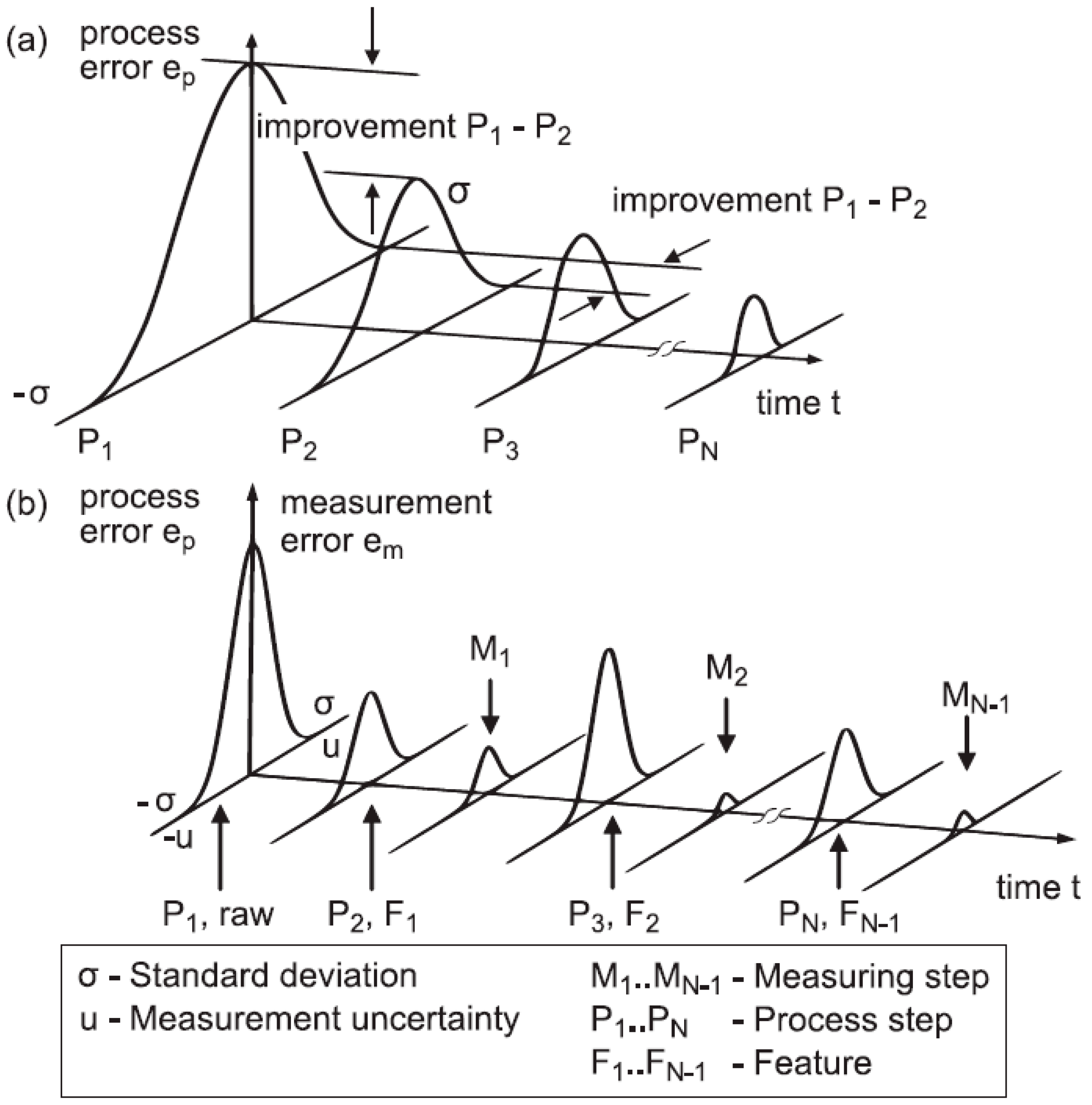
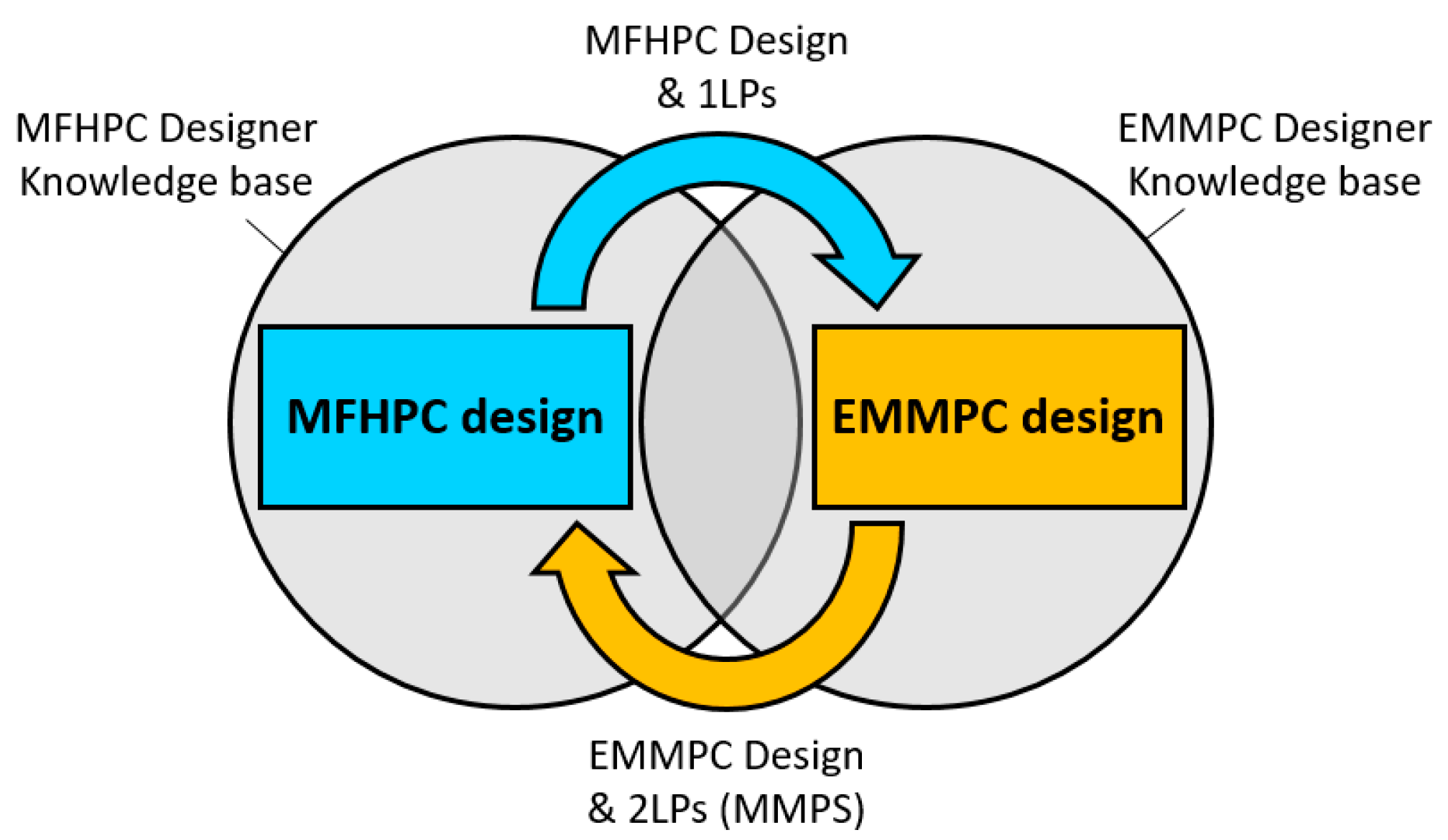
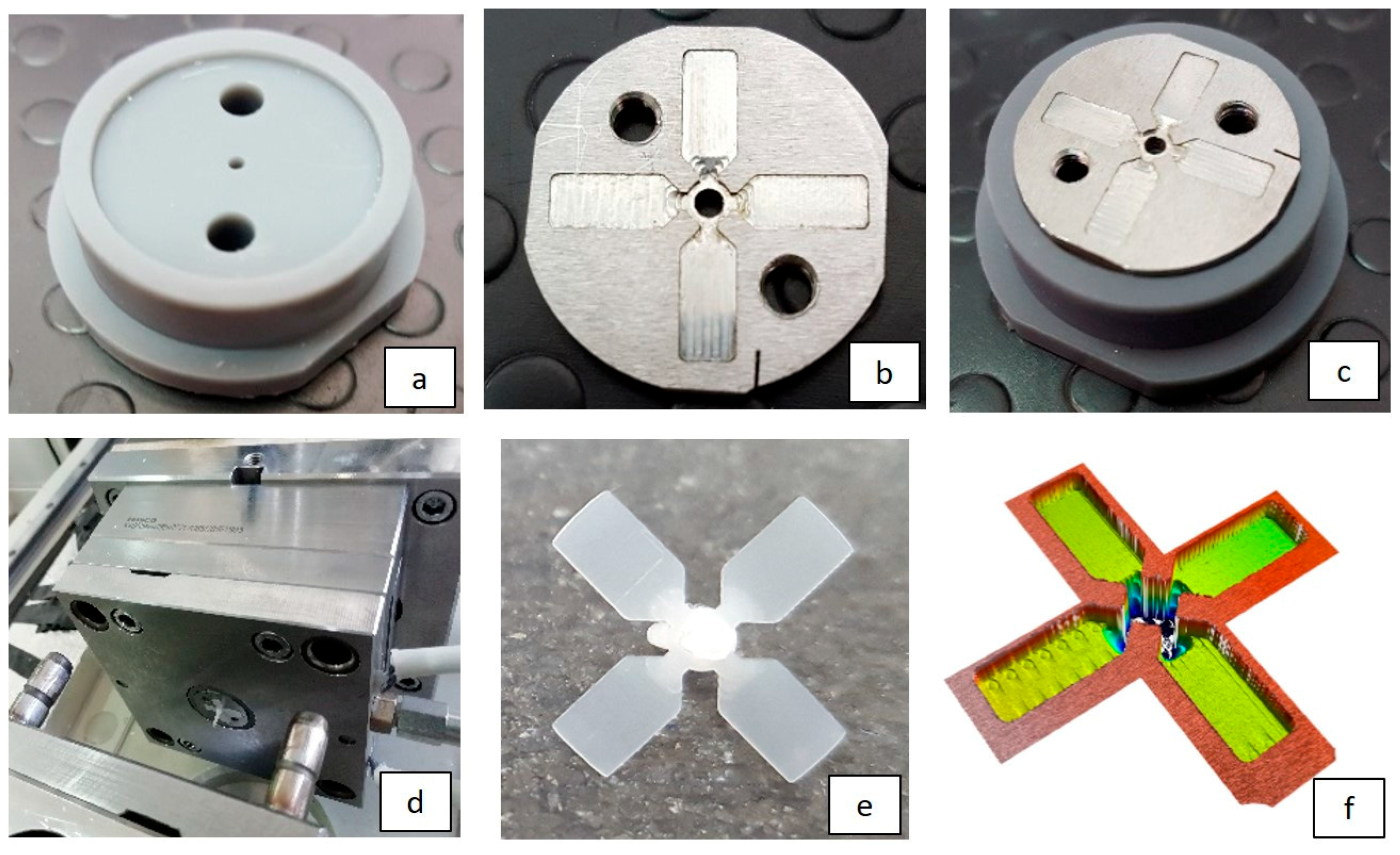
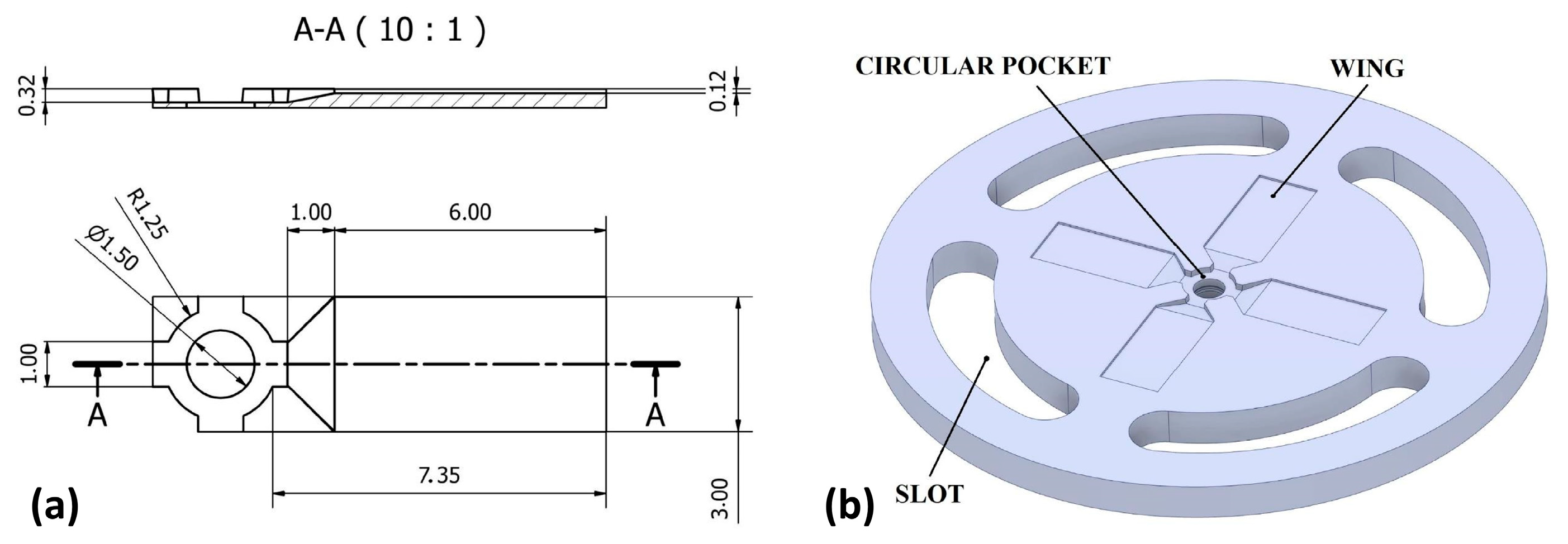
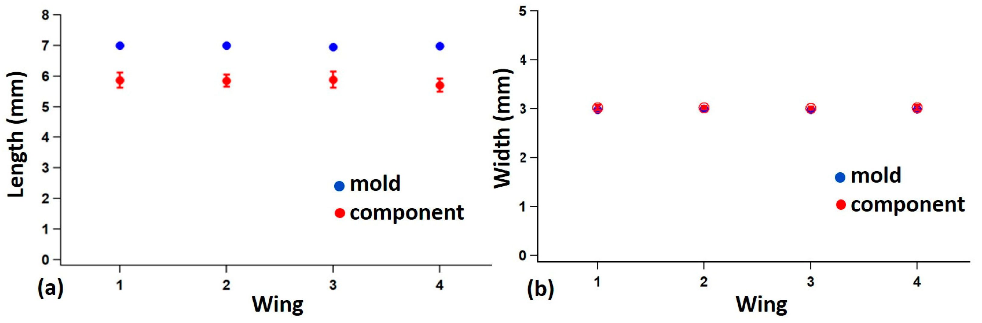
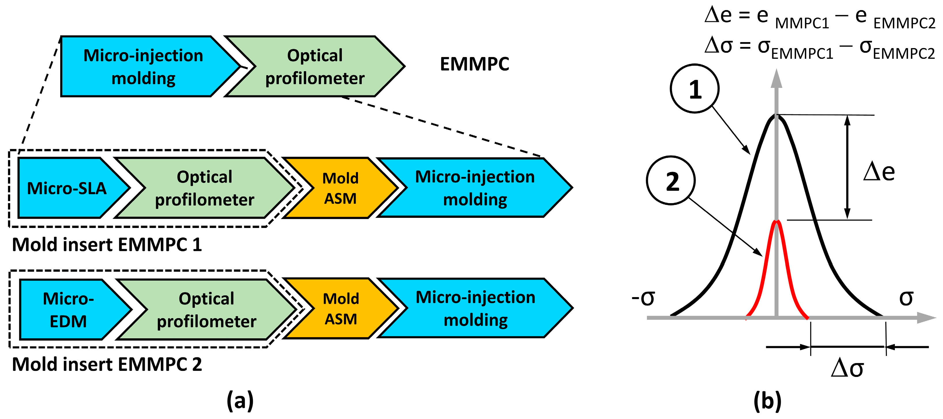
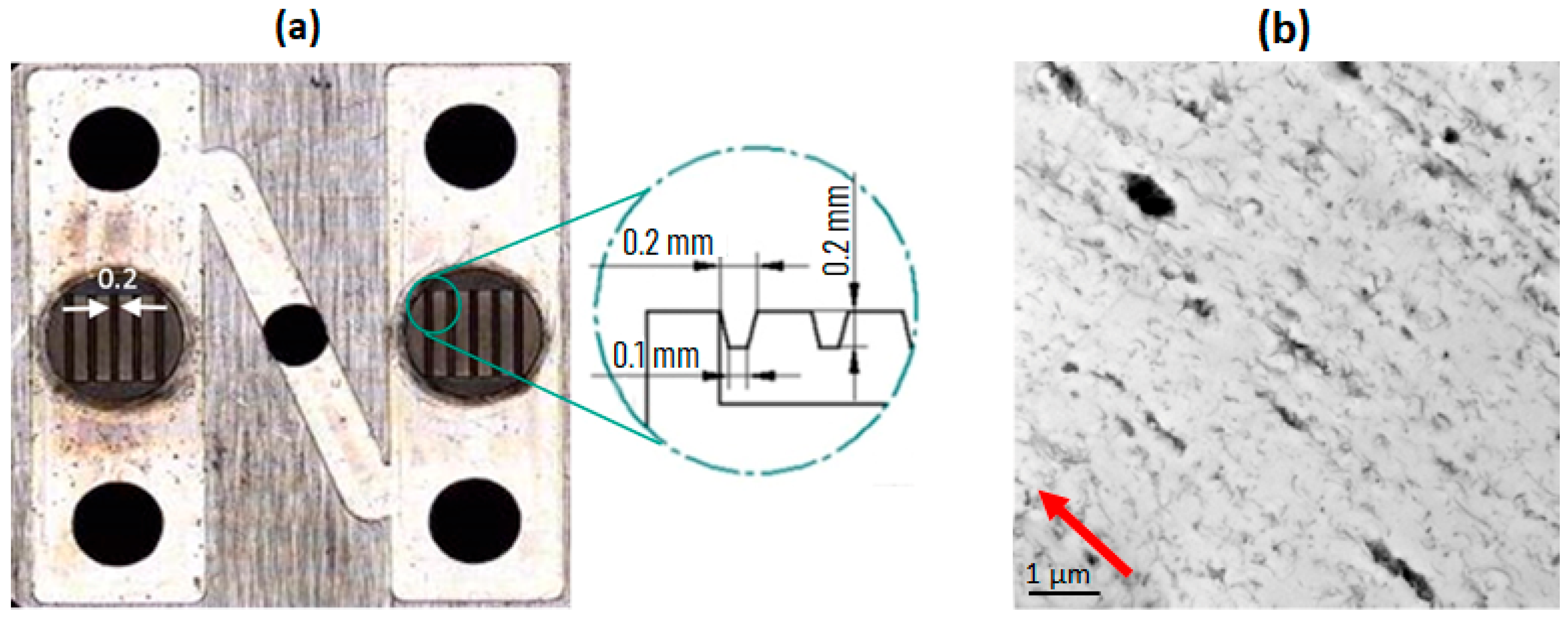
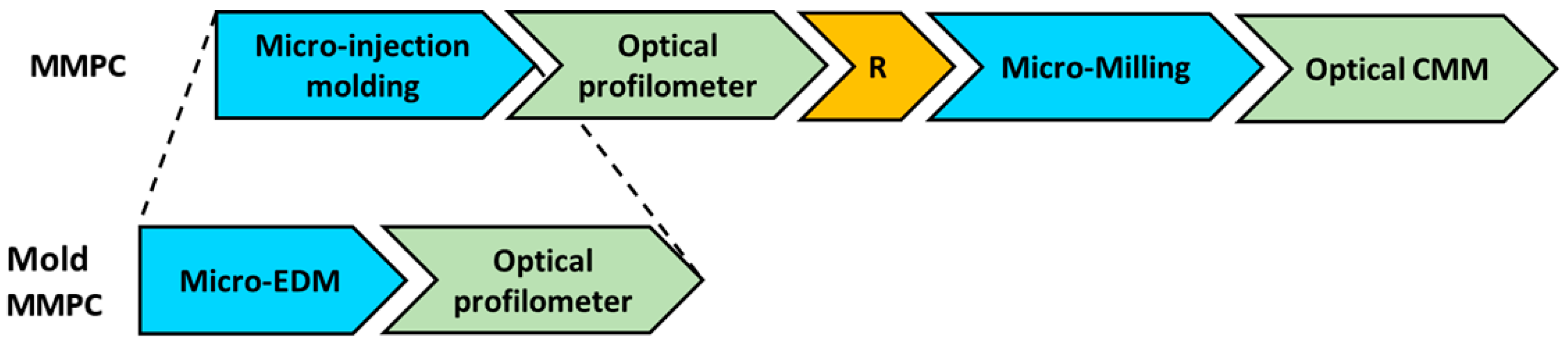
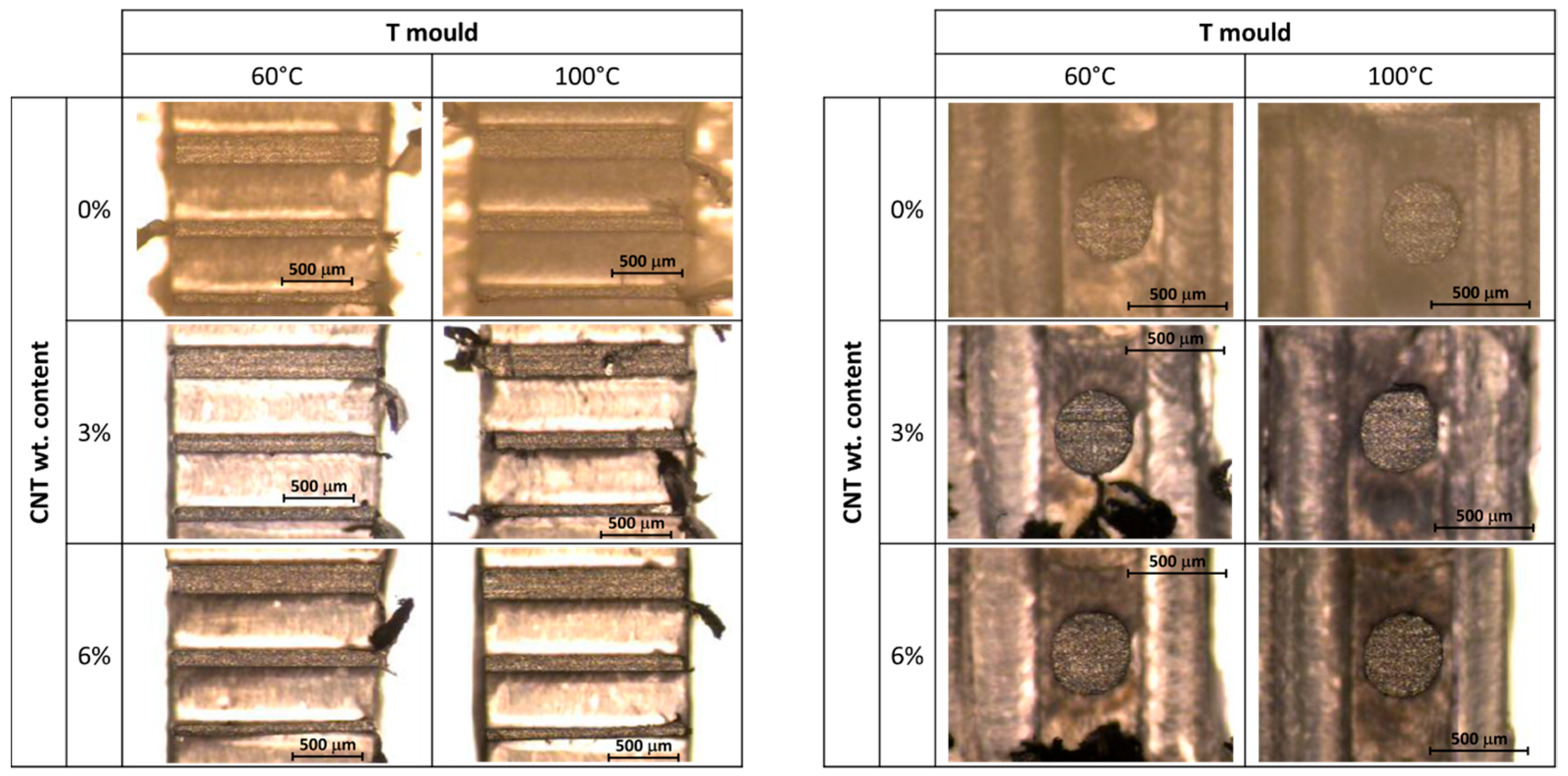
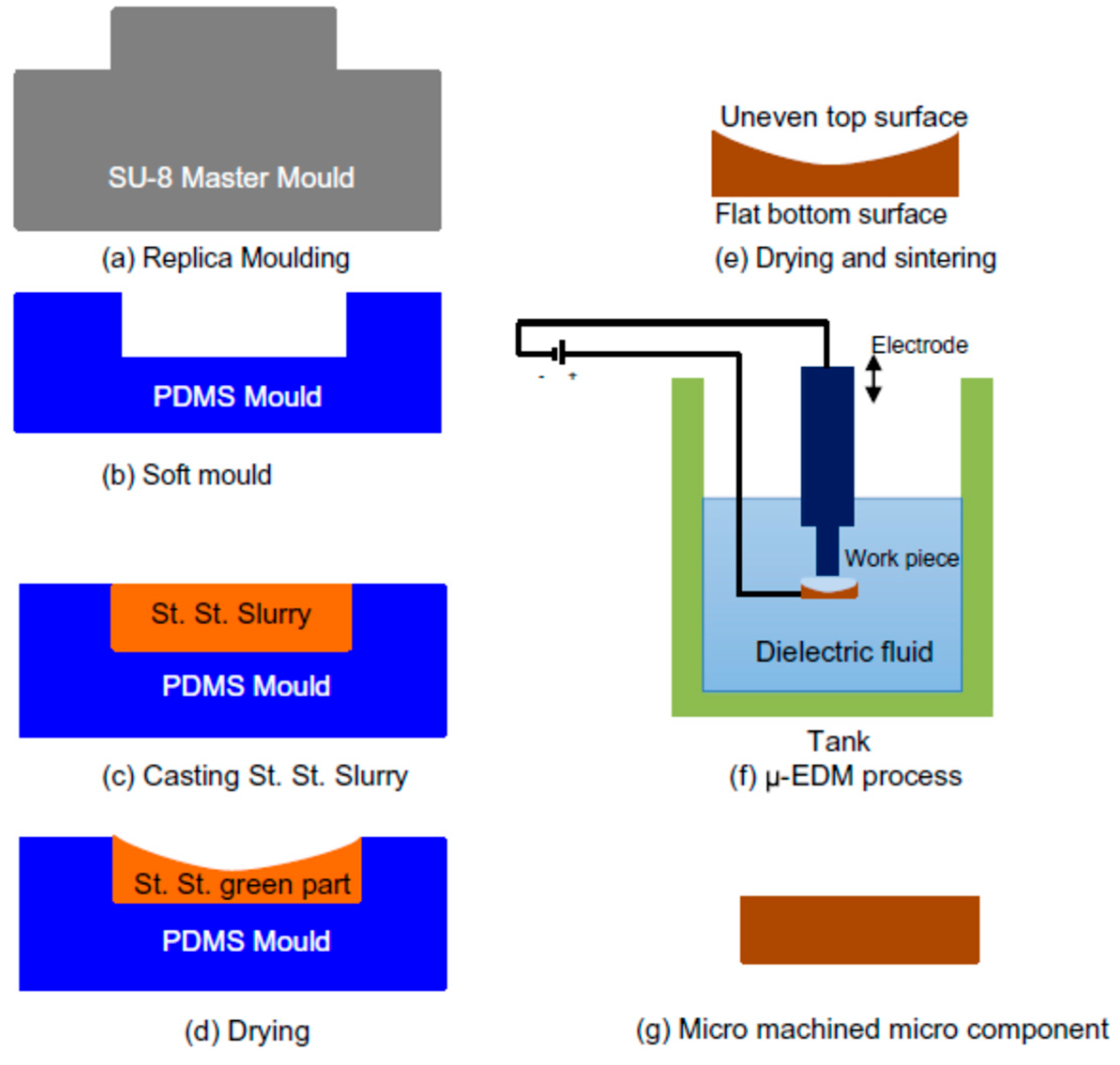
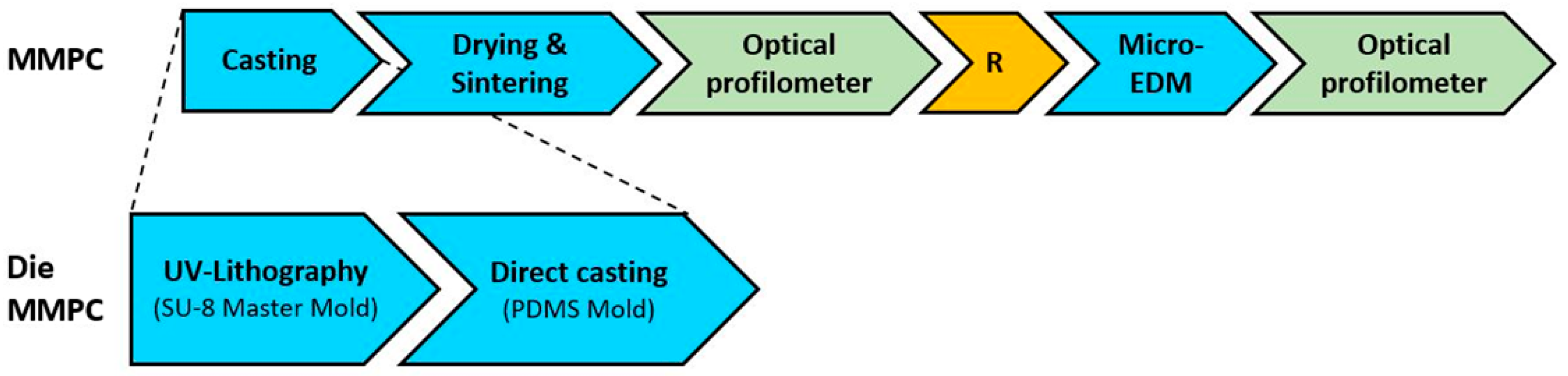
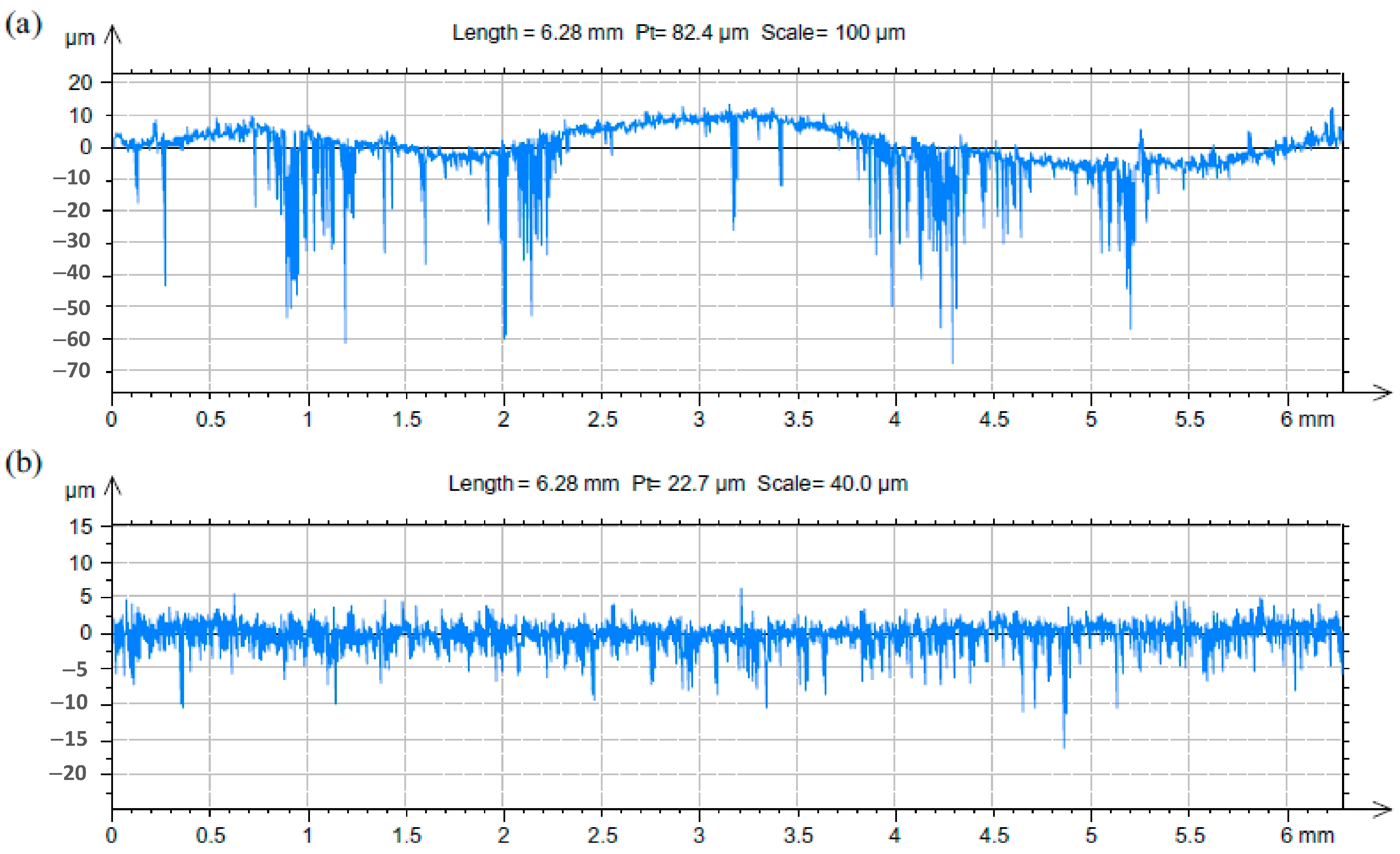
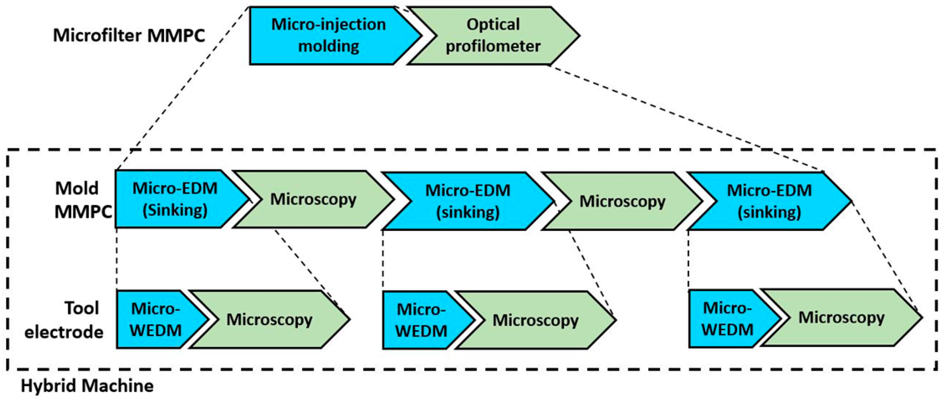
Table 1.
Comparison of performance, machining time, and costs.
| MMPC | Processes | Description | Material Cost (EUR) | Machine Time (h) | Machine Cost (EUR/h) 1 | Operator Time (h) | Total Time (h) | Total Cost (EUR) |
|---|---|---|---|---|---|---|---|---|
| 1 | Turning | Steel mold | Steel: 0.3 | 2 | 10 | 3 | 3 | 140.3 |
| EDM | 6 | 40 | 2 | 6 | 320 | |||
| 2 | SLA | Resin mold | Hard resin: 26 | 12 | 0.8 | 0.5 | 12 | 55.6 |
| 3 | SLA | Resin mold and steel disk | Resin: 20 | 10 | 0.8 | 0.5 | 10 | 48 |
| Milling | Steel: 0.02 | 2 | 25 | 2 | 2 | 130 |
1 Machine costs include also setup, tools, and consumables. The operator costs 40 EUR/h for all processes.
Table 2.
Micro-EDM performance.
| Parameter | Units | HEX-300 | HEX-200 | HEX-CH | HEX-300-150 |
|---|---|---|---|---|---|
| Depth error | (mm) | 0.001 | 0.0006 | 0.0018 | 0.0007 |
| Machining time | (s) | 5965 | 6067 | 5600 | 5697 |
| Average Speed | (mm/s) | 0.62 | 0.62 | 0.60 | 0.63 |
| MRR | (mm3/min) | 0.0086 | 0.0086 | 0.0043 | 0.0045 |
| TWR | - | 0.18 | 0.20 | 1.56 | 1.21 |
Table 3.
Comparison of performance, manufacturing time, and costs.
| MMPC | Processes | Description | Material Cost (EUR) | Machine Time (h) | Machine Cost (EUR/h) 1 | Operator Time (h) | Total Time (h) | Total Cost (EUR) |
|---|---|---|---|---|---|---|---|---|
| 1 | SLA | Resin mold | Hard resin: 26 | 12 | 0.8 | 0.5 | 12.5 | 55.6 |
| 2 | micro-EDM | Steel mold | Steel: 0.3 | 22 | 40 | 2 | 24 | 960.3 |
1 Machine costs include also setup, tools, and consumables. The operator costs 40 EUR/h for all processes.
Table 4.
Dimensional error results.
| Material | Dimensional Error (μm) | |
|---|---|---|
| Thin Wall Thickness | Pillar Diameter | |
| POM composites | min: −1; max: 35 | min: −12; max: 30 |
| LCP composites | min: 40; max: 130 | min: −22; max: 27 |
Table 5.
Micro-channels’ measured widths and depths.
| Channel | Nominal Width | Average Value (Standard Deviation) | Nominal Depth | Average Value (Standard Deviation) | ||||||
|---|---|---|---|---|---|---|---|---|---|---|
| Channel Width @Position x (mm) | Channel Depth @Position x (mm) | |||||||||
| x = 0.3 | x = 0.6 | x = 0.75 | x = 0.9 | x = 0.3 | x = 0.6 | x = 0.75 | x = 0.9 | |||
| # | (μm) | (µm) | (µm) | (µm) | (µm) | (µm) | (µm) | (µm) | (µm) | (µm) |
| A | 70 | 68 (2.6) | - | - | - | 150 | 150 (1.4) | - | - | - |
| B | 71 (1.4) | 71 (1.9) | - | - | 151.7 (2.8) | 153.5 (1.9) | - | - | ||
| C | 70 (1.1) | 70 (1.2) | 68 (1.1) | 63 (1.8) | 152.7 (1.7) | 155.4 (1.2) | 154.1 (2.4) | 150.5 (6.4) | ||
Table 6.
Improvement in the spatial resolution when increasing the sensor pixel resolution (at a constant FoV of 1.876 × 1.407 mm).
Table 6.
Improvement in the spatial resolution when increasing the sensor pixel resolution (at a constant FoV of 1.876 × 1.407 mm).
| Pixel Resolution (pixel) | Spatial Resolution Rs (μm/pixel) | Cost 1 (EUR) |
|---|---|---|
| 640 × 480 | 2.93 | <20 |
| 1280 × 960 | 1.47 | <20 |
| 1600 × 1200 | 1.17 | <20 |
| 2048 × 1536 | 0.92 | 55 |
| 2592 × 1944 | 0.72 | 70 |
1 Reference costs have been estimated by online market (February 2018).
Disclaimer/Publisher’s Note: The statements, opinions and data contained in all publications are solely those of the individual author(s) and contributor(s) and not of MDPI and/or the editor(s). MDPI and/or the editor(s) disclaim responsibility for any injury to people or property resulting from any ideas, methods, instructions or products referred to in the content. |
© 2023 by the authors. Licensee MDPI, Basel, Switzerland. This article is an open access article distributed under the terms and conditions of the Creative Commons Attribution (CC BY) license (https://creativecommons.org/licenses/by/4.0/).
Share and Cite
MDPI and ACS Style
Basile, V.; Modica, F.; Rebaioli, L.; Surace, R.; Fassi, I. Process Chains for Micro-Manufacturing: Modeling and Case Studies. J. Manuf. Mater. Process. 2023, 7, 215. https://doi.org/10.3390/jmmp7060215
AMA Style
Basile V, Modica F, Rebaioli L, Surace R, Fassi I. Process Chains for Micro-Manufacturing: Modeling and Case Studies. Journal of Manufacturing and Materials Processing. 2023; 7(6):215. https://doi.org/10.3390/jmmp7060215
Chicago/Turabian StyleBasile, Vito, Francesco Modica, Lara Rebaioli, Rossella Surace, and Irene Fassi. 2023. "Process Chains for Micro-Manufacturing: Modeling and Case Studies" Journal of Manufacturing and Materials Processing 7, no. 6: 215. https://doi.org/10.3390/jmmp7060215