
In-Process Machining Distortion Prediction Method Based on Bulk Residual Stresses Estimation from Reduced Layer Removal


Abstract
:1. Introduction
2. Materials and Methods
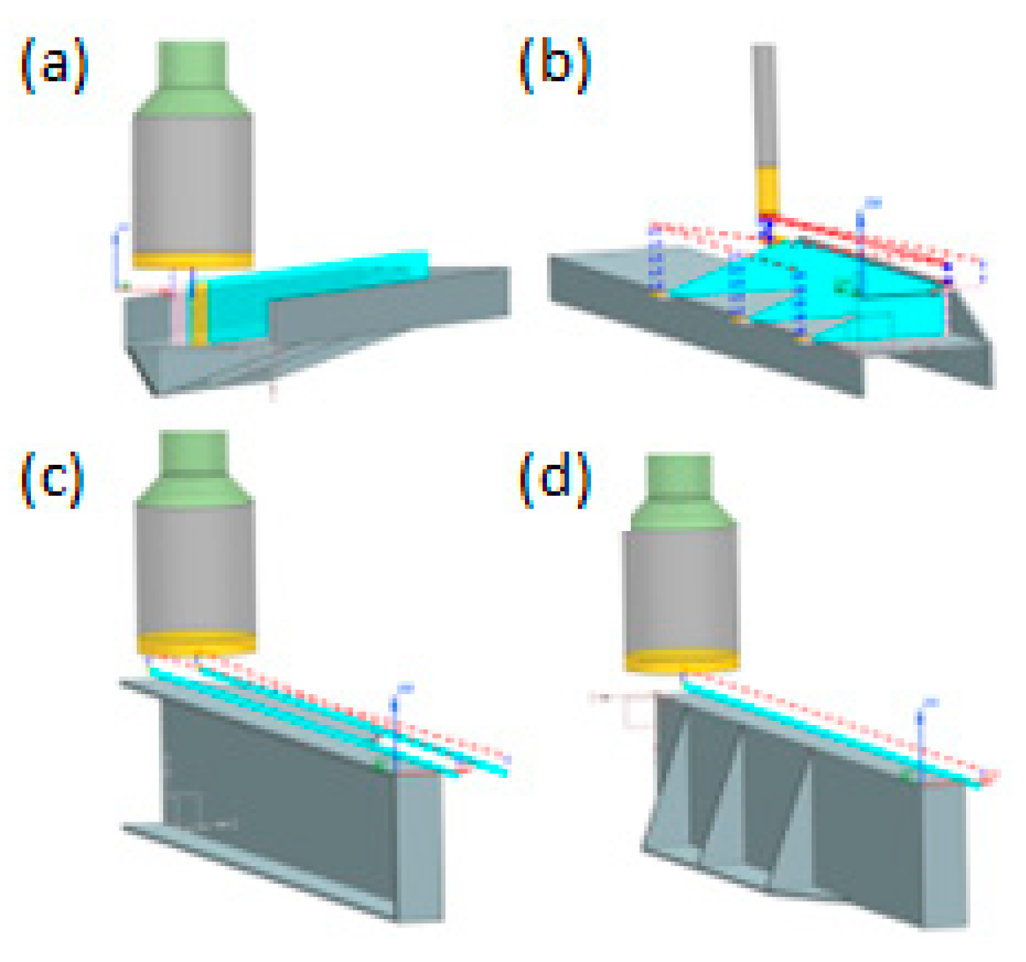
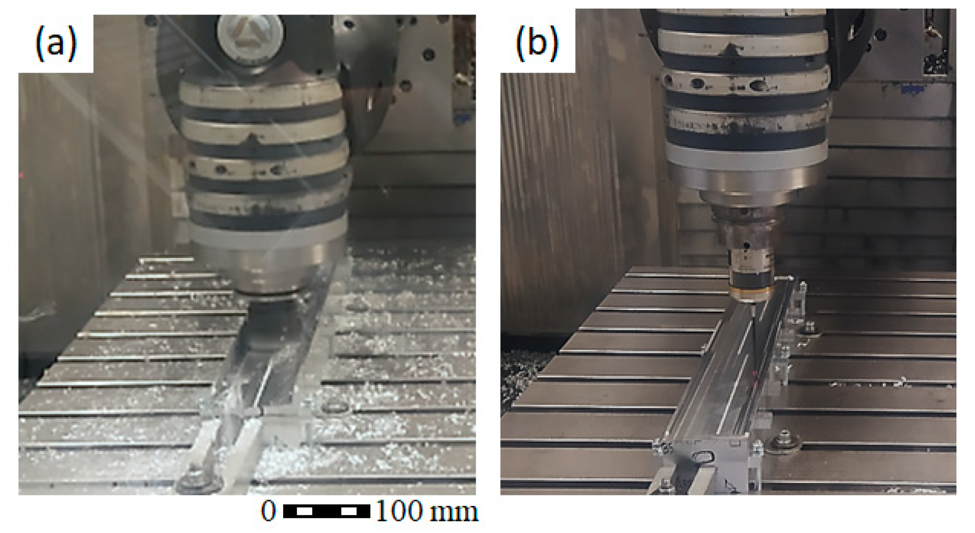
2.1. On-Machine LR in Ribbed Geometries: Semi-Non-Destructive Method
2.2. Reduced LR Measurement and BIRS Estimation
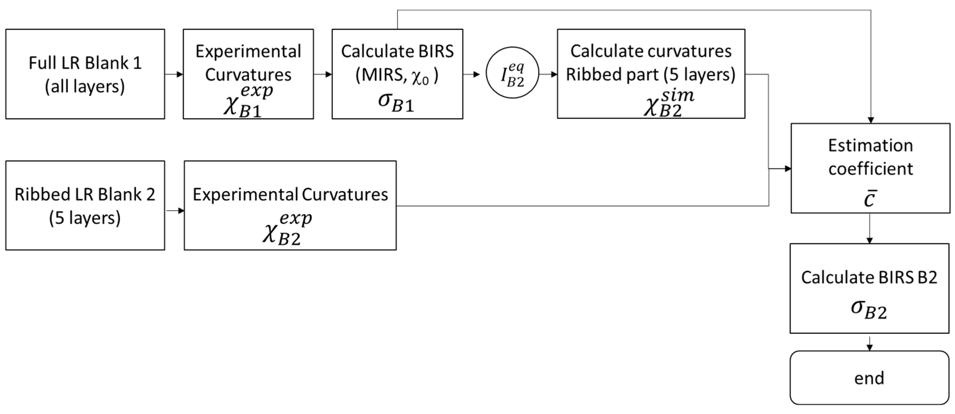
- Perform a BIRS measurement in one blank (B1) by on-machine full LR. In this way, the through-thickness stress profile () of a blank of the same characteristics (material, geometry, supplier, and batch) as the one that will be used for manufacturing the final part (B2) are obtained.
- Plan the machining strategy of the final part, including 5 layers of machining, full roughing, and finishing phases. These layers can be machined with ribs if the final part geometry requires it. As a minimum, an approximate depth of 15% of the height is considered to provide good results in terms of accuracy.
- Perform the ribbed reduced LR of 5 layers in the blank from which the final part will be manufactured (B2) and measure the associated curvatures ).
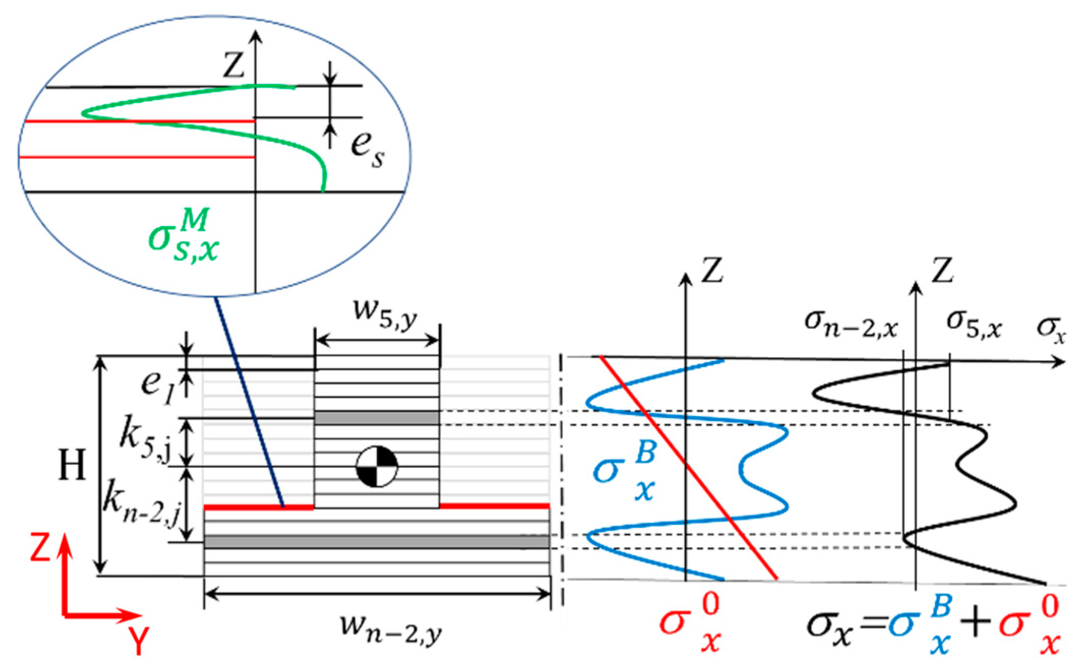
- Calculate the curvatures with the inverse LR formulation, using as input data the BIRS measured in the blank B1 (), the layer discretisation and geometry (ribs layout) of B2, and the equivalent bending stiffness .
- Determine the BIRS estimation coefficient using Equations (1) and (2) (with analogous expressions applying to Y direction), m being the number of LR steps performed, i.e., 5 LR steps, and being the Poisson’s ratio.
- Obtain the estimated BIRS corresponding to blank B2 () using Equation (3).
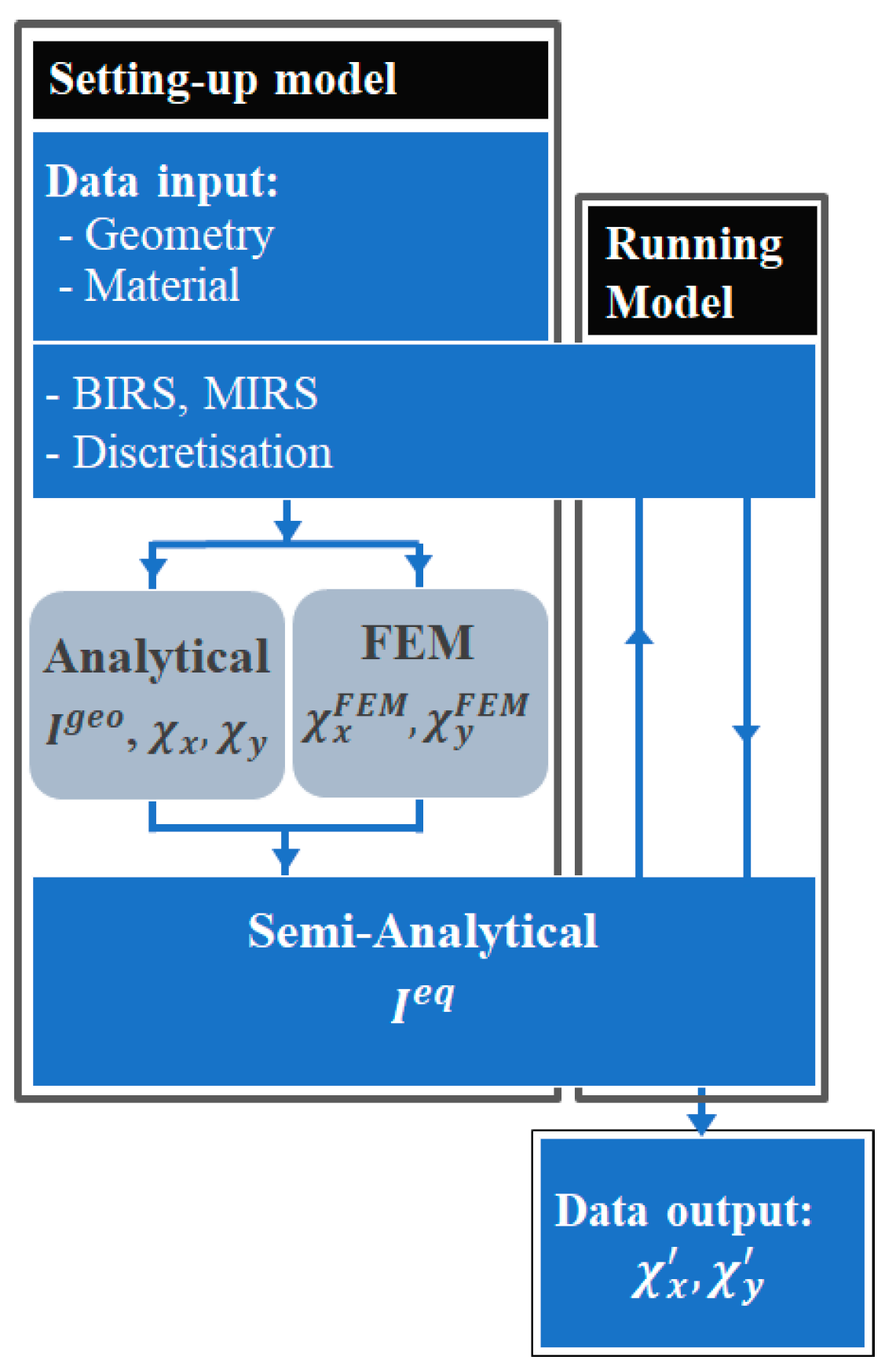
2.3. Distortion Prediction and Uncertainty Assessment
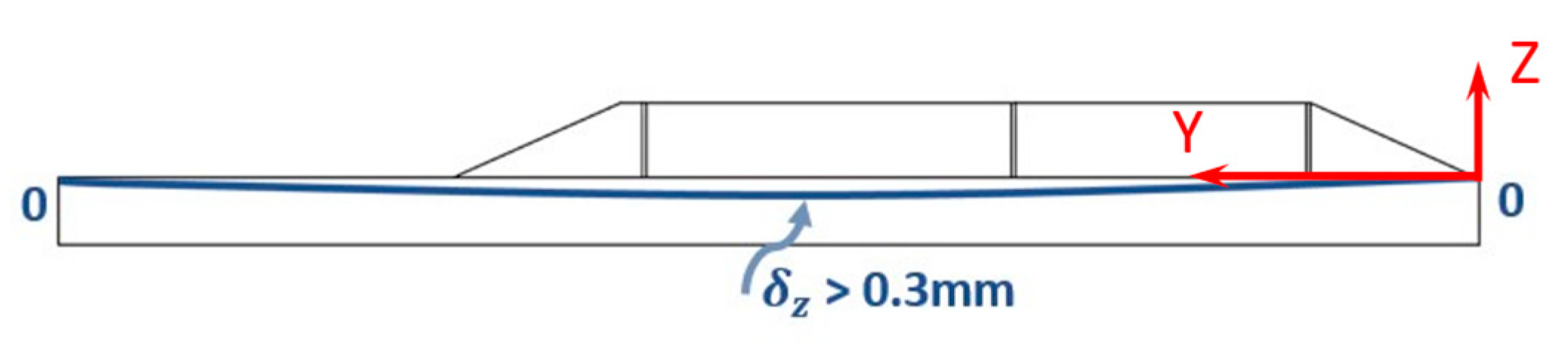
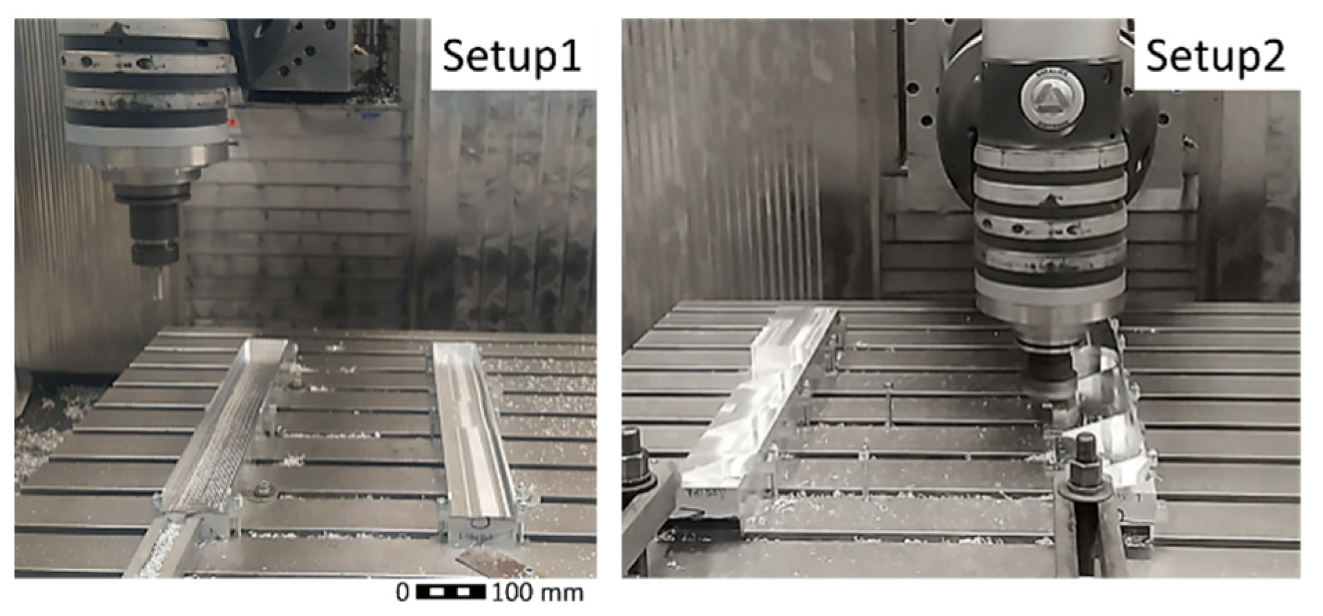
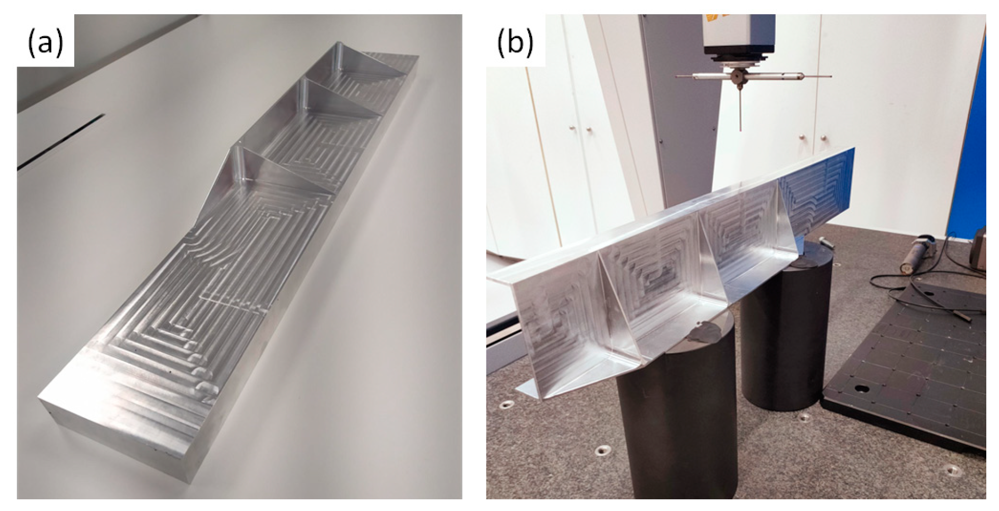
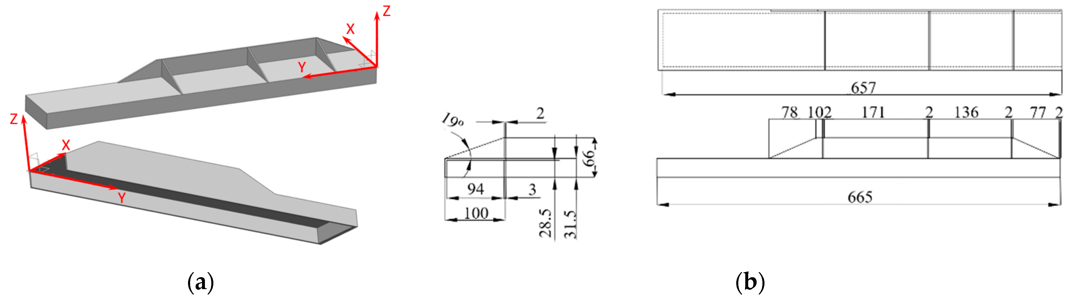
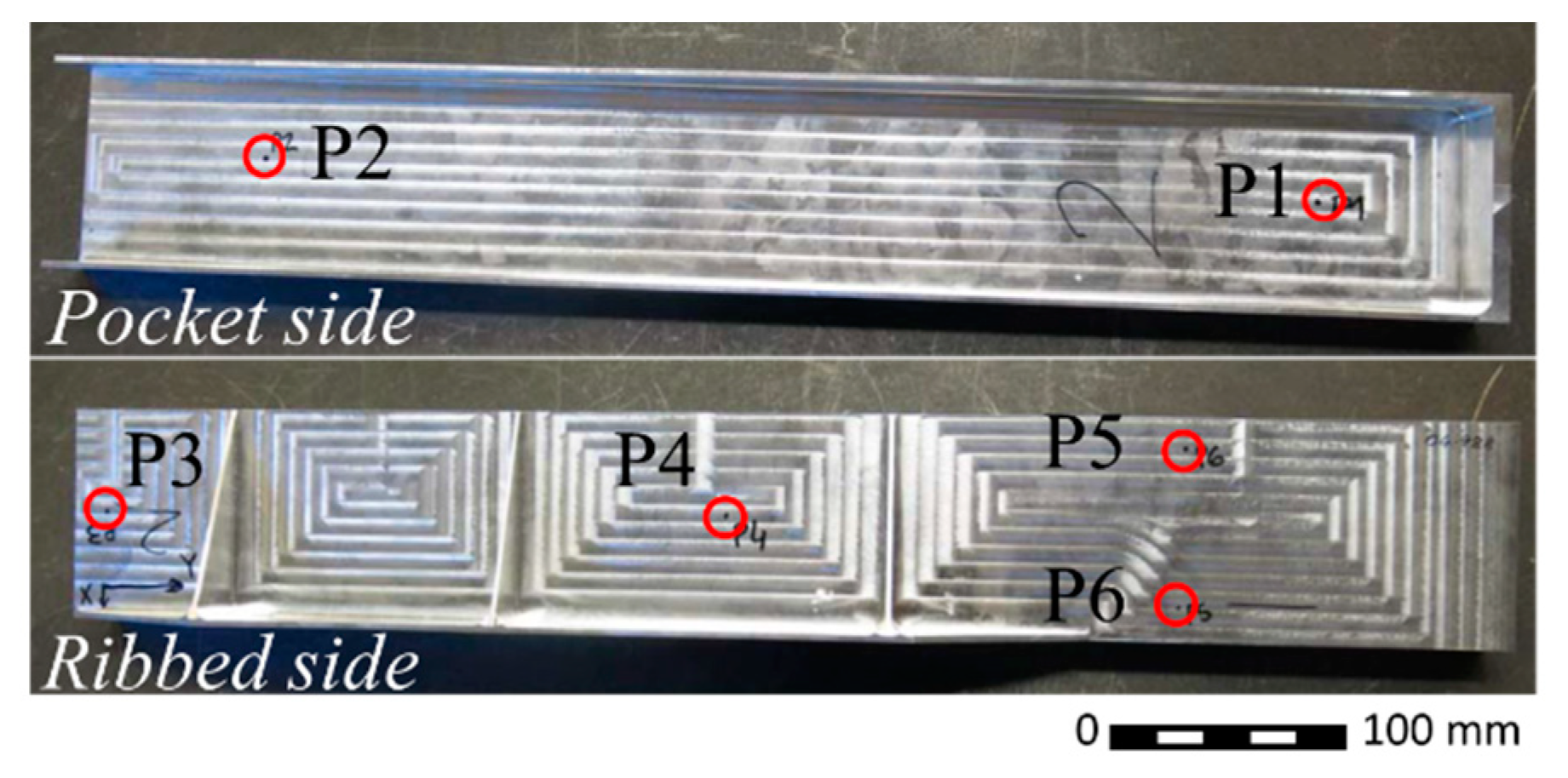
2.4. Test-Case Definition and Experimental Procedure
3. Results
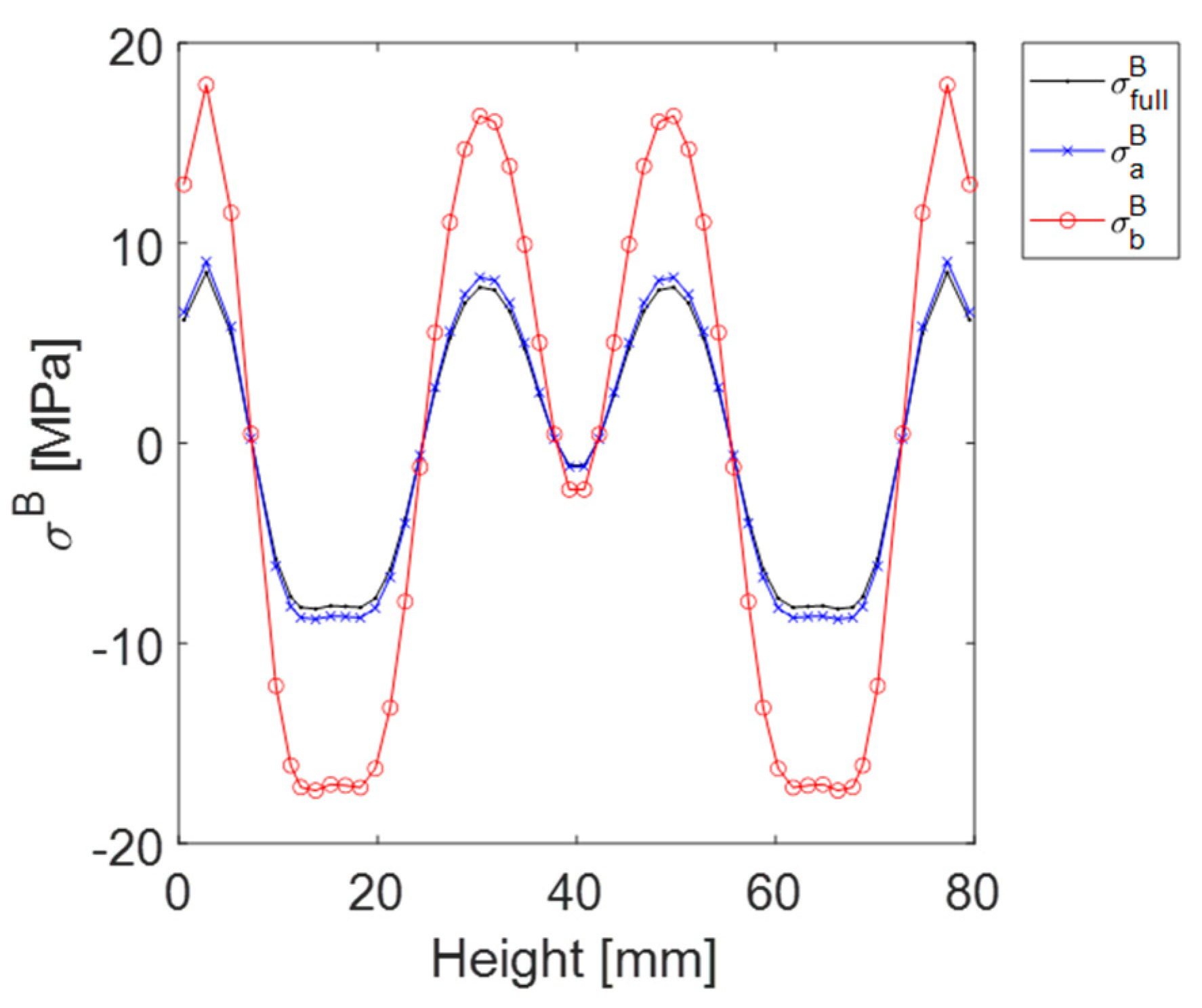
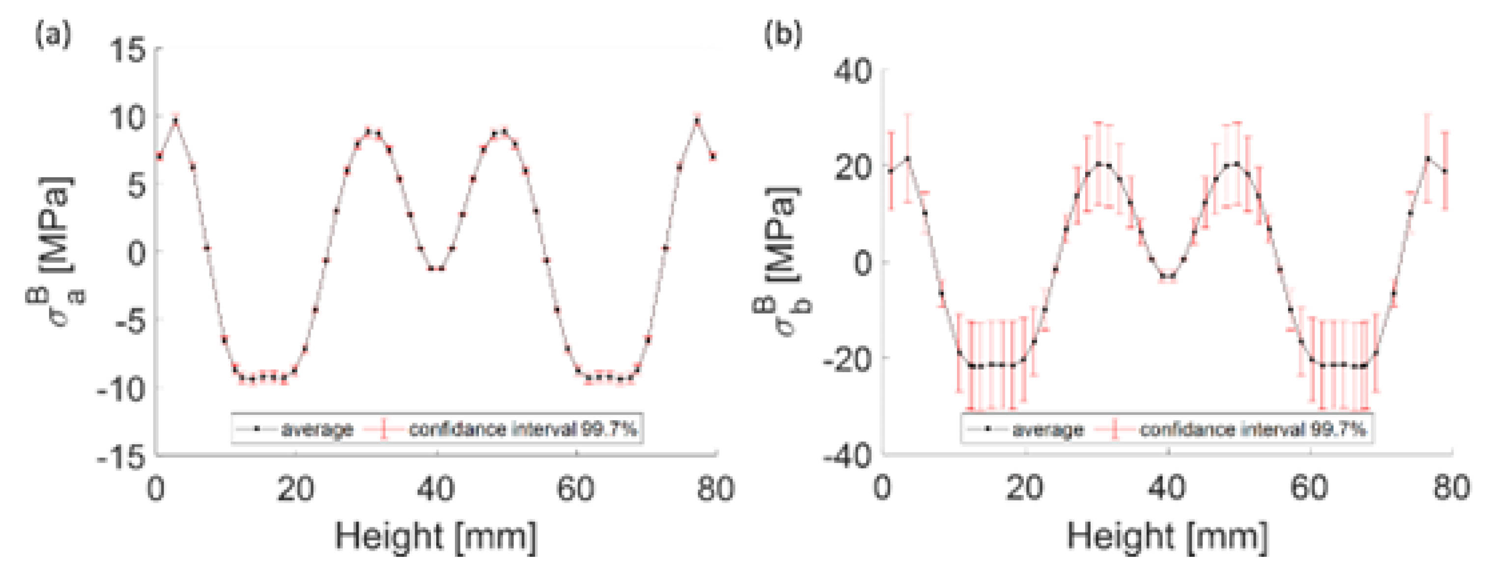
3.1. Input Data for the Distortion Prediction
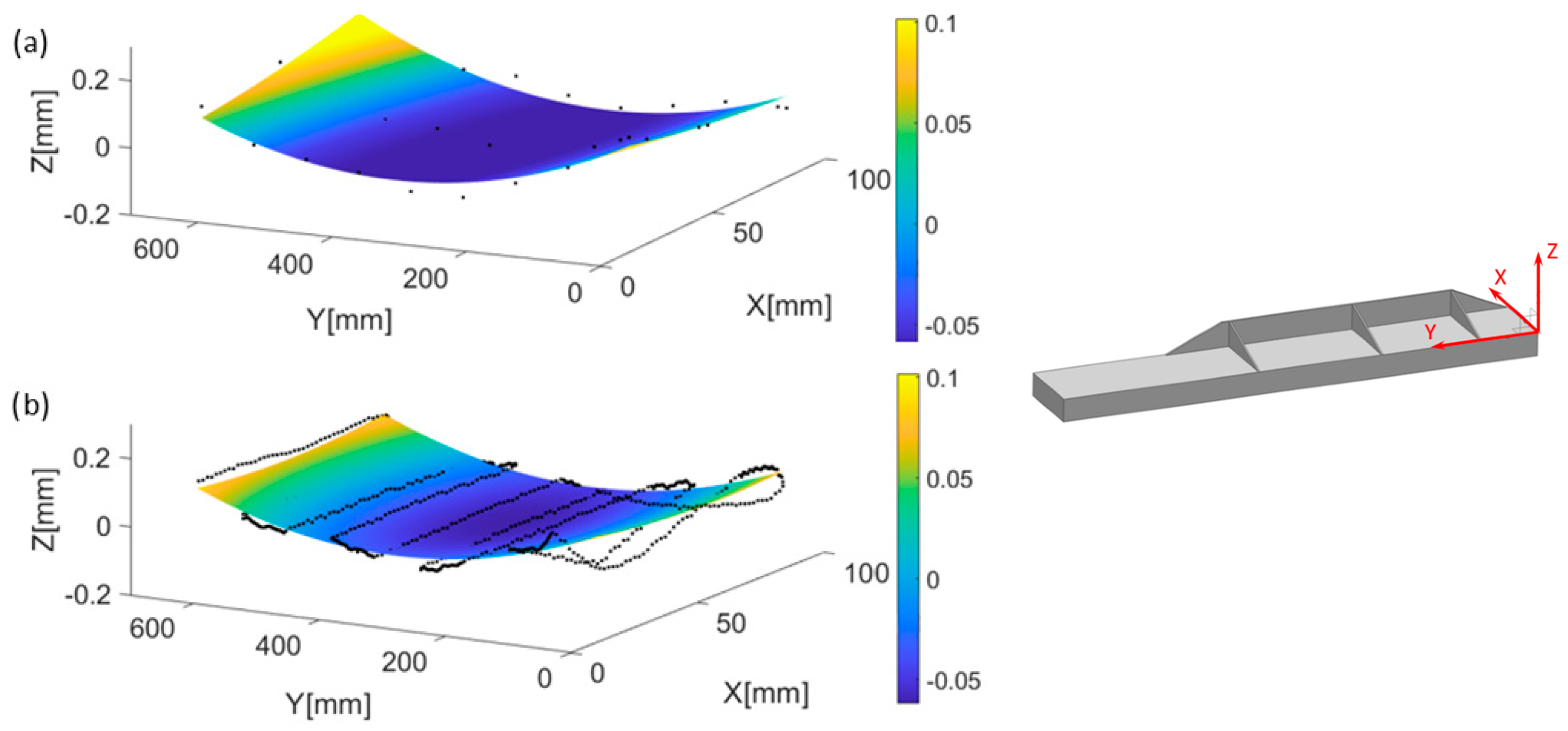
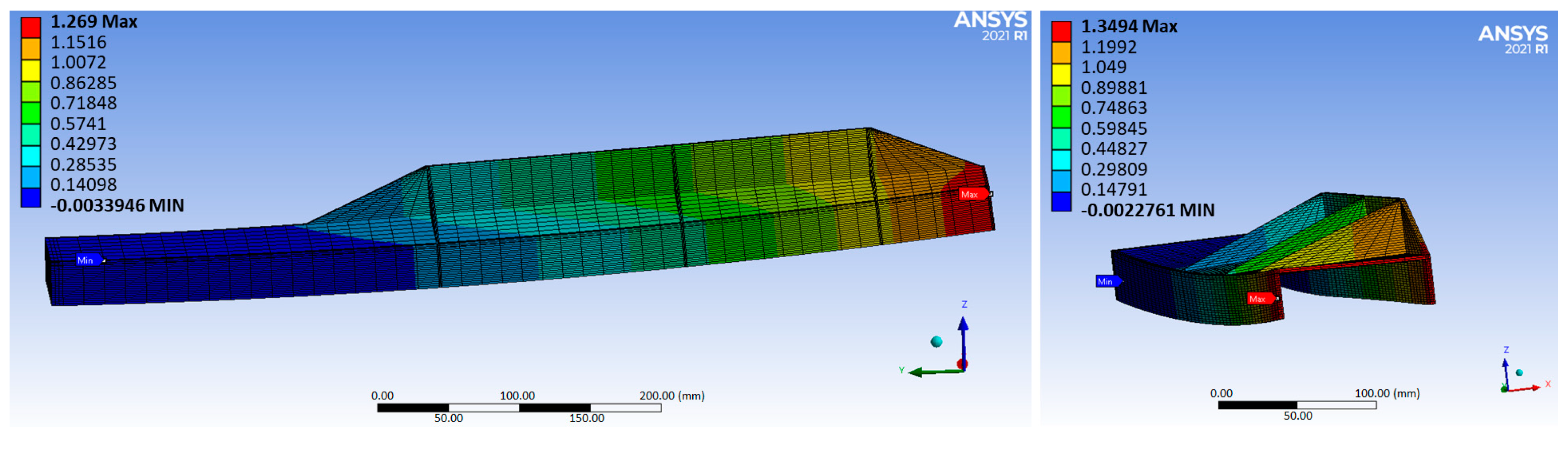
3.2. Distortion and Uncertainty Results
4. Discussion
5. Conclusions
- The hybrid distortion model is an agile and accurate tool for machining distortion calculation, which can be used in different ribbed geometries typical of aerostructures, and enables the performing of distortion analysis at the process planning stage. The model is validated experimentally in aluminium test parts, showing a prediction accuracy, in comparison to experimental results, below 10%, within the uncertainty range calculated. This uncertainty range is linked to the BIRS measurement uncertainty (probing uncertainty of on-machine LR).
- Considering that performing a complete BIRS measurement is not industrially feasible, the reduced LR and BIRS estimation offers the possibility of obtaining the actual BIRS of the blanks in a cost-effective way, and calculating the machining distortion of final parts, as well as their uncertainty ranges. The experimental results in aluminium aerostructures demonstrate the validity of the approach, which provides an alternative to confronting distortion in production lines.
- Due to the uncertainty of bulk residual stress measurements, which are the input of the hybrid distortion model, providing a distortion prediction uncertainty range is as important as the prediction itself. In fact, the part geometry and its bending stiffness are factors from which it can be foreseen whether the distortion prediction procedure introduced here is valid or not.
Author Contributions
Funding
Data Availability Statement
Conflicts of Interest
References
- Bowden, D.M.; Halley, J.E. Aluminium Reliability Improvement Program Final Report 60606; The Boeing Company: Chicago, IL, USA, 2001. [Google Scholar]
- Zoch, H.-W. From Single Production Step to Entire Process Chain—The Global Approach of Distortion Engineering. Mater. Werkst. 2006, 37, 6–10. [Google Scholar] [CrossRef]
- Ma, K.; Goetz, R.; Srivatsa, S.K. Modeling of Residual Stress and Machining Distortion in Aerospace Components. ASM Handb. 2010, 22B, 386–407. [Google Scholar] [CrossRef]
- Gao, H.; Zhang, Y.; Wu, Q.; Song, J. An analytical model for predicting the machining deformation of a plate blank considers biaxial initial residual stresses. Int. J. Adv. Manuf. Technol. 2017, 93, 1473–1486. [Google Scholar] [CrossRef]
- Li, B.; Deng, H.; Hui, D.; Hu, Z.; Zhang, W. A semi-analytical model for predicting the machining deformation of thin-walled parts considering machining-induced and blank initial residual stress. Int. J. Adv. Manuf. Technol. 2020, 110, 139–161. [Google Scholar] [CrossRef]
- Akhtar, W.; Lazoglu, I.; Liang, S.Y. Prediction and control of residual stress-based distortions in the machining of aerospace parts: A review. J. Manuf. Process 2022, 76, 106–122. [Google Scholar] [CrossRef]
- Mathews, R.; Sunny, S.; Malik, A.; Halley, J. Coupling between inherent and machining-induced residual stresses in aluminum components. Int. J. Mech. Sci. 2022, 213, 106865. [Google Scholar] [CrossRef]
- Brinksmeier, E.; Cammett, J.T.; König, W.; Leskovar, P.; Peters, J.; Tönshoff, H.K. Residual Stresses—Measurement and Causes in Machining Processes. CIRP Ann. 1982, 31, 491–510. [Google Scholar] [CrossRef]
- Yang, Y.; Li, M.; Li, K.R. Comparison and analysis of main effect elements of machining distortion for aluminum alloy and titanium alloy aircraft monolithic component. Int. J. Adv. Manuf. Technol. 2014, 70, 1803–1811. [Google Scholar] [CrossRef]
- Li, J.; Wang, S. Distortion caused by residual stresses in machining aeronautical aluminum alloy parts: Recent advances. Int. J. Adv. Manuf. Technol. 2017, 89, 997–1012. [Google Scholar] [CrossRef]
- Weber, D. Investigation on the scale effects of initial bulk and machining induced residual stresses of thin walled milled monolithic aluminum workpieces on part distortions: Experiments and finite element prediction model. Procedia CIRP 2021, 102, 337–342. [Google Scholar] [CrossRef]
- Bates, C.E. Selecting quenchants to maximize tensile properties and minimize distortion in aluminum parts. J. Heat. Treat. 1987, 5, 27–40. [Google Scholar] [CrossRef]
- Prime, M.B.; Hill, M.R. Residual stress, stress relief, and inhomogeneity in aluminum plate. Scr. Mater. 2002, 46, 77–82. [Google Scholar] [CrossRef]
- Robinson, J.S.; Tanner, D.A.; Truman, C.E. 50th Anniversary Article: The Origin and Management of Residual Stress in Heat-treatable Aluminium Alloys. Strain 2014, 50, 185–207. [Google Scholar] [CrossRef]
- Sim, W.M. Challenges of residual stress and part distortion in the civil airframe industry. Int. J. Microstruct. Mater. Prop. 2010, 5, 446. [Google Scholar] [CrossRef]
- Barcenas, L.; Ledesma-Orozco, E.; Van-der-Veen, S.; Reveles-Arredondo, F.; Rodríguez-Sánchez, E.A. An optimization of part distortion for a structural aircraft wing rib: An industrial workflow approach. CIRP J. Manuf. Sci. Technol. 2020, 28, 15–23. [Google Scholar] [CrossRef]
- Wang, Z.; Sun, J.; Liu, L.; Wang, R.; Chen, W. An analytical model to predict the machining deformation of frame parts caused by residual stress. J. Mater. Process Technol. 2019, 274, 116282. [Google Scholar] [CrossRef]
- Carlisle, O.J. Modelling the Effects of Residual Stress and Material Removal in Sheet Metal Forming. Ph.D. Thesis, University of Ulster, Coleraine, UK, 2012. [Google Scholar]
- Jiang, Z.; Liu, Y.; Li, L.; Shao, W. A novel prediction model for thin plate deflections considering milling residual stresses. Int. J. Adv. Manuf. Technol. 2014, 74, 37–45. [Google Scholar] [CrossRef]
- Fan, L.; Tian, H.; Li, L.; Yang, Y.; Zhou, N.; He, N. Machining Distortion Minimization of Monolithic Aircraft Parts Based on the Energy Principle. Metals 2020, 10, 1586. [Google Scholar] [CrossRef]
- Andersch, C.; Ehlers, M.; Hoffmann, F.; Zoch, H.-W. Systematic analysis of the correlation between part geometry and distortion due to heat treatment. Mater. Werkst. 2006, 37, 23–28. [Google Scholar] [CrossRef]
- Yang, Y.; Li, X.; Li, L.; He, N.; Zhao, G.; Chen, N.; Lan, H.; Zhou, Z. Investigation on deformation of single-sided stringer parts based on fluctuant initial residual stress. J. Mater. Process Technol. 2019, 271, 623–633. [Google Scholar] [CrossRef]
- Schajer, G.S. (Ed.) Practical Residual Stress Measurement Methods; Wiley: Chichester, UK, 2013. [Google Scholar]
- Guo, J.; Fu, H.; Pan, B.; Kang, R. Recent progress of residual stress measurement methods: A review. Chin. J. Aeronaut. 2019, 34, 54–78. [Google Scholar] [CrossRef]
- Aurrekoetxea, M.; Llanos, I.; Zelaieta, O.; Lopez de Lacalle, L.N. Improving accuracy of bulk residual stress characterization in ribbed geometries through equivalent bending stiffness. Procedia CIRP 2021, 102, 325–330. [Google Scholar] [CrossRef]
- Aurrekoetxea, M.; Llanos, I.; Zelaieta, O.; Lopez de Lacalle, L.N. Towards advanced prediction and control of machining distortion: A comprehensive review. Int. J. Adv. Manuf. Technol. 2022, 122, 2823–2848. [Google Scholar] [CrossRef]
- Timoshenko, J.N.G. Theory of Plates and Shells; McGraw-Hill Book Company, Incorporated: New York, NY, USA; London, UK, 1940. [Google Scholar]
- Dreier, S.; Denkena, B. Determination of Residual Stresses in Plate Material by Layer Removal with Machine-integrated Measurement. Procedia CIRP 2014, 24, 103–107. [Google Scholar] [CrossRef]
- Aurrekoetxea, M.; López de Lacalle, L.N.; Llanos, I. Machining Stresses and Initial Geometry on Bulk Residual Stresses Characterization by On-Machine Layer Removal. Materials 2020, 13, 1445. [Google Scholar] [CrossRef] [PubMed]
- Aurrekoetxea, M.; Lopez de Lacalle, L.N.; Zelaieta, O.; Llanos, I. Uncertainty assessment for bulk residual stress characterization using Layer Removal method. Exp. Mech. 2023, 63, 323–335. [Google Scholar] [CrossRef]
- ANSYS@ Mechanical User’s Guide; ANSYS Inc.: Cannon Sburg, PA, USA, 2021.
- Madariaga, A.; Perez, I.; Arrazola, P.J.; Sanchez, R.; Ruiz, J.J.; Rubio, F.J. Reduction of distortions in large aluminium parts by controlling machining-induced residual stresses. Int. J. Adv. Manuf. Technol. 2018, 97, 967–978. [Google Scholar] [CrossRef]
- ASTM E837-20; Standard Test Method for Determining Residual Stresses by the Hole-Drilling Strain-Gage Method, Standard Test Method E837-08. American Society for Testing and Materials: West Conshohocken, PA, USA, 2008.
- Grant, P.V.; Lord, J.D.; Whitehead, P.S. The Measurement of Residual Stresses by the Incremental Hole Drilling Technique; National Physical Laboratory: Middlesex, UK, 2002. [Google Scholar]
- Chighizola, C.R.; D’Elia, C.R.; Weber, D.; Kirsch, B.; Aurich, J.C.; Linke, B.S.; Hill, M.R. Intermethod Comparison and Evaluation of Measured Near Surface Residual Stress in Milled Aluminum. Exp. Mech. 2021, 61, 1309–1322. [Google Scholar] [CrossRef]


| Material | Density (g/dm3) | Hardness (HRb) | Young Modulus (GPa) | Poisson’s Ratio (-) |
|---|---|---|---|---|
| Al7175-T7351 | 2.8 | 135 | 71.7 | 0.33 |
| Parameter | D80 mm | D16 mm |
|---|---|---|
| Spindle speed—n (rpm) | 1800 | 4000 |
| Part | (mm) | (mm) | Error (mm) | Error % | Uncertainty (mm) | Uncertainty % |
|---|---|---|---|---|---|---|
| a | 0.255 | 0.273 | 0.018 | 7 | 0.018 | 7 |
| b | 0.262 | 0.270 | 0.008 | 3 | 0.175 | 67 |
Disclaimer/Publisher’s Note: The statements, opinions and data contained in all publications are solely those of the individual author(s) and contributor(s) and not of MDPI and/or the editor(s). MDPI and/or the editor(s) disclaim responsibility for any injury to people or property resulting from any ideas, methods, instructions or products referred to in the content. |
© 2024 by the authors. Licensee MDPI, Basel, Switzerland. This article is an open access article distributed under the terms and conditions of the Creative Commons Attribution (CC BY) license (https://creativecommons.org/licenses/by/4.0/).
Share and Cite
Aurrekoetxea, M.; López de Lacalle, L.N.; Zelaieta, O.; Llanos, I. In-Process Machining Distortion Prediction Method Based on Bulk Residual Stresses Estimation from Reduced Layer Removal. J. Manuf. Mater. Process. 2024, 8, 9. https://doi.org/10.3390/jmmp8010009
Aurrekoetxea M, López de Lacalle LN, Zelaieta O, Llanos I. In-Process Machining Distortion Prediction Method Based on Bulk Residual Stresses Estimation from Reduced Layer Removal. Journal of Manufacturing and Materials Processing. 2024; 8(1):9. https://doi.org/10.3390/jmmp8010009
Chicago/Turabian StyleAurrekoetxea, Maria, Luis Norberto López de Lacalle, Oier Zelaieta, and Iñigo Llanos. 2024. "In-Process Machining Distortion Prediction Method Based on Bulk Residual Stresses Estimation from Reduced Layer Removal" Journal of Manufacturing and Materials Processing 8, no. 1: 9. https://doi.org/10.3390/jmmp8010009