Article

Telemetry System to Monitor Elastic Torque on Rolling Stand Spindles

by
Stanislav S. Voronin
1,
Boris M. Loginov
2,
Olga A. Gasiyarova
3,*,
Sergey A. Evdokimov
4,
Alexander S. Karandaev
4 and
Vadim R. Khramshin
4
1
Department of Automation and Control, Moscow Polytechnic University, 38, Bolshaya Semyonovskaya Str., 107023 Moscow, Russia
2
Central Electrotechnical Laboratory, PJSC Magnitogorsk Iron and Steel Works, 455000 Magnitogorsk, Russia
3
RTC “InTech” LLC, 10, 1-ya Maschinostroeniya Str., 115088 Moscow, Russia
4
Power Engineering and Automated Systems Institute, Nosov Magnitogorsk State Technical University, 38, Lenin Avenue, 455000 Magnitogorsk, Russia
*
Author to whom correspondence should be addressed.
J. Manuf. Mater. Process. 2024, 8(3), 85; https://doi.org/10.3390/jmmp8030085
Submission received: 29 February 2024 / Revised: 3 April 2024 / Accepted: 17 April 2024 / Published: 23 April 2024

Abstract

:
This article outlines the relevance of building online telemetry systems for online monitoring of the technical conditions of rolling mill equipment. Electromechanical systems of the horizontal stand of the plate Mill 5000 are described, when operating in harsh conditions caused by the shock loading when workpieces enter the stand. It is noted that dynamic torque overloads, exceeding the rated motor torque by many-fold, cause the fatigue failure of spindle joints and breakage of rolls. In this regard, the development and implementation of systems for monitoring the elastic torque on spindles are extremely urgent. This issue has long been studied, but the references provide no information on the building principles and hardware composition of such systems. The use of strain gauges connected according to a balanced bridge circuit to measure the elastic torque is justified. This paper’s contribution is the proposed modular principle for building a telemetry monitoring system based on the analysis of known techniques for measuring and transmitting diagnostic data. The developed system structure is provided and the concept of data transfer and processing are explained. This article suggests the inductive power supply of a measuring unit mounted on a shaft without the use of batteries. A hardware structure was developed to be applied in a system for measuring, transmitting, and visualizing signals proportional to the elastic torque, manufactured on the basis of data measuring instruments by leading companies. The specifics of placement and connection of strain gauges are considered. The hardware providing a wireless power supply to the signal encoder and digital data transfer between the transmitter and receiver is described. The results of implementing the system on Mill 5000 are provided. The installation of a telemetry ring and a receiving head for the inductive power supply and data reception is shown. An experimental assessment of the elastic torques occurring when workpieces enter the cage was obtained by implementing a drive control algorithm which provided biting in the drive acceleration mode. The reliability of measuring the elastic torque with an error not exceeding ±5% and the reduction of dynamic loads on the spindle by 1.3–1.5 times due to the elimination of impacts from closing angular gaps in spindle joints was confirmed. This increases the service life of mechanical equipment and reduces the cost of eliminating the accident aftermath. The prospect of modifying the developed system into a cyber-physical system for monitoring the rolling mill’s mechatronic equipment conditions is shown.

1. Introduction

The fourth industrial revolution (Industry 4.0) is characterized by the integration of digital technologies into industrial processes while changing the asset management environment. This integration has created new opportunities for businesses to improve their efficiency and performance, and condition monitoring is becoming a requirement for implementing advanced maintenance technologies [1]. The Internet of Things (IoT) allows for a better understanding of the behavior and data-driven assessment of the life cycle of critical assets [2], as well as the development of asset management decision-support tools [3]. The fundamental part of the IoT system is wireless sensor nodes designed to read and transmit diagnostic data to the server for processing [4]. Currently, telemetry online monitoring systems are common sources of information on the equipment conditions and the progress of industrial unit processes. According to the definition, a telemetry system is a complex of automated tools ensuring the receipt, conversion, and transmission of measurement (telemetry) data. Such systems should receive, decode, process, and store data to monitor the state of remote processes and facilities. They are also the basis of cyber-physical centralized or decentralized monitoring systems, which can be considered a higher level of telemetry system development [5].
Refs. [6,7] showed the relevance of making telemetric systems for the online monitoring of the equipment condition of rolling mills, which are critical units of metallurgical plants. The industrial implementation of such systems is an urgent condition for the implementation of the digital rolling mill concept. They should form the basis of smart systems for online diagnosing technical conditions, which would facilitate the organization of smart production and contribute to the transition of the metallurgical industry to an innovative path of development. The authors of [8] rightly assert that “a rolling mill is the basic production equipment; the metallurgical enterprise performance depends on its efficiency and reliability. Damage to the main drive system directly affects production and leads to huge losses”.
The complexity and cost of rolling mill electromechanical systems are continuously increasing. To provide efficiency and maintain mill performance, actively monitoring workloads and recording damage and wear on critical mill stand components are essential. These components include spindles transmitting torque from motors to work rolls. Ref. [9] noted that “recently increasing production of high-strength steel has increased the load on equipment, leading to unexpected breakdown of spindles, couplings, gearboxes, etc.” Despite their apparent simplicity, rolling mill spindles are complex, expensive pieces of equipment operating under severe conditions caused by dynamic load changes. Ref. [10] concluded that “the rolling mill spindle is always exposed to the environment and fatigue load due to the periodic rotation torque, which causes a risk a possibility of failure”. Ref. [11] noted that “the rolling mill operation is associated with significant wear of spindles. Implementing digital diagnostic tools there is difficult due to the harsh operating conditions”.

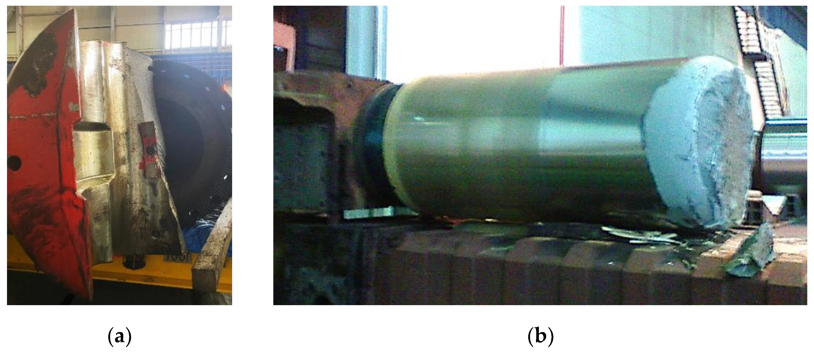
1.1. Causes of Intensive Wear of Spindle Joints

The low durability of elements of the main drive lines (main lines) of hot rolling stands is mainly caused by high dynamic loads arising during the workpiece biting. Here, a “workpiece” means an intermediate product between the billet (slab) and the finished product (strip or sheet). The problem of maintaining the performance of plate rolling stand electromechanical systems operating in the reverse mode with periodic accelerations and decelerations and shock loading is relevant. High dynamic loads lead to the early wear of equipment, which causes significant losses for the enterprise [12,13]. The most common failures occur in spindle joints, ensuring a mechanical connection between the spindle, roll, and motor. These failures are caused by the accumulated fatigue due to dynamic overloads [14]. Ref. [15] noted that the accumulated fatigue of spindle joint parts speeds up with increasing periodic shock loads.
Ref. [16] stated that for hot rolling mills, the maximum elastic torque on the main line motor section is 2–4 times more than the process torque required for a given draft. In this case, the transition from the dynamic torque of biting to the steady-state process torque occurs within 0.3–0.5 s and is accompanied by oscillations. This loading pattern negatively affects the strength of the main line parts and nodes, which concerns both one-time loading (overload) and fatigue phenomena. Spindle blades and rolls break, since elastic torque oscillations reduce the strength of mill parts [17].

1.2. Functions of Elastic Torque Monitoring System

Many scholars, in particular the authors of [18,19], have studied the issues of limiting the dynamic loads of rolling mills. Refs. [20,21] analyzed the causes of overloads during the biting. Refs. [22,23] were devoted to monitoring torques and forecasting the service life of electrical and mechanical equipment. Ref. [24] proposed to use angular and radial plays to diagnose the wear of drive mechanisms by analyzing transient processes. However, solving all these problems requires first “seeing” the dynamic torque on the spindle. Therefore, equipping mills with telemetry systems to monitor the elastic torque is an urgent scientific and practical problem.
Ref. [25] analyzed the known elastic torque monitoring systems usable for rolling mill spindles. A “digital strain gauge-based telemetry meter with contactless power supply has been developed, which can be used in rolling mills as part of stationary load monitoring systems”. It is concluded that a strain gauge circuit with digital data transmission via a radio channel as a frequency-modulated signal is acceptable for rolling conditions. Along with online monitoring of the load, the monitoring system is designed to monitor the equipment conditions and prevent accidents or determine their causes. Ref. [8] described a smart system for monitoring the remaining useful life of hot rolling equipment. It is noted that forecasting the service life of the electromechanical system of the stand is a related problem.
These conclusions correspond to the results of [9], where the key telemetry monitoring system application areas are as follows:
  • Diagnosing and forecasting the abnormal condition of the rolling mill drive system and analyzing the load;
  • Forecasting the service life of rolling mill equipment and implementing integrated diagnostic and control technology, which can be implemented at a single plant or facility;
  • Research related to technical condition forecasting and control.
This paper discusses the development and implementation of a telemetry elastic torque monitoring system to solve the first of these problems. Solving the second and third problems requires collecting and processing statistical data on the impact of dynamic loads on the spindle joint conditions. This is the subject of separate research and is therefore not discussed here.

1.3. Specifics of Known Elastic Torque Monitoring Systems

Scientific works [26,27,28,29] have been devoted to the development of techniques and systems for monitoring the condition of rolling stand mechanisms, including spindles. The most important problem to be solved when building online elastic torque monitoring systems is choosing the sensors and means of reading and transmitting signals to the server. Ref. [30] classified torque measurement techniques. It was emphasized that minimizing the mechanical noise in the transmission, protecting all devices from electrical interference, and choosing the proper sensor installation method are extremely important. Ref. [31] analyzed the principles of building elastic torque meters. Ref. [32] studied modern sensors. Ref. [33] considered the principle of measuring torques using bridge sensors and proposed a way to connect the sensor to external equipment.
Ref. [34] noted that “modern dynamic torque sensor operating principles are based mainly on strain gauges [35], acoustic interference [36,37], the effects of magnetic permeability and resistance [38,39], and optical polarization [39,40]”. It was noted that “existing technologies fail to satisfactorily solve the problem of connecting to a rotating sensing element, especially for transient conditions”. Ref. [41] described a torque measurement system based on strain gauges, which are the main means of obtaining signals of elastic deformations, torsional oscillations, and torsion of shafts. Ref. [42] developed a universal torque sensor for a transmission experiencing torque loading. Ref. [43] stated that “due to their easy integration, strain gauges are very popular in measuring torque by obtaining reliable data from moving objects”. A way for measuring torque on a rotating shaft using strain gauges and the factors affecting the measurement accuracy were considered. Ref. [44] also explored the reasons for the widespread use of strain gauges, describing the principles used to measure mechanical shaft torque and possible ways of mounting them, and analyzed their advantages and limitations. The provided analysis allowed for a conclusion on the feasibility of using strain gauges in the developed online elastic torque monitoring system.
The most important problem is to facilitate a long-term uninterrupted power supply to the measuring device. Ref. [45] considered a self-powered telemetry system for remote torque measurement and proposed a strain gauge-based self-powered telemetry meter. The digitally modulated electronic signal was transmitted from a remote conversion unit mounted on a rotating shaft to a base station sending signals to a PC using a virtual tool. A low-noise mechanism for powering the remote unit was developed, which eliminated the use of batteries and ensured system autonomy. This development is an analog of the monitoring system discussed herein.
In general, this literature review allows for the following conclusion: well-known publications have discussed the principles of monitoring elastic torques using telemetry systems but, as a rule, they have no information on their structures and hardware composition. Thus, the problem of developing and detailed consideration of an online monitoring system for the elastic torque on the rolling mill spindle is relevant. In a specific case, it is solved for a reversing stand of a plate Mill 5000. This paper is devoted to justifying the system-building principles and considering its structure and hardware composition, as well as the results of its industrial implementation.
This paper’s contents are given in the following sequence. Section 2 describes the research object—the electromechanical system of the plate mill stand 5000, showing the spindle structure, confirming the oscillatory nature of the elastic torque transients, and justifying the research objectives. Section 3 describes a structure explaining the concept of measuring, transmitting, and storing data in the system being built and justifies the modular system building principle. Section 4 discusses the structure of the data transmission and visualization system developed for the Mill 5000 and considers the functional modules of the measuring system and their location directly on the reversing stand spindles. Section 5 provides oscillograms of the elastic torque on the spindles and the maximum biting torque analysis results obtained with the designed and implemented drive control algorithms, and draws conclusions on a decrease in the spindle elastic torque when implementing an acceleration algorithm at biting. Section 6 provides a brief discussion of the results and highlights research prospects. Section 7 draws conclusions on this paper’s content.

2. Problem Formulation

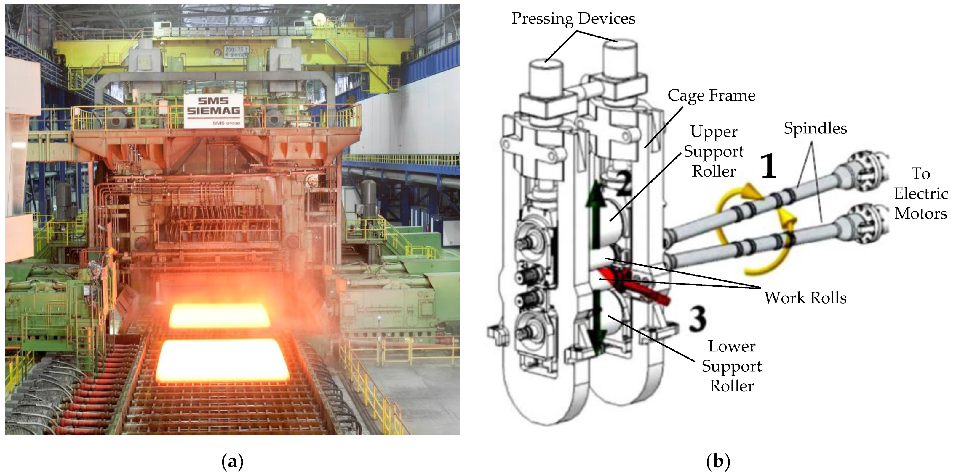
2.1. The Research Object Specifics

Figure 1 shows a photo of the horizontal stand of Mill 5000, taken as the workpiece exits the stand. The mill uses reverse rolling technology, where the primary rolling stage (roughing-down) is performed in batches of up to six billets. Ref. [46] provides the mill specifications and assortment and describes power equipment. Figure 1b [16] schematically shows the design of the stand with the upper and lower work roll spindles. The key specifications of the equipment are given in Table 1. The upper and lower roll drives are made individually based on synchronous motors with rpm control. A number of 12 MW motors are installed, providing a rated torque of 1.91 MN∙m. Ref. [47] considered the results of simulation and experimental study of transients occurring when the workpiece enters the stand. This mode, also called biting, is accompanied by a shock increase in the electrical and mechanical equipment loads and overloads with undesirable consequences.
According to the existing technology, the workpiece enters the stand at the threading speed (from 2 to 5 m/s), and then it is accelerated after emerging from the upward bend to a steady rolling speed. The slab mass is 30 tons or more; the initial thickness is 300–350 mm. Absolute drafting in the first passes is up to 30 mm. It is obvious that placing a workpiece with high inertia into the stand at the specified drafting leads to significant (often unacceptable) dynamic loads. Figure 1b shows the impacts on the stand at biting with arrows. The following dynamic torque components have been identified [16]:
  • Torque arising during rotation (main power line 1). When a shock load is applied, it has the nature of damped oscillations relative to the established rolling torque. The oscillation amplitude is determined by two factors:
    • Directly, by an impact resulting from the closure of angular gaps inevitably existing in mechanical transmissions;
    • Elastic properties of the transmission shaft, characterized by the elastic coupling factor of the rotating masses.
  • The vertical torque component (power line 2) determined by the rheological (deformation) metal properties and biting conditions. Without considering the uneven filling of the deformation zone, this component represents a useful rolling torque. It has the nature of shock loading without oscillations.
  • Horizontal component (power line 3), determined by the following:
    • The ratio of the speed of metal entry into the stand and the horizontal component of the linear speed of the rolls;
    • The inter-roll gap (indicated by arrow 3) set before biting.
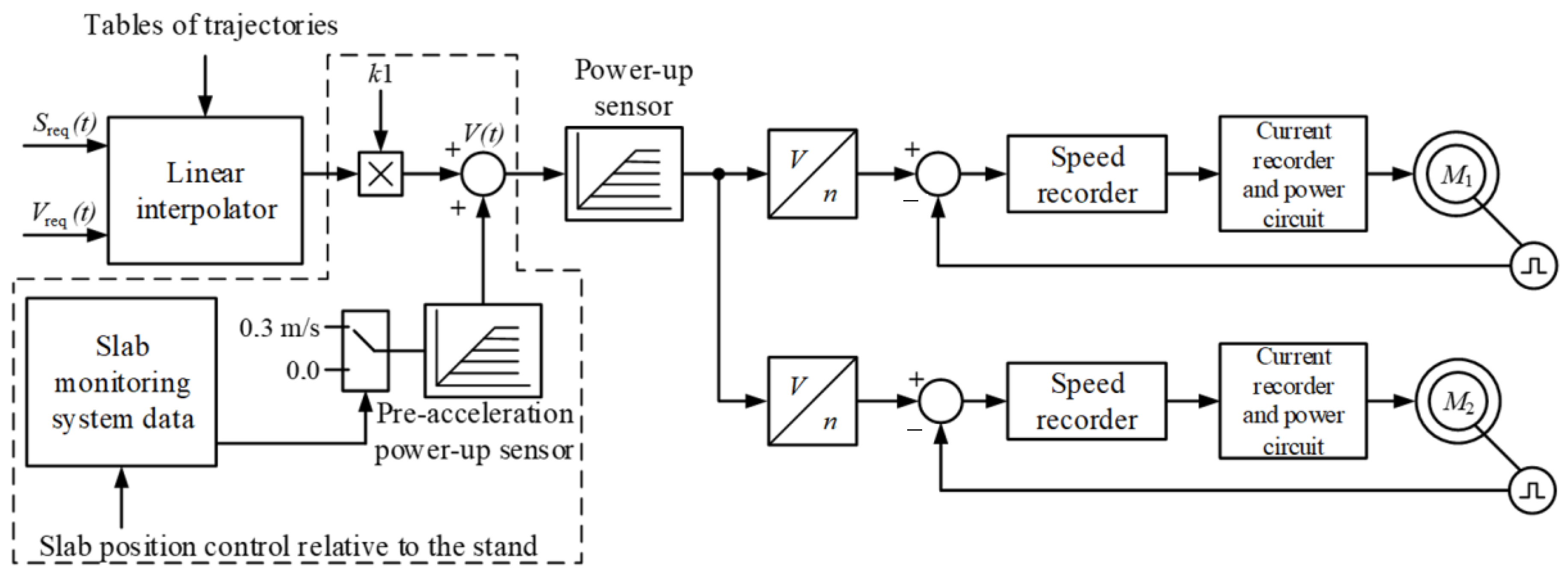
The horizontal component determines damped torque oscillations that tend to zero.
It is obvious that the listed factors determine the nature of the transient and the maximum value (amplitude) of the elastic torque on the spindle at biting. The amplitude is limited by means of automated stand drives. The control system performing this function, which is the author’s development, has been implemented at Mill 5000 and is described below.

2.2. Drive Control

Figure 2 shows a simplified block diagram of the main drive of a horizontal stand [48]. The pass trajectory is formed by the APCS model according to the criteria of mill performance and achieving the specified rolling temperature regime. The controller automatically sends the speed command Vreg(t), generating a table of desired movement trajectory points Sreg(t). The basic acceleration–deceleration rate is set by the interpolator. Its output signal of the target linear speed V(t) is sent to the power-up sensor (PS), ensuring the emergency limit of the rate. The PS output signal is converted, considering the roll diameters, into an angular drive speed command, which is sent to the input of the closed speed control loop.
The system implements a control method according to which biting is performed in the drive acceleration mode. This is achieved through the predictive acceleration (pre-acceleration) of the motor. It is implemented by connecting the blocks highlighted with a dashed line in Figure 2 to the design diagram: the pre-acceleration power-up sensor and the slab position control relative to the stand. The highlighted structure also comprises a mode switch ensuring the connection of a drive acceleration signal. Motor acceleration provides the closing of the gaps in the spindle joints (discussed below) before the workpiece enters the stand, thereby reducing the impact torque. Then, the pre-acceleration time is calculated based on the complete gap closure condition. To define the acceleration torque, the workpiece tracking system data are used. To generate the additional speed, the pre-acceleration PS output signal is summed with the interpolator output signal; the additional acceleration is 0.22 m/s2.
The algorithm is implemented in the stand controller. Operating practice has shown that with reliable identification of the pre-acceleration start and the proper choice of acceleration, this system ensures a reduction in the dynamic motor and mechanical equipment loads. In most cases, the torque amplitude decreases by 1.3–1.5 times; however, this conclusion has only been drawn based on an indirect assessment, since the direct measurement of the spindle elastic torque is not possible. To make it possible, a telemetry system for monitoring the spindle elastic torque should be developed, which is discussed herein.

2.3. Spindle Design

Figure 3a shows the spindle design photo [49]. It is connected to the roll using a head of a special design (Figure 3b) [23], attached to the working shaft, as shown in Figure 3a. A similar head is mounted on the motor side. Figure 3b schematically shows the closure of the angular gap δ. If the gap is open, then it closes at biting, being accompanied by mechanical shock and elastic torque oscillations. The strongest dynamic impacts occur on the stand side, which is caused by large reduced masses of the work and support rolls and the moving ingot inertia.
Research has shown that when metal enters the stand, the spindle elastic torque amplitude may exceed the steady rolling torque by 3–3.5 times. Considering that for “heavy” billet rolling, the torque is up to 200% of the rated motor torque (see Table 1), the said excess is 600–700%. This leads to the destruction of the spindle heads and roll necks [50]. Significant dynamic overloads in plate mills were confirmed in [51], where the processes occurring during the rolling of various steel grades at the Rolled Products Inc. (USA) mill were analyzed. This allowed for the conclusion that dynamic torque amplitudes can reach 1200% of the rated motor torque.
To reduce breakdowns at Mill 5000, threshold values were set for the emergency system: 6500 kN∙m to warn the operator and 8000 kN∙m for quick shutdown braking [12]. These parameters exceed the design values given in Table 1. However, direct dynamic shocks at biting rarely lead to breakdowns and emergency shutdowns of the mill. Breakdowns are most likely caused by accumulated cycles of torsional overloads, which lead to the fatigue failure of mechanical joints. Therefore, the most common accidents are spindle head (Figure 4a) and roll (Figure 4b) breakages. The elimination of their consequences is associated with long mill downtimes and significant costs.
Thus, the key causes of fatigue failures are oscillatory processes of torques in dynamic modes. This is confirmed by the oscillograms in Figure 5, reflecting an accident caused by the breakage of the lower stand roll connecting part (blade) at biting. Biting occurs at time instant t1; the electromagnetic torque of the lower roll motor (window 4) then reaches the limit level of 4200 kN∙m at time instant t2. The breakdown occurs at time instant t3, which is evident from the decrease in the lower motor torque from 4200 to 500 kN∙m. The upper roll motor tries to roll the workpiece alone, but its efforts are not enough; the drive passes into torque limit mode (window 2). The speed control loop opens, and slowly damping speed oscillations occur (window 1), caused by the spindle shaft elasticity. The motor speed settings (dependencies 1 in windows 1 and 3) are emergently reduced by a signal from the power-up sensor. The lower roll motor speed (dependence 2 in window 3) decreases at the same rate.
The provided oscillograms demonstrate the oscillatory properties of the “drive-roll” system. Under normal conditions, oscillations are superimposed on the impact gap closing, which increases the torque amplitude. The oscillograms show that under pre-emergency conditions, the roll drives pass into a torque-limiting mode, in which case, the spindle dynamic torques increase multi-fold. In addition, dynamic modes, as a rule, are preceded by elastic torque oscillations with an increasing amplitude [52]. However, they cannot be evaluated due to the lack of an elastic torque monitoring system.
The authors of [17,53,54] have drawn similar conclusions. A previous study [53] showed that the maximum torque under shock load application is 260% of the rated motor torque, while the calculated fatigue life is critical, since it is close to the actual spindle service life. Ref. [55] justified similar conclusions concerning the work rolls of a thin-strip hot rolling mill. It is concluded that to understand the roll destruction mechanism, improve its wear resistance, and extend its service life, the actual operating conditions should be analyzed.

2.4. The Analog’s Specifics

In 2011, a MANNER TG28TE elastic deformation measuring system produced by MANNER (Germany) was mounted on the investigated Mill 5000 stand [56,57]. Figure 6 shows oscillograms of torques on the upper and lower spindle shafts (window 1), torsional oscillations of the shaft lines (windows 2 and 3), and pressures in the hydraulic cylinders of the axial roll displacement (window 4) obtained with this system. They confirm that the dynamic torque amplitude, along with the shock loading, is determined by the elastic properties of the mechanical transmission. Damping oscillations of torques are observed with the maximum values occurring at the first peak after biting. Ref. [20] showed that the oscillatory process amplitude can be significantly higher than the component maximum of the torque caused by the gap closure in spindle joints.
An analysis of the oscillograms allows for the following conclusions:
-
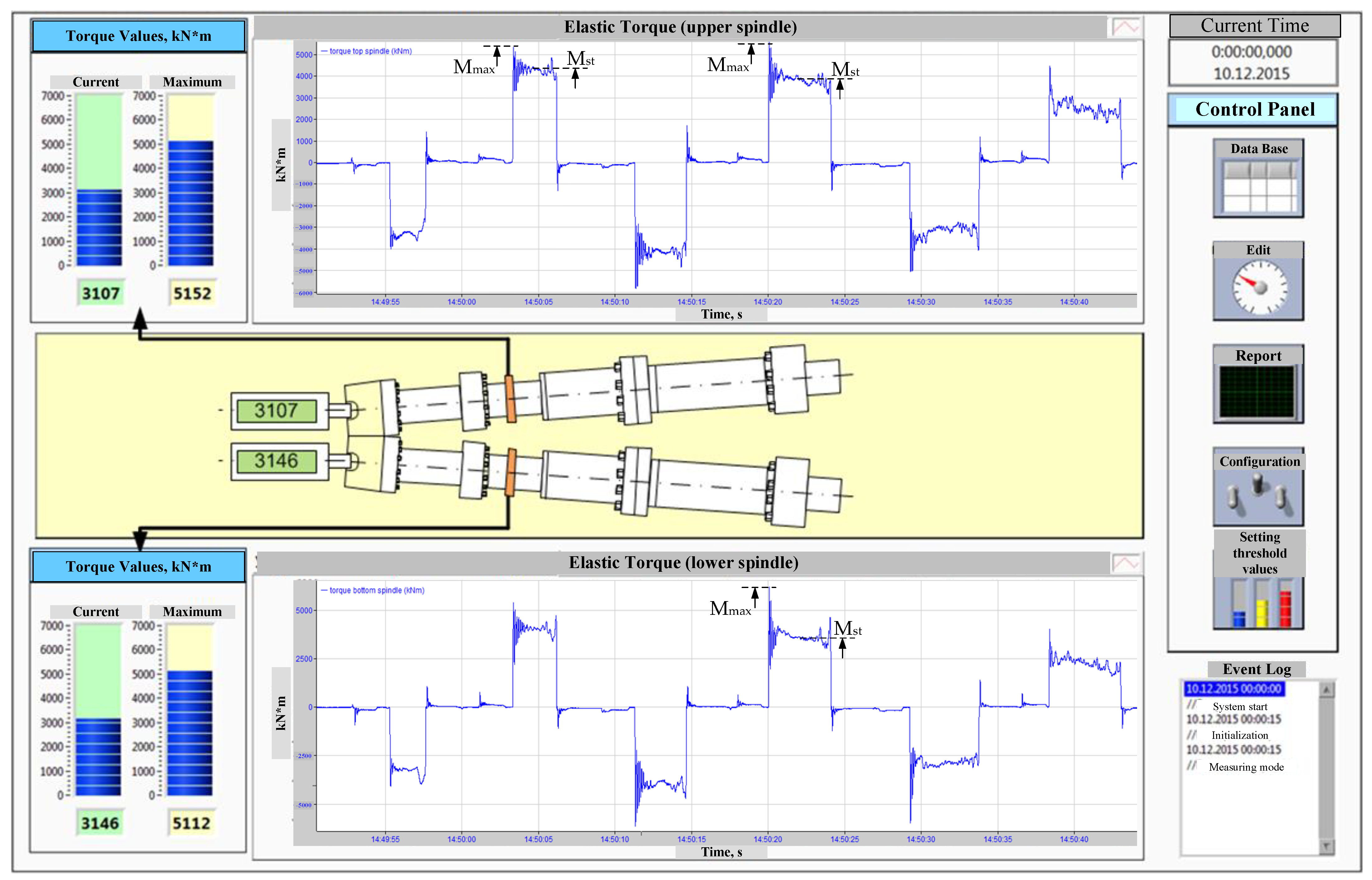
The impact torque amplitude (window 1) at biting exceeds the steady rolling torque by more than three-fold;
-
damping oscillations are superimposed on the sine wave (windows 2, 3) caused by the roll rotation and have the greatest amplitude on the lower spindle shaft (window 3).
In general, the system operation confirmed the efficiency of continuous elastic torque measurement. Thus, the conclusion on the advisability of online torsional oscillation control was recognized as ambiguous. This is due to the complexity of the physical interpretation and the use of this parameter for diagnostics.
Since this system failed, the problem of developing and implementing a similar system with a simple design and increased lifespan was set. The key requirements were to facilitate a relatively simple installation of the measuring equipment and for it to be self-powering. This should improve its reliability and durability.
Another important field of implementing the elastic torque online monitoring systems is worth highlighting, i.e., determining the fatigue wear of mechanical equipment, in particular, spindle joints. Scientific publications by many authors are devoted to this issue, including [14,58]. However, the existing studies were based on analytical dependencies, and the results have not been proven in practice. Thus, it is feasible and advisable to develop solutions aimed at eliminating this information gap.

2.5. Research Objectives

Experimental studies performed on Mill 5000 confirmed that the above conclusions are valid for the electromechanical systems of the horizontal stand of this mill. This allows for formulating the goals and objectives of further developments.
The research objective was to make a telemetry system facilitating continuous displaying, control, and analysis of the elastic torque on the horizontal Mill 5000 stand spindles. To achieve the objective, a set of scientific and practical problems was justified, including the following:
  • Developing a functional design and architecture of the system;
  • Choosing processor and hardware implementing the functions of measuring and displaying the elastic torque;
  • Developing technical solutions for the installation of sensors;
  • Adjusting and implementing the system;
  • Performing experimental studies to confirm the reduction in the elastic torque amplitude when implementing the stand drive pre-acceleration algorithm.
A problem of developing a technique for calculating the fatigue wear of mechanical equipment based on elastic torques measured by the implemented system was also set.

3. Materials and Methods

Based on an analysis of known developments, an online monitoring system for rolling mill spindles with individual roll drives was adopted as a prototype [8]. The principles of receiving, transmitting, and storing data used therein were applied in the system under study. Its advantage is the contactless way of transmitting the torque signal using an induction power source, ensuring stable powering and long-term continuous operation. The system representation as an open distributed structure with an architecture of remote condition monitoring in the field bus mode is justified [59,60]. The system should include the following modules (Figure 7): data acquisition, network communication, database server, condition monitoring and signaling, signal processing and analysis, and client–server module. The principle of strain gauge signal measurement is discussed, and the listed modules are described below.

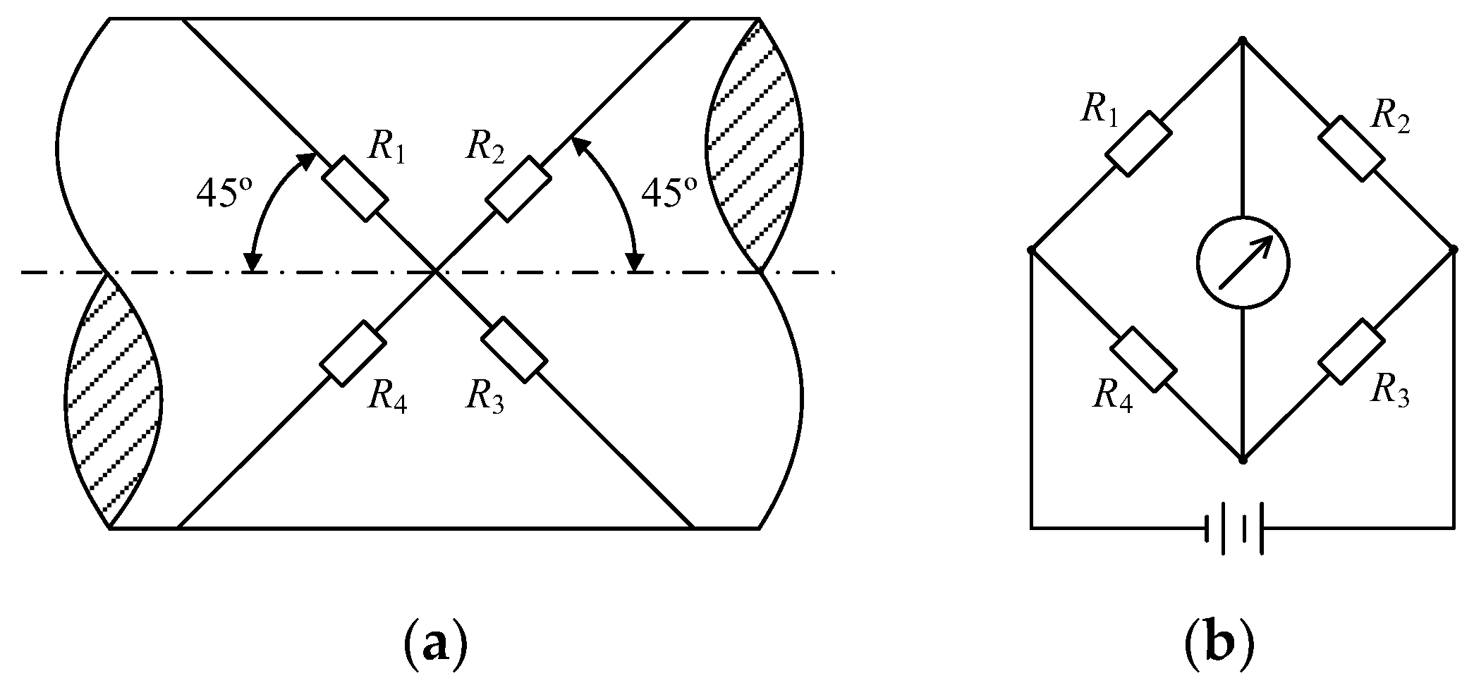
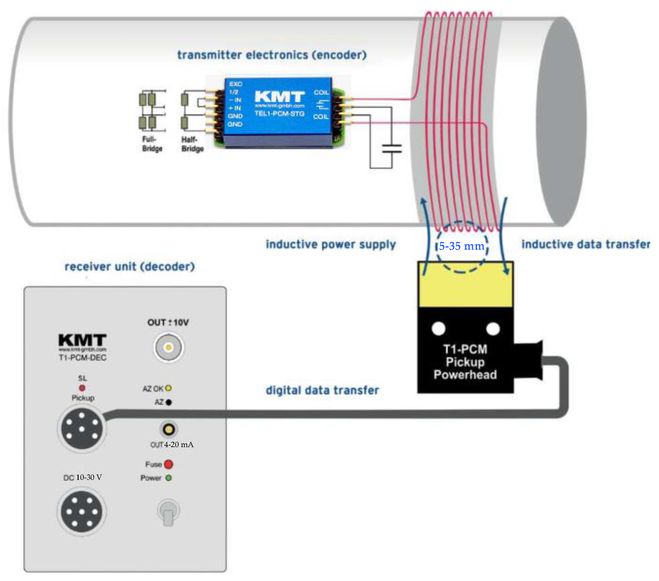
3.1. Strain Gauge Connection Circuits

Torque is known to cause 2D strain and stress in cylindrical rods [51], while the basic shear stress direction is at ~45° to the shaft axis (Figure 8a) [8]. The strain gauge operating principle is based on a change in resistance when the surface it contacts is deformed [29]:
dR/R = εS,
where R is electrical resistance; dR is the small change in electrical resistance; ε is deformation; and S is the strain gauge sensitivity.
Strain gauges are only sensitive to normal voltage depending on the length of their metal wires. Therefore, shear stress can be measured by placing strain gauges at angles of ±45° relative to the shaft axis. Therefore, for a solid shaft with diameter d, the torque can be defined by the formula
T = πGd3ε/8,
where T is the torque applied to the shaft, Nm; G is the material’s transverse elasticity modulus, MPa; and d is the diameter, m.
From Equations (1) and (2), the relationship between torque and the change in the strain gauge resistance dR is
T = πGd3ε/(8SdR/R.
Strain gauges are fixed to the shaft using special glue directly or on a special substrate; they are connected according to a balanced bridge scheme (Figure 8b). This allows for measuring changes in resistance of the bridge diagonals that occur under the impact of deformation forces.

3.2. Modular System Building Principle

Via an online torque telemetry device, the bridge output signals are transmitted to the integrated data acquisition module, and then, after processing, to a remote server via a USB interface. The technique has two ways of powering the rotating circuit: from a special battery and an induction power source. A battery-powered torque sensor can only operate for a relatively short time, so it can hardly be used in continuous monitoring. On the other hand, a similar inductively powered sensor has the required energy, which is transmitted through an electromagnetic coupling between the rotating and static coils. Such a source provides long-term stable powering and continuous system operation without the need to replace batteries. Therefore, it is advisable to use a sensor with such a power source in the system being developed.
The purpose of most of the blocks in Figure 7 corresponds to their names and does not require explanation. These include a contactless torque measurement system comprising a signal transmitter and receiver, a main monitoring system comprising a data acquisition module and servers, etc. The client’s browser contains engineering (staff) workstations and six blocks calculating and displaying controlled signals. Computation is an urgent requirement for a telemetry system, which follows from its definition above. Pre-processing includes filtering and the amplification of signals; similar operations are performed in most diagnostic monitoring systems. In an expanded version, diagnostics should provide automated time analysis; where appropriate, analysis of the signal shape and spectrum; and simulation and calculation of wear and fatigue life.
Depending on the requirements, the monitoring results should contain signals of the torque, force, rolling speed, and other process parameters. Computing modules compare them with threshold values, exceeding which should be displayed by alarms imported into the internal database. Monitoring trend changes is expedient to forecast the service life of the device; rolling power parameters and maximum and average measured values should also be displayed. These parameters are required to optimize rolling programs and develop new rolled products. The problem of assessing the efficiency of implementing the developed algorithm for limiting dynamic loads through pre-acceleration was also set (Figure 2).
A block for archiving and requesting archived data is required, since the volume of each sample is large, so the storage of measured and calculated coordinates should be ensured. Software development should adopt standard plug-in technology that makes it relatively easy to build and maintain a data system. The arrangement of the following databases is expedient [8]:
  • A regular database designed to store the peak and average values of rolling torque and forces. It provides real-time data storage, which facilitates online status analysis.
  • Alarm database, which serves to save diagnosed parameters in emergencies. In normal operation mode, it is replenished when the measured values exceed the alarm levels, and the data are read at the user’s request. Backup to the history database and cleaning (manual or automatic) when the database is full should also be provided.
  • A history database, the purpose of which is directly seen in its name. It can store measured or calculated parameters for a certain time, e.g., a month, to support queries and comparative analysis.
The advantage of the considered concept of the modular structure of a monitoring system is the possibility of using cloud data storage technologies. This is appropriate when the developed monitoring system will be part of a higher-level online control system, e.g., a workshop or factory system. The modular design principle makes it relatively easy to rebuild the system for specific facilities, staff requirements, and operating conditions. This is ensured by adding or excluding modules, which allows for optimizing its hardware without major software changes.
The considered concept was adopted as the basis for building a telemetry system for Mill 5000. The modules included in its structure are described below.

4. Implementation

The reliability of the data received from any telemetry system depends on the specifications of instruments and sensors. Considering the operating conditions, the following requirements for the system hardware are justified:
  • Providing reliable operation under hot rolling conditions, considering the required temperature range (900–1300 °C), dust and moisture protection, and vibration resistance under shock loads;
  • Power transmission to the measuring electronic components installed on the spindles and reading elastic torque signals from the rotating spindles should be contactless;
  • The design should be dismountable and allow the system to be mounted on a new spindle when replaced;
  • Electronic and processor system components should be electromagnetically compatible in terms of power and signal lines;
  • Measuring transducers should be able to control the elastic torque signal transmission factor of the measuring channel.

4.1. System Hardware

Figure 9 shows the structure of the developed online elastic torque monitoring system. It comprises the following components and instruments:
-
Strain gauge sensors and conversion units with contactless data transmission, mounted on spindles;
-
A receiver responsible for data acquisition;
-
A server for visualization, control, analysis, and database generation.
The telemetry system implements the wireless transmission of signals from strain gauge sensors installed on rotating shafts. The elastic torque signal is generated by a compact KMT encoder produced by KMT (Germany) [61], which is mounted in a ring with a measuring winding. The electronic components mounted on the shaft are powered and the digital data are transmitted from the encoder to the receiver (TEL1-PCM) inductively by generating a pulse code modulation signal in the induction winding. The signal generates a magnetic field, transmitting digital data to the system through an air gap. The layout of these instruments allows for minimizing the noise accompanying the measurement of weak signals.
The terminal-measuring part of the device is a decoder generating an analog elastic torque signal within ±10 V. The basic element for reading and digitizing elastic torque signals in the system is the NI USB-6351 multifunctional USB module produced by National Instruments (NI) [33]. This module is the latest generation of X-Series data acquisition (DAQ) devices capable of high performance. This is possible thanks to NI-STC3 and NI Signal Streaming technologies for synchronizing and generating high-speed data streams and multi-core optimization of drivers and application software.
The key properties and advantages of the measuring part of the system:
  • Possibility of using strain gauges (R > 350 Ohm) in full- and half-bridge configurations;
  • Inductive digital elastic torque data transmission from the rotating spindle to the measuring head through an air gap of up to 35 mm;
  • The measured signal frequency range of 0–1200 Hz;
  • Automatic receiver zeroing;
  • Setting the receiver gain within 250–8000;
  • External measuring channel calibration using a precision shunt;
  • No impact of radio frequencies on the measured elastic torque signal;
  • The ability to simultaneously work with several measuring systems;
  • Continuous conversion of instantaneous elastic torque values into an output analog signal within ±10 V;
  • A measuring channel error of less than 0.2%;
  • Easy assembly, configuration, and operation.

4.2. Functional Modules of the Measuring System

The choice of torque sensor primarily depends on its performance, physical requirements, and environmental conditions [33]. The developed system uses FCT-2-350-11 foil strain gauges with the following parameters:
  • Base 2 mm;
  • Resistance 350 Ohm;
  • Operating temperatures from −20 to +80 °C.
Such a strain gauge is a module containing two separate meters. Each module is connected to the input terminals of a KMT encoder (Figure 10), which provides wireless data transmission [62]. As shown in Figure 8a, the preferred way to measure shaft deformation is a bridge of four strain gauges. They are arranged on the spindle in diametrically opposed relative positions. Such a circuit improves the sensitivity and linearity of the resulting characteristic and significantly reduces the temperature impact on the output signal. The bridge’s other advantage is that it only measures the deviation and not the total resistance. The strain gauge input and output signals are connected to the encoder, which is a single-channel telemetry system.
The next step is the digital data transmission from the encoder to the T1-PCM receiver. Power is supplied to the transmitter side and digital data are transmitted to the receiver inductively. The T1 encoder (Figure 10) generates a digital signal via pulse code modulation, which is transmitted to the receiver head via an inductive winding around the shaft. Further, the signal is transmitted via cable to the receiver. As noted, the maximum distance between the transmitter coil and the receiver/power source head is 35 mm. The receiver has an analog output (±10 V) on the front as standard and can also be equipped with a current loop (4–20 mA). Automatic zeroing (auto-zero) can be started by pressing the AZ button on the front panel of the receiver. The TEL1-PCM-STG encoder produced by KMT was used, the specifications of which are given in Table 2 [61].
The reason for choosing this equipment was the statement that “the telemetry system in question is ideal for wireless transmission of strain gauge signals from rotating shafts” [61]. The converter electronics allow the direct full- and half-bridge connection of strain gauges. The bridge is powered with a fixed voltage of 4 VDC, and the gain can be freely chosen from four levels. Another advantage is its easy installation; it is stated that “the transmitter can either be fixed to the shaft using a special fiberglass-reinforced tape or installed directly into a ring housing adapted to the shaft within several minutes [61]”.
The transmitting and receiving equipment is fixed to the spindle shaft using the appliances shown in Figure 11. For reliable fastening and balancing around the spindle circumference, a special ring was used (Figure 11a) with a built-in transmitter (encoder) (Figure 11b) with an inductive winding. The inner ring diameter was made equal to the spindle shaft diameter with minimal tolerances. The inductive winding (Figure 11c) was designed to receive the encoder supply voltage and pick up the useful signal. Note: as practice has shown, the manufacture and installation of the collector ring with gluing the sensors is the most difficult stage in the system’s manufacture.
The advantage of this technical solution is that power is supplied to electronic components mounted on rotating shafts and elastic torque signals are read in a contactless mode by generating a pulse-code modulated signal in the air gap between the ring with the winding and the measuring head. According to Table 2, the system provides an elastic torque recording frequency of up to 1200 Hz, which significantly exceeds the 10–100 Hz range of the calculated spectrum of eigenoscillation of the main drive lines.

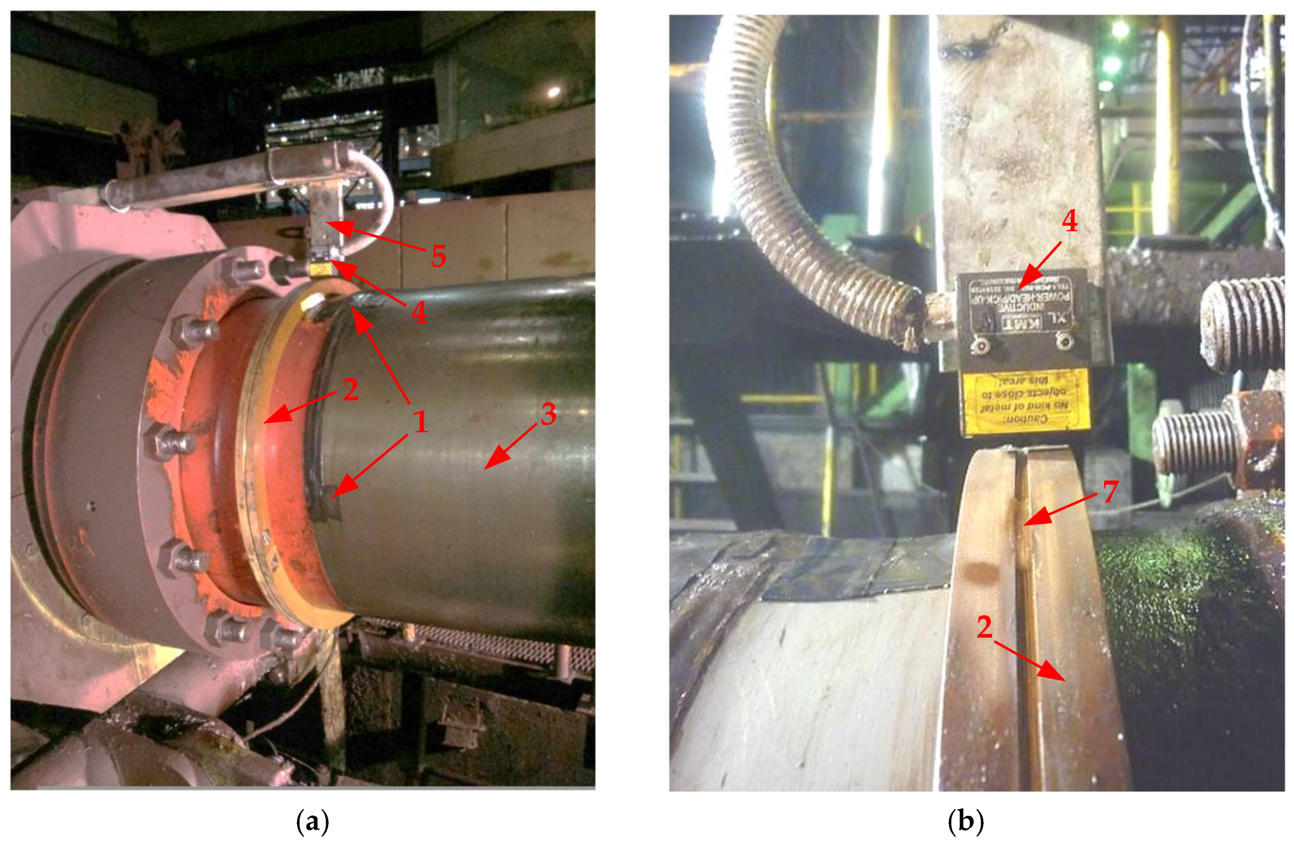
4.3. Industrial Implementation

The strain gauge bridge and detachable telemetric ring were mounted on the spindles of the work rolls in the area of the 715 mm cross-section; the mounting points are shown in Figure 12. As noted above, a high-quality installation of the sensor mounting appliance is required. This is because slipper-type spindles are installed to drive the rolls. The spindle shaft has a splined design to compensate for axial displacement when shifting the CVCplus rolls [63]. To operate in this mode, the spindle has a telescopic component and is moved during the rolling using a hydraulic cylinder. Therefore, it has a stroke and a slight inclination of the longitudinal axis (up to 5°) relative to the rolling line.
Figure 13a shows a photo that explains gluing strain gauge bridges (1) and installing detachable telemetric rings (2) on the upper roll spindle (3). The measuring head (4) is fixed through a slide (5) on a movable bearing support. Thus, a required constant air gap will be ensured between the rotating telemetric ring (2, Figure 13b) with the induction coil (7) and the stationary measuring head (4). Receivers (decoders) generating signals proportional to elastic torques and monitoring system processor hardware are located in a cabinet installed 20 m from the main drive lines, so they are not shown in the photos.
The instrument and the entire system were calibrated using laboratory equipment produced by PROMTEX (Moscow, Russia) [64]. Information on the KMT test benches is given in [58], and the principles of testing similar systems were discussed in [44,65]. After setting up and calibrating the system, several control measurements were made to accurately analyze the obtained strain gauge signals. The calibration showed that the measurement error was within ±5%.
The developed system has a special interface, the main window of which is shown in Figure 14. The screen shows oscillograms of torques on the upper and lower spindle shafts for six reverse rolling passes. The analysis of oscillograms obtained for the rolling of sheets of various profiles has shown that the average impact torque amplitude Mmax at biting is 1.5–2 times higher than the steady rolling torque Mst. Significant dynamic torques also arise when the workpiece exits the stand.

5. Results

The following fields of implementing the developed system in rolling mill electromechanical systems are justified here:
-
Analyzing dynamic loads arising during biting;
-
Diagnosing and forecasting emergencies;
-
Developing automated speed control systems providing for a reduction in dynamic loads by elastic torque feedback;
-
Calculating fatigue loads and the mechanical equipment lifespan.

5.1. Analyzing Impact Loads

To analyze the impact of pre-acceleration on transients when a shock load is applied at biting, Figure 15 shows oscillograms of the elastic torque on the lower roll motor shaft for three reverse rolling passes. Figure 15a represents rolling with the design algorithm for controlling drives without pre-acceleration, and Figure 15b shows similar processes with the implemented control system shown in Figure 2. The noise visible in Figure 15a when the torque is zero exceeds the noise in similar signal waveforms shown in Figure 15b. This is because the oscillograms in Figure 15b were obtained after additional signal smoothing, unlike the case shown in Figure 15a. From the perspective of further comparing the processes occurring during biting, the signal-to-noise ratio is irrelevant, so this inaccuracy does not affect the results.
To characterize dynamic processes, the dynamic factor kD is used, which is defined as the ratio of the maximum dynamic torque Mmax to the static torque Mst in the steady-state rolling mode:
k D = M max M st .
An analysis of the oscillograms allows for drawing the following conclusions.
1. Dynamic loads at biting in Figure 15a are equal to 150–160% of the steady-state value, with a dynamic shaft torque factor of kD = 1.5–1.6. As shown above, for a significant part of the mill assortment, the sheet rolling torque is 150–200% of the rated motor torque [20]. Therefore, the specified factor of exceeding the steady-state loads can lead to the opening of the speed control loop and is critical.
2. In Figure 15b, the dynamic factor was kD = 1.1–1.25; thus, it decreased by 1.3 times, which confirms the efficiency of implementing the pre-acceleration algorithm.
To summarize the results, dynamic factors of elastic torques on the upper and lower roll spindles were analyzed. They were fixed in different passes while rolling 140 sheets of different sizes (more than 1200 values). The rolling of approximately half of them was performed with the design control system, and the rest was rolled with the pre-acceleration control algorithm implemented. The average results are given in Figure 16, which shows diagrams of dynamic factors as a function of the workpiece thickness. They show that the reduction in the dynamic torque amplitude due to the implementation of pre-acceleration of rolls does not depend on the workpiece thickness and ranges within 15–32%. Thus, with a minimum thickness of 9 mm, the dynamic factor was reduced by 1.15 times (from kD = 1.55 to 1.35) due to pre-acceleration, and with an increase in thickness of 3.3 times (up to 30 mm), it was reduced by 1.23 times (from kD = 2.7 to 2.2). Similar ratios for intermediate thicknesses are given in Table 3. They confirm the technical efficiency of implementing the roll pre-acceleration algorithm for rolling sheets of any size.
In general, these results allow for drawing the following conclusions:
  • The developed elastic torque monitoring system allows for reliably assessing its dynamic deviations at biting.
  • Biting in the drive acceleration mode reduces dynamic loads on the spindle by eliminating impacts when angular gaps in spindle joints close. Before implementing the developed system, this conclusion could only be confirmed indirectly, in particular, using simulation.
  • The implementation of the system ensures continuous monitoring of the elastic torque, which improves the reliability of the rolling stand electromechanical systems.

5.2. Innovative Solutions

A technique for calculating the fatigue wear of spindle joints was developed based on the analysis of elastic torques obtained during rolling. Calculations were performed using data arrays recorded in the online mode. The oscillograms obtained in the study of elastic torques for individual passes confirmed the conclusion of high dynamic loads on the spindles when the workpiece enters the stand [66,67]. However, they were not statistically processed, and their impact on the spindle’s technical condition was not assessed.
Figure 17 shows oscillograms obtained during the 19-pass (5 passes of roughing and 14 passes of finishing) reversible rolling of a workpiece. They were recorded by the IBA PDA (Process Data Acquisition) system installed on the mill [68]. Windows 1 and 2 show speed oscillograms (nTMD and nBMD), while windows 3 and 4 show torque oscillograms (MTMD and MBMD) of the upper and lower roll drives. These dependencies were recorded during the rolling of heavy rolled stock: a tubular billet made of difficult-to-form steel with an initial roll drive speed mismatch (upward bend) of 15% [69].
The oscillograms show that in passes 5–15, the motor torques reach the ML limit, set at 4600 kN∙m. This leads to loss of the motor control, amplification of the drive’s oscillatory properties, and an increase in the spindle elastic torque amplitude at biting. However, Figure 17 does not show the spindle elastic torque dependencies. The oscillograms in windows 3 and 4 also show that the MTMD and MBMD torques differ by several-fold; therefore, the elastic torque amplitudes differed by several-fold as well. This is because they are affected by the speed of the workpiece entry into the stand and the magnitude of reductions, which vary in different passes [66]. However, the elastic torque amplitude’s dependency on the reduction (the pass number) still has not been analyzed. Such an analysis is the first task set in the study below.
The second task was to develop a technique for calculating the mechanical equipment’s lifespan under periodic dynamic loads. The task of a comparative analysis of the lifespan of TMD and BMD spindles under different loads by pass according to the oscillograms in Figure 17 was set. The “lifespan” term is here defined as the accrued operating time of the mechanism from the start of operation (or after repair) until it reaches the limit specified in regulatory and technical documents [70]. This parameter is measured as the number of load cycles or the duration of operation (in this case, years). The “remaining life” term refers to the change in these parameters from the start of the equipment’s operation (or repair) to the technical condition control moment.
For calculations, arrays of speed and torque data stored by the PDA system were exported to Matlab Simulink software (R2014a), where a spindle lifespan calculation controller was formed (Figure 18). It performs the following functions:
-
Counting spindle overload cases;
-
Shutdown when the spindle torque exceeds 400% of the rated value, since a breakdown may occur;
-
Counting the cases of the torque exceeding the 330% level for statistical analysis.
The rated motor torque was Mnom = 1.91 MN∙m; this value was taken as 100%. In the course of rolling, an overload of up to 200% is allowed with a limit set at 240%.
Using the algorithm of this controller based on the arrays formed by the PDA system, the amplitudes of elastic torque on the TMD and BMD spindles were calculated. The results are shown in Figure 19. The obtained data were used to calculate fatigue loads and the lifespan of mechanical equipment, for which purpose, a technique based on the linear Palmgren–Miner hypothesis [71] was developed.

5.3. The Fatigue Load Calculation Technique

According to the hypothesis mentioned, the following relationship is valid:
i = 1 K n i N i = 1 ,
where
  • n i is the number of cycles at the i-th load level;
  • N i is the number of cycles to failure at the same level;
  • K is the number of load levels.
It is assumed that each load exceeding a certain threshold reduces the lifespan by Δ n i . The fatigue curve is represented by the equation
N = C σ a m ,
where
  • C is the fatigue curve factor;
  • σ a is the stress amplitude;
  • m is the fatigue curve power parameter.
Instead of stress amplitudes, the use of spindle torque amplitudes is proposed (with C factors recalculated):
N = C M s p m ,
where M s p is the overload ratio by torque.
Considering this, the n i N i sum elements in Equation (4) are calculated for each load according to the following dependency:
n i N i = 1 C M s p m .
This dependency confirms the accelerated wear (remaining life) of one of the spindles under the loads shown in Figure 17, since the overload ratios of TMD and BMD spindles differ. To approximate the dependency (6), a power polynomial is proposed:
N = 1 10 9 M s p 12.01 ,
After substituting it into (7), the following equation is obtained:
n i N i = 1 C M s p m = 1 1 10 9 M s p 12.01 .
N = f( M s p ) (8) is a downward dependency, since it has a negative power exponent. Large exponents indicate a sharp decrease in the permitted number of load cycles with an increase in the spindle torque amplitude.
In the calculations, the following source data were used:
-
The rated service life of the spindle is 8 years, during which approximately 11,000,000 load cycles (passes) will occur (corresponding to 1,400,000 cycles per year);
-
The spindle has a safety factor of 7;
-
A 1.2-fold (and lower) dynamic torque will not cause spindle failure before the end of its lifespan.
Figure 20 shows the remaining life dependency on the torque ratio per pass, built according to equation (9) considering the accepted conditions. Its analysis allows for the following conclusions:
-
With a one-time load by a torque with an amplitude not exceeding four times the Mnom value, dynamic loads do not affect the spindle lifespan;
-
With a one-time load by a torque with an amplitude of 5.6Mnom, the spindle fails, since the remaining life becomes equal to one.
Then, the remaining life was calculated for the spindles per rolling cycle, with the distribution of elastic torques shown in Figure 19. The numerical values obtained for TMD and BMD were 0.00162 and 0.00015, respectively. Thus, the consequence of uneven dynamic loading is a 10-fold difference in the remaining life of spindles.
Figure 21 shows the remaining life plots for 2,800,000 load cycles, corresponding to 2 years of operation according to the rated preventive shutdown schedule. Herewith, source data for more than 116 thousand billets of various grades were analyzed. The lifespan is plotted on the vertical axis in relative units (r.u.), with the maximum number of load cycles for the rated operating period, equal to 11,000,000, taken as the base value. The obtained data were processed automatically according to the aforementioned technique.
According to the plots, after 2 years of operation, the BMD spindle’s remaining life will be 0.58 r.u., while for the TMD spindle it will be 0.43 r.u.; thus, the ratio is 1.35. When extrapolating these dependencies to intersect with the horizontal axis, the TMD spindle’s full lifespan will be 3.5 years, while for the BMD spindle it will be 4.5 years. These terms are approximately two times shorter than the spindle’s specified rated service life (8 years), which is the reason for developing measures to limit the mill stand’s dynamic loads. The implementation of a control system facilitating biting in the drive acceleration mode is among such measures (Figure 2).
The provided results confirm the possibility of calculating the remaining life of the mill stand equipment based on experimental data using the Palmgren–Miner hypothesis. To reliably assess the remaining life, data on the elastic torque amplitudes, the number of cases of the torque exceeding the rated value (1.2Mnom), and other values required for calculations according to the technique outlined should be collected and stored. This can be achieved using the developed system (Figure 9) and the lifespan calculation controller (Figure 18).
Since more than 50,000 billets of various grades are rolled annually, with approximately 27 passes (totaling 1.4 million bites) per billet, it is advisable to implement cloud technologies for reliable monitoring of the mill stand equipment condition. Furthermore, the resources of big data should be used, such as statistics, spatial analysis, semantics, interactive learning, visualization, etc.
The described technique is characterized by simplicity, which allows for the calculation of the spindle lifespan online. Similar developments were not found in the references.

6. Discussion of the Results and Future Work

6.1. The Developed System Implementation Results

The developed spindle elastic torque online monitoring system is recommended for industrial implementation in mills with electromechanical systems operating with an impact load when workpieces enter the stands. Along with the reversing stands of thick sheet mills, these include roughing stands of wide-strip and shape hot mills and tube rolling mills. The implementation of similar systems is recommended for the electromechanical systems of stands and reels of cold rolling mills. In this case, the elastic torque data are required to assess the condition of the stand mechanisms and, primarily, the reducers. These systems are also expedient for monitoring the vibrations of stands and reels, which are informative diagnostic characteristics of the condition of engines and mechanical equipment [72,73,74].
The general principles of reading, transmitting, and processing the torque data implemented in the developed system can be used in developing similar systems for other facilities equipped with long shafts that transmit rotational torque from motors to actuators. These include ship propulsion shafts [75,76,77,78], robotics systems [79], car transmissions [80], etc.
There are no scalability issues with the system in terms of simultaneously monitoring multiple spindles, including when installing the system on multi-stand mills. This is because the spindle torque data for all stands are sent to the central server via independent digital communication channels. After processing, these data become accessible via the Ethernet to all workstations of the service departments. This allows for arranging the required number of data channels over the network.
The procedure for processing and analyzing data is performed by the server software. The software comprises modules implementing the AI functions, including machine learning elements. These include self-learning elements, continuous testing of measurement accuracy, and monitoring of hardware and software failures in the system. As operational experience accumulates, the developed software is improved, and its description may become the subject of a separate publication.

6.2. Feasibility Study

The developed system is an analog of the instruments discussed in [8,25]. A comparative analysis of these systems in terms of accuracy, reliability, and economic efficiency was not possible due to the lack of reliable data on these indicators. However, they are built on the principle of strain gauge elastic torque measurement with contactless signal reading. Thus, it is logical to assume that their reliability indicators are equivalent.
The feasibility of the developed data measuring system can be correctly analyzed by comparing it with the aforementioned MANNER system (an analog) operated on the same Mill 5000. The proposed development operation practice confirmed its high reliability. This system had been operating for over five years, while the analog’s lifespan (with the same maintenance) did not exceed 3 years. This is explained by more reliable instrument fixing, the lack of power batteries, the high noise immunity of signals, and the experience accumulated during the analog operation.
According to the warranty obligations, the lifespan of all KMT components is at least 10 years. The most vulnerable part of the system is the strain gauges, which are glued onto the shaft. The frequency and norms of the system equipment maintenance are regulated by terms of reference developed considering harsh operating conditions and a negative environmental impact. Obtaining detailed data on the lifespan of individual components requires collecting statistical data with a long-term perspective, which is a prospective task.
The key reason for such systems’ failure Is the human factor, since the precision equipment operation requires a high level of maintenance culture. The measurement reliability and accuracy largely depend on the quality of gluing strain gauge sensors and the measuring ring installation accuracy. The need for these labor-intensive operations arises with each scheduled spindle replacement. The practice has shown that when the staff is attentive to these issues, the precision system lifespan increases.
Operating condition factors also affect the system’s lifespan. These primarily include the temperature, humidity, and vibrations caused by impact loading. Dustiness is a less significant factor. However, according to the photos in Figure 13, the impact of humidity and temperature is not critically significant due to the remote sensor location from the stand. Herewith, the impact of these factors cannot be completely eliminated, so elastic torque online monitoring systems are being developed considering heavy operating conditions.
The developed system provides for the following measures (compensatory mechanisms) to reduce the negative impact:
1. The use of dual-grid strain gauges, which achieve the following:
-
Reduce the impact of temperature differences on the output signal magnitude;
-
Improves the response;
-
Provide the linearity of the obtained characteristic.
2. Special coatings for strain gauges under conditions of increased humidity. Such protection is required to protect the strain gauges from damage and maintain insulation resistance. Under normal conditions, the insulation resistance of the glued strain gauge should be a minimum of 100 MΩ.
3. Strain gauges can also be protected by applying several layers of moisture-resistant adhesives. Under very high humidity conditions, coatings based on bitumen, rosin, wax, and epoxy resins are used. Good moisture insulation is provided by the Vixint K-68silicon-organic compound.
4. Tokyo Sokki Kenkyuio CO’s products (Japan) were used to protect strain gauges against harmful factors when attaching them to the shaft:
-
Bonding pads for strain gauges for operating temperatures of −196… +180 °C;
-
Special EB-2 adhesive for strain gauges;
-
Two-component epoxy composition for metals and composite materials, designed for operating temperatures of −30… +150 °C, and some other components.
5. Araldite 2011 epoxy resin-based (Huntsman, USA) protective coating was used to protect strain gauges from mechanical damage; operating temperature: −60… +100 °C.
To easily reinstall the ring on a new spindle, it has a detachable design. The ring’s structure and the elements fastening its detachable parts should withstand the loads arising at the spindle’s angular speed of 250 rpm.
The economic efficiency of implementing the system can be assessed positively. According to [81], preventing at least one moderate-severity accident on a responsible metallurgical unit covers the cost of up to 20 online process parameter monitoring systems. Thus, the initial cost of the implemented system is not a significant indicator.
The implemented system achieves the following:
-
Reduces the mill downtime due to the main drive line equipment failures;
-
Optimizes deformation-speed profiles between passes when rolling new shapes or improving technology;
-
Records and analyzes events causing accidents;
-
Identifies trends and detects hidden causes of malfunctions;
-
Evaluates the remaining life of parts subject to fatigue failure to arrange repairs depending on the damage.
Reducing downtime is the determining factor in assessing cost efficiency. The system operation practice has confirmed the following:
-
An increase in the spindle lifespan by at least two times (from 3–4 years to rated 8 years);
-
A reduction in downtime due to mechanical spindle joint failures by 25–30 h per year;
-
With an average mill yield of 150 tons/h, it increases the output by 3.8–4.5 thousand tons.
These figures are approximate, since any commercial data of the enterprise are confidential. As noted above, considering the high cost of the finished product, direct costs for installation and maintenance are not critical in assessing economic efficiency.

6.3. Research Prospects

Operating a torque monitoring system would prevent catastrophic damage from accidents and reduce the costs of rolling mill downtime. The system provides maximum, minimum, and root-mean-square torque values directly during the rolling. Their analysis allows the configuration of a torque prediction model, thereby defining the limitations imposed by the drive on the process. Comparing the calculated values with test results allows the optimization of rolling programs and parameters (speeds, drafting, etc.). This is required to improve the rolling rhythm, improve the performance, and protect the mill equipment. It is also expedient to use the data obtained when developing new rolling profiles.
Implementing a telemetry system opens up prospects for the following developments:
  • Techniques for controlling the speed modes of horizontal stand drives, ensuring the limitation of dynamic loads at biting;
  • A closed roll speed direct control system, ensuring the limitation of the spindle elastic torque when a shock load is applied.
  • Observers of the two-mass system state based on continuously measured drive coordinates [12,46].
To further develop the system in question, increasing the number of recorded signals is expedient. It is advisable to simultaneously record the roll speed, electrical parameters (currents, rolling forces, etc.) read by the IBA PDA, and the signals from pressure sensors in the hydraulic cylinders of the vertical balancing of spindles [52]. In combination with a system for recording angular gaps in spindle joints [49], this will allow the building of a universal system for diagnostic monitoring of the main stand line mechatronic equipment conditions. Attention should also be paid to the development of techniques and algorithms for calculating fatigue wear and the life of spindles based on a set of measured parameters. As for the monitoring of the spindle joint conditions, previous studies [58,82] should be noted; papers [83,84] were devoted to assessing the residual life; however, they cannot be directly applied in online monitoring systems. These issues require separate studies, the results of which may be the subject of future publications.
Solving these problems requires an integrated approach and an in-depth theoretical analysis. However, the most important and costly part—developing an elastic torque monitoring system—has been completed.

7. Conclusions

  • The available techniques and instruments for measuring the torque of rolling mill electromechanical systems have been analyzed. The concept of building a telemetry system for online monitoring of elastic torque using a modular principle was justified. The advantages of this approach were noted, with the major ones being its simplicity and the possibility of convenient modification of the structure based on the diagnosed facility specifics and the staff requirements. The proposed modular structure is recommended for use in building systems for monitoring the condition of various industrial equipment.
  • A digital telemetric spindle torque meter was developed based on strain gauges connected according to a balanced bridge circuit with contactless powering. The meter can be used as part of stationary load monitoring systems. Technical solutions for the arrangement and installation of sensors and signal converters were developed; processor equipment and hardware were chosen to facilitate power transmission to the measuring electronic components. They provide an inductive reading of rotating spindle elastic torque signals and generate an output voltage of ±10 V, proportional to the elastic torque.
  • A functional diagram and hardware structure of a system for continuous monitoring of the elastic torque on the Mill 5000 stand horizontal roll spindles were developed considering the drive design parameters, specifications, and operating modes. The system was integrated into a data network combining a visualization server and hardware processors.
  • The system was configured and implemented. The efficiency of its implementation was experimentally confirmed when testing a control algorithm reducing dynamic loads on the spindle due to the pre-acceleration of the drive.
  • The technique for calculating the lifespan based on the linear Palmgren–Miner hypothesis was considered, and analytical dependencies explaining the calculations were provided. The lifespan dependency on the torque ratio at a one-time loading was analyzed. It was shown that the difference in the TMD and BMD spindle loads per rolling cycle (19 passes) resulted in differences in their lifespan. The results of the automated lifespan calculation by processing data arrays obtained for a month during the rolling of real stock sheets were provided.
  • Based on the elastic torque analysis, dependencies have been built, characterizing the difference in expected TMD and BMD spindle lifespans over 2 years. Extrapolation showed that the complete TMD spindle’s depletion will occur after approximately 3.5 years, while for the BMD spindle it will occur after approximately 4.5 years. Such short lifespans serve as grounds for developing technical solutions aimed at limiting the dynamic loads on spindles at biting.
  • The implementation of the online monitoring system for elastic torques on the rolling stand spindles achieves the following:
    • It reduces emergency downtime caused by breakdowns of the mechanical equipment of stands;
    • Reduces costs for eliminating the consequences of accidents and replacing and restoring damaged equipment;
    • Increases the service life of electrical and mechanical equipment through monitoring and limiting shock loads at biting.
Telemetry monitoring systems can be transformed into cyber-physical systems [85,86]. This statement fully applies to the developed system. Currently, based on this, a cyber-physical system is being developed, which will be first implemented at an operating rolling mill. The principle of its building is recommended for various industrial equipment condition monitoring systems.

Author Contributions

Methodology, A.S.K., V.R.K. and S.S.V.; ideas, A.S.K., S.A.E. and B.M.L.; software, B.M.L., S.S.V. and O.A.G.; validation, B.M.L. and O.A.G.; formal analysis A.S.K. and V.R.K. All authors have read and agreed to the published version of the manuscript.

Funding

This work was financially supported by the Moscow Polytechnic University within the framework of the grant named after Pyotr Kapitsa.

Data Availability Statement

Data are contained within the article.

Conflicts of Interest

Olga A. Gasiyarova is employee of the company RTC «InTech» LLC. The remaining authors declare that the research was conducted in the absence of any commercial or financial relationships that could be construed as a potential conflict of interest.

References

  1. Predictive Precision: How Condition Monitoring Transforms Maintenance Strategies in Industry 4.0. Available online: https://www.pragmaworld.net/predictive-precision-how-condition-monitoring-transforms-maintenance-strategies-in-industry-4-0/ (accessed on 23 January 2024).
  2. Del Castillo, A.C.; Sasidharan, M.; Nentwich, C.; Merino, J.; Parlikad, A.K. Data-Driven Asset Health Index—An application to evaluate Quay Cranes in container ports. Marit. Policy Manag. 2023, 1–19. [Google Scholar] [CrossRef]
  3. Li, Q.; Yang, Y.; Jiang, P. Remote Monitoring and Maintenance for Equipment and Production Lines on Industrial Internet: A Literature Review. Machines 2023, 11, 12. [Google Scholar] [CrossRef]
  4. Panayanthatta, N.; Clementi, G.; Ouhabaz, M.; Costanza, M.; Margueron, S.; Bartasyte, A.; Basrour, S.; Bano, E.; Montes, L.; Dehollain, C.; et al. A Self-Powered and Battery-Free Vibrational Energy to Time Converter for Wireless Vibration Monitoring. Sensors 2021, 21, 7503. [Google Scholar] [CrossRef] [PubMed]
  5. Morgan, J.; O’Donnell, G.E. Cyber physical process monitoring systems. J. Intell. Manuf. 2015, 29, 1317–1328. [Google Scholar] [CrossRef]
  6. Yang, X.; Luo, H.; Krueger, M.; Ding, S.X.; Peng, K. Online Monitoring System Design for Roll Eccentricity in Rolling Mills. IEEE Trans. Ind. Electron. 2016, 63, 2559–2568. [Google Scholar] [CrossRef]
  7. Peng, R.; Zhang, X.; Shi, P. Bearing Fault Diagnosis of Hot-Rolling Mill Utilizing Intelligent Optimized Self-Adaptive Deep Belief Network with Limited Samples. Sensors 2022, 22, 7815. [Google Scholar] [CrossRef] [PubMed]
  8. Hou, Y.; Kong, J.Y.; Wang, X.D. Research on Online Monitoring for the Main Drive System of Rolling Mill. Appl. Mech. Mater. 2011, 127, 444–448. [Google Scholar] [CrossRef]
  9. Shin, N.; Shin, K.; Bae, J. A Study on the Health Monitoring of Hot Rolling Mill. Review of Progress in Quantitative Nondestructive Evaluation. Available online: https://www.iastatedigitalpress.com/qnde/article/id/8686/ (accessed on 23 January 2024).
  10. Kim, E.S. Fatigue life evaluation of spindle of rolling mill using ADINA structure and WINLIFE. J. Mech. Sci. Technol. 2020, 34, 3991–3996. [Google Scholar] [CrossRef]
  11. Krot, P.; Prykhodko, I.; Raznosilin, V.; Zimroz, R. Model Based Monitoring of Dynamic Loads and Remaining Useful Life Prediction in Rolling Mills and Heavy Machinery. Adv. Asset Manag. Cond. Monit. Smart Innov. Syst. Technol. 2020, 166, 399–416. [Google Scholar] [CrossRef]
  12. Gasiyarov, V.R.; Radionov, A.A.; Loginov, B.M.; Karandaev, A.S.; Gasiyarova, O.A.; Khramshin, V.R. Development and Practical Implementation of Digital Observer for Elastic Torque of Rolling Mill Electromechanical System. J. Manuf. Mater. Process. 2023, 7, 41. [Google Scholar] [CrossRef]
  13. Gasiyarov, V.R.; Radionov, A.A.; Loginov, B.M.; Zinchenko, M.A.; Gasiyarova, O.A.; Karandaev, A.S.; Khramshin, V.R. Method for Defining Parameters of Electromechanical System Model as Part of Digital Twin of Rolling Mill. J. Manuf. Mater. Process. 2023, 7, 183. [Google Scholar] [CrossRef]
  14. Xu, H.; Cui, L.-L.; Shang, D.-G. A study of nonlinear coupling dynamic characteristics of the cold rolling mill system under different rolling parameters. Adv. Mech. Eng. 2017, 9, 168781401771370. [Google Scholar] [CrossRef]
  15. Kravchenko, V.M.; Sidorov, V.A.; Butsukin, V.V. Wear of the Blades of the Universal Rolling Mill Spindle. Bull. Azov State Tech. Univ. Ser.Tech. Sci. 2012, 24, 262–265. Available online: http://nbuv.gov.ua/UJRN/vpdty_2012_24_42 (accessed on 23 January 2024).
  16. Artyukh, V.G. Fundamentals of Protection of Metallurgical Machines from Breakdowns; University Publishing Group: Mariupol, Ukraine, 2015; 288p. [Google Scholar]
  17. Domazet, Z.; Luksa, F.; Susnjar, M. Failure analysis of rolling mill stand coupling. Eng. Fail. Anal. 2014, 46, 208–218. [Google Scholar] [CrossRef]
  18. Popenda, A.; Lis, M.; Nowak, M.; Blecharz, K. Mathematical Modelling of Drive System with an Elastic Coupling Based on Formal Analogy between the Transmission Shaft and the Electric Transmission Line. Energies 2020, 13, 1181. [Google Scholar] [CrossRef]
  19. Nalepa, R.; Najdek, K.; Wrobel, K.; Szabat, K. Application of D-Decomposition Technique to Selection of Controller Parameters for a Two-Mass Drive System. Energies 2020, 13, 6614. [Google Scholar] [CrossRef]
  20. Gasiyarov, V.R.; Khramshin, V.R.; Voronin, S.S.; Lisovskaya, T.A.; Gasiyarova, O.A. Dynamic torque limitation principle in the main line of a mill stand: Explanation and rationale for use. Machines 2019, 7, 76. [Google Scholar] [CrossRef]
  21. Bhowal, P.; Mukherjee, S.K. Modeling and Simulation of Hidraulic Gap Control System in a Hot Strip Mill. ISIJ Int. 1996, 5, 553–562. [Google Scholar] [CrossRef]
  22. Ohlert, J.; Sprock, A.; Sudau, P. Digitalization in hot and cold rolling mills. Mat. Sci. Forum 2016, 854, 215–224. [Google Scholar] [CrossRef]
  23. Krot, P.V. Hot Rolling Mill Drive Train Dynamics: Torsional Vibration Control and Backlash Diagnostics. Millennium Steel China. 2009. Annual Issue. pp. 91–95. Available online: https://www.researchgate.net/publication/202044159_Hot_rolling_mill_drive_train_dynamics_torsional_vibration_control_and_backlashes_diagnostics (accessed on 23 January 2024).
  24. Krot, P.V. Nonlinear Vibrations and Backlashes Diagnostics in the Rolling Mills Drive Trains. In Proceedings of the 6th EUROMECH Nonlinear Dynamics Conference (ENOC), St. Petersburg, Russia, 30 June–4 July 2008; pp. 360–365. [Google Scholar] [CrossRef]
  25. Krot, P.V. Telemetry Systems for Monitoring Dynamic Loads in Drive Lines of Rolling Mills. Machine Vibration: Measurement, Reduction, Protection: Collection of Scientific, Technical, and Production Papers. Donetsk: DonSTU, 2008. Iss. 1. pp. 30–41. Available online: https://www.researchgate.net/publication/330779240_Telemetriceskie_sistemy_monitoringa_dinamiceskih_nagruzok_v_liniah_privoda_prokatnyh_stanov_Telemetering_Systems_for_Monitoring_Dynamic_Loads_in_Drive_Lines_of_Rolling_Mill (accessed on 23 January 2024).
  26. Gao, Y.; Jin, B.; Zhang, H. Wireless Remote Monitoring System for the Agc Svibration Fault of Rolling Mill. J. Appl. Sci. 2013, 21, 4875–4880. [Google Scholar] [CrossRef]
  27. Yukio, K.; Yasuhio, S.; Nobuo, N.; Naoki, I.; Yutaka, M. Analysis of chatter in tandem cold rolling mills. ISIJ Int. 2003, 43, 77–84. [Google Scholar] [CrossRef]
  28. Rothera, A.; Jelali, M.; Soffker, D. A brief review and the first application of time-frequency-based analysis methods for monitoring of strip rolling mills. J. Process Control 2015, 35, 65–79. [Google Scholar] [CrossRef]
  29. Kowalak, P.; Borkowski, T.; Bonislawski, M.; Holub, M.; Myskow, J. A statistical approach to zero adjustment in torque measurement of ship propulsion shafts. Measurement 2020, 164, 108088. [Google Scholar] [CrossRef]
  30. Goszczak, J. Torque measurement issues. IOP Conf. Ser. Mater. Sci. Eng. 2016, 148, 012041. [Google Scholar] [CrossRef]
  31. Krimmel, W. Evolution and Future of Torque Measurement Technology. Available online: https://www.lorenz-messtechnik.de/english/company/torque_measurement_technology.php (accessed on 23 January 2024).
  32. Innovative Sensor Telemetry—The Revolutionary Solution for Industry 4.0. Available online: https://www.sensortelemetrie.de/en/innovative-sensor-telemetry-the-revolutionary-solution-for-industry-4-0/ (accessed on 23 January 2024).
  33. Measuring Torque with Bridge-Based Sensors. NI Is Now Part of Emerson’s New Test & Measurement Business Group. Available online: https://www.ni.com/en/shop/data-acquisition/sensor-fundamentals/measuring-torque-with-bridge-based-sensors.html (accessed on 23 January 2024).
  34. Mateev, V.; Marinova, I. Magnetic Elastomer Sensor for Dynamic Torque and Speed Measurements. Electronics 2021, 10, 309. [Google Scholar] [CrossRef]
  35. Myers, D.R.; Pisano, A.P. Torque measurements of an automotive halfshaft utilizing a MEMS resonant strain gauge. In Proceedings of the TRANSDUCERS 2009 International Solid-State Sensors, Actuators and Microsystems onference, Denver, CO, USA, 21–25 June 2009; pp. 1726–1729. [Google Scholar] [CrossRef]
  36. Shvetsov, A.; Zhgoon, S.; Lonsdale, A.; Sandacci, S. Deformation sensitive cuts of quartz for torque sensor. In Proceedings of the IEEE International Ultrasonics Symposium, San Diego, CA, USA, 11–14 October 2010; pp. 1250–1253. [Google Scholar] [CrossRef]
  37. Zi, X.; Zhao, S.; Geng, S.; Wu, L.; Pang, H. A Wireless Torque Sensor Based on Surface Acoustic Wave. In Proceedings of the International Conference on Wireless Communication and Sensor Network, Wuhan, China, 13–14 December 2014; pp. 326–329. [Google Scholar] [CrossRef]
  38. Muro, H.; Saito, C.; Shimada, M.; Furuya, Y. Magnetostrictive-ring type torque sensor using two Hall ICs with differential magnetic field detection. In Proceedings of the IEEE Sensors, Valencia, Spain, 2–5 November 2014; pp. 412–415. [Google Scholar] [CrossRef]
  39. Wang, Y.; Jang, W.; Huang, C. Lightweight Torque Sensor Based on a Gradient Grating Period Guided-Mode Resonance Filter. IEEE Sens. J. 2019, 19, 6610–6617. [Google Scholar] [CrossRef]
  40. Hoehn, K.; Olsson, A.; Arkwright, J.W. High Capacity Torque and Compression Measurements Using Fibre Optic Sensors. In Proceedings of the 2nd International Conference for Fibre-optic and Photonic Sensors for Industrial and Safety Applications (OFSIS), Brisbane, QLD, Australia, 8–10 January 2017; pp. 39–44. [Google Scholar] [CrossRef]
  41. Torque Measurement System. ZETLAB. Available online: https://zetlab.com/en/shop/automated-test-systems/torque-measurement-system/ (accessed on 23 January 2024).
  42. Tarakçi, S.; Aldemir, O.; Solmaz, T.; Işik, E. External torque sensor design providing wireless and real-time data customized for drivetrain. Int. J. Automot. Eng. Technol. 2022, 11, 18–27. [Google Scholar] [CrossRef]
  43. Torque Measurement on Rotating Shafts Using Strain Gauge. Available online: https://www.bestech.com.au/blogs/torque-measurement-on-rotating-shafts-using-strain-gauge/ (accessed on 23 January 2024).
  44. Veyrat Durbex, A.; Nachajon Schwartz, Y.; Tacca, H.E. Solutions for Torque and Speed Measurement on Electric Machine Controllers Test Benches. Rev. Elektron 2021, 1, 20–31. [Google Scholar] [CrossRef]
  45. Filho, A.C.L.; Belo, F.A.; Alves dos Santos, J.L.; Gomes dos Anjos, E. Self-Powered Telemetric Torque Meter. ASME J. Dyn. Sys. Meas. Control 2011, 133, 045001. [Google Scholar] [CrossRef]
  46. Radionov, A.A.; Karandaev, A.S.; Gasiyarov, V.R.; Loginov, B.M.; Gartlib, E.A. Development of an Automatic Elastic Torque Control System Based on a Two-Mass Electric Drive Coordinate Observer. Machines 2021, 9, 305. [Google Scholar] [CrossRef]
  47. Radionov, A.A.; Loginov, B.M.; Odintsov, K.E.; Gasiyarova, O.A. Limitation of Dynamic Loads of the Mechatronic System of the Rolling Stand. In Proceedings of the International Conference on Industrial Engineering, Applications and Manufacturing (ICIEAM), Sochi, Russian, 16–20 May 2022; pp. 1157–1162. [Google Scholar] [CrossRef]
  48. Karandaev, A.S.; Gasiyarov, V.R.; Maklakova, E.A.; Loginov, B.M.; Khramshina, E.A. Method limiting dynamic loads of electromechanical systems of plate mill stand. In Proceedings of the IEEE Conference of Russian Young Researchers in Electrical and Electronic Engineering (EIConRus), Moscow and St. Petersburg, Russia, 29 January–1 February 2018; pp. 651–656. [Google Scholar] [CrossRef]
  49. Gasiyarova, O.A.; Karandaev, A.S.; Erdakov, I.N.; Loginov, B.M.; Khramshin, V.R. Developing Digital Observer of Angular Gaps in Rolling Stand Mechatronic System. Machines 2022, 10, 141. [Google Scholar] [CrossRef]
  50. Setiawan, R.; Siradj, E.; Iman, F. Failure Analysis of ICDP Work Roll of Hot Strip Mill: Case Study of Shell-Core Interface Spalling. J. Pendidik. Teknol. Kejuru. 2022, 5, 28–34. [Google Scholar] [CrossRef]
  51. Report on Torque Measurements and Process—ACIDA…Musterbericht—ACIDA Torque Measurement Services by ACIDA GmbH Report on Torque Measurements and Process Analyses at the Heavy. ACIDA GmbH. October 2004. Available online: https://vdocuments.site/report-on-torque-measurements-and-process-acidamusterbericht-acida-torque.html?page=1 (accessed on 23 January 2024).
  52. Loginov, B.M.; Gasiyarova, O.A.; Khramshin, V.R.; Voronin, S.S. Development of Digital Pressure Observer in Hydraulic Cylinders for Vertical Balancing of Rolling Stand Spindles. In Proceedings of the Russian Workshop on Power Engineering and Automation of Metallurgy Industry: Research & Practice (PEAMI), Magnitogorsk, Russian, 29 September–1 October 2023; pp. 177–182. [Google Scholar] [CrossRef]
  53. Kubo, T.; Uesugi, K. Failure Analysis and Countermeasure of a Cracked Spindle Gear Used in the Main Reducer of a Hot Strip Mill. Iron Steel Technol. 2018, 11, 50–55. [Google Scholar]
  54. Palit, P.; Patel, S.N.; Mathur, J.; Shenoy, S. Analysis of a Progressive Failure of a Work Roll in Hot Strip Mill. J. Fail. Anal. Prev. 2019, 19, 1297–1303. [Google Scholar] [CrossRef]
  55. Palit, P.; Jugade, H.R.; Jha, A.K.; Das, S.; Mukhopadhyay, G. Failure analysis of work rolls of a thin hot strip mill. Case Stud. Eng. Fail. Anal. 2015, 3, 39–45. [Google Scholar] [CrossRef]
  56. High-Speed Torque Measurement. Manner Sensortelemetrie. Available online: https://www.sensortelemetrie.de/en/products/torque-measurement-technology/high-speed-torque-measurement/ (accessed on 23 March 2024).
  57. Torque Sensors from Manner Sensor Telemetry. Available online: https://www.bmi.fr/pdf/Documentation-couplemetres-sans-contact.pdf (accessed on 23 March 2024).
  58. Antsupov, V.P.; Fedulov, A.A.; Antsupov, A.V. The Kinetic Approach to the Design Evaluation of the Reliability of Machine. In Proceedings of the 6th International Conference on Industrial Engineering (ICIE 2020) Volume I 6; Springer International Publishing: Cham, Switzerland, 2021; pp. 251–258. [Google Scholar] [CrossRef]
  59. Wollschlaeger, M.; Theurich, S.; Winter, A.; Lubnau, F.; Paulitsch, C. A reference architecture for condition monitoring. In Proceedings of the 2015 IEEE World Conference on Factory Communication Systems (WFCS), Palma de Mallorca, Spain, 27–29 May 2015. [Google Scholar] [CrossRef]
  60. Cocconcelli, M.; Capelli, L.; Cavalaglio Camargo Molano, J.; Borghi, D. Development of a Methodology for Condition-Based Maintenance in a Large-Scale Application Field. Machines 2018, 6, 17. [Google Scholar] [CrossRef]
  61. Digital Telemetry Solutions. Available online: https://www.imc-tm.com/products/sensor-solutions/telemetry?utm_source=KMT-EN&utm_medium=Redirect (accessed on 23 January 2024).
  62. T1 Digital 1-Channel Telemetry. Available online: https://www.imc-tm.com/products/sensor-solutions/telemetry/t1 (accessed on 23 January 2024).
  63. Karandaev, A.S.; Loginov, B.M.; Gasiyarov, V.R.; Khramshin, V.R. Force limiting at roll axial shifting of plate mill. Procedia Eng. 2017, 206, 1780–1786. [Google Scholar] [CrossRef]
  64. Promtex. Test Benches, Sensors, Measuring Electronics. Available online: https://www.prom-tex.org/ (accessed on 23 January 2024).
  65. Oliveira, R.S.; Winter, S.; Lepikson, H.A.; Frohlich, T.; Theska, R. A new approach to test torque transducers under dynamic reference regimes. Measurement 2014, 58, 354–362. [Google Scholar] [CrossRef]
  66. Jiao, Z.; He, C.; Wang, L.; Cai, Y.; Wang, X.; Sun, X. Torque Model in Plate Rolling Process with Biting Impact Considered. ISIJ Int. 2021, 1, 239–247. [Google Scholar] [CrossRef]
  67. Radionov, A.A.; Gasiyarov, V.R.; Maklakova, E.A. Improving Reliability of Hot Plate Mill Electromechanical System. Key Eng. Mater. 2019, 685, 417–421. [Google Scholar] [CrossRef]
  68. ibaPDA Scalable Basic Software for Measured Data Collection. Available online: https://www.iba-ag.com/ru/ibapda (accessed on 23 January 2024).
  69. Radionov, A.A.; Gasiyarov, V.R.; Karandaev, A.S.; Loginov, B.M.; Khramshin, V.R. Controlling the Electric Drives of the Reversing Rolling Stand Rolls of a Rolling Mill to Form a Curvature at the Workpiece Front End. In Proceedings of the IEEE 13th International Conference on Power Electronics and Drive Systems (PEDS), Toulouse, France, 9–12 July 2019. [Google Scholar] [CrossRef]
  70. Radionov, A.A.; Liubimov, I.V.; Yachikov, I.M.; Abdulveleev, I.R.; Khramshina, E.A.; Karandaev, A.S. Method for Forecasting the Remaining Useful Life of a Furnace Transformer Based on Online Monitoring Data. Energies 2023, 16, 4630. [Google Scholar] [CrossRef]
  71. Huang, T.; Ding, R.-C.; Li, Y.-F.; Zhou, J.; Huang, H.-Z. A Modified Model for Nonlinear Fatigue Damage Accumulation of Turbine Disc Considering the Load Interaction Effect. Metals 2019, 9, 919. [Google Scholar] [CrossRef]
  72. Selivanov, I.A.; Karandaev, A.S.; Evdokimov, S.A.; Khramshin, V.R.; Shemetova, A.A.; Evdokimov, A.S.; Lukin, A.A.; Andryushin, A.Y.; Shilyaev, P.V.; Golovin, V.V.; et al. Improving Automated Drives and Diagnostics of Power Equipment. News High. Educ. Inst. Electromech. 2009, 1, 5–11. [Google Scholar]
  73. Evdokimov, A.S.; Evdokimov, S.A.; Karandaev, A.S.; Radionov, A.A. Strategy of vibration diagnostic control of mill equipment condition. In Proceedings of the 2015 International Conference on Mechanical Engineering, Automation and Control Systems (MEACS), Tomsk, Russia, 1–4 December 2015. [Google Scholar] [CrossRef]
  74. Radionov, A.A.; Evdokimov, S.A.; Karandaev, A.S.; Khramshin, V.R. Information and Measurement System for Control of Technical State of Asynchronous Electric Motors with Group Supply from Frequency Converter. In Proceedings of the 12th International Conference on Actual Problems of Electronic Insrument Engineering (APEIE-2014), Novosibirsk, Russia, 2–4 October 2014. [Google Scholar] [CrossRef]
  75. Hoang, V.A.; Lee, Y.C. Inductive wireless power transfer system using multiple coils for rotating propulsive shaft applications. Microw. Opt. Technol. Lett. 2021, 63, 480–485. [Google Scholar] [CrossRef]
  76. Hao, H.; Ji, Q. A Design of Marine Propulsion Shaft Power Telemetry System. In Advances in Mechanical and Electronic Engineering; Lecture Notes in Electrical Engineering; Springer: Berlin/Heidelberg, Germany, 2012; Volume 176, pp. 185–189. [Google Scholar] [CrossRef]
  77. Tay, Z.Y.; Hadi, J.; Chow, F.; Loh, D.J.; Konovessis, D. Big Data Analytics and Machine Learning of Harbour Craft Vessels to Achieve Fuel Efficiency: A Review. J. Mar. Sci. Eng. 2021, 9, 1351. [Google Scholar] [CrossRef]
  78. Lee, J.K.; Seung, H.M.; Park, C.I.; Lee, J.K.; Lim, D.H.; Kim, Y.Y. Magnetostrictive patch sensor system for battery-less real-time measurement of torsional vibrations of rotating shafts. J. Sound Vib. 2018, 414, 245–258. [Google Scholar] [CrossRef]
  79. Yu, Z.; Qiu, Z.; Li, H.; Xue, J.; Hu, W.; Wang, C. Design and Calibration of Torque Measurement System of Comprehensive Performance Test Instrument of Industrial Robot Reducer. Comput. Intell. Neurosci. 2022, 2022, 8155818. [Google Scholar] [CrossRef] [PubMed]
  80. Chen, Y.; Yu, W.M. Study of Portable Shaft Power Measurement System. Appl. Mech. Mater. 2014, 490–491, 1522–1525. [Google Scholar] [CrossRef]
  81. Rusov, V.A. Diagnostic Monitoring of High-Voltage Power Transformers; DIM-RUS: Perm, Russia, 2012; 159p. [Google Scholar]
  82. Fan, X.; Zang, Y.; Sun, Y.; Wang, P. Impact Analysis of Roller System Stability for Four-High Mill Horizontal Vibration. Shock Vib. 2016, 2016, 5693584. [Google Scholar] [CrossRef]
  83. Kitai, M.; Kobayashi, T.; Fujiwara, H.; Tani, R.; Numao, M.; Fukui, K.I. A Framework for Predicting Remaining Useful Life Curve of Rolling Bearings Under Defect Progression Based on Neural Network and Bayesian Method. IEEE Access 2021, 9, 62642–62652. [Google Scholar] [CrossRef]
  84. Zhao, L.; Yue, P.; Zhao, Y.; Sun, S. Reliability Analysis and Optimization Method of a Mechanical System Based on the Response Surface Method and Sensitivity Analysis Method. Actuators 2023, 12, 465. [Google Scholar] [CrossRef]
  85. Cui, H.; Li, F.; Tomsovic, K. A Cyber-Physical System Testbed for Power System Monitoring and Wide-Area Control Verification. IET Energy Syst. Integr. 2019, 1, 32–39. [Google Scholar] [CrossRef]
  86. Hamzah, M.; Islam, M.M.; Hassan, S.; Akhtar, M.N.; Ferdous, M.J.; Jasser, M.B.; Mohamed, A.W. Distributed Control of Cyber Physical System on Various Domains: A Critical Review. Systems 2023, 11, 208. [Google Scholar] [CrossRef]
Figure 1. (a) Movement of workpieces along the roller conveyor at the Mill 5000 (b) stand exit and force impacts on the stand equipment.
Jmmp 08 00085 g001
Figure 2. Block diagram of the drives speed control system (pre-acceleration blocks are highlighted in a dashed line).
Jmmp 08 00085 g002
Figure 3. The spindle photo (a) and the image of the spindle joint parts (b).
Jmmp 08 00085 g003
Figure 4. Breakdowns of the Mill 5000 stand spindle (a) and roll (b).
Jmmp 08 00085 g004
Figure 5. Oscillograms of drive torques and speeds at the emergency breakdown of the lower roll blade.
Jmmp 08 00085 g005
Figure 6. Oscillograms of elastic torques on the upper and lower roll shafts of the horizontal stand, measured using the MANNER TG28TE System.
Jmmp 08 00085 g006
Figure 7. Structure explaining the concept of data transmission and processing.
Jmmp 08 00085 g007
Figure 8. (a) Directions of shear stress of a solid rotating shaft under the effect of torque and (b) connection of resistors according to a bridge circuit.
Jmmp 08 00085 g008
Figure 9. Hardware structure of the data transmission and visualization system, integrated into the workshop data network.
Jmmp 08 00085 g009
Figure 10. Hardware structure of the telemetry system: T1-PCM-STG—transmitter (encoder); T1-PCM—sensor transmitting power and signal; T1-PCM-DEC—receiver (decoder).
Jmmp 08 00085 g010
Figure 11. Type and components of the ring installed on the spindles: (a) Ring with transmitting components; (b) encoder mount; (c) arrangement of the measuring coil turns.
Jmmp 08 00085 g011
Figure 12. Instrument mounting points on the upper and lower rolls’ spindles.
Jmmp 08 00085 g012
Figure 13. Location of the telemetric ring on the upper roll spindle (a) and mounting of the removable head on the lower spindle (b).
Jmmp 08 00085 g013
Figure 14. Main interface window.
Jmmp 08 00085 g014
Figure 15. Oscillograms of the elastic torque on the spindle with the design control system (a) and the system with pre-acceleration (b).
Jmmp 08 00085 g015
Figure 16. Diagrams of maximum torques at biting, obtained experimentally with the designed and developed drive control algorithms.
Jmmp 08 00085 g016
Figure 17. Speed and torque oscillograms of the main drives of the Mill 5000 upper and lower roll spindles (TMD and BMD) during heavy stock rolling.
Jmmp 08 00085 g017
Figure 18. Diagram of the spindle overload and lifespan calculation controller in Matlab Simulink.
Jmmp 08 00085 g018
Figure 19. Amplitudes of elastic torques on the TMD and BMD spindles for 19 passes shown in Figure 17.
Jmmp 08 00085 g019
Figure 20. The remaining life’s dependence on the torque ratio at biting.
Jmmp 08 00085 g020
Figure 21. Calculated remaining life for 2 years of rolling: 1—BMD, 2—TMD.
Jmmp 08 00085 g021
Table 1. Horizontal Mill 5000 stand equipment specifications.
Component NameSpecificationsValue or Description
Rolling rollsWork roll diameter
Work roll length
Support roll diameter
Support roll length
Work roll speed at max. roll diameter
Maximum permissible rolling force
1210–1110 mm
5300 mm
2300–2100 mm
4950 mm
(0–3.17)/7.30 m/s
120 MN
Main driveType
Main drive power
Motor speed
Rated torque
Maximum rolling torque
Maximum motor overload torque
Motor turn-off torque
Paired
2 × 12 MW
(0–60)/115 rpm
2 × 1.91 MN∙m
2 × 3.82 MN∙m (200% of rated)
2 × 4.23 MN∙m (225% of rated)
2 × 5.25 MN∙m (275% of rated)
Table 2. Specifications of the TEL1-PCM-STG Encoder.
Parameter Value (Type)
Channels 1
Signal bandwidth0–1200 Hz
Input typesstrain gauge
Resolution 16 bit
Transmissioninductive
Power supplyinductive
Housingrobust und water-resistant
Operating temperature−40… +85 °C
Transmitter weight13 g
Transmitter dimensions35 × 24 × 14 mm
Table 3. Dynamic factors of elastic torques when rolling workpieces of various thicknesses *.
Roll Thickness, mmDynamic Factor kD in the Control SystemMultiplicity, p.u.
Design, p.u.Developed (with Pre-Acceleration), p.u.
91.551.351.15
121.651.431.15
181.921.671.15
242.51.891.32
302.72.21.23
* Absolute values of torques and their deviations are taken.
Disclaimer/Publisher’s Note: The statements, opinions and data contained in all publications are solely those of the individual author(s) and contributor(s) and not of MDPI and/or the editor(s). MDPI and/or the editor(s) disclaim responsibility for any injury to people or property resulting from any ideas, methods, instructions or products referred to in the content.

