Low Pressure Hysteresis in Materials with Narrow Slit Pores

1
Institute of Physical Chemistry, TU-Bergakademie Freiberg, Leipziger Str. 29, 09599 Freiberg, Germany
2
Institute of Ceramic, Glass and Construction Materials, TU-Bergakademie Freiberg, Leipziger Str. 28, 09599 Freiberg, Germany
*
Author to whom correspondence should be addressed.
Colloids Interfaces 2018, 2(4), 62; https://doi.org/10.3390/colloids2040062
Submission received: 26 September 2018
/
Revised: 11 November 2018
/
Accepted: 12 November 2018
/
Published: 16 November 2018
(This article belongs to the Special Issue Selected Papers from the 16th Conference of the International Association of Colloid and Interface Scientists (IACIS 2018))
Abstract
:Humidity-dependent closing and reopening slit pores can produce hysteresis loops in sorption diagrams even at low relative vapor pressure. Pore closing is supported by adhesion of the slit wall surfaces. In a macroscopic model for sorption hysteresis in narrow slits, the adhesion energy jumps by a finite value when touching slit walls are separated from each other. We consider a more realistic adhesion model by introducing a smoothly-varying adhesion force, which depends on the distance between the slit walls. The range of the attraction between the slit walls is found to have a pronounced influence on the shape of hysteresis loops at low vapor pressure. A large interaction range avoids an extraordinarily small relative vapor pressure necessary for pore closing, which is a precondition for low pressure hysteresis. Our extended model allows us to describe a discontinuity, which can appear in the desorption branch of swelling/shrinkage diagrams for hardened cement paste.
1. Introduction
Cracking of porous solids like concrete or ceramic green bodies due to capillary or solvation forces is a serious problem in many technological processes. Variations of moisture content in porous materials are associated with compression and swelling of the solid skeleton [1]. If there is a thermodynamic equilibrium between adsorbed water and vapor in the environment, the capillary force depends on the relative air humidity. An additional effect accompanied by the shrinkage and swelling of porous materials is sorption hysteresis at low vapor pressure.
In most porous materials, a precondition of sorption hysteresis is supposed to be capillary condensation in mesopores. Mesopores have diameters or thicknesses larger than a few nanometers. For example, in rigid materials such as Vycor glass, water sorption hysteresis appears at a relative vapor pressure larger than about . Generally, in the case of rigid porous solids, the IUPAC classification of adsorption isotherms [2] only considers hysteresis at large relative vapor pressure m. Actually, experimental evidence and theoretical reasoning supports the notion that sorption hysteresis should be restricted to the region of high relative vapor pressure. For non-rigid solids, however, the IUPAC classification for sorption isotherms appreciates the existence of low pressure hysteresis in materials containing micropores. As also mentioned in this IUPAC report [2], low pressure hysteresis is associated with swelling of non-rigid porous structures. The observed hysteresis loops may extend to the lowest attainable vapor pressure.
Low pressure hysteresis in some porous solids such as hardened cement paste and montmorillonite clay is thoroughly investigated experimentally and well illustrated in a large number of papers [3,4]. These materials have a layered structure and a large fraction of slit-like micropores with a slit width comparable to or lower than a nanometer. Experimental results for hardened cement paste suggest that condensed water in very narrow slit-like pores produces the experimentally-observed pronounced sorption hysteresis, which is accompanied by swelling and shrinkage of this material [5,6,7,8]. Surprisingly, although there is a widely-accepted plausible model for explaining low pressure hysteresis in hardened cement paste (Calcium-Silicate-Hydrate, C-S-H phase) by Feldman and Sereda [5], a corresponding mathematical description for water vapor sorption and swelling/shrinkage does not seem to exist. The approach of Pinson et al. [8] can well describe mesopore hysteresis at higher humidity, but the low pressure hysteresis has been considered only in the framework of a semi-empirical model. Some difficulties in modeling hardened cement pastes result from the complex pore network structure, which is comprised of micropores, mesopores and macropores. There are many proposals for structure models of the C-S-H phase [3,5,9], but the existence of layer stacks that have a local structure similar to the mineral tobermorite is generally accepted [7,10]. Absorbed water layers (interlayer water) between the C-S-H sheets of the stacks can be desorbed and reabsorbed by changing the humidity. If the relative water vapor pressure or the humidity m is low, say , almost all condensed water (which can be desorbed without heating the cement paste) is stored as interlayer water between the C-S-H sheets [8]. However, at higher humidity (), water condensed in mesopores and adsorbed on surfaces modifies the experimentally-obtained sorption and swelling/shrinkage isotherms.
Recently, we proposed a simple mathematical model to describe sorption, as well as swelling and shrinkage in porous solids with narrow slit pores [11,12,13]. According to this model, narrow slits can be completely compressed by condensate tension at low relative vapor pressure of the ambient vapor (Figure 1). This compressed and closed configuration of a slit pore is expected to be stabilized by short-range adhesion forces. At high relative vapor pressure, when the compressive tension is weak, elastic restoring forces of the solid skeleton could be sufficiently strong to separate touching slit pore walls and recover the open pore configuration. Thus, compression of slits along the desorption branch and hampered recovery along the adsorption branch may be responsible for sorption hysteresis at low relative vapor pressure. In the framework of a simple macroscopic theory, adhesion is described by a surface energy that is non-zero for touching solid surfaces and equal to zero for separated surfaces [14]. This simple macroscopic adhesion model requires extremely low relative vapor pressure for slit closing if the porous solid is not very soft.
In this paper, we consider a more realistic hysteresis model by introducing an adhesion potential that is a smooth function of the slit width. The corresponding distance-dependent adhesion force supports pore closing, which becomes possible at a moderately low relative vapor pressure. In accordance with experimental results, extremely low relative vapor pressure is not needed for observing low pressure hysteresis. In comparison to a simple macroscopic theory, which only uses a single parameter for describing adhesion, the sorption isotherms based on the extended adhesion potential turn out to be modified, but the essential physical results remain unchanged. Experimental data for swelling and shrinkage of hardened cement pastes can be compared with predictions of the theoretical model. An interesting feature is visible in some swelling/shrinkage isotherms, which display the humidity-dependent change of the mean distance between C-S-H sheets (basal spacing) of hardened cement pastes: upon drying, the average value of the basal spacing has been found to decrease discontinuously at a certain threshold of humidity [15]. It will be shown that such a discontinuity is also predicted by the extended adhesion model with smooth adhesion potential.
2. Low Pressure Hysteresis
2.1. Simple Macroscopic Model
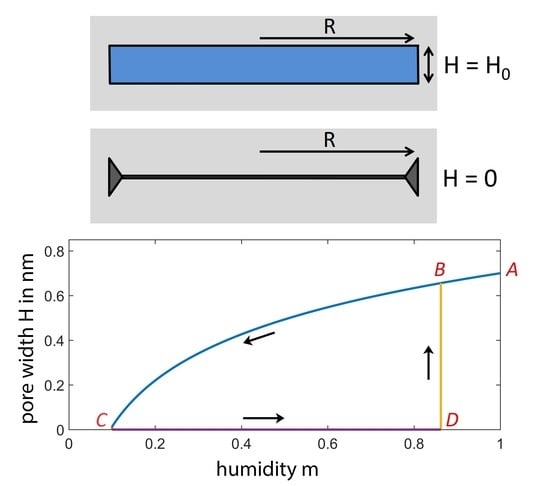
Let us consider a narrow circular slit with radius R and thickness H embedded in a soft solid. The slit is assumed to be completely filled with condensate and connected to the ambient vapor outside the soft solid. This connection (which is not shown in Figure 1) could be a channel between the micropore and an adjacent mesopore, which itself is part of a mesopore system connected to the ambient vapor outside the porous solid. It is useful to introduce the relative vapor pressure where is the vapor pressure of the ambient vapor and the saturation pressure of the bulk fluid. m may vary between a value above the threshold for capillary condensation and one. In this case, a slit pore is either filled with condensate or completely compressed. According to the classical theory of capillarity, the condensate exerts a compressive stress on pore walls, where is the particle number density of the condensate, T the temperature and the Boltzmann constant. As a surprising result, Israelachvili [14] pointed out that this formula for leads to formally correct results for adhesion forces between solid surfaces even at rather low relative vapor pressure (), when the corresponding meniscus radius turns out to be equal to a molecular diameter. In a previous publication [16], we have used the capillary pressure (Kelvin’s equation) to derive the compression of slits in soft materials. In very soft solids, complete slit compression can also occur if its thickness H is relatively large. Hardened cement pastes are not very soft materials. For these porous pastes, length change measurements [17] support the assumption that the thickness of very narrow water-filled slit-like spaces (called interlayer space in the cement literature) and the number of water molecules absorbed in these slits N are directly proportional (). Based on this proportionality, a more general approach leads to a solvation pressure, which is the sum of a humidity-dependent and a humidity-independent term (Appendix A):
The humidity-dependent term:
is proportional to a dimensionless constant factor q, which should not deviate much from one. Here, we always assume that , which leads to the formal coincidence .
If the solid is soft and Young’s modulus E is low, tension is capable of compressing narrow slits. We define as the value of the slit width H at saturation pressure (), which is accompanied by vanishing condensate tension (). When the relative vapor pressure is reduced from to a lower value, the tension can change the pore thickness from to . Reduction of the pore thickness produces elastic deformations in the solid skeleton of the soft solid. The elastic free energy of the deformations resulting from a compressed slit can be approximately evaluated by using the dislocation theory of solids [18,19].
A closed dislocation loop is formally produced by a Volterra process [18,20,21], which is used in the theory of edge dislocations. In the monograph [18], a circular dislocation loop is considered. The production of a circular dislocation loop by a Volterra process is comprised of two steps, where the first step produces the open pore. After the second step, the circular dislocation loop appears at the edge of the former circular slit pore:
Step 1: An open circular slit is produced by removing all atoms of the solid in a disk-like region. The resulting structure appears as a circular slit with a thickness equal to the length b of Burgers vector, which corresponds to an open slit pore with thickness b.
Step 2: The opposite slit walls are pressed together, and the touching slit interfaces are glued. In the physics of solids, chemical bonds bridge both sides of the former slit-like cavity, but we assume that a compressive adhesion force hampers reopening of the pore.
This procedure can also be applied to planar circular slits in amorphous materials, where the slit thickness cannot be identified with the length of a Burgers vector (vector of a crystal lattice) because the elasticity theory is a macroscopic description of matter.
Analogously to the first step of the Volterra process, we can produce the open slit that is shown in the upper part of Figure 1. The slit with thickness and radius R is created by removing all molecules of the disk-shaped region. Then, the slit is filled with water at humidity . The contribution to the solvation force (Equation (1)) is zero for because at saturation pressure (), adhesion appears only in the borderline case (touching surfaces), as we only consider the simplest macroscopic description in this section (a force with a finite range will be considered in Section 2.2). Hence, (Equation (2)) defines the force (per unit area) between separated walls. As , the water-filled cavity retains its thickness , and there are no deformations of the solid skeleton caused by slit compression. For this state (), the elastic free energy should be equal to zero, and the water-filled slit is in mechanical equilibrium (). If humidity m is reduced, the tension compresses the slit. Assuming a Hookean behavior, the elastic free energy (divided by the area ) for the deformed solid is expected to be a quadratic function of the slit wall displacement . The ansatz:
becomes quite plausible if is approximately evaluated by using a Taylor series (Appendix B, Equation (A11)). An approximate expression for can be obtained by using the free energy per slit area resulting from inserting into Equation (3). This completely compressed slit configuration () should appear when the compressive tension is strong enough. On the other hand, the same closed slit configuration appears after the second step of the Volterra process to create a circular edge dislocation loop with for the magnitude of the Burgers vectors (Figure 1). The second step of the Volterra process is equivalent to slit closing. Hence, the elastic free energy for a circular edge dislocation loop is equal to the elastic free energy of a completely compressed slit. Equation for allows us to evaluate an approximate expression for the coefficient in Equation (3). As is demonstrated in the Appendix B, coefficient turns out to be independent of . Thus, we use the notation instead of in the subsequent equations of this paper. Then, the elastic free energy divided by the slit area can be written as:
where (Appendix B, Equation (A15)):
E is Young’s modulus, Poisson’s ratio and radius is comparable to the core radius of the dislocation. For simplicity, we assume that . If the condensate tension is strong enough to completely compress the slit (), we obtain the free energy , which is equal to the elastic free energy of a circular dislocation loop (Figure 1). The closed slit configuration is stabilized by adhesion of the touching slit walls. In previous papers [11,12,13], we have considered the simple macroscopic model for the adhesion potential
where w is equal to the work per unit area to separate two touching planar surfaces at saturation pressure (). The difference of the grand potentials (divided by the slit area A) for the open and the closed slit configuration or can be written as [11]:
The last term is equal to the elastic free energy for . The condition for mechanical stability for open pores () yields:
The potential difference is equal to zero if there is an equilibrium between the open () and the closed pore configuration (). If , the open slit is absolutely stable, and if , the closed configuration is the absolutely stable state.
Let us first briefly discuss the mechanism that leads to sorption hysteresis. Figure 2 illustrates the humidity-dependent width H of a narrow circular slit pore with radius nm. At saturation pressure (), the value of the pore width is chosen to be nm. The slit is embedded in a soft solid with Young’s modulus GPa, Poisson’s ratio and adhesion energy per unit area N/m. The number density of water is nm at the chosen temperature K. The narrow slit is supposed to be always filled with condensate if . However, instead of evaporation, the amount of condensate in the pore can decrease by compression of the pore space. Condensate can be squeezed out of the slit pore, when the compression force (Equation (1)) increases with decreasing humidity m. This process occurs along the desorption branch in Figure 2 (Curve ). According to Equation (8), the slit thickness H is equal to at saturation pressure (), which refers to Point A in Figure 2.
After decreasing m to , the slit is completely closed (Point C), and the onset of the short-range adhesion stabilizes the closed slit configuration (). This configuration remains closed along the line as long as the difference of grand potentials (Equation (7)) is positive. When the humidity m is increased to values exceeding , the potential difference is negative, and the closed slit pore can reopen. We evaluate the threshold for pore reopening from the condition , which refers to the thermodynamic equilibrium between the open and the closed configuration. Thus, the adsorption branch starts at Point C, moves to Point D, jumps to Point B and finally arrives at Point A when m is further increased. The desorption-adsorption cycle () can be repeated many times without serious material damage, since mainly elastic deformations occur. In a region close to the dislocation line, however, the large strain may cause some plastic deformations.
For hardened cement pastes, experimental data for the average distance between adjacent C-S-H sheets (basal spacing) are available, and thus, the relation between m and H can be tested. Let us denote changes of the basal spacing by . Humidity-dependent changes of the slit width H are equal to . According to Equation (8), the change of the basal spacing by varying humidity m should be proportional to . The lower diagram in Figure 2 shows a semi-log plot for illustrating this logarithmic humidity dependence of H. In the plots for experimental data, the absolute vapor pressure is often chosen instead of the relative humidity . Because , this different choice is not important. Using instead of m only causes a uniform shift of data points parallel to the humidity axis in semi-log plots. In Figure 2, the desorption branch A—C appears as a sloped straight line. Furthermore, the absorption branch consists of a straight line C—D parallel to the humidity axis and a perpendicular line D—B describing a discontinuity appearing when the closed slit reopens. This plot can be compared with analogous semi-log plots for experimental data obtained from X-ray measurements. For the branches A—C and C—D, Smith [7] found straight lines as depicted in Figure 2. Some deviations from the linear behavior at high relative humidity along the desorption branch can readily be explained by water-filled mesopores above the threshold of capillary condensation, because the condensed water in mesopores exerts a compression force on the solid skeleton [1,16]. Finally, the experimentally-observed data reveal a rapid change of the basal spacing after pore reopening. The experimental curves are relatively steep, but not perpendicular to the humidity axis, while in Figure 2, the depicted straight line D—B is perpendicular to the humidity axis. This deviation could be explained by a slit size distribution, as illustrated in a previous paper [11].
It should be noted, however, that some publications report on the appearance of jumps along the desorption branch in semi-log plots of the basal spacing versus humidity [15,22]. The macroscopic model that uses the discontinuous adhesion potential (Equation (6)) is not capable of describing a discontinuity of the basal spacing for the desorption branch. In this paper, a more realistic adhesion potential that has a finite interaction range is used. We want to check if this extension is capable of describing a discontinuous dependence of H on m.
2.2. Extended Theoretical Model
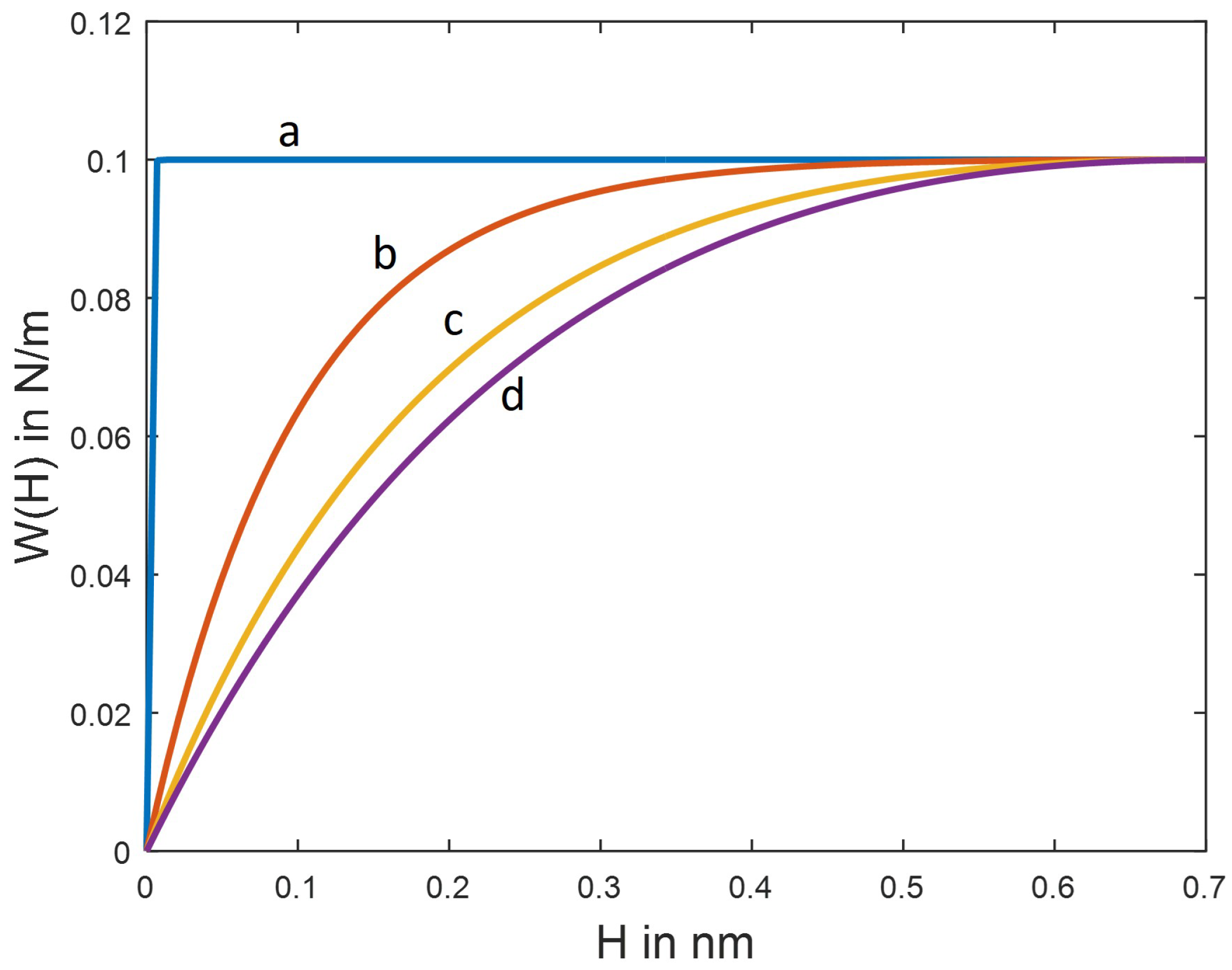
The considered model for the adhesion potential (Equation (6)) is only a proper approximation in cases where the interaction force per unit area decays rapidly with increasing slit wall distance H. For elucidating the impact of a finite interaction range on sorption diagrams, we can use the force:
where the length is a measure of the interaction distance and A is the magnitude of . The choice leads to a compression force accompanied by a cohesion of slit walls. The constants A and in Equation (9) could be fitted to results of Monte Carlo simulations. In hardened cement paste, the cohesion force between C-S-H sheets is supposed to originate from calcium ions in the interlayer water [23]. Equation (7) is replaced by (Appendix A, Equation (A10)):
where is a reference width of the slit at vanishing solvation pressure introduced in the Appendix A. It is expedient to define the reference width as the value of H at vapor saturation (). This width would be equal to if condition were satisfied. Usually, condition is not satisfied because the attraction force between walls is not equal to zero, even at vapor saturation (). Actually, the condition for mechanical stability of an open slit leads to:
At saturation pressure of the vapor, we have , and according to Equation (11), the equilibrium slit thickness deviates from if . It is expedient to introduce a slightly shifted slit thickness by the equation:
It should be noted, however, that the difference between and is rather small, as the force magnitude is a strongly decreasing function of the wall distance H. Thus, the condition holds. Replacing in Equation (10) by using Equation (12), is transformed into:
where an adhesion potential:
is introduced, and is a constant, independent of m. Now, the condition for mechanical stability leads to:
This equation allows us to evaluate how the width H of an open slit depends on the relative vapor pressure m. Obviously, Equation (15) satisfies the condition , and thus, the value of the wall width H at saturation pressure () is equal to . In a similar way, as has been done previously, we define a work per unit area w necessary to separate two touching planar surfaces and to restore the original slit width at saturation pressure (). According to Equation (14), this work can be evaluated by or:
2.3. Mechanical Stability of the Open and the Closed Slit Configuration
In the previous section, we have introduced the difference of grand potentials for deciding whether an open () or closed slit configuration () has a lower grand potential. Checking whether or not has a negative value provides us the preferred state of the slit, but mechanical stability is not guaranteed. Let us first check the stability of the open slit configuration (). Mechanical stability requires that the grand potential as a function of H has a local minimum. Apart from the equilibrium condition , the condition for a local minimum of the grand potential must be satisfied. Hence, taking into account that the grand potential (divided by the constant slit area ) can be written as:
we obtain the stability condition for an open slit
where the width is evaluated by Equation (15). The point on the desorption branch where the open slit configuration loses its stability is the critical point of a fold in the framework of catastrophe theory [24]. At this point, the open pore collapses on the desorption branch, and the closed slit configuration () is the only stable state at low humidity (Figure 4). Unstable branches of the fold catastrophe are not depicted in the diagrams shown in Figure 4. In the borderline case , the extended model for sorption hysteresis based on a continuous function (Equation (18)) reduces to the simpler model with a discontinuous adhesion potential (Equation (6)). Taking into account that and:
for and arbitrary values of n, the stability condition for open pores (Equation (20) turns out to be always satisfied in the case of the discontinuous adhesion model (Equation (6)).
For confirming the consistency of the considered model, we also check the mechanical stability of the closed slit configuration (). Stability considerations for the closed slit state are more subtle because the width H must be always positive (). This constraint for H has the consequence that the condition is not necessary for the closed slit () [24]. Instead, the closed slit configuration is stable if condition holds. From a physical point of view, this condition allows for a compressive stress in the plane bounded by the circular dislocation loop (Figure 1). Using Equation (19), condition yields:
Obviously, for sufficiently small values of the interaction length , the condition for local stability (Equation (22)) of closed slits is satisfied in the whole range of relative vapor pressure (or relative humidity) . Using the stability conditions (Equations (20) and (22)), the mechanical stability of all states defined by the isotherms illustrated in this paper can also be checked.
3. Results and Discussion
Sorption hysteresis at moderate and low humidity can be explained by strong cohesion forces, which attract the walls of narrow slit pores [11,12,13]. The presented model suggests a possible mechanism, which leads to a sorption hysteresis loop accompanied by a related loop of the pore volume change. Low pressure hysteresis can be based on pore closing by compressive stress (solvation force) and a stabilization of the closed pore configuration by short-range adhesion. In previous papers [11,12,13], we have used a primitive discontinuous adhesion potential, which is zero if slit walls are touching each other and jumps to a constant non-zero value if the slit is open and the walls are separated from each other. For moderately rigid materials with slit pores, such as hardened cement paste, this simple model leads to a very low humidity threshold necessary for pore closing, which is a precondition for the appearance of large hysteresis loops. However, experimentally-observed sorption isotherms for hardened cement paste show large hysteresis loops even in those cases where the humidity is not very small [3]. Thus, the considered simple model for sorption hysteresis seems to be not applicable to porous materials that are not very soft. This disadvantage of the sorption model can be remedied by introducing a smooth adhesion potential, which produces a compression force between separated slit walls and supports pore closing. As an example, we have used an exponentially-decaying adhesion potential, which is suitable to define an interaction length . If tends to zero, the extended model with continuous adhesion potential reduces to the simple model with discontinuous adhesion potential. Figure 4 shows sorption isotherms with the hysteresis loop for four different interaction lengths . The first diagram (a) depicts the case of a very low value for the interaction length ( nm). In this case, isotherms evaluated by the continuous and the discontinuous adhesion model are indistinguishable. The slit wall distance H (and thus, the adsorbate volume) is a monotone continuous function of the relative humidity m (Figure 4a). However, if is distinctly larger than zero, the slit width H jumps from a finite value to zero on the desorption branch. As shown in Diagrams b, c and d, the humidity threshold for pore closing, where H jumps from a finite value to zero on the desorption branch, strongly increases with increasing . In contrast to the threshold for slit closing on the desorption branch, the humidity threshold for pore reopening on the adsorption branch is almost constant if increases. Obviously, the more general continuous adhesion model can lead to pore closing at a much higher relative vapor pressure than the discontinuous model. A smoothly-varying adhesion potential avoids extraordinarily small values of relative vapor pressure required for slit pore closing. Therefore, we expect that extended models with a smooth adhesion potential are capable of providing us a better description of the sorption hysteresis for porous solids if they are not very soft.
Tests of the model can be done by comparing theoretical results with available experimental results for hardened cement pastes. Some theoretical and experimental sorption isotherms have been compared in a previous publication [11]. The comparison of sorption isotherms is difficult because hardened cement pastes have a complex pore structure. Apart from micropores, the pastes also have mesopores, which contain a large amount of water at high humidity m. Thus, analyzing the humidity dependence of the basal spacing may provide us a better interpretation, since X-ray experiments only probe micropores. The basal spacing changes due to humidity-dependent absorption and desorption of water layers between the C-S-H sheets. The change of the basal spacing is equal to the change of the slit width H. According to Equation (8), the change of the basal spacing should obey a logarithmic law () on the desorption branch, as shown in the lower diagram of Figure 2. This logarithmic dependence is confirmed by semi-log plots of experimental data by Smith [7]. In other presumably differently-prepared hardened cement pastes, the change of the basal spacing is discontinuous at a certain water vapor pressure [15]. Our extended model allows us to describe such a jump in the desorption branch, as illustrated in Figure 4. However, more experimental data are needed for a comprehensive test of the simple mesoscopic model.
Author Contributions
Conceptualization, P.S.; Methodology, P.S.; Software, M.W.; Validation, M.W.; Writing—Original Draft Preparation, P.S.; Writing—Review and Editing, M.W., T.A.B. and H.-J.M.; Visualization, M.W.; Supervision, H.-J.M.; Project Administration, H.-J.M.; Funding Acquisition, T.A.B. and H.-J.M.
Funding
Financial support by the German Research Foundation DFG (Grant MO 600/9-2) is gratefully acknowledged.
Conflicts of Interest
The authors declare no conflict of interest.
Appendix A. Grand Potential of a Slit Filled with Condensate in a Non-Rigid Solid
The thermodynamics of a fluid phase condensed in a narrow slit-shaped pore can be described by using the grand potential , where F is the free energy of the condensate, N the number of absorbed molecules in the slit and the chemical potential of a molecule. Assuming thermodynamic equilibrium between the condensed vapor and the abundant vapor outside the slit, the differential can be written as [25,26]:
where S is the entropy, T the temperature, the bulk phase pressure (vapor), the solid-fluid interfacial tension, the pressure exerted on the pore walls by the condensate (solvation pressure), H the pore width and A the surface area of one of the pore walls. We only consider the case of large solvation pressures, i.e., is large compared to (). Obviously, if the pore width H decreases with increasing magnitude of pressure , the slit area A remains constant. Thus, keeping temperature T constant, Equation (A1) is simplified to:
Using Equation (A1), Gelb et al. [25] and Balbuena et al. [26] did not account for the elastic deformations of the solid skeleton if the slit were compressed from an initial thickness to a lower thickness H. Assuming Hooke’s law for the stress-strain relationship, the contribution of elastic restoring forces to the differential of the grand potential can be written as , where coefficient depends on the pore radius R in the case of a circular slit pore. In this paper, is defined as the slit thickness at vanishing solvation pressure (). An approximate evaluation of is possible by applying the dislocation theory [18,19] for solids. If other materials with narrow slit pores such as montmorillonite clay are considered as smectic liquid crystals, the dislocation theory of smectics should be used to evaluate [20,21]. Hence, differential of the grand potential for a slit filled with condensate is expressed as
Applying Maxwell’s rule to the exact differential (A3) and taking into account that is independent of yield:
In the case of a macroscopic slit with thickness H, which is much larger than the diameter of a condensate molecule, the relation is satisfied, where is the number density of the bulk liquid. For hardened cement pastes, plots of length change data versus the absorbed amount suggest that N is directly proportional to H with a proportionality constant that is independent of the chemical potential [11]. However, if the slit thickness H is comparable to one or a few diameters of a condensate molecule, the proportionality coefficient in the linear relation between N and H is not necessarily equal to , as in the case of a thick slit. Thus, we use a slightly generalized relation , where q is a dimensionless constant, which is not much different from one. Then, the relation results, and Equation (A4) yields:
Integration of Equation (A5) leads to:
where the function does not depend on the chemical potential and the relative vapor pressure m. There is a thermodynamic equilibrium between water condensed in slit pores and the ambient water vapor outside the porous material (). Thus, if the vapor is considered as a perfect gas, the chemical potential of a condensed water molecule can be written as , where is a function of the temperature and the vapor pressure. Introducing the saturation pressure , the relative vapor pressure is defined by , and the chemical potential may be rewritten as:
where denotes the chemical potential of the molecules in saturated vapor (), the Boltzmann constant and T the temperature. Inserting Equation (A7) into Equation (A6) leads to the solvation pressure:
where the humidity-dependent contribution is defined as:
In the case of thick slits, the value of q is equal to one, and coincides with the capillary force used in the classical theory of capillarity. Parameter q could be adjusted by fitting experimental data for the desorption branch in a semi-log plot of H versus m (lower diagram in Figure 2). In this paper, we always assume that . The function can be identified with the short-range adhesion force between the walls of the filled slits. Finally, let us derive an expression for the grand potential by a direct integration of Equation (A3) over H at constant (or m). This integration:
yields:
where Equation (A8) is used. The reference grand potential ( for the lower integration limit) only comprises elastic free energy of the solid skeleton and is independent of and m, since the closed slit does not contain any condensate ( and ). In Section 2.2, the slit thickness (formally defined for ) is replaced by the thickness , which is the value of H for (vapor saturation).
Appendix B. Evaluation of the Elastic Free Energy
Coefficient in the elastic free energy contribution to the grand potential (Equation (A10)) is derived by using the dislocation theory. We consider a circular slit with radius R in an isotropic elastic solid. The elastic free energy of the solid skeleton depends on the width H and the radius R of the slit. At vanishing solvation force, if were equal to zero, the slit thickness H would be equal to the reference value . A slit can be compressed by the solvation tension exerted on the slit walls. The elastic free energy of the solid depends on the deviation of the slit width H from its reference value at . Hook’s law in elasticity theory suggests that a Taylor series of up to second order terms should be an accurate approximation. Thus, we obtain:
where and the Landau symbol indicates that higher order terms are neglected. In the reference state for , the elastic free energy must have its minimum value (mechanical equilibrium). Hence, condition is satisfied, and thus, Equation (A11) can be simplified to:
where we have omitted the constant term . Coefficient could be considered as an empirical quantity that must be fitted to experiments. An approximate expression for can be obtained from the dislocation theory. A strong solvation force may squeeze out the water of a narrow slit, so that its thickness H becomes zero. As discussed in Section 2.1, the completely compressed slit pore () in the solid material can be considered as a circular edge dislocation loop with Burgers vector satisfying the relation . According to Hull [18] (Chapter 5, Equation (5.10)), an approximate expression for the elastic free energy of a circular edge dislocation loop is given by:
where G denotes the shear modulus and is a fixed radius comparable to the core radius of the dislocation. This formula was also published in a monograph on rheophysics [19]. Taking into account the relation between Young’s modulus and shear modulus, the elastic free energy per loop area is written as:
Now, the unknown coefficient in the elastic free energy can be adjusted by comparing (closed slit, ) and (circular edge dislocation with magnitude of the Burgers vector). If and , equation leads to a function , which does not depend on :
Finally, we note that Equation (A15) for coefficient is not changed if Equation (12) is used to replace by (reference slit width for humidity instead of for vanishing solvation tension ). In the case of the macroscopic description of adhesion (Section 2.1), the humidity-independent part of the solvation force is non-zero only if (completely closed slit). Then, Equation (12) leads to and rather simple equations (Equations (4), (7) and (8)) in Section 2.1.
References
- Amberg, C.H.; McIntosh, R.A. Study of absorption hysteresis by means of length changes of a rod of porous glass. Can. J. Chem. 1952, 30, 1012–1032. [Google Scholar] [CrossRef]
- Sing, K.S.W.; Everett, D.H.; Haul, R.A.W.; Moscou, L.; Pierotti, R.A.; Rouquerol, J.; Siemieniewska, T. Reporting Physisorption Data for Gas/Solid Systems with Special Reference to the Determination of Surface Area and Porosity. Pure Appl. Chem. 1985, 57, 603–619. [Google Scholar] [CrossRef]
- Jennings, H.M.; Kumar, A.; Sat, G. Quantitative discrimination of the nano-pore-structure of cement paste during drying: New insights from water sorption isotherms. Cem. Concr. Res. 2015, 76, 27–36. [Google Scholar] [CrossRef] [Green Version]
- Barrer, R.M.; MacLeod, D.M. Intercalation and Sorption by Montmorillonite. Trans. Faraday Soc. 1954, 50, 980–989. [Google Scholar] [CrossRef]
- Feldman, R.F.; Sereda, P.J. A model for hydrated Portland cement paste as deduced from sorption-length change. Mater. Struct. 1968, 1, 509–520. [Google Scholar] [CrossRef]
- Feldman, R.F.; Sereda, P.J. A new model for hydrated Portland cement and its practical implications. Eng. J. Can. 1970, 53, 1–7. [Google Scholar]
- Smith, R.H. Basal Spacing Hysteresis in CSH(1). Cem. Concr. Res. 1973, 3, 829–832. [Google Scholar] [CrossRef]
- Pinson, M.B.; Masoero, E.; Bonnaud, P.A.; Manzano, H.; Ji, Q.; Yip, S.; Thomas, J.J.; Bazant, M.Z.; Van Vliet, K.J.; Jennings, H.M. Hysteresis from multiscale porosity: Modeling water sorption and shrinkage in cement paste. Phys. Rev. Appl. 2015, 3, 064009-1–064009-17. [Google Scholar] [CrossRef]
- Muller, A.C.A.; Scrivener, K.L.; Gajewicz, A.M.; McDonald, P.J. Use of bench-top NMR to measure the density, composition and desorption isotherm of C-S-H in cement paste. Microporous Mesoporous Mater. 2013, 178, 99–103. [Google Scholar] [CrossRef]
- Gutteridge, W.A.; Parrott, L.J. A Study of the Change in Weight, Length and Interplanar Spacing Induced by Drying and Rewetting Synthetic CSH (I). Cem. Conr. Res. 1976, 6, 357–366. [Google Scholar] [CrossRef]
- Schiller, P.; Wahab, M.; Waida, S.; Bier, T.; Mögel, H.-J. Dislocation model for sorption hysteresis in deformable solids. Colloids Surf. A Physicochem. Eng. Aspects 2017, 513, 76–86. [Google Scholar] [CrossRef]
- Schiller, P.; Wahab, M.; Bier, T.; Waida, S.; Mögel, H.-J. Sorption hysteresis of hardened cement pastes. MSCE 2016, 4, 40–48. [Google Scholar] [CrossRef]
- Schiller, P.; Wahab, M.; Bier, T.; Waida, S.; Mögel, H.-J. Capillary forces and sorption hysteresis of cement pastes with small slit pores. Proc. Mater. Sci. 2015, 11, 649–654. [Google Scholar] [CrossRef]
- Israelachvili, J.N. Intermolecular and Surface Forces; Academic Press: Amsterdam, The Netherlands, 2011; ISBN 978-012391927-4. [Google Scholar]
- Smith, R.H.; Bayliss, P. Interlayer Desorption of CSH(1). Cem. Concr. Res. 1972, 2, 643–646. [Google Scholar] [CrossRef]
- Schiller, P.; Bier, T.; Wahab, M.; Mögel, H.-J. Mesoscopic model of volume changes due to moisture variations in porous materials. Colloids Surf. A Physicochem. Eng. Aspects 2008, 327, 34–43. [Google Scholar] [CrossRef]
- Duckheim, C.; Setzer, M.J. Drying shrinkage of hardened cement paste. In Creep, Shrinkage and Durability Mechanics in Concrete and Concrete Structures, Proceedings of the Eighth International Conference on Creep, Shrinkage and Durability of Concrete and Concrete Structures, Ise-Shima, Japan, 30 September–2 October 2008; Tanabe, T., Sakata, K., Mihashi, H., Sato, R., Maekawa, K., Nakamura, H., Eds.; CRC Press: Boca Raton, FL, USA, 2008; pp. 49–55. ISBN 978-041548508-1. [Google Scholar]
- Hull, D.; Bacon, D.J. Introduction to Dislocations, 5th ed.; Butterworth-Heinemann: Oxford, UK, 2011; Chapter 5.5; ISBN 978-008096672-4. [Google Scholar]
- Oswald, P. Rheophysics: The Deformation and Flow of Matter; Cambridge University Press: Cambridge, UK, 2009; Chapter 5.1; ISBN 978-052188362-7. [Google Scholar]
- Kleman, M.; Lavrentovich, O.D. Soft Matter Physics: An Introduction; Springer: New York, NY, USA, 2003; Chapter 8; ISBN 978-144192927-3. [Google Scholar]
- Chaikin, P.M.; Lubensky, T.C. Principle of Condensed Matter Physics; Cambridge University Press: Cambridge, UK, 1995; Chapter 9; ISBN 978-052143224-5. [Google Scholar]
- Bayliss, P. Further Interlayer Desorption Studies of CSH(1). Cem. Concr. Res. 1973, 3, 185–188. [Google Scholar] [CrossRef]
- Bonnaud, P.A.; Ji, Q.; Coasne, B.; Pellenq, R.J.-M.; Van Vliet, K.J. Thermodynamics of Water Confined in Porous Calcium-Silicate-Hydrates. Langmuir 2012, 28, 11422–11432. [Google Scholar] [CrossRef] [PubMed]
- Gilmore, R. Catastrophe Theory for Scientists and Engineers; Dover Publications: New York, NY, USA, 1993; ISBN 978-0-48-667539-8. [Google Scholar]
- Gelb, L.D.; Gubbins, K.E.; Radhakrishnan, R.; Sliwinska-Bartkowiak, M. Phase separation in confined systems. Rep. Prog. Phys. 1999, 62, 1573–1659. [Google Scholar] [CrossRef]
- Balbuena, P.B.; Berry, D.; Gubbins, K.E. Solvation Pressure for Simple Fluids in Micropores. J. Phys. Chem. 1993, 97, 937–943. [Google Scholar] [CrossRef]
Figure 1.
Cross-section of a narrow circular slit pore with radius R and width is embedded in a soft solid filled with condensate at saturation pressure (). At low values of m, the slit is completely compressed () and degenerates to a closed dislocation loop. The dark triangles symbolize the cross-section of the dislocation core, where the solid material is strongly compressed. Connections to larger pores or to the ambient vapor outside the porous solid are not depicted.

Figure 2.
Thickness of a circular slit filled with water ( nm, nm) embedded in a soft solid ( GPa, , N/m, K) evaluated by using Equation (8).
Figure 2.
Thickness of a circular slit filled with water ( nm, nm) embedded in a soft solid ( GPa, , N/m, K) evaluated by using Equation (8).

Figure 3.
Adhesion potential with magnitude N/m versus the slit width H dependent on the interaction length : (a) nm, (b) nm, (c) nm and (d) nm.
Figure 3.
Adhesion potential with magnitude N/m versus the slit width H dependent on the interaction length : (a) nm, (b) nm, (c) nm and (d) nm.

Figure 4.
Thickness of a circular slit filled with water ( nm, nm) embedded in a soft solid ( GPa, , N/m, K) evaluated by using Equation (15). The interaction length is different: (a) nm, (b) nm, (c) nm and (d) nm.
Figure 4.
Thickness of a circular slit filled with water ( nm, nm) embedded in a soft solid ( GPa, , N/m, K) evaluated by using Equation (15). The interaction length is different: (a) nm, (b) nm, (c) nm and (d) nm.

© 2018 by the authors. Licensee MDPI, Basel, Switzerland. This article is an open access article distributed under the terms and conditions of the Creative Commons Attribution (CC BY) license (http://creativecommons.org/licenses/by/4.0/).
Share and Cite
MDPI and ACS Style
Schiller, P.; Wahab, M.; Bier, T.A.; Mögel, H.-J. Low Pressure Hysteresis in Materials with Narrow Slit Pores. Colloids Interfaces 2018, 2, 62. https://doi.org/10.3390/colloids2040062
AMA Style
Schiller P, Wahab M, Bier TA, Mögel H-J. Low Pressure Hysteresis in Materials with Narrow Slit Pores. Colloids and Interfaces. 2018; 2(4):62. https://doi.org/10.3390/colloids2040062
Chicago/Turabian StyleSchiller, Peter, Mirco Wahab, Thomas A. Bier, and Hans-Jörg Mögel. 2018. "Low Pressure Hysteresis in Materials with Narrow Slit Pores" Colloids and Interfaces 2, no. 4: 62. https://doi.org/10.3390/colloids2040062