

Drop Impact onto a Substrate Wetted by Another Liquid: Flow in the Wall Film


Institute for Fluid Mechanics and Aerodynamics, Technical University of Darmstadt, 64287 Darmstadt, Germany
*
Author to whom correspondence should be addressed.
Colloids Interfaces 2022, 6(4), 58; https://doi.org/10.3390/colloids6040058
Submission received: 19 September 2022
/
Revised: 11 October 2022
/
Accepted: 12 October 2022
/
Published: 20 October 2022
(This article belongs to the Special Issue Exclusive Papers of the Editorial Board Members of Colloids and Interfaces 2022)
Abstract
:The impact of a drop onto a liquid film is relevant for many natural phenomena and industrial applications such as spray painting, inkjet printing, agricultural sprays, or spray cooling. In particular, the height of liquid remaining on the substrate after impact is of special interest for painting and coating but also for applications involving heat transfer from the wall. While much progress has been made in explaining the hydrodynamics of drop impact onto a liquid film of the same liquid, the physics of drop impact onto a wall film with different material properties is still not well understood. In this study, drop impact onto a very thin liquid film of another liquid is investigated. The thickness of the film remaining on a substrate after drop impact is measured using a chromatic-confocal line sensor. It is interesting that the residual film thickness does not depend on the initial thickness of the wall film, but strongly depends on its viscosity. A theoretical model for the flow in the drop and wall film is developed which accounts for the development of viscous boundary layers in both liquids. The theoretical predictions agree well with the experimental data.
1. Introduction
The high relevance of the impact of single drops onto wetted walls for a large number of industrial and technical applications has been repeatedly highlighted in related reviews [1,2,3]. These applications include spray painting, spray cooling, ink-jet printing agricultural sprays and many more. In particular, the situation when droplets and film liquid differ lacks a detailed description in the literature but is of high relevance for many technical applications. For instance in catalytic exhaust gas after-treatment systems, where a spray of urea-water solution impinges onto a wall film, which has, due to evaporation and temperature gradient, different fluid properties than the impinging spray droplets [4]. A further example is the situation in an internal combustion engine, where fuel droplets may impinge on the piston and cylinder walls, which are wetted by oil. This can lead to the formation of deposits and secondary droplets, which can change the process parameters and eventually lead to pre-ignition [5]. In spray cooling applications the height of the liquid layer remaining on the substrate is of special interest for modelling the heat flux through the wall [6]. In this application, the wall film may have different fluid properties than the drops of the spray due to the temperature gradient.
Comprehensive reviews [1,2,3,7,8] describe the hydrodynamics of the impact of a drop onto solid substrates as well as thin liquids films and suggest models for their description. The drop impact is influenced by both the liquid properties such as surface tension , viscosity , density , and the impact parameters which are the drop diameter D, the liquid film height before impact and the impact velocity of the drop U. Those quantities can be summarized into the following dimensionless groups:
The subscripts d and f denote that the property either corresponds to the drop or the film liquid.
Drop impacting onto a solid dry or wetted substrate generates a radially expanding flow in a thin lamella. A remote asymptotic solution for the flow in the lamella, valid for times , is obtained in [9]
where is the dimensionless radial velocity in the lamella, is the dimensionless uniform lamella thickness, and and are dimensionless constants determined from experiments. This solution satisfies the mass and momentum balance equations for inviscid flow. All the length variables are scaled by the initial drop diameter D, velocities are scaled by the impact velocity U and time is scaled by the characteristic time . The linear profile of the radial velocity (2) has been confirmed in [10,11] using particle velocimetry inside the spreading drop.
Certainly, the expression for the velocity distribution (2) is not valid for the initial stage of drop impact . In the phase of the initial drop deformation, a vortex pattern has been observed [12] which can influence the flow in the lamella at large times.
A general solution for the evolution of the lamella thickness, valid for long times, is obtained in [13] in the form
The values of and are obtained from the CFD computations of drop impact onto a dry substrate with and .
Solutions (2) and (3) are valid only for an interval when the lamella thickness is larger than the thickness of the viscous boundary layer expanding near the wall. In [14] an analytical solution of the Navier-Stokes equations for a thin spreading viscous film is obtained. The expression for the lamella thickness which accounts for the viscous effects is
where is the instant at which the thicknesses of the lamella and of the viscous boundary layer are equal. The value of the coefficient is predicted theoretically in [14] from the solution for drop impact onto a smooth planar dry substrate.
At times the dynamics of the lamella are governed by the balance of the inertial and viscous terms. At large times the lamella thickness approaches an asymptotic value
the thickness of the residual film after impact. The theoretical prediction for agrees very well with the experimental data [15] obtained for drop impact onto a spherical target.
Furthermore, the measurements of the evolution of the lamella at the impact axis [16] found that the residual film thickness resulting from the impact of a drop onto a liquid film of finite thickness can be described as:
where A is a dimensionless constant depending on the initial dimensionless film thickness . The value of A approaches the solution for drop impact onto a dry substrate for relatively thin wall films, . For drop impact onto wetted substrates with a wall film thickness in the range of , a uniform asymptotic film thickness that fills between 64% and 85% of the maximum cavity radius is observed in [17].
If the Reynolds and Weber numbers are high enough the impact leads to the generation of a crone-like liquid jet. This jet is described in [9] as a kinematic discontinuity, resulting from the interaction of the flow in the expanding lamella and the outer wall film. The propagation of the base of the corona of radius is governed mainly by inertia at the early stages of crown propagation. The expression for is obtained in [9] in the form
where is a dimensionless coefficient. This expression agrees well with the experimental observations for relatively small times. The expression can be modified by taking capillary and gravity effects [18]
where is Froude number. Expression (8) predicts corona expansion and its receding. The empirical relations for the dimensionless parameters and are obtained in [18]
Recently, a model for the corona propagation that takes viscous losses into account was proposed by [19]. It shows a good agreement to experimental data, even for large times of corona propagation. The expression for is obtained as
whereby is a dimensionless constant, is a time-dependent function incorporating viscous losses, incorporates the losses at the initial stage of the impact phase and , as well as are the starting values of a fully formed corona.
The next important parameter characterizing the outcome of drop impact is the splashing threshold associated with the minimum impact velocity which leads to the generation of secondary drops. The empirical relation for the splashing threshold [20,21] for drops impacting onto a wetted wall is given in the form
Different variants of the empirical correlations of the splashing threshold can be found in several experimental studies [22,23,24,25,26,27,28]. In an experimental and theoretical study [29] a model for splashing threshold on stationary and flowing wall liquid film is developed based on an energy balance approach.
Recently, the expression for the splashing threshold has been generalized for cases when liquid drop impacts onto a substrate wetted by another liquid. The corresponding models for splashing threshold are often formulated in the form of a modified critical K number which depends on the viscosity ratio of the wall film and drop liquids [30,31].
It is interesting that the wall film thickness influences also the dynamics of the air layer between the film and the spreading drop. At relatively small Weber numbers such gas layer can prevent coalescence and lead to the bouncing, complete drop rebound from the wetted wall [32].
In this experimental and theoretical study, the two-component as well as one-component drop impact is investigated. The thickness of the film remaining on a substrate after a drop impact is measured for a broad range of impact parameters. Then, the dynamics of drop spreading and the influence of the viscosity of the wall film are considered.
2. Experimental Setup
The experimental setup is represented schematically in Figure 1. The setup can be divided into the main groups: drop generation system, optical system, film thickness measurement system, as well as the impact substrate. A drop is generated by pumping liquid through the micro-pump into a needle, at the tip of which a drop is formed. As soon as this drop reaches a critical mass, it drips off and falls, accelerated by gravity. The impact velocity can be varied by adjusting the height of the needle above the substrate. A high-speed CMOS camera (Photron SA-X2) is used in combination with a high performance LED (Veritas Constellation 120E) in the optical system to capture the high dynamics of drop impact. A diffusor plate is placed in front of the LED to guarantee uniform illumination. The camera operates with frame rates in a range from 20 to 50 kHz. The impact substrate consists of an optically transparent sapphire plate with a diameter of 50 mm and a height of 0.5 mm. A liquid film is applied on top of the sapphire plate and confined either by pinning on the sapphire edge or by PVC foil.
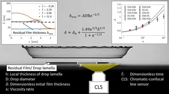
The height of the film on the substrate is determined using a chromatic-confocal line sensor (Precitec Chrocodile, short: CLS) in combination with a CLS 0.5 LL probe. This system can determine the film thickness on a line of 4.5 mm length with a rate of 2 kHz at high accuracy of m. It allows for precise measurement of the film thickness before the drop impact while also providing spatial and time-resolved film thickness information during and after drop impact. The CLS and the high-speed camera are synchronized by use of a NI-DAQ system in combination with an in-house LabView code. Since in this study miscible liquids with the same refractive index of n = 1.402 are investigated, no detectable interface forms between drop and film, thus the measured film thickness after impact is the total thickness of both, drop and film liquid combined. The properties of the liquids used in this study are summarized in Table 1.
3. Residual Film Thickness
In Figure 2 the impact of a silicone oil (S10) drop onto a silicone oil film (S10), captured by the high-speed video system, is shown in three consecutive instants before, during, and after the impact. The time is given in dimensionless form . It can be observed that the drop impact results in the formation of a crown ( = 1.92) which subsequently fragments into secondary droplets ().
Simultaneously, flow in the wall film is characterized using the CLS. The yellow line in Figure 2 indicates the position of the measuring line of the CLS whereat the x represents the longitudinal coordinate. The film thickness h above the substrate as a function of the longitudinal coordinate x is shown in Figure 3 for different times. The instants shown in this graph correspond to the high-speed recordings shown in Figure 2.
The blue curve in Figure 3 shows the undisturbed film of uniform thickness m prior to the drop impact. At a crown has formed as a result of the drop impact. The base of the crown can be recognized at the discontinuity of the orange graph at mm. For larger times , the lamella height reaches an asymptotic value and forms a disk of nearly uniform height with a rim at its edge. Even for very large times the thickness of the film remaining on the substrate does not change and thus is referred to as residual film thickness .
The measurement results for the evolution in time of the film thickness at the impact axis are shown in Figure 4. The impact axis is not exactly at the position of the CLS for every impact. The approximate impact axis is determined by using the local maximum of the drop lamella at early times. For the example, shown in Figure 3, this would result in mm, taking the film thickness distribution at as a reference. The measured values m at the impact instant ms, correspond to the stage when the total film thickness, including the drop height, exceeds the maximum limit of the working range of the instrument. The evolution of the film thickness in time is only very slightly influenced by the initial film thickness, as shown in Figure 4a. However, Figure 4b,c reveal that the dependence of the drop viscosity and even the wall film viscosity is significant.
In all the cases, shown in Figure 4 the evolution of the film thickness initially follows the inertial regime expressed in Equation (2). At later times, at 2–3 ms, when the thickness is comparable with the thickness of the viscous boundary layer the viscous effects become dominant. As a result, a constant residual thickness is measured. The thickness of the residual film after drop impact onto a dry substrate is determined in Equation (5) and after drop impact onto a substrate wetted by the same liquid of the initial thickness comparable with the drop diameter, is expressed in Equation (6). A detailed analysis and the predictive model are described in the next section.
In Figure 5 the relation of the residual film height to the initial film thickness is shown. The residual film height is de-dimensionalised by D and scaled by . With this scaling, the ordinate represents the factor A defined in Equation (6). The impact parameters of the experiments are listed in Table 2. In cases 1 to 7 the drop and film liquid, do not differ in the individual experiments. The viscosity, drop diameter and impact velocity are varied. It becomes apparent that none of these parameters influences the scaling, thus all values collapse on a horizontal line at . It is worth to be mentioned that this value is close to the theoretical predictions of for drop impact onto dry substrates [14]. Furthermore, it can be seen, that the initial film thickness has almost no effect on the scaling, neither for the one-component impact of cases 1 to 7, nor the two-component impact presented in cases 8 and 9. This result confirms the conclusions of [16]. Only when the liquid of the film and drop differ as in cases 8 and 9, where the viscosity ratio of film to drop viscosity is and , the scaling changes. This is a rather surprising result, noting that the residual film thickness itself seems to be independent on the initial film height and the initial film height is much smaller than the drop diameter. How does the viscosity of the wall film influence the dynamics of drop spreading and thus the residual film height while it is independent of the initial film thickness?
4. Dynamics of the Drop and Wall Film Spreading
Consider an impact of a liquid drop onto a solid substrate wetted by another liquid. If the Reynolds and Weber numbers are much higher than unity the impact is governed by liquid inertia. Although the investigated liquids in the experiments are miscible, the effects of diffusion are neglected since they occur on a much larger time scale. This is justified due to the fact, that that the diffusion coefficient, which is reported to be in the order of to m/s and is much lower than the kinematic viscosity of m/s [33,34]. The interface between the two liquids is therefore theoretically treated as if the liquids were immiscible. The initial deformation of an inviscid drop onto a solid substrate is considered in [35]. The flow is approximated by a flow past a disc of a wetted radius , which is defined in Figure 6a. In the case of drop impact onto a liquid film the interfacial velocity at the film-drop interface, indicated in Figure 6a, has to be considered. The pressure at the interface at the initial stage of impact can be estimated as [35]
If the contact radius is much smaller than the thickness of the wall film, the pressure in the film can be estimated from [35], using a similar approach
Equating both these pressure expressions and taking only the dominant term for short times yields
Certainly, if the densities of the liquids are very close, Expression (16) is reduced to
This relation has been identified in the experimental studies on drop impact onto a liquid layer of the same liquid [36,37,38]. However, the explanation of this relation is based on the pressure estimation using the stationary Bernoulli equation which neglects transient effects.
If the initial thickness of the wall film is much smaller than the drop diameter, (as in the present experiments), the duration of the initial drop penetration with the velocity is very short, , and its influence on the flow in the subsequent stages of impact can be neglected.
At larger times when the spreading radius is larger than the drop height the flow in the drop and in the lamella can be approximated by an inviscid thin film flow [9], taking into account a growing viscous boundary layer that is restrained first to the wall film on the substrate, as indicated in Figure 6b [14].
4.1. Short Times after Impact: Boundary Layer in the Wall Film
If the Reynolds number of the impacting drop is much higher than unity, the spreading of the lamella is dominated by inertia. In the case of a dry wall the evolution of the lamella thickness is expressed in (4) if it is thicker than the viscous boundary layer. We can expect that these expressions are valid also for the case of drop impact onto a substrate wetted by the same liquid, if the film thickness is much smaller than the drop initial diameter, as shown schematically in Figure 6b.
The evolution of the thickness of the wall film for long times can be estimated using the same approach as in the case of the drop lamella
where is the ratio of the drop and film viscosities, and is the Reynolds number based on the drop viscosity, defined in (1). Expression (18) is obtained using the viscosity of the wall film in the solution from [13] and accounting for the initial dimensionless film thickness .
Next, the modified solution [13] can be used for the estimation of the characteristic times and thicknesses. The time at which the wall film thickness is equal to the thickness is therefore
The corresponding wall film thickness at this instant is
At times the flow in the wall film is driven mainly by viscous stresses.
4.2. Long Times: Boundary Layer of the Spreading Drop
At long times after impact the thickness of the viscous boundary layer is much larger than the thickness of the wall film. The flow has to satisfy the continuity of the velocity and the shear stress at the film/drop interface at the distance from the wall. The similarity solution [14] is not valid in this stage. The approximate solution in this stage consists of the outer solution in the drop lamella and the inner solution in the wall film, as shown in the sketch in Figure 6c,d.
4.2.1. Outer Solution in the Lamella of the Spreading Drop
The thickness of the wall film is much smaller than the thickness of the viscous boundary layer in the liquid drop. In the outer solution, shown schematically in Figure 6c, the thickness of the wall film is therefore neglected, the velocity profile and the shear stresses are approximated by the solution for drop impact onto a solid substrate [14]. This approximation is justified by the fact that the velocity at the interface is much smaller than the velocity of the inviscid flow outside the boundary layer.
The thickness of the viscous boundary layer in the lamella of the drop can be approximated as . The radial velocity far from the interface at large times is estimated using Expression (2). The shear stress at the wall in the liquid is estimated in [14] as
At large times we can assume, that the velocity in a thin liquid wall film is much smaller than the velocity of spreading outside the boundary layer. Therefore, Expression (22) is valid also for the case of drop spreading on a thin wall film at large times .
4.2.2. Inner Solution for the Wall Film
The flow in the thin wall film is approximated by a linear profile, as shown in Figure 6d. This flow can be estimated from the condition of the continuity of the shear stress at the interface with the drop flow
The axial velocity in the wall film interface is then found from the continuity equation using (22) and (23)
The velocity W determines the rate of change of the wall film thickness. The evolution equation for at long times is therefore
The solution of the ordinary differential Equation (25) which satisfies the initial condition is
For large times the wall film thickness approaches the residual value
Finally, the residual film thickness is estimated as the sum of the residual thicknesses of the wall film and drop lamella
where is a weak function of the film thickness, assumed constant for . The value is taken from the results [14] obtained for drop impact onto a dry wall. The estimated value of for a dry substrate is . However, it can be different in the case of drop impact onto a wetted wall since the drop spreading can be influenced by the initial stage of drop collision with the wall film.
In most practical cases the density ratio of the wall film and drop liquids is rather close to the unity. The expression for the parameter A can be thus reduced to
In Figure 7 The experimental data for the factor A are compared with the theoretical predictions (30) based on and , the smallest and the largest relative film thicknesses, used in these experiments. The theoretical predictions only weakly depend on the initial film thickness but rather significantly depends on the viscosity ratio . The value is estimated from the best fit to the experimental data. The theoretical predictions agree rather well for values of .
At larger values of , associated with the viscosity of the film liquid exceeding significantly the viscosity of the drop liquid, the theory overpredicts the experimental data for A. This theory is suitable best when the Reynolds number based on the film thickness, , is much higher than the unity. Only in this case the considerations of the development of the viscous boundary layer in the wall film is valid.In our experiments, this condition is satisfied only for the cases in Figure 7 for which . The largest viscosity ratios are obtained using the oils S50 and S100 for the wall film. The corresponding Reynolds numbers are smaller than 5. This fact explains the reduction of the observed residual film thickness in comparison to the theoretical predictions. When we consider the limit case of an infinitely viscous wall film, Re☆ would approach zero and therefore, the presented Equation (29) is not valid anymore, but we can assume, that the impact onto an infinitely viscous fluid behaves like the impact on a solid substrate. In this case the residual film thickness would be , where , as it is determined in (5) for drop impact on solid surfaces. Figure 8 shows the lamella profile of most extreme fluid combinations for when the film thickness near the centre of the impact axis has reached an asymptotic value. It can be observed, that for the yellow line with the profile near the impact axis is comparably planar as in the case presented in Figure 3. The cases with higher viscosity ratio (Blue and orange line) show a curvature of the residual profile for mm. This is another indication that in the flow in the lamella at high kappa, there are further influences that we have not yet fully identified. This also manifests in the deviations between theory and experiment.
Nevertheless, it is important to note that the approach based on the high Reynolds number allows to predict the order of the residual films even for such relatively small values of the Reynolds numbers Re☆. This means that the governing physical phenomena are correctly identified in our explanation.
5. Conclusions
In this study, the thickness of the liquid film remaining on a wetted substrate after drop impact is measured for a broad range of parameters with varying viscosity, drop diameter, impact velocity and initial film height. The experiments show that the scaling in Equation (6) is almost not influenced by the impact velocity, drop diameter, drop viscosity or initial film height for the investigated parameter range.
The dynamics of the flow in the wall film and in the lamella of the spreading drop are considered. The evolution of the viscous boundary layer in the flow is described for short times, when its thickness is smaller than the wall film thickness , and for long times, . For short times, the solution is based on the similarity solution [14], developed for drop impact onto a solid dry substrate. For long times a matching of asymptotic solutions in the outer and inner regions is applied.
The theoretical predictions for the residual film thickness agree very well with the experimental data only in the cases when the Reynolds numbers based on the film thickness, are much higher than unity. This agreement indicates that the main physical phenomena are taken into account in the model. The theory predicts a significant influence of the viscosity ratio on the value of and its weak dependence on the initial relative film thickness , if .
The theoretical predictions for very viscous wall films, associated with small values of , slightly overestimate the values of the parameter A. This deviation is caused by the very short time for the expansion of the viscous boundary layer in the wall film for which the remote asymptotic solution (2) is not applicable. Nevertheless, the experiments demonstrate that the dimensionless residual film thickness correlates well with the value of for a wide range of film viscosities. This result can potentially be used for better modeling of the key phenomena associated with drop impact, like drop and wall liquid mixing, splashing threshold, etc.
Author Contributions
B.S. contributed to investigation, methodology, software, data curation, validation, visualisation, writing—original draft; I.V.R. was involved in conceptualization, supervision, methodology, visualisation, writing—review and editing; J.H. contributed to supervision, project administration, writing—review & editing and funding acquisition. All authors have read and agreed to the published version of the manuscript.
Funding
This research was funded by the Deutsche Forschungsgemeinschaft (DFG, German Research Foundation)—Projektnummer 237267381-TRR 150.
Data Availability Statement
Supplementary Material can be found in [39]. It contains all the data shown in the individual Figure 3, Figure 4, Figure 5 and Figure 7 as well as the metadata for all the experiments carried out. Furthermore, information in which Figures the experiments were incorporated is given. In addition, a video of the drop impact is included, from which the images in Figure 2 are extracted.
Acknowledgments
The authors gratefully acknowledge the financial support of the Deutsche Forschungsgemeinschaft (DFG) through the Project SFB/TRR 150, project number 237267381, subproject A02.
Conflicts of Interest
The authors declare no conflict of interest.
References
- Liang, G.; Mudawar, I. Review of mass and momentum interactions during drop impact. Int. J. Heat Mass Transf. 2016, 101, 577–599. [Google Scholar] [CrossRef]
- Yarin, A.L. Drop Impact Dynamics: Splashing, Spreading, Receding, Bouncing. Annu. Rev. Fluid Mechanics 2006, 38, 159–192. [Google Scholar] [CrossRef]
- Yarin, A.L.; Roisman, I.V.; Tropea, C. Collision Phenomena in Liquids and Solids; Cambridge University Press: Cambridge, UK, 2017. [Google Scholar] [CrossRef] [Green Version]
- Schmidt, A.; Bonarens, M.; Roisman, I.V.; Nishad, K.; Sadiki, A.; Dreizler, A.; Hussong, J.; Wagner, S. Experimental Investigation of AdBlue Film Formation in a Generic SCR Test Bench and Numerical Analysis Using LES. Appl. Sci. 2021, 11, 6907. [Google Scholar] [CrossRef]
- Kubach, H.; Weidenlener, A.; Pfeil, J.; Koch, T.; Kittel, H.; Roisman, I.V.; Tropea, C. Investigations on the Influence of Fuel Oil Film Interaction on Pre-Ignition Events in Highly Boosted DI Gasoline Engines; Technical Report; SAE Technical Paper: Warrendale, PA, USA, 2018. [Google Scholar] [CrossRef]
- Breitenbach, J.; Roisman, I.V.; Tropea, C. From drop impact physics to spray cooling models: A critical review. Exp. Fluids 2018, 59, 418. [Google Scholar] [CrossRef]
- Moreira, A.L.N.; Moita, A.S.; Panao, M.R. Advances and challenges in explaining fuel spray impingement: How much of single droplet impact research is useful? Prog. Energy Combust. Sci. 2010, 36, 554–580. [Google Scholar] [CrossRef]
- Josserand, C.; Thoroddsen, S.T. Drop Impact on a Solid Surface. Annu. Rev. Fluid Mechanucs 2016, 48, 365–391. [Google Scholar] [CrossRef] [Green Version]
- Yarin, A.L.; Weiss, D.A. Impact of drops on solid surfaces: Self-similar capillary waves, and splashing as a new type of kinematic discontinuity. J. Fluid Mech. 1995, 283, 141–173. [Google Scholar] [CrossRef]
- Smith, M.; Bertola, V. Particle velocimetry inside Newtonian and non-Newtonian droplets impacting a hydrophobic surface. Exp. Fluids 2011, 50, 1385–1391. [Google Scholar] [CrossRef]
- Gultekin, A.; Erkan, N.; Colak, U.; Suzuki, S. PIV measurement inside single and double droplet interaction on a solid surface. Exp. Fluids 2020, 61, 218. [Google Scholar] [CrossRef]
- Kumar, S.S.; Karn, A.; Arndt, R.E.; Hong, J. Internal flow measurements of drop impacting a solid surface. Exp. Fluids 2017, 58, 12. [Google Scholar] [CrossRef]
- Roisman, I.V.; Berberović, E.; Tropea, C. Inertia dominated drop collisions. I. On the universal flow in the lamella. Phys. Fluids 2009, 21, 052103. [Google Scholar] [CrossRef]
- Roisman, I.V. Inertia dominated drop collisions. II. An analytical solution of the Navier–Stokes equations for a spreading viscous film. Phys. Fluids 2009, 21, 052104. [Google Scholar] [CrossRef]
- Bakshi, S.; Roisman, I.V.; Tropea, C. Investigations on the impact of a drop onto a small spherical target. Phys. Fluids 2007, 19, 032102. [Google Scholar] [CrossRef]
- Van Hinsberg, N.P.; Budakli, M.; Göhler, S.; Berberovic, E.; Roisman, I.V.; Gambaryan-Roisman, T.; Tropea, C.; Stephan, P. Dynamics of the cavity and the surfacee film for impingements of single drops on liquid films of various thickness. J. Colloid Interface Sci. 2010, 350, 336–343. [Google Scholar] [CrossRef]
- Kuhlman, J.M.; Hillen, N.L. Droplet impact cavity film thickness measurements versus time after drop impact and cavity radius for thin static residual liquid layer thicknesses. Exp. Therm. Fluid Sci. 2016, 77, 246–256. [Google Scholar] [CrossRef]
- Roisman, I.V.; van Hinsberg, N.P.; Tropea, C. Propagation of a kinematic instability in a liquid layer: Capillary and gravity effects. Phys. Rev. E 2008, 77, 046305. [Google Scholar] [CrossRef]
- Lamanna, G.; Geppert, A.; Bernard, R.; Weigand, B. Drop impact onto wetted walls: An unsteady analytical solution for modelling crown spreading. J. Fluid Mech. 2022, 938, A34. [Google Scholar] [CrossRef]
- Mundo, C.; Sommerfeld, M.; Tropea, C. Droplet-wall collisions: Experimental studies of the deformation and breakup process. Int. J. Multiph. Flow 1995, 21, 151–173. [Google Scholar] [CrossRef]
- Cossali, G.E.; Coghe, A.; Marengo, M. The impact of a single drop on a wetted solid surface. Exp. Fluids 1997, 22, 463–472. [Google Scholar] [CrossRef]
- Walzel, P. Zerteilgrenze beim Tropfenprall. Chem. Ing. Tech. 1980, 52, 338–339. [Google Scholar] [CrossRef]
- Rioboo, R.; Bauthier, C.; Conti, J.; Voue, M.; De Coninck, J. Experimental investigation of splash and crown formation during single drop impact on wetted surfaces. Exp. Fluids 2003, 35, 648–652. [Google Scholar] [CrossRef]
- Okawa, T.; Shiraishi, T.; Mori, T. Production of secondary drops during the single water drop impact onto a plane water surface. Exp. Fluids 2006, 41, 965–974. [Google Scholar] [CrossRef]
- Wal, R.L.V.; Berger, G.M.; Mozes, S.D. The splash/non-splash boundary upon a dry surface and thin fluid film. Exp. Fluids 2006, 40, 53–59. [Google Scholar] [CrossRef]
- Huang, Q.; Zhang, H. A study of different fluid droplets impacting on a liquid film. Pet. Sci. 2008, 5, 62–66. [Google Scholar] [CrossRef] [Green Version]
- Motzkus, C.; Gensdarmes, F.; Géhin, E. Study of the coalescence/splash threshold of droplet impact on liquid films and its relevance in assessing airborne particle release. J. Colloid Interface Sci. 2011, 362, 540–552. [Google Scholar] [CrossRef]
- Okawa, T.; Kubo, K.; Kawai, K.; Kitabayashi, S. Experiments on splashing thresholds during single-drop impact onto a quiescent liquid film. Exp. Therm. Fluid Sci. 2021, 121, 110279. [Google Scholar] [CrossRef]
- Gao, X.; Li, R. Impact of a single drop on a flowing liquid film. Phys. Rev. E 2015, 92, 053005. [Google Scholar] [CrossRef] [Green Version]
- Kittel, H.M.; Roisman, I.V.; Tropea, C. Splash of a drop impacting onto a solid substrate wetted by a thin film of another liquid. Phys. Rev. Fluids 2018, 3, 073601. [Google Scholar] [CrossRef]
- Terzis, A.; Kirsch, M.; Vaikuntanathan, V.; Geppert, A.; Lamanna, G.; Weigand, B. Splashing characteristics of diesel exhaust fluid (AdBlue) droplets impacting on urea-water solution films. Exp. Therm. Fluid Sci. 2019, 102, 152–162. [Google Scholar] [CrossRef]
- Tang, X.; Saha, A.; Law, C.K.; Sun, C. Bouncing drop on liquid film: Dynamics of interfacial gas layer. Phys. Fluids 2019, 31, 013304. [Google Scholar] [CrossRef]
- Tosun, I. (Ed.) Modeling in Transport Phenomena, 2nd ed.; Elsevier Science B.V: Amsterdam, The Netherlands, 2007. [Google Scholar]
- Perez, E.E.; Carelli, A.A.; Crapiste, G.H. Temperature-dependent diffusion coefficient of oil from different sunflower seeds during extraction with hexane. J. Food Eng. 2011, 105, 180–185. [Google Scholar] [CrossRef]
- Roisman, I.V. Hydrodynamic model of a collision of a spherical plastic ice particle with a perfectly rigid substrate. Int. J. Impact Eng. 2022, 159, 104019. [Google Scholar] [CrossRef]
- Fedorchenko, A.I.; Wang, A.B. On some common features of drop impact on liquid surfaces. Phys. Fluids 2004, 16, 1349–1365. [Google Scholar] [CrossRef]
- Berberović, E.; van Hinsberg, N.P.; Jakirlić, S.; Roisman, I.V.; Tropea, C. Drop impact onto a liquid layer of finite thickness: Dynamics of the cavity evolution. Phys. Rev. E 2009, 79, 036306. [Google Scholar] [CrossRef]
- Bisighini, A.; Cossali, G.E.; Tropea, C.; Roisman, I.V. Crater evolution after the impact of a drop onto a semi-infinite liquid target. Phys. Rev. E 2010, 82, 036319. [Google Scholar] [CrossRef]
- Stumpf, B.; Roisman, I.V.; Hussong, J. Supplementary Material to Drop Impact onto a Substrate Wetted by Another Liquid: Flow in the Wall Film [Data Set]. V1, 2022; TUdatalib. [Google Scholar] [CrossRef]
Figure 1.
Schematic representation of the experimental setup.

Figure 2.
S10 drop impacting on a S10 film. Consecutive images from the experiment of a S10 drop impacting on a S10 film. The yellow line indicates the location of the film thickness measurements shown in Figure 3 whereat x represents the longitudinal coordinate of the CLS; Impact Parameters: U = 3.95 m/s, D = 1.55 mm, = 42 m.

Figure 3.
S10 drop impacting onto a S10 film. Film thickness h measured with the CLS at different dimensionless times before (blue markers) and after the impact. Impact Parameters: U = 3.95 m/s, D = 1.55 mm, = 42 m.
Figure 3.
S10 drop impacting onto a S10 film. Film thickness h measured with the CLS at different dimensionless times before (blue markers) and after the impact. Impact Parameters: U = 3.95 m/s, D = 1.55 mm, = 42 m.

Figure 4.
Evolution of the film thickness at the impact axis for (a) various initial wall film thicknesses for the same combination of the liquids, S5–S5, (b) various drop viscosities and (c) various liquid wall film viscosities.
Figure 4.
Evolution of the film thickness at the impact axis for (a) various initial wall film thicknesses for the same combination of the liquids, S5–S5, (b) various drop viscosities and (c) various liquid wall film viscosities.

Figure 5.
Residual film thickness. Measurement data for the parameter A defined in (6) for various viscosities , impact velocity, U drop diameter, D and initial film height . The cases are defined in Table 2.

Figure 6.
Sketches of the main assumed stages of drop impact, its initial penetration and spreading. (a) Initial stage of drop penetration; (b) Short times ; (c) Long times , outer solution for the lamella of the spreading drop; (d) Long times , inner solution for the flow in the wall film.
Figure 6.
Sketches of the main assumed stages of drop impact, its initial penetration and spreading. (a) Initial stage of drop penetration; (b) Short times ; (c) Long times , outer solution for the lamella of the spreading drop; (d) Long times , inner solution for the flow in the wall film.

Figure 7.
Dependence of the parameter A, defined in (28), on the viscosity ratio . Comparison of the experimental data with the theoretical predictions. The orange line and the blue line represent the upper and the lower range of Equation (30) with for the blue line and for the orange line. The drop diameter has been varied from 1.5 mm to 3.3 mm while the impact velocity is in the range from 2.45 m/s to 4.23 m/s. The fluid combinations used are expressed by the acronym Sxx-Syy, where Sxx denotes the drop and Syy denotes the film liquid.

Figure 8.
Lamella profile for the most extreme fluid combinations after a dimensionless time of . Impact parameters are: Blue: S10-S100, mm, m/s, m, ; Orange: S10-S50, mm, m/s, m, ; Yellow: S20-S5, mm, m/s, m, . The fluid combinations used are expressed by the acronym Sxx-Syy, where Sxx denotes the drop and Syy denotes the film liquid.


Table 1.
Material properties of the liquids used in the experiments: kinematic viscosity , surface tension and density . The abbreviation “Sxx” denotes silicone oils with different respective viscosity.
Table 1.
Material properties of the liquids used in the experiments: kinematic viscosity , surface tension and density . The abbreviation “Sxx” denotes silicone oils with different respective viscosity.
| Liquid | [m/s] | [N/m] | [kg/m] |
|---|---|---|---|
| S5 | 920 | ||
| S10 | 930 | ||
| S20 | 945 | ||
| S50 | 960 | ||
| S100 | 960 |
Table 2.
Variations of the initial drop diameter D, impact velocity U and drop and film liquids in the experimental campaign. The relative uncertainty of the drop diameter is below below and the relative uncertainty of the impact velocity is smaller than .
Table 2.
Variations of the initial drop diameter D, impact velocity U and drop and film liquids in the experimental campaign. The relative uncertainty of the drop diameter is below below and the relative uncertainty of the impact velocity is smaller than .
| Case | Film | Drop | D [mm] | U [m/s] | Re | We |
|---|---|---|---|---|---|---|
| 1 | S5 | S5 | 2 | 3.2 | 1280 | 1063 |
| 2 | S10 | S10 | 2 | 3.2 | 640 | 1041 |
| 3 | S20 | S20 | 2 | 3.2 | 320 | 1063 |
| 4 | S10 | S10 | 2 | 4.23 | 846 | 1819 |
| 5 | S10 | S10 | 1.55 | 3.96 | 614 | 1235 |
| 6 | S10 | S10 | 3 | 2.45 | 735 | 915 |
| 7 | S10 | S10 | 3 | 3.45 | 1035 | 1815 |
| 8 | S10 | S5 | 2 | 3.2 | 1280 | 1063 |
| 9 | S5 | S10 | 2 | 3.2 | 640 | 1041 |
Publisher’s Note: MDPI stays neutral with regard to jurisdictional claims in published maps and institutional affiliations. |
© 2022 by the authors. Licensee MDPI, Basel, Switzerland. This article is an open access article distributed under the terms and conditions of the Creative Commons Attribution (CC BY) license (https://creativecommons.org/licenses/by/4.0/).
Share and Cite
MDPI and ACS Style
Stumpf, B.; Hussong, J.; Roisman, I.V. Drop Impact onto a Substrate Wetted by Another Liquid: Flow in the Wall Film. Colloids Interfaces 2022, 6, 58. https://doi.org/10.3390/colloids6040058
AMA Style
Stumpf B, Hussong J, Roisman IV. Drop Impact onto a Substrate Wetted by Another Liquid: Flow in the Wall Film. Colloids and Interfaces. 2022; 6(4):58. https://doi.org/10.3390/colloids6040058
Chicago/Turabian StyleStumpf, Bastian, Jeanette Hussong, and Ilia V. Roisman. 2022. "Drop Impact onto a Substrate Wetted by Another Liquid: Flow in the Wall Film" Colloids and Interfaces 6, no. 4: 58. https://doi.org/10.3390/colloids6040058