
Impact of Internal Faraday Shields on RF Driven Hydrogen Discharges


1
AG Experimentelle Plasmaphysik, Universität Augsburg, 86135 Augsburg, Germany
2
Max-Planck-Institut für Plasmaphysik, Boltzmannstrasse 2, 85748 Garching, Germany
*
Author to whom correspondence should be addressed.
Plasma 2022, 5(3), 280-294; https://doi.org/10.3390/plasma5030022
Submission received: 13 May 2022
/
Revised: 10 June 2022
/
Accepted: 15 June 2022
/
Published: 21 June 2022
(This article belongs to the Special Issue Feature Papers in Plasma Sciences)
Abstract
:At RF plasma reactors operated at high power, internal Faraday shields are required to shield dielectric vessel or windows from erosion due to isotropic heat and particle fluxes. By utilizing a flexible and diagnostically well-equipped laboratory setup, crucial effects that accompany the application of internal Faraday shields at low-pressure hydrogen (and deuterium) RF discharges are identified and quantified in this contribution. Both an inductively coupled plasma (ICP) utilizing a helical coil and a low-field helicon discharge applying a Nagoya-type III antenna at magnetic fields of up to 12 mT are investigated. Discharges are driven at 4 MHz and in the pressure range between 0.3 and 10 Pa while the impact of the Faraday shields on both the RF power transfer efficiency and spectroscopically determined bulk plasma parameters (electron density and temperature, atomic density) is investigated. Three main effects are identified and discussed: (i) due to the Faraday shield, the measured RF power transfer efficiency is globally reduced. This is mainly caused by increased power losses due to induced eddy currents within the electrostatic shield, as accompanying numerical simulations by a self-consistent fluid model demonstrate. (ii) The Faraday shield reduces the atomic hydrogen density in the plasma by one order of magnitude, as the recombination rate of atoms on the metallic (copper) surfaces of the shield is considerably higher compared to the dielectric quartz walls. (iii) The Faraday shield suppresses the transition of the low-field helicon setup to a wave heated regime at the present conditions. This is attributed to a change of boundary conditions for wave propagation, as the plasma is in direct contact with the conductive surfaces of the Faraday shield rather than being operated in a laterally fully dielectric vessel.
1. Introduction
In radio frequency (RF) driven, inductively coupled plasmas (ICPs), it is often required or beneficial to suppress capacitive coupling. The reasons for this can be manifold, depending on the desired application: the avoidance of sputtering and erosion of dielectric windows by fast ions accelerated by perpendicular electric fields, the suppression of instabilities due to capacitive-inductive (E-H) mode transitions, or the reduction of RF fluctuations of the plasma potential interfering with electrical diagnostics, to name but three examples [1]. A typical way to achieve the desired suppression of the capacitive component is the installation of an electrostatic Faraday shield (FS) between the RF coil/antenna and the plasma. Slots within the metallic shield to avoid azimuthal RF current allow the induced electric field required to maintain the ICP to be transmitted while the electrostatic field remains localized between the coil and the grounded shield [1,2,3].
In practice, a Faraday shield can be applied on either side of the dielectric window, i.e., inside or outside of the plasma/vacuum chamber. Whereas an installation outside of the reactor is straightforward and frequently performed [4,5,6,7,8,9], applying a Faraday shield inside a discharge chamber can be experimentally demanding. However, it is required at conditions where the heat and isotropic particle flux generated by an intense, fully inductive RF plasma are already sufficient to erode dielectric surfaces. Here, suppressing capacitive coupling itself can be of secondary importance. This is the case at sufficiently high RF powers, for example at negative hydrogen ion sources for the neutral beam injection (NBI) heating systems for thermonuclear fusion, which are operated at up to 100 kW [10,11]. To shield the dielectric vessels under such conditions, it is an established tool to apply actively water-cooled FS made of copper that are often additionally molybdenum-coated on the plasma-facing inside surfaces [10,12,13].
The specific effects entailed by introducing a Faraday shield within a hydrogen plasma at such conditions are manifold. They include changes of the RF power deposition and coupling efficiency, as well as a significant impact on surface driven processes, as a large fraction of the reactor wall is now covered by a metallic conductor instead of a dielectric. In hydrogen, this is, for example, crucial for the degree of dissociation (i.e., atomic density), since the probability of surface recombination of atoms is strongly material dependent [14]. While investigating these effects is highly desirable, it is rarely treated specifically or quantitatively, as high power discharges often lack the capability and experimental flexibility to operate without a Faraday shield. In this work, a flexible and diagnostically well-equipped laboratory RF experiment [15,16] that can be operated either with or without internal Faraday shields is utilized to provide a dedicated and quantitative assessment of the impact of internal Faraday shields on the properties of hydrogen RF discharges. The aim is to provide an overview and discussion of the most prominent features occurring, and to draw conclusions both in view of discharge fundamentals and reactor design.
In the first part, investigations are carried out for cylindrical ICP operation. To determine the specific effects of the internal Faraday shield on the RF coupling and power deposition, measurements of the RF power transfer efficiency are conducted. Optical emission spectroscopy (OES) provides access to various bulk plasma parameters, including the density (ratio) of neutral hydrogen atoms and molecules. The experimental results are assessed in detail by means of a self-consistent simulation of the discharge and the RF system, utilizing a model previously validated at the same experimental setup [17].
In a second part, the same experimental setup is utilized to operate low-field helicon discharges in hydrogen and deuterium with and without internal Faraday shield. In the past, these discharges have been suggested [18] and investigated [19,20] as an alternative plasma generation method to ICPs at high-power RF driven ion sources. However, at the power level typical for such sources, an internal Faraday shield is a prerequisite—as previously introduced. Whether low-field helicons can operate with internal FS is still an open question, though. In general, helicons driven in the presence of an (external) electrostatic shield are only rarely treated themselves [21,22].
2. Experimental Setup and Diagnostic Methods
2.1. Laboratory RF Plasma Experiment
In Figure 1a, a scheme of the laboratory experiment CHARLIE (concept studies for helicon assisted RF low pressure ion sources) is shown, which is capable to operate both inductive and low-field helicon discharges. The RF driven hydrogen (or deuterium) discharges are generated in a 40 cm long quartz tube with an outer radius of 5 cm (inner radius 4.5 cm) at typical pressures between 0.3 Pa and 10 Pa. The gas flow is kept constant at 5 sccm via a mass flow controller within the gas supply system, which is connected to the vacuum system at the left side of the discharge tube in Figure 1a. At the right side of the tube, a stainless steel expansion chamber is mounted which is connected to the pump system (both not shown). The gas pressure is adjusted by a valve limiting the pumping rate and monitored by a capacitive manometer.
The RF antennas are mounted at the center of the discharge tube. Either an ICP coil with five windings or a Nagoya type-III helicon antenna are applied, and both are described in further detail in the following Section 2.2. The antennas are connected via a matching network consisting of two adjustable capacitors to the RF generator (output frequency 1–30 MHz, maximum power 2 kW). During the investigations presented here, the generator was operated at a fixed frequency of 4 MHz. At these conditions, typical electron densities of the order of are achieved, implying that the discharges are generally driven well within the inductive regime where capacitive power deposition is fully negligible [1], in analogy to the scenario of high power RF plasmas operated at tens of kW where internal FS are a prerequisite. Further details of the utilized RF system and matching procedure as well as the plasma parameters have already been described in detail earlier [15,16]. The external magnetic field required for the operation of the helicon antenna is generated via Helmholtz coils, providing an adjustable magnetic flux density up to a maximum of 14 mT at the antenna position, oriented parallel to the discharge cylinder axis.
2.2. Applied Faraday Shields and RF Antennas
The details of the applied RF antennas and the corresponding Faraday shields are shown in Figure 1b,c. The RF coil utilized for the inductively coupled plasma operation consists of five windings of copper tube (diameter 6 mm) and extends about 10 cm in axial direction. The associated Faraday shield is manufactured from copper tube with an outer diameter of a little less than 90 mm and a wall thickness of 3 mm, and thus specifically adjusted to fit within the quartz discharge vessel. Via 20 axially oriented, equidistant slits of 2.5 mm width, transparency for the azimuth electric field component required for inductive plasma generation is maintained.
The Nagoya type-III antenna [23] shown in Figure 1c is manufactured from solid copper rings (rectangular cross section ), which are connected via copper bars to each other and the RF matching system, respectively. In the axial direction, this antenna also extends to 10 cm. The Faraday shield applied in combination with the Nagoya antenna is designed considering the specific RF coupling mechanism of this antenna to the plasma, which has been discussed in detail in the past [2,24]: mainly, the axial component of the induced RF electric field is responsible for the power coupling and excitation of helicon waves. This component is generated primarily due to the current running through the horizontal bar and the L-shaped connectors of the antenna. To provide transmission of this field component, 20 transverse half-slits with a diameter of 2.5 mm each are cut both into the top and bottom part of the shield’s lateral surface. This design is loosely based on work reported by Blackwell and Chen [21], who applied an (external) Faraday shield consisting of alumina sheet sections with single slots in transverse and longitudinal direction installed between the dielectric vessel and the antenna.
Via copper bars, both shields are connected to an electrical vacuum feedthrough, which allows their manual grounding from outside and during plasma operation. At the presently considered conditions and available RF powers, this is an essential feature: discharge ignition in the inductive mode is only possible if the Faraday shields are isolated and electrically floating. In addition, also a tungsten starter filament close to the antenna position has to be utilized (not depicted). After the transition to the inductive H-mode, the Faraday shields are manually connected to the electrical ground from the outside and the filament is switched off. Grounding the Faraday shields in this situation has almost no effect: neither to the stability of the discharge nor to any of the diagnostically monitored plasma parameters. Only a very weak effect in terms of a slightly changed load impedance-barely within the measurement sensitivity of the RF diagnostics—is observed, which requires a minimal re-adjustment of the matching circuit. In comparison, operating both antennas without a shield allows us to ignite a discharge without the need for a filament or any other additional measures, as the non-suppressed capacitive mode provides weak yet sufficient initial ionization.
2.3. Diagnostic Methods
The RF power transfer efficiency is measured by the subtractive method described by Hopwood [4], which is based on the determination of the absorbed RF power with and without plasma operation. To apply this method, an in-line voltage and current probe is installed between the RF generator and the matching network as indicated in Figure 1a, capable to determine the RF voltage and current as well as the corresponding relative phase shift. It is utilized to determine the RF power delivered by the generator and serves as a tool to precisely monitor the impedance matching of the load (consisting of plasma, coil and matching network). In addition, a current transformer measures , the root mean square of the RF current through the antenna during plasma operation. The RF power transfer efficiency is then determined according to
Thereby, the experimentally measured [4] loss resistance is a representative quantity, incorporating all contributions to RF power absorption during discharge operation except those occurring within the plasma itself. This specifically includes the RF power absorbed due to the finite resistances of contacts, connections and the applied antenna or coil, as well as losses due to induced eddy currents in metallic components exposed to the RF fields (e.g., the Faraday shield or components of the vacuum system). The exact procedure applied for the determination of the loss resistance and hence the power transfer efficiency at the present setup is described in detail elsewhere [15].
In analogy to the loss resistance , the plasma equivalent resistance is defined according to
serving as a measure to account for the plasma’s capability to absorb the provided RF power.
The bulk plasma parameters are measured via intensity calibrated optical emission spectroscopy (OES) in combination with collisional radiative modelling. Measurements of the emission are carried out along a line of sight (LOS) parallel and in a radial distance of 1 cm to the discharge cylinder axis via an intensity calibrated high resolution () spectrometer. Detected are the absolute emissivities of the atomic Balmer emission lines ( to ) and selected rotational lines of the molecular Fulcher- transition (located between 590 nm and 650 nm). The latter are used to determine both the gas temperature (which is assumed to be valid for all heavy particles, including atoms) and to calculate the emission of the entire Fulcher transition according to the procedures described in the provided publications [25,26].
The measured emissivities serve as input for the collisional radiative models Yacora H and Yacora H [27]. These zero-dimensional models calculate population densities for a given set of plasma parameters, including the electron density , electron temperature and the neutral molecular and atomic densities and . For the present evaluations, photon reabsorption is considered as a population channel of the atomic states and recently improved cross section data for the electron impact excitation of the molecular triplet system is utilized [28]. Based on the calculated population densities, the emission can be modeled considering the associated transition probabilities. As additional input, the neutral density is required as determined via the ideal gas law considering the measured gas temperature. By a fitting procedure, the modeled emission is then adapted to the measurement, which allows us to deduce line-of-sight averaged values of , and the neutral density ratio .
In order to separate the individual effects of the Faraday shield on the plasma and their respective contribution to the change of the RF power transfer efficiency, a self-consistent 2D fluid model of the ICP discharge is utilized. A detailed description of this numerical model, including its validation with experimental data obtained at the present laboratory setup has recently been published [17]. Assuming rotational symmetry (which is valid for the ICP configuration), it simulates the RF power coupling by linking a gas discharge fluid model for hydrogen with an electromagnetic model: The gas discharge model solves the particle and momentum balances of charged species (electrons and positive ion species), assuming Maxwell–Boltzmann velocity distributions as well as a uniform background of neutral atoms and molecules. Hence, the experimentally determined neutral species densities and are required as input parameters. Maxwell’s equations are solved by the electromagnetic model, yielding the electric and magnetic components of the RF fields in the plasma and the surrounding air domain, which are excited via an RF surface current at the outer surface of the RF coil. As input, an (experimentally measured) value for the loss resistance of the RF network is needed. By coupling the electromagnetic model with the gas discharge model, the RF power deposition within the plasma is determined and linked to the electrical parameters, i.e., the RF current through the coil is adjusted until convergence for a pre-determined delivered RF power (given by the experimental conditions) at stable plasma conditions is reached. This interlinked procedure provides the presently unique possibility to calculate the RF heating and thus the RF power transfer efficiency self-consistently.
3. Results and Discussion
The results obtained for the case of the ICP are presented first, as these include several general aspects that also translate to the case of low-field helicons. The specific features unique to the latter are separately discussed in Section 3.2 afterwards.
3.1. Effects of a Faraday Shield on the RF Coupling and Plasma Parameters of ICPs
3.1.1. Experimental Results
Discharges in the ICP setup are operated in hydrogen in the pressure range between 0.3 and 10 Pa at a fixed RF power of 520 W delivered by the generator—if not noted otherwise. In Figure 2a, the measured RF power transfer efficiency in the ICP setup is shown at varying pressure with and without a Faraday shield. In both cases, displays a comparable trend, with an increase from low pressure up to a maximum value around 5 Pa and a moderate decrease towards higher pressures. Comparing both setups, a significant decrease of efficiency occurs once the Faraday shield is applied, as drops from maximum values of more than to a range around . In the latter case, ignition and stable operation of discharges at the power level of 520 W are no longer possible below a pressure of 1 Pa. The corresponding values of the plasma equivalent resistance are plotted in Figure 2b, displaying analogous trends. Due to the Faraday shield, the measured is reduced almost by a factor of two—well observed at the maximum values, which drop from almost 6 to about 3 . In addition, the loss resistance is shown, displaying that the measured increases due to the Faraday shield by almost a factor of two from 0.25 to 0.41 . The decrease of the RF power transfer efficiency due to the Faraday shield is thus linked to both an increase of losses and a decreasing capability of the plasma to absorb the provided power. This observation is discussed in further detail in the following Section 3.1.2.
Figure 3 depicts the corresponding bulk plasma parameters. The electron density shown in graph (a) is increasing monotonously without a Faraday shield with pressure, covering roughly one order of magnitude between and . With FS, the density is slightly but globally lower by at least 50% and saturates above 5 Pa, reaching values of almost . The observed difference is caused by the RF power transfer efficiency demonstrated in Figure 2. This reduction of with a Faraday shield implies that at the same delivered RF power, the power that is actually absorbed by the plasma itself is reduced. Thus, less power is available, e.g., for ionization and plasma heating. At 5 Pa and a fixed RF power of 520 W, for example, the power absorbed by the plasma without FS is around 490 W, compared to 450 W once the FS is applied. This difference can be compensated straightforwardly by delivering a higher RF power to the system with FS, in this case 570 W. As demonstrated in Figure 3a, the electron density increases almost up to the level measured without FS, leading to an agreement well within the measurement accuracy.
In Figure 3b, the corresponding values of the electron temperature are shown, which display the typical decrease with pressure expected in low pressure discharges [2]. With a Faraday shield, is slightly increased in the whole pressure range. With exception of the lowest pressure evaluated at 1 Pa, the effect remains within the measurement accuracy. This small reduction of can be attributed to a smaller plasma volume, as the internal Faraday shield reduces the plasma vessel radius: effectively, this decreases the confinement time of charged species and increases according to the ionization balance in low pressure discharges [2].
In comparison to the moderate changes of the electron parameters, the ratio of the atomic and molecular densities changes drastically, as shown in Figure 3c: without a Faraday shield, the density ratio reaches values between 0.26 and 0.62, while displaying an increase from lower pressure up to 3 Pa until a stable level is reached. With a Faraday shield, this ratio drops by one order of magnitude to a value of about 0.06, showing only little variation with pressure. As demonstrated by the exemplary measurement taken at 3 Pa and an RF power of 570 W that only results in an incremental increase of , the observed difference cannot be attributed to a reduced RF power absorbed by the plasma.
3.1.2. Discussion
In summary, two prominent effects correlated to the application of internal Faraday shield occur during ICP operation: a reduced RF power transfer efficiency and a significantly decreased (relative) atomic density.
First, the effect on the atomic density is elucidated by a simple estimate based on a zero-dimensional equilibrium rate equation. In steady state, equilibrium neutral densities are reached and the rate of atom production and recombination is equal. Due to sufficient electron energies and the low frequency of heavy particle collisions in low pressure discharges, the viable first assumption is that the production of atoms is dominated by electron impact dissociation (with the rate , producing two atoms per collision). Recombination occurs solely via diffusion and surface recombination of atoms to H at the discharge vessel surfaces (with the rate ), which leads to the following balance:
where denotes the rate coefficient for electron impact dissociation, which can be determined based on cross section data [29] and the assumption of a Maxwellian electron energy distribution function. The mean lifetime of hydrogen atoms (or analogously the rate coefficient of atomic wall losses ) is assessed by a simplified analytical description, as provided for example by Lieberman and Lichtenberg [2]:
Therein, is the mean diffusion length, depending on the dimensions of the cylindrical discharge vessel and is the diffusion coefficient of H atoms in a H gas background [2]. V and A denote the discharge vessel volume and surface area, respectively. The thermal velocity of hydrogen atoms is determined assuming the atomic temperature is equal to the gas temperature. In Equation (4), the probability for wall recombination of atoms is represented by . As shown by Chantry [30], Equation (4) provides a reasonable estimate for the lifetime of atoms for both the diffusive regime at higher pressure as well as for low pressure cases where the loss of atoms is solely determined by their speed, the vessel dimensions (i.e., the traveled distance) and the probability of loss at the walls (in the present case via recombination to H).
Considering the experimentally measured parameters in Equation (3), the dissociation rate is calculated. The result is shown in Figure 4a, both with and without internal Faraday shield. In each case, the total rate increases with pressure, mainly due to the rising neutral molecular density. With Faraday shield, the rate is slightly yet systematically higher (by about 30%), which is a result of the slightly elevated electron temperature with FS, as demonstrated before in Figure 3. In view of dissociation, a higher atomic density with Faraday shield could thus be expected in contradiction to the measured decrease. This implies that the reduction of with FS is determined solely by the changed atomic loss rate. Considering the Equations (3) and (4), all parameters for the calculation of the wall loss rate are known or directly measured, with exception of the wall recombination probability . Accordingly, in Equation (4) is adjusted to balance the dissociation in Equation (3) by varying this one remaining free parameter.
Figure 4b shows the values of thus obtained for different pressures and both experimental setups. While in both cases the determined values decrease with pressure, the recombination probability for the conditions with Faraday shield is about one order of magnitude higher. This reflects the behavior of the surface recombination coefficients of hydrogen atoms on the different materials involved. The comparison with the exemplary literature data for quartz, stainless steel, copper and other metals in Table 1 illustrates that if both different experimental scenarios are related with idealized cases (no Faraday shield = quartz surfaces, with Faraday shield = copper walls), both their relative difference and the individual ranges of the recombination probabilities are considerably well met.
By itself, this correlation between the atomic density in a hydrogen plasma and the wall material of the reactor is a known and expected effect. However, the present results impressively demonstrate that for the specific case of the internal Faraday shield, the relative change of the recombination probability and the involved surface area in combination are large enough to translate to a change of one order of magnitude in bulk atomic density. In any application where the atomic density plays a major role for plasma(-surface) chemistry, this can be of high relevance. Vice versa, to influence or control the dissociation degree of a plasma with an internal Faraday shield, adapting its material (or plating) can obviously serve as a promising tool.
In view of the applied methodology, a concluding clarification should be provided: the present recombination probability estimate is neither intended nor suitable to determine the actual surface recombination coefficient in the sense of a material/surface parameter. Several assumptions have been made here that would need to be clarified in much greater detail to justify such an interpretation. For example, spatial plasma gradients, surface temperature and hydrogen coverage or gas and surface impurities are not considered. However, there are papers based on comparable approaches that are dedicated to such a goal and provide values for of metal surfaces during plasma operation that are indeed close to those obtained, for example, by cross-beam experiments [37].
The second main effect of the internal Faraday shield to be discussed is the observed reduction of the RF power transfer efficiency, an effect similarly observed with external Faraday shields (typically for planar coil geometries) [3,4,22]. By applying the self-consistent fluid model introduced in Figure 1, the origin of the observed effects is elucidated for the specific case of the internal Faraday shield. As the measurement results presented in Figure 2 indicate, the reduction of is connected to both a reduction of the plasma equivalent resistance as well as to an increase of the loss resistance. Three main factors have been identified as contributors to such a behavior:
- The increase of the loss resistance is caused by eddy currents driven within the Faraday shield. Even though its geometry is specifically tailored to avoid those at best, localized currents can still occur (e.g., at the closed end rings of the FS required for structural integrity). This aspect is also present at external Faraday shields [5,6].
- The reduced power deposition in the plasma is affected by a changed discharge geometry: the internal Faraday shield effectively reduces the inner radius of the discharge vessel (due to its thickness of 0.3 cm) and thus the plasma volume. Simultaneously, the distance of the RF coil to the plasma is increased. Hence, less of the region where the induced electric field is highest (close to the coil) can contribute to plasma heating [4].
- The significant change of the ratio of atoms and molecules also affects the power deposition in the plasma, as it influences the plasma chemistry and steady state conditions in general. This includes crucial processes interlinked with plasma heating such as ionization, excitation or particle diffusion.
As all these aspects serve as input parameters for the applied fluid model, a simulation of the discharge both with and without their cumulative consideration is straightforward. The resulting RF power transfer efficiencies obtained in comparison to the experimental values are illustrated in Figure 5a. The simulated reproduces the measured trends at varying pressure both with and without Faraday shield excellently, displaying only a slight yet systematic shift the efficiency to lower values for both cases. This confirms the previously performed validation of the model at this setup by Zielke et al. [17], where reasons for remaining absolute deviations have also been discussed in detail. With the model, it was not possible to obtain a steady state for pressures below 1 Pa and an RF power of about 500 W while considering the conditions imposed by the Faraday shield. This is reflecting exactly the experimental observation that stable discharge operation is impossible with an applied Faraday shield at these conditions. As shown in Figure 5a, particularly the relative decrease of induced by the Faraday shield can be excellently reproduced. Hence, the three aforementioned contributions considered by the model are sufficient to explain the experimental observations.
In order to assess their individual influence quantitatively, each of the considered aspects is implemented separately in the model in the next step. This leads to the results in Figure 5b, representatively shown for the pressure of 3 Pa where the simulated decreases from about 92% to 85 if all effects are considered simultaneously. As displayed, both the change of and the adaption of the discharge geometry result only in a slight reduction of about 1% each if incorporated individually. The main contribution to the total decrease of is the increased loss resistance , resulting alone in a decrease of down to about 87%. The same qualitative composition is present throughout the whole investigated parameter (pressure) range, which demonstrates that the losses due to eddy currents in the Faraday shield are determining the reduction of of an ICP operated well within the inductive regime.
3.2. Effects of a Faraday Shield on the Operation of a Low-Field Helicon Discharge
As a Nagoya antenna is essentially a one turn coil, it can also operate in a purely inductive mode if no external magnetic field is applied. Hence, all effects of the FS discussed in the previous section are observed qualitatively well comparable with the Nagoya antenna-most notably a reduction of the RF power transfer efficiency and the atomic density. However, the achievable RF power transfer efficiency is globally much lower due to the lower inductance of the antenna (about 0.5 compared to of the five-turn coil). This implies that the RF current required to sustain an electric field sufficiently high for maintaining a plasma has to increase considerably, which enhances the ohmic losses proportionally. Thus, a much higher RF power is required to couple the same power to the plasma compared with a multi-turn coil better suited for ICP operation. The investigations with the Nagoya antenna in the low-field helicon regime are, therefore, performed at a higher RF power of 1 kW. As such power levels come close to the technical limits of the present RF setups in terms of cooling, the measurements applying the internal FS are conducted in deuterium instead of hydrogen—which reduces the required RF power for ignition and maintenance of the discharges considerably while providing comparable plasma parameters as hydrogen [15].
3.2.1. Experimental Results
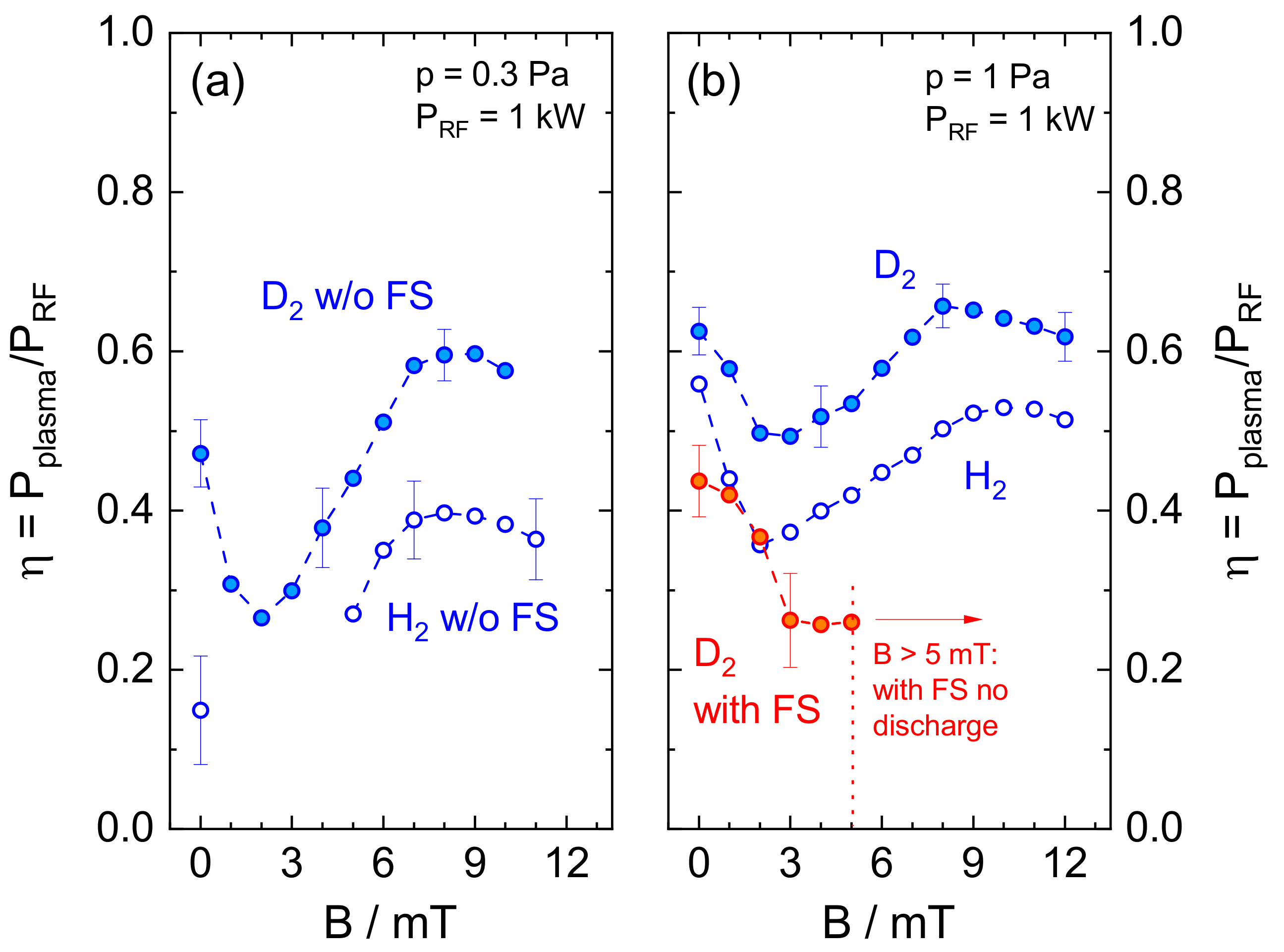
The measured RF power transfer efficiency with the Nagoya antenna in hydrogen (without FS) and in deuterium (with and without FS) at a varying axial magnetic field between 0 and 12 mT are shown in Figure 6, exemplary for 0.3 Pa in (a) and for 1 Pa in (b). At both pressures, displays a similar behavior in both hydrogen and deuterium if no Faraday shield is applied. For example in deuterium at 0.3 Pa, increasing the magnetic field leads to a significant decrease of from at until a minimum at 2 mT is reached. At higher field, a steep increase to a local maximum efficiency of more than at 9 mT is displayed. The same trend at overall slightly higher efficiency and less relative variation with B is evident at 1 Pa and in hydrogen. With H, is systematically lower compared to deuterium. This implies that at 0.3 Pa and between 1 mT and 4 mT, no stable discharge operation is possible with H at .
Due to the Faraday shield, the RF power transfer efficiency is significantly reduced in analogy to the ICP results. At 0.3 Pa (and in hydrogen in general), this fully suppresses discharge ignition and operation. In deuterium at 1 Pa and 0 mT, stable plasma operation is possible with FS, but drops to . With increasing magnetic field, the efficiency decreases similar to the trend without Faraday shield until at 3 mT a minimum is reached. With FS however, the RF power transfer efficiency does not increase again. Above 5 mT, neither discharge ignition nor operation is possible, not even with the maximum available RF power of up to 2 kW.
3.2.2. Discussion
The occurrence of local, B-dependent enhancements of the RF power coupling (resulting, e.g., in a maximum of the electron density) is a typical feature of low-field helicons conventionally referred to as low-field peak(s) [24,38]. It originates in the reflection and interference of excited wave modes and is a typical indication that the discharge is operated in a wave-heated or wave-assisted regime [24,39]. Comparable observations have been reported for hydrogen/deuterium discharges operated at different operating conditions several times before, either also in view of an enhanced RF power transfer [20] or reflected within other parameters such as the atomic or electron density [20,40].
The results presented in Figure 6 thus indicate that the internal Faraday shield suppresses the transition of the discharge from an inductive mode at to a wave heated regime with increasing magnetic field. In fact, the behavior of the discharge with FS strongly resembles the performance of an (increasingly) magnetized ICP, where B gradually reduces the RF coupling efficiency as the electron mobility is limited due to gyration [40].
The reason for the inability to reach the wave-heated regime with Faraday shield can be associated with the RF power absorption mechanism, and thus related with the conditions defining the excitation and damping of relevant wave modes: unlike high power/high field helicon discharges that provide conditions where RF power deposition solely via the damping of the helicon waves themselves can be sufficient (e.g., via electron-ion collisions [1,41]), in low-field helicons the electron density is typically not high enough (in the present case of the order of ). Here, the power deposition occurs via the strongly damped Trivelpiece–Gould (TG) modes, which are coupled to the excited helicon waves under certain boundary conditions once the finite electron mass is considered, as comprehensively reviewed, e.g., by Chen [24].
Against this background, the observed behavior is interpreted as follows: apart from the primary effect of localizing the electrostatic field component outside of the plasma volume, the internal Faraday shield also changes the boundary conditions for wave propagation, as it introduces a conducting lateral wall. As described in-depth for example by Shamrai and Taranov [42], the coupling of TG and helicon wave modes is fundamentally altered in this case: a non-conducting boundary leads to a strong coupling between TG and helicon waves, associated with an enhancement of the TG field amplitudes and thus, the potential of damping (i.e., power absorption) also at lower densities. A conductive wall, however, results in a separation of TG and helicon eigenmodes. Thus, only helicons are excited, which are insufficiently damped to provide plasma heating. This leads to the changed power absorption observed in the experiment. However, a deeper assessment would require the dedicated (theoretical and experimental) assessment of the wave modes in the present experimental geometry, which is well beyond the scope of this work. Nevertheless, this entails fundamental consequence for low-field helicons in view of their suggested application at high RF power, e.g., at ion sources for fusion. If (due to the high heat load) a metallic Faraday shield indeed remains to be a prerequisite, any plasma generation mechanism relying on RF power deposition via damping of TG waves is apparently not a viable option.
4. Conclusions
Applying internal Faraday shields considerably impacts different aspects of RF driven low pressure hydrogen (and deuterium) discharges. In case of a cylindrical ICP operated well within the H-mode, two prominent effects stand out. First, the internal Faraday shield reduces the RF power transfer efficiency—in analogy to externally applied Faraday shields. This effect is mainly due to increased power losses originating in eddy currents within the electrostatic shield. Further aspects like a larger coil-plasma distance or a changed composition of neutral particles within the bulk plasma contribute only to a small extent to the power coupling. Hence, if maximizing the RF coupling with such a Faraday shield is desired, a dedicated redesign of its geometry aiming for minimum losses is considered to be a promising option.
The second main effect of the Faraday shield is a significant decrease of atomic density of about one order of magnitude in the bulk plasma. It is caused by the elevated recombination probability of hydrogen atoms on the metallic (Cu) surface of the FS in comparison to the dielectric (quartz) walls. Vice versa, changing the material (or plating/covering the plasma-exposed surfaces) of the FS could be the tool of choice to control the atomic to molecular density ratio in a desirable fashion.
By applying an internal Faraday shield with a Nagoya-type III helicon antenna, a transition of the discharge to a wave heated regime is fully suppressed at the present experimental conditions and at low magnetic fields. This is attributed to fact that the plasma is in direct contact with a conducting lateral vessel wall due to the Faraday shield. This changes the boundary conditions for wave propagation, effectively decoupling helicon and TG wave modes and rendering efficient power deposition at these conditions impossible. This questions the viability of low-field helicons that rely on RF power absorption via damping of TG waves as an alternative for plasma generation at high power RF sources where internal Faraday shields are a necessity.
Author Contributions
Conceptualization: D.R., D.Z., S.B., U.F.; Methodology, investigation, formal analysis and validation: D.R., D.Z.; writing—original draft preparation, visualization: D.R.; writing—review and editing: all; supervision, project administration: S.B., U.F.; funding acquisition, U.F. All authors have read and agreed to the published version of the manuscript.
Funding
This work has been carried out within the framework of the EUROfusion Consortium and has received funding from the Euratom research and training programme 2014–2018 and 2019–2020 under grant agreement No 633053. The views and opinions expressed herein do not necessarily reflect those of the European Commission. This work has been carried out within the framework of the EUROfusion Consortium, funded by the European Union via the Euratom Research and Training Programme (Grant Agreement No 101052200—EUROfusion). Views and opinions expressed are however those of the author(s) only and do not necessarily reflect those of the European Union or the European Commission. Neither the European Union nor the European Commission can be held responsible for them.
Data Availability Statement
The data presented in this study are available upon reasonable request from the corresponding author.
Conflicts of Interest
The authors declare no conflict of interest.
Abbreviations
The following abbreviations are used in this manuscript:
| RF | Radio frequency |
| ICP | Inductively coupled plasma |
| FS | Faraday shield |
| TG | Trivelpiece-Gould |
References
- Chabert, P.; Braithwaite, N. Physics of Radio-Frequency Plasmas; Cambridge University Press: Cambridge, UK, 2011. [Google Scholar]
- Lieberman, M.A.; Lichtenberg, A.J. Principles of Plasma Discharges and Materials Processing, 2nd ed.; John Wiley & Sons: Hoboken, NJ, USA, 2005. [Google Scholar]
- Godyak, V.A.; Piejak, R.B.; Alexandrovich, B.M. Experimental setup and electrical characteristics of an inductively coupled plasma. J. Appl. Phys. 1999, 85, 703–712. [Google Scholar] [CrossRef]
- Hopwood, J. Planar RF induction plasma coupling efficiency. Plasma Sources Sci. Technol. 1994, 3, 460–464. [Google Scholar] [CrossRef]
- Suzuki, K.; Nakamura, K.; Ohkubo, H.; Sugai, H. Power transfer efficiency and mode jump in an inductive RF discharge. Plasma Sources Sci. Technol. 1998, 7, 13. [Google Scholar] [CrossRef]
- Sugai, H.; Nakamura, K.; Suzuki, K. Electrostatic coupling of antenna and the shielding effect in inductive RF plasmas. Jpn. J. Appl. Phys. 1994, 33, 2189–2193. [Google Scholar] [CrossRef] [Green Version]
- Khater, M.H.; Overzet, L.J. Stabilizing inductively coupled plasma source impedance and plasma uniformity using a Faraday shield. J. Vac. Sci. Technol. A 2001, 19, 785–792. [Google Scholar] [CrossRef]
- Hikosaka, Y.; Nakamura, M.; Sugai, H. Free Radicals in an Inductively Coupled Etching Plasma. Jpn. J. Appl. Phys. 1994, 33, 2157–2163. [Google Scholar] [CrossRef]
- Edamura, M.; Yoshioka, K.; Nishio, R.; Kanai, S.; Kanekiyo, T.; Kanno, S.; Mise, N.; Doi, A.; Kazumi, H. A Novel Plasma Etching Tool with RF-Biased Faraday-Shield Technology: Chamber Surface Reaction Control in the Etching of Nonvolatile Materials. Jpn. J. Appl. Phys. 2003, 42, 7547–7551. [Google Scholar] [CrossRef]
- Speth, E.; Ciric, M.; Feist, J.; Frank, P.; Heinemann, B.; Kraus, W.; Probst, F.; Riedl, R.; Trainham, R.; Vollmer, O.; et al. RF ion sources for fusion applications: Design, development and performance. Fusion Eng. Des. 1999, 46, 383–388. [Google Scholar] [CrossRef]
- Fantz, U.; Hopf, C.; Wünderlich, D.; Friedl, R.; Fröschle, M.; Heinemann, B.; Kraus, W.; Kurutz, U.; Riedl, R.; Nocentini, R.; et al. Towards powerful negative ion beams at the test facility ELISE for the ITER and DEMO NBI systems. Nucl. Fusion 2017, 57, 116007. [Google Scholar] [CrossRef] [Green Version]
- Marcuzzi, D.; Agostinetti, P.; Palma, M.D.; Falter, H.D.; Heinemann, B.; Riedl, R. Design of the RF ion source for the ITER NBI. Fusion Eng. Des. 2007, 82, 798–805. [Google Scholar] [CrossRef] [Green Version]
- Chen, P.; Li, D.; Chen, D.; Song, F.; Zuo, C.; Zhao, P.; Lei, G. Electromagnetic and thermal analyses of Faraday shield of various materials and structures for an ICP source. AIP Conf. Proc. 2018, 2052, 040018. [Google Scholar] [CrossRef]
- Christmann, K. Interaction of hydrogen with solid surfaces. Surf. Sci. Rep. 1988, 9, 1–163. [Google Scholar] [CrossRef]
- Rauner, D.; Briefi, S.; Fantz, U. RF power transfer efficiency of inductively coupled low pressure H2 and D2 discharges. Plasma Sources Sci. Technol. 2017, 26, 095004. [Google Scholar] [CrossRef] [Green Version]
- Rauner, D.; Briefi, S.; Fantz, U. Influence of the excitation frequency on the RF power transfer efficiency of low pressure hydrogen ICPs. Plasma Sources Sci. Technol. 2019, 28, 095011. [Google Scholar] [CrossRef]
- Zielke, D.; Rauner, D.; Briefi, S.; Lishev, S.; Fantz, U. Self-consistent fluid model for simulating power coupling in hydrogen ICPs at 1 MHz including the nonlinear RF Lorentz force. Plasma Sources Sci. Technol. 2021, 30, 065011. [Google Scholar] [CrossRef]
- Franzen, P.; Fantz, U. On the NBI system for substantial current drive in a fusion power plant: Status and R&D needs for ion source and laser neutralizer. Fusion Eng. Des. 2014, 89, 2594–2605. [Google Scholar] [CrossRef]
- Ahmed, K.M.; Agnello, R.; Béchu, S.; Cartry, G.; de Esch, H.P.L.; Furno, I.; Guittienne, P.; Howling, A.; Jacquier, R.; Morgal, I.; et al. Magnetic field configurational study on a helicon-based plasma source for future neutral beam systems. Plasma Sources Sci. Technol. 2019, 28, 095005. [Google Scholar] [CrossRef] [Green Version]
- Santoso, J.; Manoharan, R.; O’Byrne, S.; Corr, C.S. Negative hydrogen ion production in a helicon plasma source. Phys. Plasmas 2015, 22, 093513. [Google Scholar] [CrossRef] [Green Version]
- Blackwell, D.D.; Chen, F.F. Two-dimensional imaging of a helicon discharge. Plasma Sources Sci. Technol. 1997, 6, 569. [Google Scholar] [CrossRef]
- Shinohara, S.; Takechi, S.; Kawai, Y. Effects of Axial Magnetic Field and Faraday Shield on Characteristics of RF Produced Plasma Using Spiral Antenna. Jpn. J. Appl. Phys. 1996, 35, 4503–4508. [Google Scholar] [CrossRef]
- Watari, T.; Hatori, T.; Kumazawa, R.; Hidekuma, S.; Aoki, T.; Kawamoto, T.; Inutake, M.; Hiroe, S.; Nishizawa, A.; Adati, K.; et al. Radio-frequency plugging of a high density plasma. Phys. Fluids 1978, 21, 2076–2081. [Google Scholar] [CrossRef]
- Chen, F.F. Helicon discharges and sources: A review. Plasma Sources Sci. Technol. 2015, 24, 014001. [Google Scholar] [CrossRef] [Green Version]
- Briefi, S.; Rauner, D.; Fantz, U. Determination of the rotational population of H2 and D2 including high-N states in low temperature plasmas via the Fulcher α transition. J. Quant. Spectrosc. Radiat. Transfer. 2017, 187, 135–144. [Google Scholar] [CrossRef] [Green Version]
- Briefi, S.; Fantz, U. A revised comprehensive approach for determining the H2 and D2 rovibrational population from the Fulcher-α emission in low temperature plasmas. Plasma Sources Sci. Technol. 2020, 29, 125019. [Google Scholar] [CrossRef]
- Wünderlich, D.; Fantz, U. Evaluation of State-Resolved Reaction Probabilities and Their Application in Population Models for He, H, and H2. Atoms 2016, 4, 26. [Google Scholar] [CrossRef] [Green Version]
- Wünderlich, D.; Scarlett, L.H.; Briefi, S.; Fantz, U.; Zammit, M.C.; Fursa, D.V.; Bray, I. Application of molecular convergent close-coupling cross sections in a collisional radiative model for the triplet system of molecular hydrogen. J. Phys. Appl. Phys. 2021, 54, 115201. [Google Scholar] [CrossRef]
- Janev, R.K.; Langer, W.D.; Douglass, J.E. Elementary Processes in Hydrogen-Helium Plasmas: Cross Sections and Reaction Rate Coefficients; Springer: Berlin/Heidelberg, Germany, 1987; Volume 4. [Google Scholar]
- Chantry, P.J. A simple formula for diffusion calculations involving wall reflection and low density. J. Appl. Phys. 1987, 62, 1141–1148. [Google Scholar] [CrossRef]
- Green, M.; Jennings, K.R.; Linnett, J.W.; Schofield, D. Recombination of atoms at surfaces. Part 7.-Hydrogen atoms at silica and other similar surfaces. Trans. Faraday Soc. 1959, 55, 2152–2161. [Google Scholar] [CrossRef]
- Wood, B.J.; Wise, H. The kinetics of hydrogen atom recombination on pyrex glass and fused quartz. J. Phys. Chem. 1962, 66, 1049–1053. [Google Scholar] [CrossRef]
- Melin, G.A.; Madix, R.J. Energy accommodation during hydrogen atom recombination on metal surfaces. Trans. Faraday Soc. 1971, 67, 2711–2719. [Google Scholar] [CrossRef]
- Kim, Y.C.; Boudart, M. Recombination of oxygen, nitrogen, and hydrogen atoms on silica: Kinetics and mechanism. Langmuir 1991, 7, 2999–3005. [Google Scholar] [CrossRef]
- Mozetič, M.; Drobnič, M.; Zalar, A. Recombination of neutral hydrogen atoms on AISI 304 stainless steel surface. Appl. Surf. Sci. 1999, 144–145, 399–403. [Google Scholar] [CrossRef]
- Hansen, B.F.; Billing, G.D. Hydrogen and deuterium recombination rates on a copper surface. Surf. Sci. 1997, 373, L333–L338. [Google Scholar] [CrossRef]
- Sode, M.; Schwarz-Selinger, T.; Jacob, W.; Kersten, H. Surface loss probability of atomic hydrogen for different electrode cover materials investigated in H2-Ar low-pressure plasmas. J. Appl. Phys. 2014, 116, 013302. [Google Scholar] [CrossRef] [Green Version]
- Chen, F.F. Experiments on helicon plasma sources. J. Vac. Sci. Technol. A Vac. Surfaces Film. 1992, 10, 1389–1401. [Google Scholar] [CrossRef]
- Shinohara, S. Helicon high-density plasma sources: Physics and applications. Adv. Phys. X 2018, 3, 1420424. [Google Scholar] [CrossRef] [Green Version]
- Briefi, S.; Gutmann, P.; Rauner, D.; Fantz, U. Comparison of the B field dependency of plasma parameters of a weakly magnetized inductive and Helicon hydrogen discharge. Plasma Sources Sci. Technol. 2016, 25, 035015. [Google Scholar] [CrossRef]
- Chen, F.F. Plasma ionization by helicon waves. Plasma Phys. Control. Fusion 1991, 33, 339. [Google Scholar] [CrossRef] [Green Version]
- Shamrai, K.P.; Taranov, V.B. Volume and surface rf power absorption in a helicon plasma source. Plasma Sources Sci. Technol. 1996, 5, 474. [Google Scholar] [CrossRef]
Figure 1.
(a) Experimental setup and applied diagnostics. In (b), the RF coil and the internal Faraday shield utilized in the ICP configuration are shown, in (c) the Nagoya type-III antenna with the corresponding Faraday shield for the helicon setup is shown.
Figure 1.
(a) Experimental setup and applied diagnostics. In (b), the RF coil and the internal Faraday shield utilized in the ICP configuration are shown, in (c) the Nagoya type-III antenna with the corresponding Faraday shield for the helicon setup is shown.

Figure 2.
(a) RF power transfer efficiency of ICPs with and without Faraday shield and (b) corresponding plasma equivalent and loss resistances at varying pressure.
Figure 2.
(a) RF power transfer efficiency of ICPs with and without Faraday shield and (b) corresponding plasma equivalent and loss resistances at varying pressure.

Figure 3.
(a) Electron density, (b) electron temperature and (c) density ratio of atomic to molecular hydrogen of ICPs with and without Faraday shield. All parameters are plotted against the pressure.
Figure 3.
(a) Electron density, (b) electron temperature and (c) density ratio of atomic to molecular hydrogen of ICPs with and without Faraday shield. All parameters are plotted against the pressure.

Figure 4.
(a) Estimation of the dissociation rate according to Equation (3) with and without Faraday shield and at varying pressure. (b) Wall recombination probability required to balance the dissociation rate depicted in part (a).
Figure 4.
(a) Estimation of the dissociation rate according to Equation (3) with and without Faraday shield and at varying pressure. (b) Wall recombination probability required to balance the dissociation rate depicted in part (a).

Figure 5.
(a) Comparison of the experimentally measured RF power transfer efficiency with and without Faraday shield at varying pressure with the associated results obtained by the self consistent fluid simulation. (b) Contribution of different effects caused by the Faraday shield to the total reduction of the RF power transfer efficiency, as obtained from the simulation at a pressure of 3 Pa.

Figure 6.
RF power transfer efficiency of the helicon discharge utilizing a Nagoya type III antenna in H and D for a varying magnetic field at 0.3 Pa (a) and at 1 Pa (b).
Figure 6.
RF power transfer efficiency of the helicon discharge utilizing a Nagoya type III antenna in H and D for a varying magnetic field at 0.3 Pa (a) and at 1 Pa (b).


Table 1.
Typical range of experimentally measured and theoretically determined values of the surface recombination coefficient (at ) of hydrogen atoms on different materials as reported in literature.
Table 1.
Typical range of experimentally measured and theoretically determined values of the surface recombination coefficient (at ) of hydrogen atoms on different materials as reported in literature.
| Material | Surface Recombination Coefficient |
|---|---|
| quartz/silica [31,32,33,34] | – |
| stainless steel [33,35] | ≈0.1 |
| copper [32,33,36] | 0.05–0.15 |
| other metals [32,33] | 0.05–0.5 |
Publisher’s Note: MDPI stays neutral with regard to jurisdictional claims in published maps and institutional affiliations. |
© 2022 by the authors. Licensee MDPI, Basel, Switzerland. This article is an open access article distributed under the terms and conditions of the Creative Commons Attribution (CC BY) license (https://creativecommons.org/licenses/by/4.0/).
Share and Cite
MDPI and ACS Style
Rauner, D.; Zielke, D.; Briefi, S.; Fantz, U. Impact of Internal Faraday Shields on RF Driven Hydrogen Discharges. Plasma 2022, 5, 280-294. https://doi.org/10.3390/plasma5030022
AMA Style
Rauner D, Zielke D, Briefi S, Fantz U. Impact of Internal Faraday Shields on RF Driven Hydrogen Discharges. Plasma. 2022; 5(3):280-294. https://doi.org/10.3390/plasma5030022
Chicago/Turabian StyleRauner, David, Dominikus Zielke, Stefan Briefi, and Ursel Fantz. 2022. "Impact of Internal Faraday Shields on RF Driven Hydrogen Discharges" Plasma 5, no. 3: 280-294. https://doi.org/10.3390/plasma5030022