1. Introduction
The global economic, social and environmental development face some problems and limitations due the necessity to improve information and communication technologies [
1]. Efforts are currently being made to increase the capacity of fast and long-range telecommunications, added to the support of global information networks and the survey of natural resources and meteorological. It could be solved by space systems, such as the small constellations of nanosatellites in low orbits, close to Earth [
2]. The interest in creating new space systems has grown in recent decades and the two of the biggest companies in the space industry, SpaceX and One Web, have announced their intentions to launch thousands of satellites in the next 5 years [
2].
Satellites requires frequent correction and maintenance of the orbit. It implies an increase in propellant consumption and, consequently, the need for a small propulsion system with a high specific impulse [
3]. One solution to this demand is electrical propulsion (EP) systems that accelerate ions to exhaust velocities one or two orders of magnitude greater than classical chemical motors, leading to improved specific impulse [
4]. This feature dramatically reduces the amount of propellant needed, allowing for longer mission times and heavier payloads [
4]. The downside is the low ion mass production rate, which is limited by the reduced electrical energy that can be made available on board, further limiting the thrust levels that can be achieved. EP systems are characterized by low thrusts and high specific impulses. These features are essential for orbital maneuvers, station maintenance, flight formation, and end-of-life disposal of small constellation satellites intended for global internet coverage [
4].
EP systems are classified according to the ion acceleration method, thus dividing it into three categories: electrothermal, electromagnetic, and electrostatic [
5]. Each category has several different types of thrusters, with strengths and weaknesses, always requiring an assessment of which factors will be most important for the satellite or space probe mission. Among these categories, electrostatic thrusters are the ones that present several studies regarding the thruster and/or propellant [
5,
6,
7,
8,
9,
10,
11].
In the gridded ion thruster (GIT), a type of electrostatic thruster, ions are accelerated by a stationary electric field. Ions are produced in a plasma (propellant) and extracted from it through electrically polarized grids with high velocities producing the thrust [
5]. The plasma is usually generated in radio frequency inductively coupled plasma (RF-ICP) system [
7]. Xenon gas is the most used propellant in the GIT due to its high molar mass and for being a noble gas with 131 atomic mass unit (amu) [
8]. However, xenon is expensive and has an ionization threshold energy of 12.1 eV [
12]. Another propellant that has been used in thrusters is argon gas [
13,
14,
15,
16]. It has low weight, 40 amu, and, consequently, highest exhaust velocities. However, it has a higher ionization threshold energy than xenon, i.e., 15.76 eV, which increases the energy consumption for ion production. However, the advantage of using argon is that it is cheaper than xenon.
In order to improve the efficiency of GIT and find the best propellant alternatives it is necessary to study gas ionization process. Computational modeling can efficiently contribute to such goals, saving time and resources. Plasma modeling allows the study of plasma chemistry and complements experimental diagnostics under test conditions that are experimentally inaccessible [
17]. In plasma modeling, the global model stands out for allowing the studying of complex plasma chemistries with a low computational cost [
18].
The global model is a zero-dimensional model originating from fluid theory [
18]. It comprises a set of differential equations of species density and energy that are temporally solved. Some global models have been developed to study ion thruster systems. In 2012, Chabert et al. developed a global model for ICP-type ion thruster with grids to estimate the efficiency of the xenon propellant [
19]. Chabert included the energy balance of the neutral species in global model and analyzed the effect of gas temperature in plasma chemistry. In 2016, Grondein et al. applied this model to iodine, thus taking a first comparison between the respective efficiencies of both propellants [
12]. These models did not consider the external neutralizer, which was eventually included by Dietz et al. in 2020 [
20]. To date, there is no global model in the literature for GIT using argon as propellant.
Argon plasma is composed of grounded state argon, Ar; argon ion, Ar
+; electrons, e
−; and several excited species. The excited species can be ionized and contribute to propulsion efficiency. For modeling argon plasma, some models consider only one excited specie, the metastable, Ar
m, and others also include the resonant, Ar
r, and 4p states, Ar
p. The metastable corresponds to states
3P
0 and
3P
2 and have a long lifetime compared to other excited species [
21]. The states
1P
1 and
3P
1 compose the resonance level. The Ar
p is composed of the next ten energy levels in the range of 12.9–13.5 eV.
In this study, a global model for GIT was developed to analyze the argon plasma chemistry and investigate the gas ionization process. This work investigated the role of excited species in plasma chemistry, especially in ion production and its implications for propulsion parameters, such as thrust. Thus, this study was carried out in two different scenarios: (1) one taking into account the three excited species Ar
m, Ar
r, and Ar
p and the ionization of theme (multi-step ionization) and (2) the other without Ar
r and Ar
p species and considering only ionization from fundamental state (single-step ionization). The global model was developed taking as reference the models proposed by Chabert et al. [
19] and Grondein et al. [
12]. In the energy balance for neutral species, new terms were introduced to the equation to study the dependence of the gas temperature on collisional processes.
2. Global Model
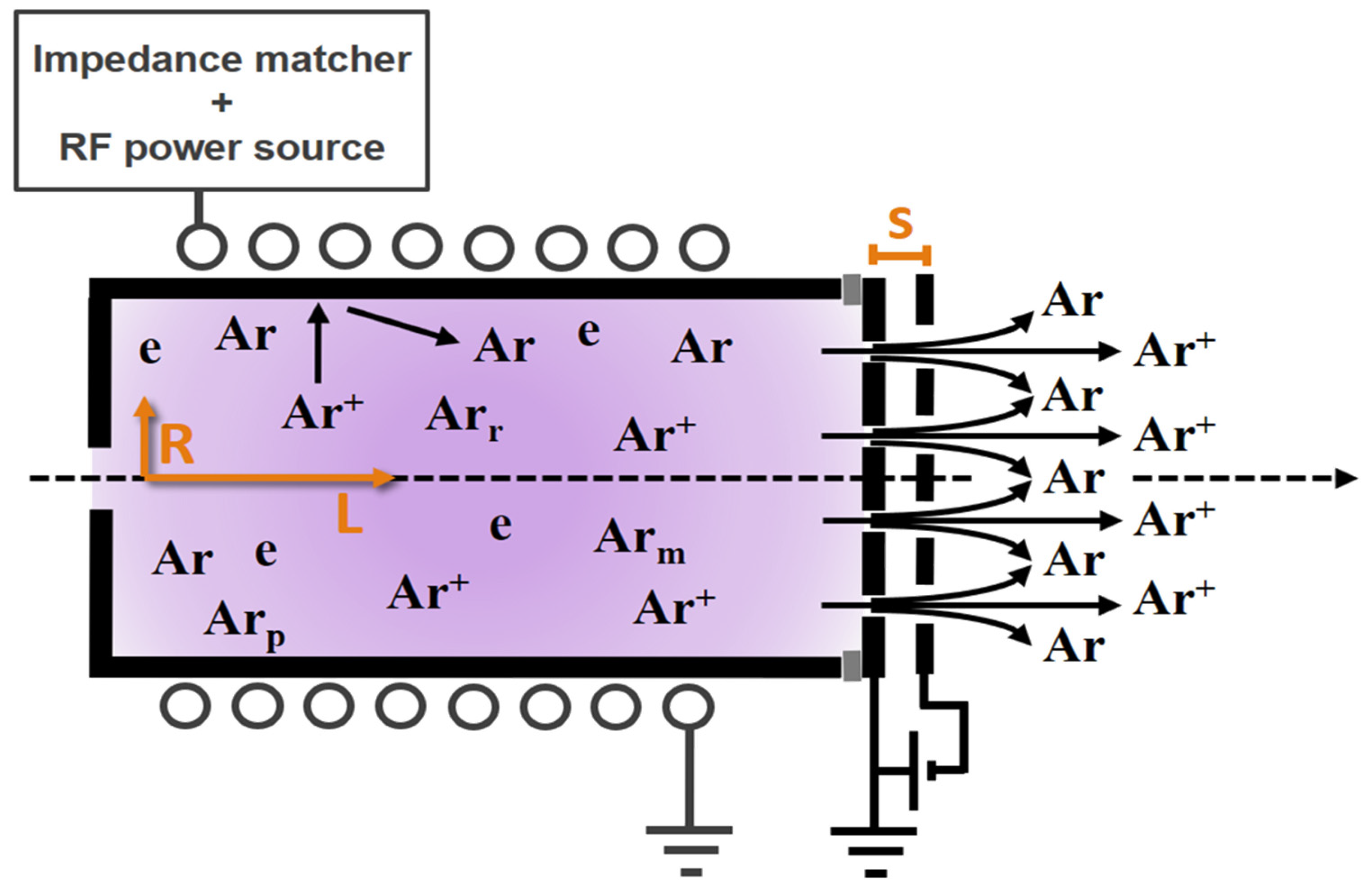
In this global model, the thruster geometry consists of a cylindrical chamber of radius
and length
, so that the total internal area is
and the volume is
. At the propellant inlet, neutral gas is introduced at a fixed flow rate
, while the opposite end features a pair of screen grid and accelerator grid, separated by a gap
, as shown in the scheme of
Figure 1.
Neutral gas flux is defined as , where is the neutral gas density and is the average velocity of atoms as a function of gas temperature; is expressed in Kelvin and is the mass of the argon. The neutral gas flow out of the thruster through the area is given by , where is the transparency coefficient for neutral atoms. This can vary between , and for there is no neutral gas escape from the thruster. Analogously, the area through which the ions escape is , denoting as the grid transparency for ions, assuming that the ion transparency is independent of the ion mass.
Neutral flow out of the thruster depends on the gas density and gas temperature, when the thruster is turned on. Therefore, before the plasma is turned on, when it is in steady state, it is possible to determine the neutral gas flow rate as
, where
and
are the neutral gas density and the mean velocity without plasma, respectively [
22]. From the equation of state
, by substituting the neutral gas density, we obtain:
The flow of ions leaving the impeller is composed of single ionized species, since the argon is at low pressure and its escape velocity is a function of the acceleration caused by the voltage difference between the two grids,
, and elemental charge,
:
Finally, by means of the volume averaging technique for a global model, a set of linear differential equations, which are composed of particle balance equations for each argon gas/plasma species and two equations for the energy balance, is solved [
23,
24]. Details concerning these equations are presented in the next topics.
2.1. Particle Balance
In this model, a plasma was considered to be composed of three mutual particle interactions: between neutral atoms, positive ions with a single charge, and electrons. These interactions are listed in
Table 1, which considers production and loss through many processes, including reactions between electrons and gas species, reactions between two gas species, the recombination of neutral species on the chamber walls, the neutralization of positive ions on the walls of the chamber, the quenching of the metastable states in the chamber walls, and the insertion of gas species into the chamber and pumping out of these species. For each species, there is a particle equilibrium equation given by [
25]:
where
represents the sum of all reaction rates that contribute to the production of species
, and
represents the sum of all reaction rates that contribute to the loss of species
. There is a reaction rate for each reaction considered in the model. Reaction rates are calculated as the product of the densities of the species participating in the reaction and the rate coefficient of this reaction. The electron density is obtained through charge neutrality [
26]:
where
is the electron density and
is the ion density.
2.1.1. Neutralization of Positive Ions on Chamber Walls
Ions can diffuse to chamber walls and are neutralized when they collide with the wall surface. Their reaction constant is a loss term in the balance equation, which is given by [
27,
28]:
where
is the area for effective loss, and
and
are termed the axial and radial coefficients for the positive ion density ratio in the sheath edge with respect to the plasma center, respectively. A simplified form of previously used proportions for low and intermediate densities follow Godyak’s formulation [
29]:
The ion-neutral cross section
needed to calculate the mean free path of the ion
was assumed to be
= 5 × 10
−18 m
2 [
30].
2.1.2. Neutral Recombination and Metastable Extinction on the Chamber Walls
The surface interactions of the neutral particles considered in the model are summarized in
Table 1. The coefficient rate for the effective losses of the neutral particles in the wall is given by [
31]:
where
is the diffusion coefficient of neutral particles [
31],
is the recombination/extinction coefficient of neutral particles in the wall, and
is the effective length of neutral diffusion [
31]:
2.2. Neutral Gas Power Balance
Collisions between charged and neutral particles lead to significant gas heating. We use the following neutral energy balance equation to calculate the gas temperature (
) [
32]:
where
is the neutral energy density (in J/m
3),
is the gas heating due to electron-neutral elastic collisions,
is the ion-neutral collision heating,
is the heat flux to the walls. Heat is conducted to the chamber walls by thermal diffusion; the walls are at a fixed temperature
. Furthermore, we consider that
is the heat loss due to ionization collisions, and
is the heat loss due to ion-neutral collisions [
32,
33].
For the expression of
,
with
is the electron neutral momentum transfer rate; for
,
with
is the neutral ion transfer rate (we use
); and for
,
is the thermal conductivity of argon gas and
is the heat diffusion length [
32].
2.3. Electron Power Balance
The global power balance completes the set of differential equations. It can be written as follows [
34]:
where
is the energy density of the electron (in J/m
3);
is the power absorbed by the plasma;
is the lost power; and
is the volume of the discharge chamber. The power loss equation in its most general form is given by [
35,
36]:
where
is the power lost by positive ions to the walls,
is the ion density in the plasma sheath region,
is the Bohm average velocity, and
is the average kinetic energy lost by the ions in the walls; here
is the energy gained by the ion entering the plasma sheath and
is the potential drop in the sheath formed in the reactor walls [
37];
is the power lost by electrons to the chamber walls, where
is the internal area of the chamber,
is the average kinetic energy per electron lost and
is the electron density at the sheath edge; and
is the power lost due to electron–particle reactions.
In the mathematical expression for
, the sum is taken over all neutral species
x with positive ion counterparts (Ar) with a density
n(X), an ionization rate coefficient
, and collisional energy loss per electron–ion pair created,
, where the last is [
30]:
where
is the ionization energy of argon;
and
are the excitation energy and the coefficient rate for the
excitation process of species
, respectively;
is the coefficient of the elastic scattering rate of neutral argon; and
is the electron mass.
The power absorbed by the plasma,
, is given by a direct dependence on the inductive coupling used to excite the plasma. Thus,
is the difference between the power delivered by the RF generator by the generator’s impedance matcher,
, and the power dissipated by the coil (due to ohmic heating),
[
38]. In this formulation, anomalous field penetration and collision-free heating are not included, so the power delivered to the
RF is:
with
and
defined as
where
and
are the effective resistance of the equivalent circuit of the system composed by the plasma and the coil, respectively [
12].
In the electrical model, the plasma is generated by means of an electromagnetic field induced by an
RF current that surrounds the cylindrical chamber of the thruster with a coil of
turns of total length
. Since the respective inductance to this coil is given by
the coil radius,
, is greater than the chamber radius [
12,
19]. The total impedance of the system is
, where
and
are given by
So, the respective Bessel functions for zero order and for first order are
and
. Since
, with
and
is the speed of light,
is the electrical permittivity in vacuum and the plasma complex permittivity is given by [
19]:
2.4. Ar Plasma Chemistry
The chemistry of Ar plasma that was used in this study includes six species: ground state argon (Ar), positive argon ion (Ar+), metastable argon (Arm), resonant argon (Arr), atoms in the 4p state (Arp), and electrons (). Arm includes the two metastable states 3P0 and 3P2 and Arr includes two resonant states 1P1 and 3P1.
The 4p excited state has 10 energy levels in the range of 12.9–13.5 eV. The two metastable levels are combined in the calculations: the radiative and 4p levels.
Table 1 lists the reaction set for argon plasma. Collisions between electron and Ar atoms in the excited state (i.e., the R12–R17 reactions in
Table 1) were considered as they are believed to play an important role in the particle transfer processes in the argon plasma. The electron impact reaction rate coefficients were calculated by integrating the cross-sections over the assumed Maxwellian distribution.
Table 1.
Reactions and their corresponding reaction rates for argon used in the calculations. The subscripts
and
denote the resonance and metastable levels of the excited state
and the subscript
denotes the excited state
[
21].
Table 1.
Reactions and their corresponding reaction rates for argon used in the calculations. The subscripts
and
denote the resonance and metastable levels of the excited state
and the subscript
denotes the excited state
[
21].
| Nº | Reaction | Eth(eV) | Reaction Constant, k (m3 s−1) | Ref. |
|---|
| Elastic |
| 1 | Ar + e → Ar + e | - | | [37] |
| Direct ionization |
| 2 | Ar + e → Ar+ + 2e | 15.76 | | [39] |
| Multistep ionization |
| 3 | Arm + e → Ar+ + 2e | 4.43 | | [40] |
| 4 | Arr + e → Ar+ + 2e | 3.96 | | [40] |
| 5 | Arp + e → Ar+ + 2e | 2.26 | | [31] |
| Excitation |
| 6 | Ar + e → Arm + e | 11.50 | | [41] |
| 7 | Ar + e → Arr + e | 11.60 | | [42] |
| 8 | Ar + e → Arp + e | 12.90 | | [42] |
| De-excitation |
| 9 | Arm + e → Ar + e | −11.50 | | [41] |
| 10 | Arr + e → Ar + e | −11.60 | | [43] |
| 11 | Arp + e → Ar + e | −12.90 | | [43] |
| Collision between electrons and excited-state Ar atoms |
| 12 | Arm + e → Arr + e | 1.60 | | [44] |
| 13 | Arm + e → Arp + e | 1.20 | | [41] |
| 14 | Arr + e → Arp + e | 1.10 | | [41] |
| 15 | Arr + e → Arm + e | −1.60 | | [45] |
| 16 | Arp + e → Arm + e | −1.20 | | [46] |
| 17 | Arp + e → Arr + e | −1.10 | | [46] |
| Radiation trapping |
| 18 | Arr → Ar + hv | - | (s−1) | [47] |
| 19 | Arp → Arm + hv | - | (s−1) | [48] |
| 20 | Arp → Arr + hv | - | (s−1) | [48] |
2.5. Numerical Solution
The global model was solved using the COMSOL Multiphysics 5.4 software. Through the COMSOL differential equation solver, seven of the main variables of the model were calculated, these are the ground state gas density, ; the ionic density, ; the metastable density, ; the resonant argon density, ; the density of the atoms in the 4p state, ; the electron temperature, ; and the neutral gas temperature, . The calculation is performed by numerically integrating the differential equations of the mass balance and power balance, until the steady-state is reached. The steady-state values of these variables were then used to calculate the quantities of interest for electrical propulsion as detailed in the next topic.
3. Equations and Basic Concepts of Electrical Propulsion
The thrust is the result of the ejection of the propellant in the space and is given by the rate of change of the propellant’s momentum over time:
where
is the propellant mass and
is the propellant exhaust velocity that does not vary with time. Electric thrusters use sources of electrical energy to create and accelerate charged particles and thus eject them with higher exhaust velocities [
8].
The thrust produced by the ion beam through the opening of the transparent grating for the escape of ions is:
where
is the exhaust velocity of the ions. The power of the ion beam is given by:
The thrust of any non-ionized propellant can be estimated from the “random” flow through the grid opening to the neutral atoms, where
is the exhaust velocity of the neutrals, so [
8,
19]:
The power of the neutral flux to the outside of the thruster is given by [
12,
19]:
is expressed in units of seconds and can be seen as the ratio between the total thrust, the sum of the neutral thrust and the ion beam thrust, and the propellant consumption rate, which can be expressed as the exhaust velocity divided by gravitational acceleration.
The high exhaust velocities or high
allow the maximization of the mission’s payload mass making electric propulsion attractive. Another advantage of electric propulsion is the ability to vary the
throughout a mission, for example by reducing the amount of propellant not converted into charged particles [
8].
To study the efficiency from the parameters extracted from the global model, it was decided to analyze the following four efficiencies: (i) the mass utilization efficiency,
; (ii) the electrical efficiency,
; (iii) the ICP power efficiency,
; and (iv) the total efficiency,
, in order to calculate the thrust-to-power ratio,
, given in
, which is used to compare various types of EP as a function of
. Starting with the definition of
given by the mass flow rate of ions ejected by the mass flow rate of total input in the EP [
12,
19]:
Another way of evaluating the propeller efficiency is from the point of view of
, and this is carried out by measuring the power of the jet by the total input power:
The
, unlike the efficiencies
and
, takes into account the resistive factors:
The
is the kinetic power produced by the thruster, also known as the jet power, divided by the total power input to the thruster,
, and is given by:
A complementary approach to ion optics can be made by analyzing what happens when particles approach the gratings, resulting in the variation of potential and density in the plasma, in order to meet the equilibrium of the particles or the electrical conditions imposed by the inner walls of the discharge chamber. This region with a very large potential drop compared to the electron temperature is the Child–Langmuir sheath [
7,
8]. The Child–Langmuir sheath limits extraction to a certain current density. This relationship is expressed by Equation (31) of the Child–Langmuir limit, where
is the limit current density,
is the permittivity in space, and
is the distance between the grids [
5].
From Equation (31), the relationship of
can be observed, which is directly proportional to the voltage between the grids,
, and inversely proportional to the distance between the grids,
s. Based on the theory of electrical discharges, Paschen’s law describes the behavior of the breakdown voltage (
) for the product of the pressure by the distance between the electrodes, according to the
values found by Magaldi et al. [
49] is possible affirm that for the values of
and
s multiplied by the pressure inside the thruster, there is no possibility of a dielectric breakdown between the grids in the configuration used in this study.
To form a plasma sheath to accelerate the high-energy ions and reflect the electrons, the limiting distance of the plasma must be around the Child–Langmuir length. Therefore, the ideal distance,
s, between the grids for a better extraction, the Child–Langmuir length, is proportional to the mass of the ions [
25].
4. Results and Discussion
As previously highlighted, this global model study was carried out in two different scenarios: (1) one considering the metastable species Arr and Arp and (2) the other without considering these species. Thus, the comparison of the results with the complete set and another reduced set of reactions allowed for a better understanding of the real influence of metastable species in the proposed global model and how this accounting affected the GIT efficiencies.
Figure 2 presents the current density through the grids for the two reaction set configurations as a function of RF power. In this figure, it is evidenced how the ion current density without the two excited species is higher than with the metastables, this can be explained by the fact that the absence of the complete set is compensated for in the densities of the other species as shown in
Figure 3.
From Equation (32), the Child–Langmuir limit is plotted for both cases, and the two dashed lines are at 121.48 A/m
2 and 273.33 A/m
2. Two dashed vertical lines represent the corresponding power of 427.5 W for the complete set (case 1) and 848.2 W for the incomplete set (case 2).
Figure 3 shows the densities of each species (Ar, Ar
+, Ar
m, Ar
r, Ar
p, and
) calculated by the global model based on the parameters of
Table 2, based on the settings used in the references [
12,
19]. The RF power range chosen between 178 W and 1600 W corresponds to a current of 2 A to 10 A in the ICP coil, as a thruster of similar in size to the one modeled in this study is normally greater than 200 W [
12].
Still in
Figure 3, it is possible to observe a subtle drop in the neutral argon density, which may be associated with a gradual drop in neutral atoms as a consequence of excitations to metastable states and ionization. A second reason that explains this fact is the increase in the temperature of the gas,
, with the increase of the RF power, as shown in
Figure 4. There is an increase in the thermal velocity of the atoms leaving the propellant, reducing the density of neutral atoms. In the ionized argon curve, the degree of ionization shows a small, almost constant and proportional increase over the entire power range. With the percentages close to 3.5% and 4.2% when entering the Child–Langmuir limit range.
Argon plasma has a higher density of excited species than other more commonly used propellants, such as xenon and reference iodine [
12,
19]. These energy levels require less energy for ionization, favoring the replacement of argon ions over the plasma volume. In addition to presenting a higher density of neutral and ionized species compared to the aforementioned xenon and iodine, as a result of their smaller size. This higher ion density added to the almost immediate replacement of ions through the excited species allows for a possible compensation with respect to their lower atomic mass and higher ionization energy.
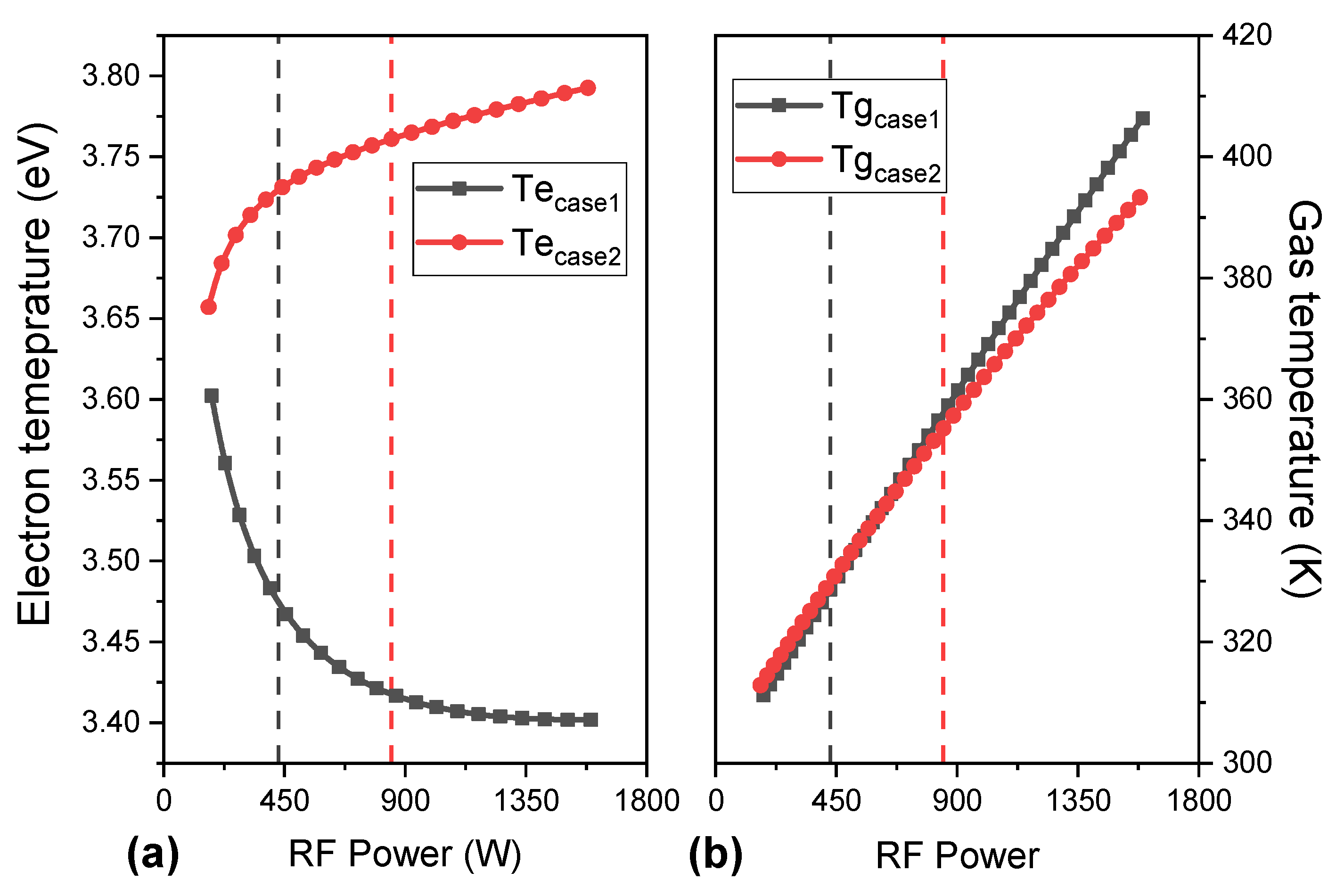
It is interesting to note in
Figure 4 that the
for the complete set decreases as the power is increased, which shows that this growth rate of the ionization curve is caused by the interactions of electrons with metastable species, which have a lower energy potential to ionize and thus the ionization equilibrium is maintained quickly without requiring a higher
, as in the beginning of plasma generation with energetically charged species. On the other hand, the
with the incomplete set does not have this energy compensation provided by the metastables, causing the need for a higher
so that the electrons can ionize the neutral argon atoms. The
drop of the complete set is significant, of almost 0.2 eV, with the subsequent increase in power reaching 3.4 eV at the Child–Langmuir limit. This favors the hypothesis that after ionic equilibrium is established, the energy exchange from collisions with electrons occurs with a lower
. This small temperature difference of
with the complete set and without the complete set is due to the account of the greater number of interactions between the neutral species in the multistep process of argon ionization.
For a better understanding of which gain and loss terms in Equation (10) contribute more to the heating of the gas as the power is increased, these were evaluated separately as a function of the RF power and are shown in
Figure 5. The Equation (10) is based on the study developed by Chabert et al. and Grondein et al. [
12,
19]. Only gas-heating gains due to electron-neutral elastic collisions,
, and from ion-neutral collision heating,
, were accounted for, while the only losses are accounted for by heat flow to the walls,
. Other collisional losses were accounted for but do not enter the overall neutral gas energy balance. These collisional losses added to the equilibrium equation were called the heat loss due to ionization collisions,
, and the heat loss due to ion-neutral collisions,
. It is undeniable that the high energy loss of
ended up being counted as an energy gain species in this case, but it was preferred to keep it as a loss term, as defined by Golant et al. in [
33] and highlighted by Liard et al. in [
32]. This thermal gain caused by not accounting for
is reflected in an increase in
. In terms of
, it is not a value that can interfere in the calculation of species densities nor in their values along the RF power.
It is understandable to raise the question regarding the ability of these ion-neutral collisions plus the metastable species from the complete set to result in an increase in the temperature . In the global model, it is not common to delve deeper into the study of possible inaccuracies that the adopted assumptions may cause, but in general evaluations, the energy balances are associated within the system of differential equations and in this way this energy from does not go to the and goes somewhere else, which could be the electrons. However, the conjecture presented—that the electrons, when receiving this energy, would raise the —was not proven when studying the contribution of this energy loss, since the and the density of the species did not show variation. The maintenance of densities brings the information that this energy was not enough to form new ionized species and that because the plasma is semi-neutral, it would justify an increase in the density of electrons in an amount similar to that of positive charges, which in turn could alter until. As a result of the subsequent results, the unaccounted energy may be linked to the kinetic energy of the species, which would result in an increase in .
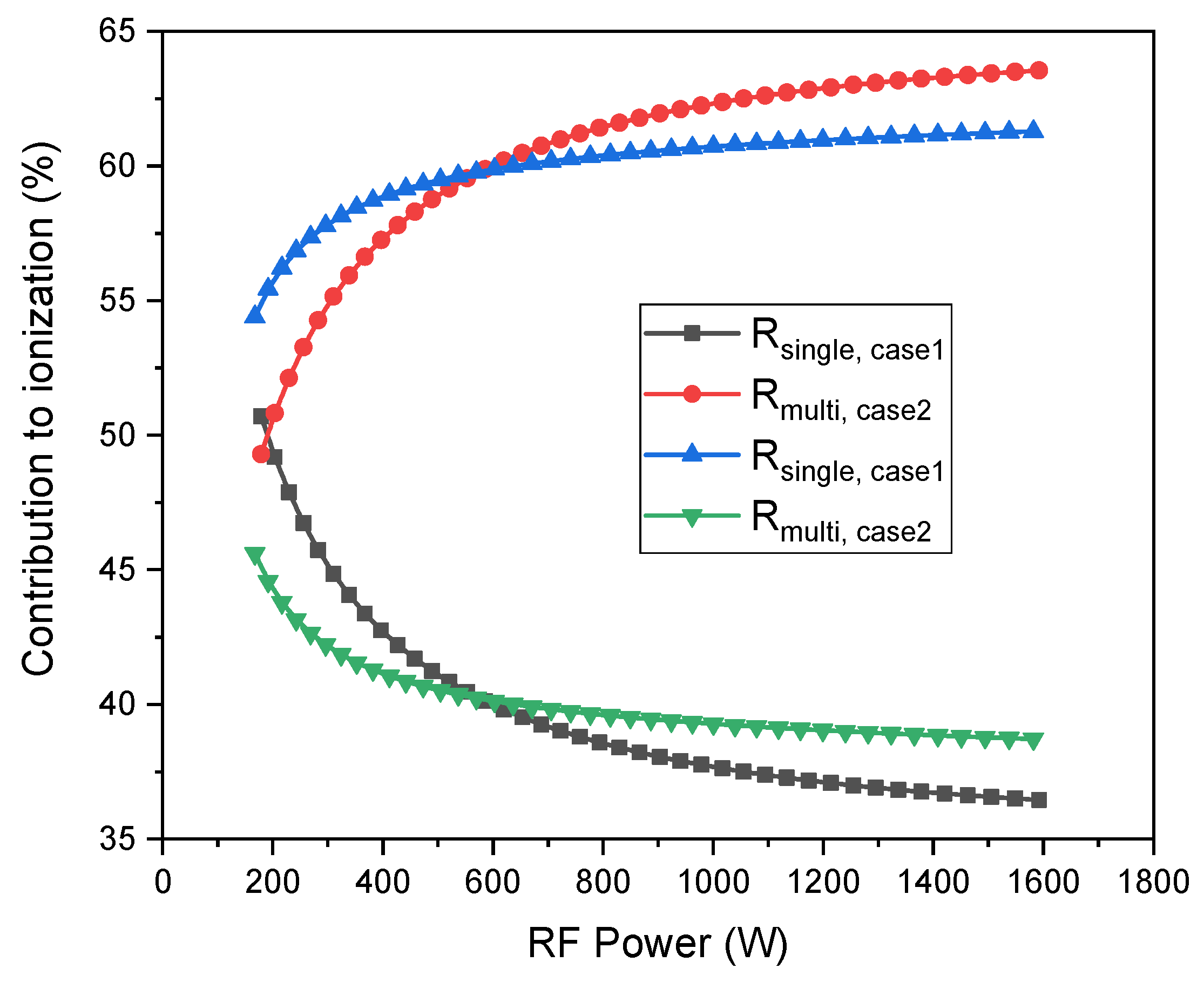
Figure 6 shows the contribution to ionization as the RF power is increased. It is important to remember that when talking about the incomplete set, it still presents the Ar
m species and that is why the multistep is discussed in this case. In
Figure 6 it is evident with increasing RF power that the Ar
r and Ar
p species greatly increase the contribution to ionization, this fact being confirmed by all the other analyzes presented so far. The energy that the electron spends on average to perform an ionization is provided by collision energy. The collisional energy is a function of the reaction constants; therefore, even if the excited species were disregarded in the calculation and considering the balance of particles in addition to ionizations and elastic collisions, the electron would have spent energy in the production of metastables [
17]. In case the excited species were not accounted for, a smaller number of excitations were performed, which resulted in a reduction of the energy spent for the generation of an electron–ion pair. The increase in
shown in
Figure 5, means that the probability of ionization tends to increase as the power increases, and this may be motivated by a smaller number of reactions of other types. The reactions, similar to those of the excited species, are a direct consequence of the ionization constants rising in front of the other distributions. Therefore, the population of high-energy electrons produces ionizing reactions, thus decreasing
, as shown in
Figure 4.
Figure 7 shows a comparison between the inductively coupled plasma (ICP) power transfer efficiency,
; the mass transfer efficiency,
; the electrical transfer efficiency,
; and the total efficiency,
, for both models with and without the complete set. In terms of the comparison between with and without the complete set, it is evident that the
does not change; the
and
for the complete set tend to be smaller, but with a small increase for
and a constant increase that is slightly smaller than that without
when it is raised to RF power; and finally, the
which presents a reasonable drop. These drops present a characteristic that is much closer to real efficiency, and although they are a reduction in efficiency, they do not represent a negative point, since they are very positive results.
The electrical efficiency remained close to 80% (a very good value for argon, which has a high ionization potential), which confirms that the energy transfer through the excited species is a great potential of the argon propellant. The low mass transfer efficiency was expected, due to the size of the argon atom and its molar mass. Total efficiency is a parameter that has appeared more frequently in the new literature and serves as a reference between the different types of thrusters and their different physical properties.
Now taking what has been shown in
Figure 6, where it is evident that step-wise ionization favors an increase in the global ionization as the contribution of the Ar
r and Ar
p species reduces the energy consumption in the formation of ions. However, the contribution in case 1 of low RF power is smaller than in case 2. This reflects a reduction in the aforementioned efficiencies but does not reflect a loss of efficiency, rather an efficiency closer to what was expected for reality. In this way, the comparison of the thrust produced with the accounting of energetic species, as well as some efficiencies, was lower, as shown in
Figure 8. For an RF power of 450 W, approximately 40 mN was delivered, which represents a remarkable thrust value for electric thrusters.
With the intention of obtaining a comparison, knowing that in the literature no results were found with the desired experimental parameters, an alternative was to compare the results of Chabert et al., where the thruster was calculated by the global model of xenon plasma [
19]. This comparison must be seen based on the Child–Langmuir limits, which physically delineate where the result found by the simulation is possible. The Child–Langmuir limits of
Figure 8 are: 428 W for argon (case 2), 848 W for argon (case 1), and 1160 W for xenon [
19], corresponding to approximately 45 mN, 80 mN, and 60 mN, respectively. Although in
Figure 8, for high power values, the thrust produced by argon exceeds that produced by xenon, the Child–Langmuir limit of argon was exceeded, therefore not corresponding to reality. Generally speaking, for RF power up to 430 W the thrusts for both plasmas are close.
5. Conclusions
In this work, a global model was developed to study electric propulsion with two extraction grids operating with argon gas at a pressure of 2 mTorr. The analysis of the generated plasma was divided into scenarios with (multi-step ionization or case 1) and without (single-step ionization or case 2) the complete reaction set, having explored a set of 20 reactions in the plasma volume. Additionally, the model includes the energy balance of the neutral species, thus allowing the determination of the neutral gas temperature and thus verifying the propellant heating level for the investigated operational parameters.
It was expected that the metastable state Arm would make a significant contribution to the mechanism of maintaining the ion density in the creation and extraction process of the thruster due to its long lifetime, in the order of a few seconds. The novelty was being able to make this comparison of the other resonant species, Arr, and the ten energy levels of argon corresponding to the 4p configuration, Arp, in a global model made in detail for a GIT.
There was also a strong dependence of the density of ions and excited species with the power, which increases by up to an order of magnitude for the investigated power range. On the other hand, the electron temperature was reduced with RF power, corroborating with the results observed in the literature.
In the propulsion aspects, a thrust of practically 40 mN at 450 W with the complete set was observed, the efficiencies found were used as a comparison with other types of electric propulsion, being able to satisfy a group of specific missions that require up to 3000 s of specific impulse and other parameters used.


