
The Development of a High-Static Low-Dynamic Cushion for a Seat Containing Large Amounts of Friction

School of Engineering, University of Guelph, Guelph, ON N1G 2W1, Canada
*
Author to whom correspondence should be addressed.
Vibration 2024, 7(2), 388-406; https://doi.org/10.3390/vibration7020020
Submission received: 7 January 2024
/
Revised: 1 April 2024
/
Accepted: 15 April 2024
/
Published: 25 April 2024
Abstract
:Exposure to whole-body vibration (WBV) has been shown to result in lower-back pain, sciatica, and other forms of discomfort for operators of heavy equipment. While WBV is defined to be between 0.5 and 80 Hz, humans are most sensitive to vertical vibrations between 5 and 10 Hz. To reduce WBV exposure, a novel seat cushion is proposed that optimally tunes a High-Static Low-Dynamic (HSLD) stiffness isolator. Experimental and numerical results indicate that the cushion can drastically increase the size of the attenuation region compared to a stock foam cushion. When placed on top of a universal tractor seat, the cushion is capable of mitigating vibrations at frequencies higher than 1.1 Hz. For comparison, the universal tractor seat with a stock foam cushion isolates vibrations between 3.4 and 4.1 Hz, as well as frequencies larger than 4.8 Hz. Friction within the universal seat is accurately modeled using the Force Balance Friction Model (FBFM), and an analysis is conducted to show why friction hinders overall seat performance. Finally, the cushion is shown to be robust against changes in mass, assuming accurate tuning of the preload is possible.
1. Introduction
Exposure to seated whole-body vibration (WBV) from heavy equipment may contribute to adverse effects on human health, including lower-back pain, sciatica, and other injuries [1,2,3]. WBV is typically defined as being between 0.5 Hz and 80 Hz [4], though the perception of these vibrations depends on the magnitude of acceleration as well as the axis it acts along [5]. Morioka et al. found that the maximum sensitivity to WBV in the vertical axis occurs between 5 and 10 Hz [5]. To this end, slow-moving vehicles are of concern as their motion generally results in lower-frequency excitation forces. Low-frequency vibrations are difficult to attenuate using traditional passive isolators due to the mechanical limitations of springs [6]. Below the cut-off frequency, traditional linear isolators amplify vibrations rather than attenuate them, potentially worsening the effects of WBV for the operator.
Several seat designs have been proposed within the literature to combat the limitations of passive linear isolators. Active and semi-active seats use a control scheme and electronic feedback to actively attenuate vibrations transmitted to the operator. Several studies have shown that such systems are capable of isolating low-frequency vibrations much better than traditional passive systems [7,8,9,10]. However, active and semi-active systems suffer from increased complexity and cost when compared to simpler passive systems. Commercial products using this technology such as the John Deere Active Seat [11] and Bose Ride System [12] are designed to replace the entire seat in modern heavy equipment. This adds additional cost and limits the ability of the seat to be universally mounted into any kind of equipment.
An alternative isolator technology shown to attenuate WBV makes use of the principle of quasi-zero stiffness (QZS). Le et al. [13] designed and validated a seat suspension that incorporates negative stiffness into the main seat suspension. Within this work, the entire seat is considered as a single-degree-of-freedom (SDOF) system, where the seat and cushion are simply considered to be rigid parts. Their research confirms that through careful tuning of the SDOF negative stiffness elements, the seat can have a more desirable dynamic response compared to without these elements in place. These results are derived through experimental investigations for various values of nonlinear stiffness.
Wang et al. [14] modeled an adaptive QZS system as a three-degree-of-freedom system where the seat, vehicle body, and vehicle wheel make up the three degrees. The paper focuses on the impulse response of the system rather than the entire frequency response. Through simulations, the results show that a passive QZS seat suspension can decrease peak acceleration, improve rider comfort, and decrease attenuation time when compared to a linear system. When active control is applied to the QZS system, the acceleration of the human body is decreased to zero, rider comfort is further improved, and the seat stroke remains within its allowed range when compared to the simpler passive case.
Guo et al. [15] performed an in-depth review of High-Static Low-Dynamic (HSLD) isolators and then used a double-diamond structure to develop a conceptual design of a seat cushion that incorporates QZS elements. The design consists of many small isolators placed in parallel within the cushion and is evaluated using analytical models and an Automated Dynamic Analysis of Mechanical Systems (ADAMS) software simulation. The results show that the cushion is expected to perform significantly better than a linear isolator, decreasing the natural frequency of the cushion from 13.78 Hz to 3.2 Hz.
Unlike most previous studies, the current paper proposes a low-profile isolator designed to replace an existing heavy-equipment seat cushion rather than the entire seat. Similar to the concept of Guo et al., the device uses the principle of HSLD stiffness, which can be tuned optimally to achieve the QZS condition. However, unlike the conceptual cushion by Guo et al. [15], the design presented here uses one large QZS element rather than many small elements in parallel. The present study will show that this poses several advantages, particularly in the tunability of the device to compensate for different operator masses. In addition, a prototype of the design is developed and tested. The novel cushion aims to leave the existing seat suspension untouched and simply replaces the existing seat cushion with a new one. This is particularly beneficial for maintaining a low device cost, while providing new vibration attenuation options for a wide range of industries. The low profile aims to maintain the form factor of existing seat cushions within many heavy-equipment vehicles. For applications such as underground mining, an isolating cushion is particularly useful, since vertical size limitations of the machines do not allow for large complex vehicles or seat suspensions. In these applications, replacement of the existing seat cushion is the only viable option for eliminating WBV.
The main focus of the proposed design is to isolate low-frequency vibrations that the existing seat suspensions are not able to attenuate. When used in conjunction with the existing suspension, the aim of the cushion is to increase the attenuation bandwidth. The design was evaluated as a standalone SDOF system, as well as a two-degree-of-freedom (2DOF) system when incorporated into a tractor seat. The tractor seat used as the frame of reference was the T300 Universal Tractor Seat developed by Darby Manufacturing. In each case, the dynamic performance was evaluated based on the ability of the device to (1) reduce the resonant frequency and increase the attenuation zone when compared to the linear system, (2) decrease the magnitude of the resonant peak, and (3) isolate high-frequency mechanical vibrations, evaluated using the rate of decay of the transmissibility plot. The American Society of Agricultural and Biological Engineers (ASABE) guideline for agricultural equipment operator seats was used as a frame of reference, which suggests that the lower limit for a typical passive seat suspension would have a natural frequency of around 1.2 Hz for steel or rubber springs, and 0.8 Hz for air springs [6]. Considering that the attenuation zone of a linear system begins at √2ωn, where ωn is the natural frequency of the system. This guideline would correlate to a cut-off frequency of 1.70 Hz for steel springs and 1.13 Hz for air springs.
QZS systems have been shown in the past to be sensitive to parameters such as spring stiffness, system geometry, and the mass placed on top of it [16,17,18]. For the application of a heavy-equipment seat cushion, this is of importance since the mass of an operator can vary substantially. For this reason, the ability of the device to accommodate a variety of masses is investigated.
2. Materials and Methods
2.1. System Modeling
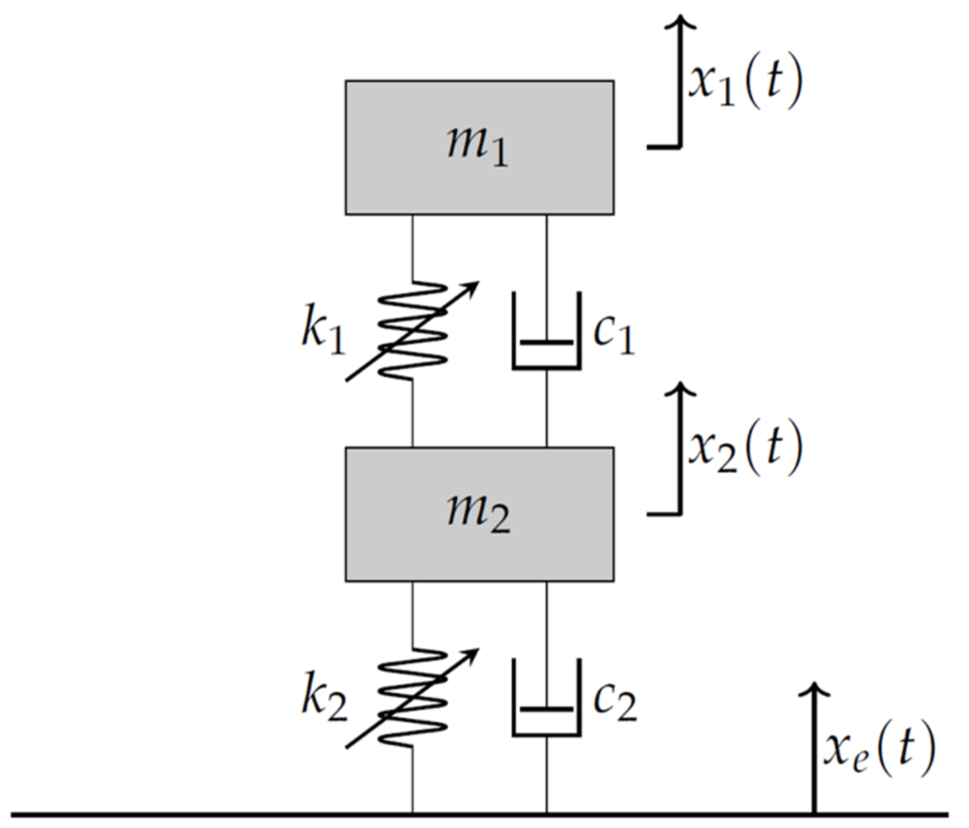
The seat was modeled mathematically as a two-degree-of-freedom system with a combination of linear and nonlinear elements. A model of the device can be seen in Figure 1, where mass 1 represents the mass of the operator and mass 2 represents the mass of the seat suspension.
The static and dynamic properties of HSLD systems are well understood within the literature [19,20,21,22,23]. In most cases, HSLD stiffness is achieved by combining positive and negative stiffness elements in parallel. As shown in Figure 2, when tuned properly, these elements can be combined to create a region of near-zero stiffness, known as the QZS condition.
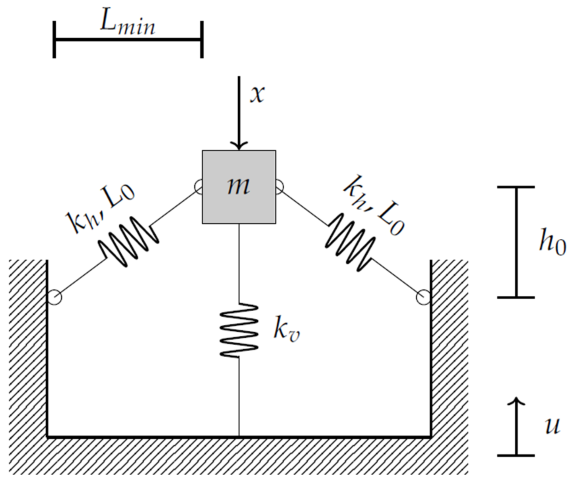
While positive stiffness elements are readily available in many forms, negative stiffness is usually achieved using oblique springs, magnetism, or cam mechanisms. The prototype cushion proposed within this paper makes use of oblique springs, so this is the focus of this study. A diagram of the oblique spring mechanism is shown in Figure 3. This spring mechanism is the nonlinear stiffness element which connects the masses of the nonlinear system shown in Figure 1.
The equations of motion for the nonlinear system in Figure 1 can be expressed as follows:
where and are the mass, damping, vertical stiffness, horizontal stiffness, oblique spring free length, and oblique spring minimum horizontal lengths of the nth layer, respectively. and are the relative displacements. This system is nonlinear and is difficult to solve analytically. Instead, the nonlinear portion is converted into an approximate polynomial equation using Taylor’s formula. This approximation is accurate while [24], that is, the following holds:
When considering a base excitation of , the equations of motion can be written as follows:
where . This approximate equation of motion is linear and can be utilized to develop analytical solutions for the displacement transmissibility of the system. The full process is shown in detail by Lu et al. [25], which considers all damping to be viscous. The transmissibility is defined as follows:
The majority of commercially available tractor seats contain other forms of friction and therefore cannot be accurately modeled using simple linear techniques [26,27]. With friction, the equation of motion for a 2DOF system undergoing base excitation becomes as follows:
where is the force of friction within the upper and lower parts of the system. The literature presents many potential mathematical models for friction. This study will mainly focus on the Force Balance Friction Model (FBFM) [28,29], which can efficiently represent the sticking and sliding conditions. While sticking, an SDOF system undergoing base excitation is not able to overcome the internal friction forces of the system, hence exhibiting a relative velocity of zero. The system enters the sliding state once the internal forces minus the external forces are greater than the static friction capacity.
While sliding, the force of friction can be evaluated as follows:
where μ is the static friction coefficient and is the normal force. The condition for sticking is satisfied when the magnitude of the relative velocity is smaller than a small limiting velocity () and the net tangential force is less than the friction capacity (). Hassan et al. [29] provided a comprehensive review of the available friction models and the challenges in terms of their applicability and accuracy. While their results showed agreement among the FBFM, the Spring Damper Friction Model (SDFM), and the experimental results, the SDFM requires the implementation of two additional parameters (frictional spring and damper). The choice of these two additional parameters is specific to individual applications and requires careful tuning. On the other hand, the FBFM does not require any additional tuning parameters and has excellent accuracy.
2.2. Simulations
For the application of the universal tractor seat in combination with the novel QZS cushion, the general mathematical model presented in System Modeling can be simplified to suit the specific application. The universal seat consists of a simple linear spring and damper, so the nonlinear stiffness is omitted for this portion of the model. Similarly, the internal damping within the QZS cushion is small and can be modeled satisfactorily using viscous damping rather than the FBFM. Simplifying these nonlinearities helps decrease the computational power required for the simulations while providing reasonable accuracy.
In this work, all of the systems where friction is not considered are solved analytically using the assumption shown in Equation (3). In the presence of friction, analytical solutions are difficult to attain and numerical solutions using a 4th order Runge-Kutta method are employed. The Runge-Kutta algorithm uses a variable time step to ensure high computational efficiency. Where applicable, models are verified using data from the literature. In particular, the SDOF QZS model is verified using the equations presented by Lu et al. [30] and Carrella et al. [21].
2.3. Experiments
The purpose of the experimental portion of this study was to investigate the ability of the novel QZS cushion to reduce the WBV experienced by an operator. To accomplish this, the dynamic response of the novel cushion was compared to alternatives using the three performance criteria outlined in the introduction. The cushion dynamics were investigated both as an individual SDOF system as well as a 2DOF system when it was placed on top of the universal tractor seat base with the original cushion removed. This response was compared with the response of the standalone universal seat, which can be considered a single-degree-of-freedom system without any cushions, and with the response of the 2DOF universal tractor seat with the regular foam cushion on top of it. The experimental results were also used to develop and verify mathematical models of the universal seat and QZS cushion. As seen in Figure 4, a six-degree-of-freedom Mikrolar R-3000 hexapod robot was used to provide 5 mm peak-to-peak vertical sinusoidal vibrations to the base of the seat and cushions. A frequency sweep was carried out from 0.5 Hz to 9 Hz, with 0.1 Hz increments in critical areas and 0.5 Hz increments elsewhere. Prior to data collection, a pilot data collection step was performed to identify critical areas. Critical areas were defined as regions on the transmissibility curve with large changes in the transmission ratio between frequency steps. In these areas, the frequency step size was reduced from 0.5 Hz to 0.1 Hz. The transmission ratio is defined as x/, where x is the displacement of the mass in question and is the excitation displacement.
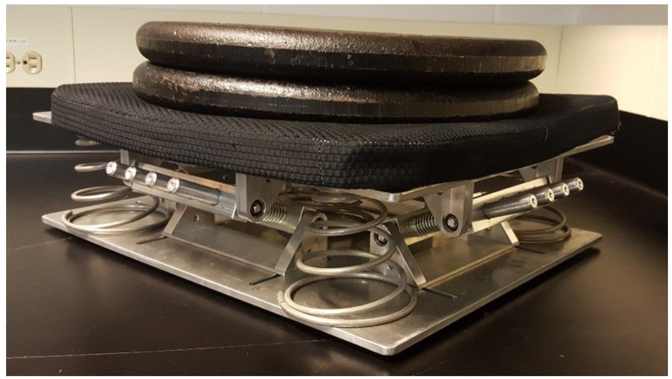
The motion of the base and mass 2 were measured using two triaxial accelerometers (model 356A17, PCB Piezotronics, Depew, NY, USA) whereas the motion of mass 1 was measured using a uniaxial accelerometer (model 333B40, PCB Piezotronics, Depew, NY, USA). Since the motion of the vibration simulator was purely in the vertical direction, only the motion in the Z axes of all accelerometers was considered. Lateral motion was not analyzed. In cases where acceleration was measured on top of a foam cushion, a rubber seat pad as described in ISO 10326-1 [31] was used to house the accelerometer. The mechanism of the novel QZS cushion is shown in Figure 5 with a one-inch polyurethane foam pad placed on top for rider comfort. It included five vertical conical springs in parallel, as well as sixteen oblique springs placed along the outside of the cushion. The oblique springs were arranged such that four springs counteract one another along the long and short sides of the cushion, thereby allowing the mechanism to only move in the vertical direction.
Stiffness Verification
Previous studies have shown that HSLD systems, particularly those tuned to be near the QZS region, are very sensitive to changes in the vertical stiffness [16,17,18]. Considering this, to accurately model the system, it is insufficient to rely on the specification of the springs, which can vary as much as ±3% of the actual spring stiffness [32]. Instead, a tensile testing machine (Instron Model 5969) was used to obtain an accurate force–displacement plot, thereby allowing the stiffness to be derived. The SDOF universal seat along with the horizontal and vertical stiffness components of the QZS system were all tested using this method. The force–displacement plot for the universal seat is shown in Figure 6, tested near the front of the seat as well as near the back of the seat. In both cases, all cushions were removed from the device, ensuring the seat suspension was the only source of seat dynamics. Figure 6a shows the force–displacement plot when the Instron applied a force near the front of the seat. During this test, there was an increased possibility of cantilever deflection in the seat, as shown in Figure 7. For comparison, Figure 6b is obtained by compressing the seat near the backrest. The tests revealed that the average stiffness varied from 2250 N/m at the front of the seat to 3240 N/m near the back.
In general, only the linear (vertical) degree of freedom is considered. The rotating motion due to the cantilever effect is assumed to be much stiffer than the seat’s suspension. Regardless of the test method, the seat displayed nonlinear characteristics throughout its stroke. While the average stiffness of the seat appeared to be linear, localized sections of the motion range in stiffness from very stiff to negative stiffness. For example, between 8 mm and 18 mm, the slope of Figure 6a is slightly negative. Between 19 mm and 22 mm, the slope is very large. While these localized differences in stiffness can partially be attributed to friction or damping forces within the system, the results are repeatable across multiple tests. Considering that the dynamic tests within this paper use a base excitation of 5 mm peak-to-peak amplitude, this is of concern because the stiffness experienced throughout the motion has some uncertainty. The overall bilinear nature of the plots in Figure 6 is due to a large preload on the universal seat. The seat contains about 600 N of preload, though the preload stroke portion is not experienced while the mass is in motion in the experiments. The 5 mm peak-to-peak motion is entirely within the ”Seat Stroke” region, as shown in Figure 6.
Using similar techniques, the stiffness of the vertical and oblique springs within the QZS cushion was verified. As shown in Figure 5, the QZS cushion contains five vertical conical springs in parallel and sixteen oblique springs. To obtain the most accurate insights into the overall vertical stiffness, the five springs were tested in the Instron simultaneously while within the QZS system, rather than on an individual basis. This accounts for any internal stiffness properties that the machine may have. During this test, the oblique springs were removed from the device, and the data were collected at a loading rate of 10 cm/min. Figure 8a shows that the conical springs are linear in nature, with a slight stiffening effect near the end of the plot. Figure 8b indicates that the oblique coil springs are even more linear in nature. Ten oblique springs were tested simultaneously to account for random variations within the parts’ properties. Based on the slope of the stiffness plots within the regions where the dynamics take place during the vibration tests, the overall vertical stiffness is 22,840 N/m and a single oblique spring has a stiffness of 1519 N/m.
2.4. SDOF Nonlinear Model Verification
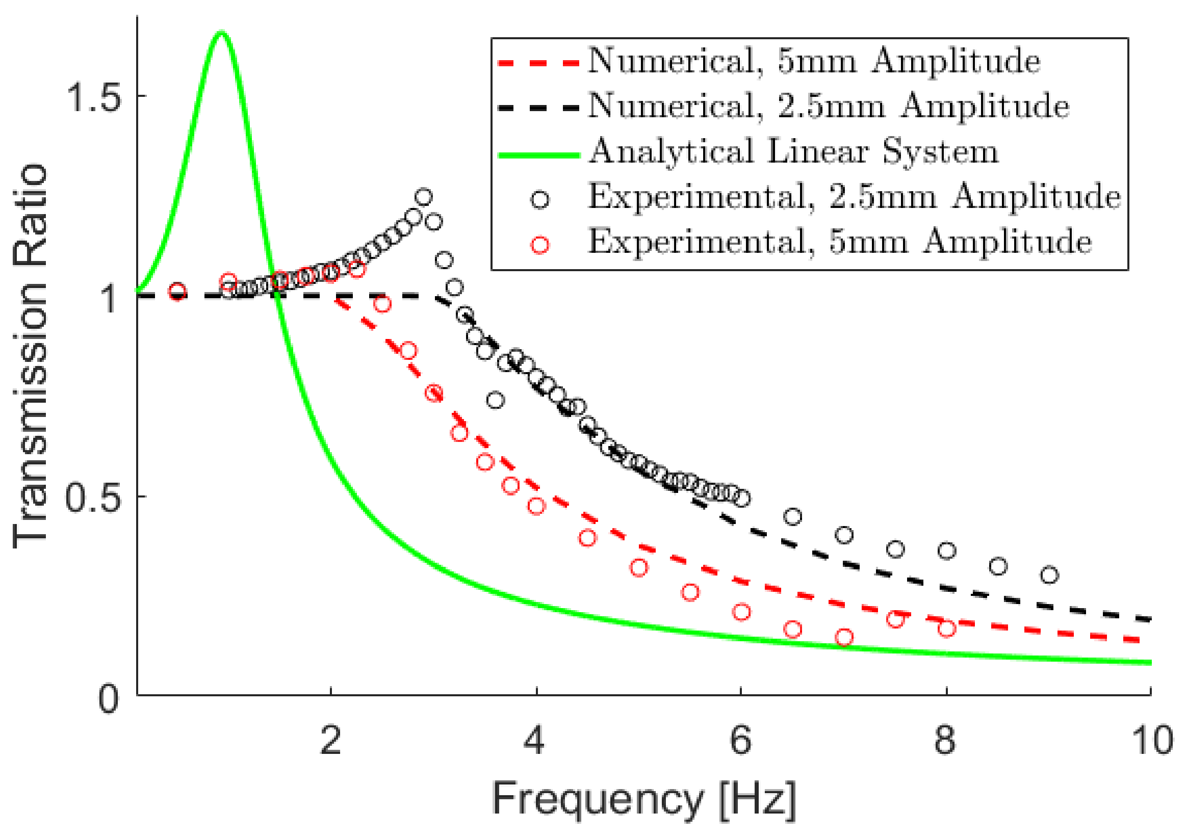
An SDOF mathematical model of the QZS cushion and the universal seat was created using the model described in System Modeling. In the case of the universal seat, all cushions were removed, leaving the suspension of the seat as the only dynamic component. For the QZS cushion, the device was placed directly onto the base of the vibration simulator, and all foam cushions were removed from the top surface of the device. Figure 9 shows the experimental frequency response of the universal seat for 2.5 mm amplitude (5 mm peak to peak) and 5 mm amplitude (10 mm peak to peak) base excitation. Vibration frequency, amplitude (mm), and RMS acceleration (mm/s2) for each vibration profile are shown in Table A1. Given the measured mass and stiffness properties of the system, the expected linear dynamic response is shown in green.
From Figure 9, it is apparent that the seat cannot reasonably be modeled as a linear system. The experimental response exhibits a resonant frequency that is far larger than expected, and the attenuation zone begins much sooner than at √2ωn. Furthermore, the response is dependent on the amplitude of the base excitation, which would not be the case for a linear system. Although the numerical simulations underestimate the transmission ratio at the resonant frequency, the numerical simulations provide a much better approximation of the transmission ratio compared to the linear system. These nonlinearities are attributed to the significant friction present within the system. While testing the seat, care was taken to clamp any loose components, eliminating this as a source of misleading dynamics. For example, the fore-aft adjustment in the seat was clamped to remove the vibrations within the seat related to the sliding mechanism’s forgiving tolerances. These clamps can be seen in Figure 10.
Using the friction model described in System Modeling, it is necessary to estimate the magnitude of the friction force present within the seat. This is found through direct experimentation. While at rest, there is a 39 mm range where the seat ”sticks” when supporting an 81.9 kg mass. By balancing the forces, the magnitude of the static friction is approximated using the following equation:
where , ∆x is the maximum sticking range, k is the stiffness of the system, μs is the static friction coefficient, and Fn is the normal force. In this experiment, the normal force is assumed to be constant throughout the motion.
The physical properties of the QZS system used within the simulations are summarized in Table 1. Properties of the stiffness elements are obtained using the tensile testing method described above. The mass is obtained by summing the mass of the weight, the top platform of the QZS cushion, and half of the mass of the dynamic components within the cushion. The mass of 81.9 kg is selected because it is approximately the mass of an operator supported by a cushion. An operator’s total mass may be in the order of 80–100 kg, but about 15–30% of this mass may be supported by other components of the cab (i.e., the floor, steering wheel, etc.) [6,33]. Finally, the damping ratio is obtained by curve fitting the experimental and mathematical solutions.
3. Results
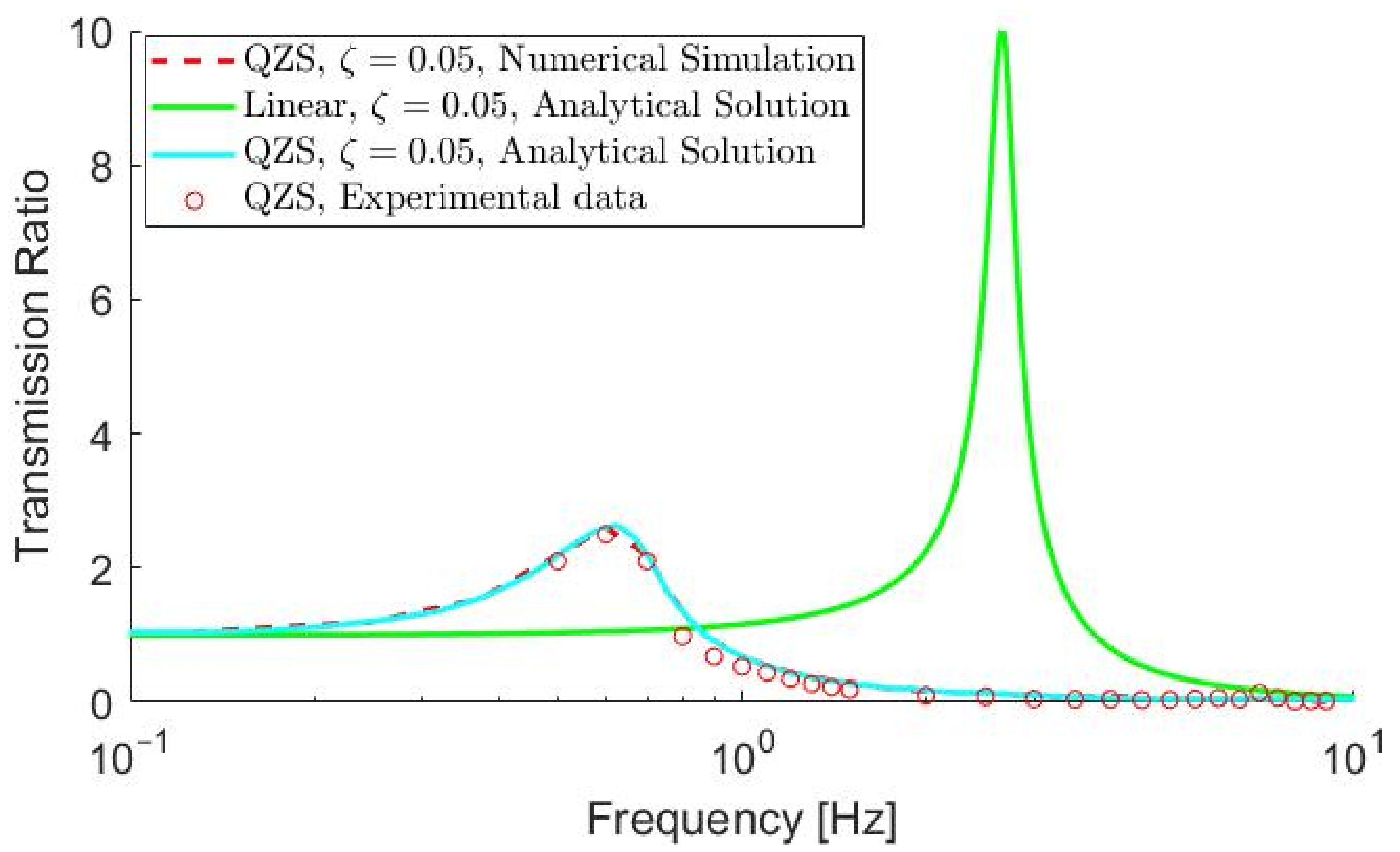
The results of the nonlinear model utilizing the FBFM are shown in Figure 9. The model accurately predicts the shift in the attenuation zone compared to the linear system and is robust against changing magnitudes of base excitation. However, it underestimates the amplification seen experimentally at low frequencies below the cut-off frequency. Within the bandwidth, the FBFM assumes the “sticking” state, hence exhibiting a transmission ratio of 1. The FBFM is more accurate when the seat experiences large excitation amplitudes, such as 10 mm peak to peak, since the mass can overcome friction forces at lower frequencies. Figure 11 compares the SDOF response of the QZS cushion to the approximate analytical and exact numerical simulations for the system. As can be seen, the two mathematical models fit the experimental data very well. This is especially true considering the sensitivity of the system to mass, stiffness, and geometrical tolerances [16,17,18]. For reference, Figure 11 includes the plot of a linear system with identical mass, vertical stiffness, and damping properties to that of the QZS system. The addition of the oblique springs in the QZS system drastically reduces the resonant frequency and the magnitude of the amplification when compared to the linear system.
The 2DOF Universal Seat with Cushions
The transmissibility curve for the overall seat can be seen in Figure 12. The figure compares the experimental responses of the 2DOF universal seat in combination with the stock foam cushion, the QZS system by itself, and the QZS system with the one-inch polyurethane foam pad on top. The figure also displays the expected response for the universal seat with the QZS cushion based on the numerical simulations. It is apparent that the QZS cushion drastically improves the dynamic response of the seat experienced by the operator. The addition of the one-inch polyurethane foam pad on top of the QZS system adds rider comfort while having a minimal effect on the overall seat dynamics—leading to a small shift in resonant frequency, from 0.8 to 0.9 Hz, and a slight increase in the transmissibility ratio, from 2.97 to 3.2 (Figure 12).
Many studies consider foam cushions to be very stiff, damped devices that therefore do little to change the dynamics of a system [13,14]. Within these studies, the cushions are not modeled separately, and their dynamics are simply lumped with the seat suspension itself. In the application considered in this paper, this assumption is accurate for the thin, polyurethane foam pad used on top of the QZS system but does not hold true for the thicker polyurethane cushion that is part of the universal seat. Figure 12 shows that the addition of the thicker stock cushion adds another resonant peak to the transmissibility curve around 4.5 Hz. While this cushion adds rider comfort, it comes at the cost of increasing the WBV experienced by the operator.
On the contrary, the one-inch polyurethane foam pad on top of the QZS mechanism does little to change the dynamics. This is shown in two ways. First, Figure 13 shows that the dynamic response of the cushion by itself results in a transmissibility of nearly 1 for the entire bandwidth between 0.5 and 9 Hz, with a small resonance peak appearing near the end of the plot. This behavior is consistent for a system that contains a large stiffness and damping ratio. Next, Figure 12 shows that the dynamic response of the 2DOF seat is similar with and without the thin one-inch polyurethane foam pad. Both results indicate that the one-inch polyurethane foam pad could improve rider comfort while doing little to change the dynamic properties of the system between 0 Hz and 9 Hz.
4. Discussion
The results suggest that the novel QZS seat can greatly improve the dynamic response of the tractor seat within a laboratory setting. As shown in Figure 12, this is particularly true when considering the size of the attenuation zone. The QZS cushion enters the attenuation zone between 1 and 1.1 Hz, exhibiting a resonant frequency of about 0.8 to 0.9 Hz. This cut-off frequency is very close to the lower limit theoretically possible for a typical passive seat, according to ASABE guidelines [6]. In practice, the resonant frequency of typical passive seats is often much higher than this lower limit, as was seen within this study. The universal seat with a regular cushion briefly enters the attenuation zone between 3.4 and 4.1 Hz, then again at frequencies larger than 4.8 Hz (Figure 12).
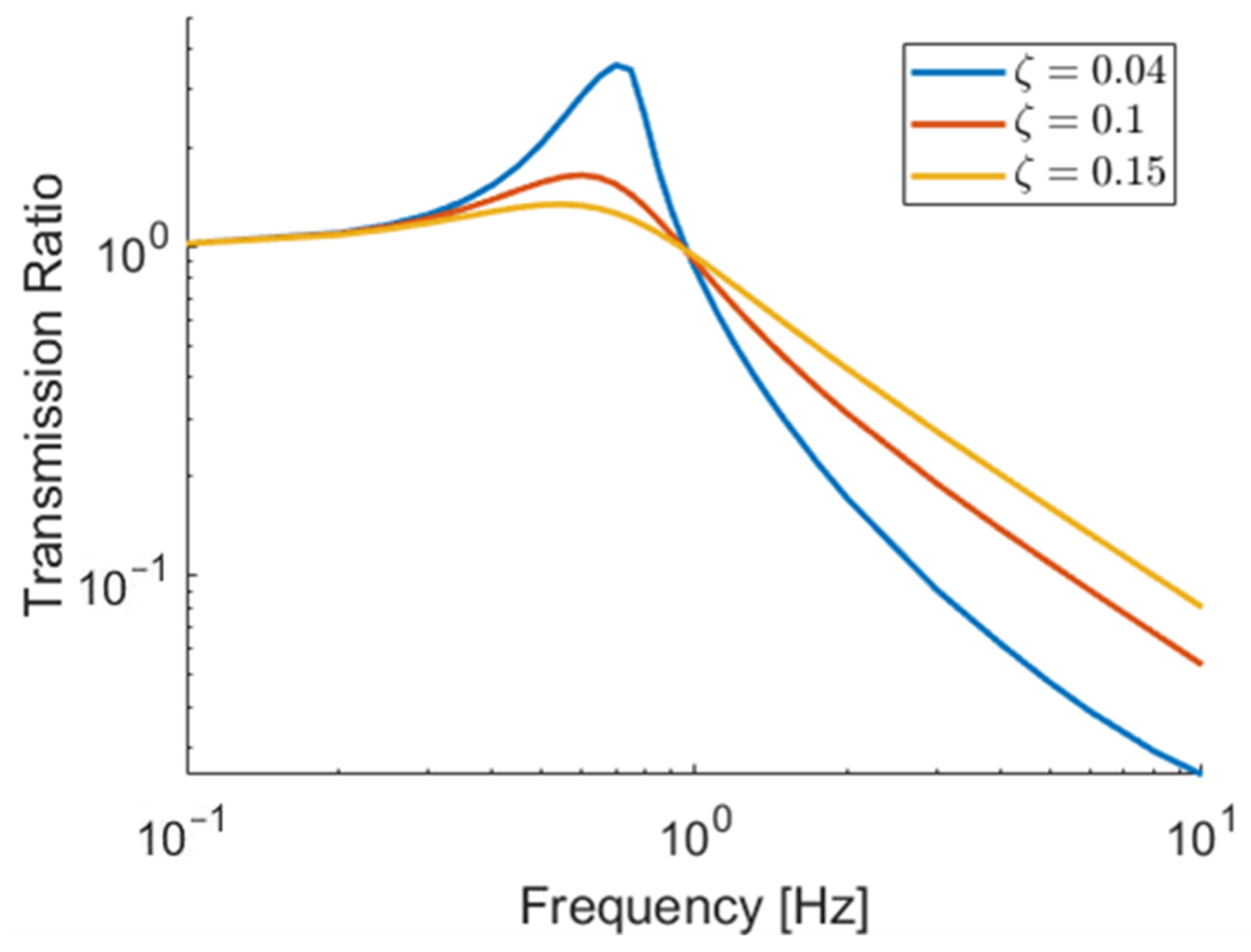
The second performance criterion considers the magnitude of the resonant peak. Using this, the QZS cushion performs considerably worse than the regular cushion. The novel cushion resonates with a peak transmission ratio of around 3.1, while the regular cushion is kept below 1.5 in the amplification zone. Theory suggests that the performance of the QZS cushion according to this criterion could be improved by adding damping to the system. The current prototype does not contain a dedicated damper, but rather relies on friction between internal components to provide a damping effect. Adding a dedicated damper would decrease the peak response of the cushion while maintaining the size of the attenuation region, as demonstrated in Figure 14.
Finally, for the third performance criterion, the ability of the device to attenuate large frequency vibrations within the attenuation zone, the QZS cushion performs better than the foam cushion, largely due to the decreased damping present within the system. The lack of a damper enables the cushion to isolate vibrations within the attenuation zone very quickly. While beneficial, this very large attenuation may be considered less important than the ability of the device to have a smaller resonant peak. It is more beneficial to have a seat that attenuates the entire frequency spectrum well rather than to have areas of large amplification and other areas of large attenuation.
As shown in Figure 9, friction plays a very large role in the dynamics of the overall universal seat, increasing the size of the amplification region and amplifying the cut-off frequency. When compared to the linear system, high friction improves the response of the SDOF system within the linear amplification region, but the performance becomes much worse at frequencies larger than 1.47 Hz. The FBFM models the “sliding” portion of the motion well but does not account for the attenuation seen during the “sticking” phase. Much of the amplification is due to the seat bending under load, as displayed in Figure 7. This additional vibration mode is not included within the mathematical models presented here. When adding the QZS cushion, the “sticking” state is prolonged until much higher frequencies compared to using the foam cushion, since the QZS system attenuates much of the forces acting on mass 2. Figure 15 shows mass 2 “sticking” until nearly 10 Hz.
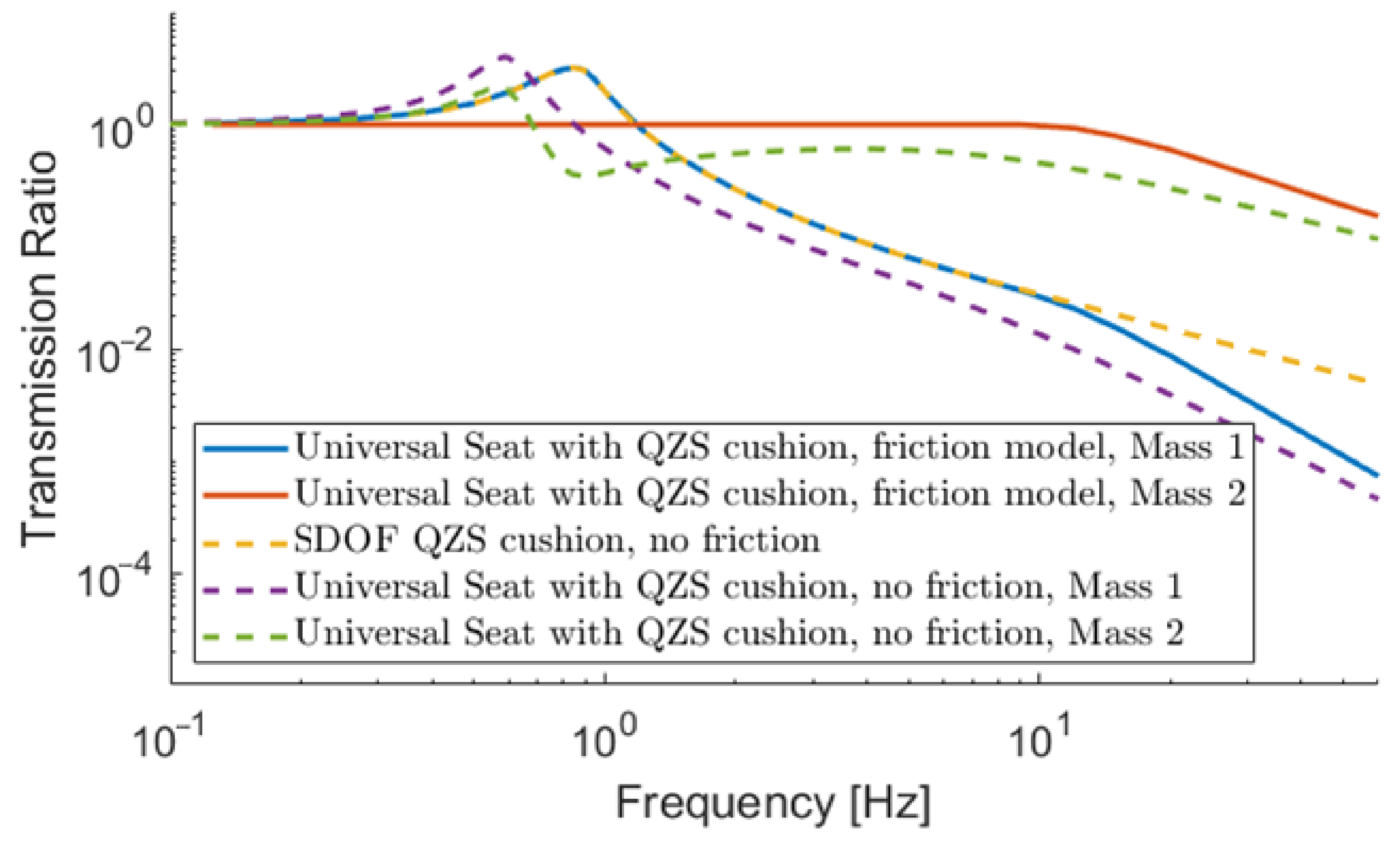
When designing a cushion that is placed on an existing tractor seat, the results suggest that it is important to consider the effects of friction within the existing seat. Within Figure 15, the purple and green lines are analytical transmissibility curves using Equation (4) for mass 1 and 2, respectively, and do not include friction. The blue and red lines show the numerical response with friction, which is the same response as the experimental results in Figure 12 and Figure 13. Without friction, the cushion is expected to enter the attenuation zone at about 0.85 Hz. In reality, the cut-off frequency is 1.18 Hz. Considering ASABE guidelines that suggest that 1.13 Hz is the lowest possible cut-off frequency for a passive air suspension seat, friction transforms the seat from exceeding this guideline to performing slightly worse than it. Both with and without friction, the cut-off is lower than 1.70 Hz, the lower limit for linear steel spring seats. Incidentally, the transmissibility of mass 1 within the 2DOF universal seat with friction is well represented by a single-degree-of-freedom QZS system at low frequencies. Figure 15 shows that the SDOF QZS response is nearly identical to that of the 2DOF model below 9 Hz. This is largely due to the “sticking” state of the tractor seat, which directly transfers excitation forces to the cushion. This is confirmed experimentally in Figure 16, which compares the numerical and experimental transmissibility of mass 2 in the universal seat with the QZS cushion on top. Also shown in Figure 15, in the absence of friction, the 2DOF nonlinear system performs better than the SDOF QZS system. This matches the results of Lu et al., which found that incorporating QZS into the upper stage of a two-layer system improves the overall transmissibility of the system [30].
Due to the very low stiffness of the QZS system and its superior ability to isolate vibrations, it appears at first glance that the universal seat’s suspension does little to improve seat performance. While this is true within the scope of this laboratory study, it is important to consider that the performance of the QZS system decreases at larger excitation amplitudes, while the performance of the universal tractor seat increases. At larger amplitudes, friction plays a smaller role in the dynamic response of the universal seat, allowing its dynamic response to match the linear system more closely. This improved performance is confirmed in Figure 9, where doubling the excitation amplitude results in a larger attenuation region and a smaller peak transmission ratio for the universal seat. On the contrary, as studies have shown, larger excitation amplitudes result in worse performance of a QZS system [21,25]. Since heavy equipment operates on rough ground where complex input frequencies larger than 5 mm are probable, the universal seat’s suspension can better attenuate large amplitude vibrations, while the QZS cushion is able to isolate low-amplitude vibrations down to about 1 Hz. The cushion presented in this paper is perhaps best compared to the work of Guo et al. [15]. Guo et al. describe a seat cushion that contains many individual QZS elements, each using a double-diamond structure. While not built and tested experimentally, the mathematical simulations of the cushion indicate that the natural frequency would be decreased from 13.78 Hz to 3.2 Hz when going from a linear to a QZS structure. The cushion described in the current paper is able to achieve a much smaller natural frequency and therefore is able to isolate lower-frequency vibrations. This work may also be compared to Abuabiah et al. [34], which presents a numerical simulation of a seat suspension composed of a QZS isolator and an air spring. It should be noted that this simulation models a larger replacement seat suspension, not a cushion. Furthermore, this model does not include the presence of friction. The proposed QZS cushion has a lower transmissibility and is more robust against changes in mass compared to the QZS air spring seat suspension model [34]. However, the QZS cushion has a higher natural frequency. The higher natural frequency may be due to the absence of friction in the QZS air spring suspension model.
When utilizing QZS for the application of a seat cushion, it is important to understand the effects of mass on the system’s performance. Assuming an operator mass between 65 kg and 95 kg, a reasonable cushion should be able to accommodate any mass within this range. Using the seat parameters of the QZS cushion and the universal seat within this study, Figure 17 shows that the performance of the seat is robust against large changes in mass. Regardless of mass, the magnitude of the resonant peak remains nearly identical, and the size of the attenuation zone is only increased by small amounts with smaller mass.
The curves in Figure 17 assume that the cushion is tunable so that the resting equilibrium of the mass remains at the point of lowest stiffness. If the cushion is not tuned according to the mass of the operator, the performance of the cushion is much less robust. This suggests that it is critical to tune the device correctly, which is achieved by adjusting the preload on the vertical springs. This is relatively easy to accomplish when there is only a single QZS element but could prove to be more difficult when there are many QZS elements in parallel, such as within the design by Guo et al. [15].
5. Conclusions
The purpose of this paper was to investigate a novel, low-cost seat cushion capable of attenuating low-frequency WBVs transmitted to a vehicle operator. The experimental and mathematical results show that the replacement of a stock foam cushion with a QZS cushion drastically improves the dynamic response of a tractor seat such as the Darby universal tractor seat. This is particularly true when evaluating the performance of the seat using criterion 1, the size of the attenuation zone. In the presence of large amounts of friction, the isolator can attenuate all vibrations at frequencies larger than 1.1 Hz, while the foam cushion attenuates vibrations between 3.4 Hz and 4.1 Hz, as well as frequencies larger than 4.8 Hz. In the absence of friction, the performance is further improved, and the cut-off frequency shifts to 0.85 Hz. These results meet or exceed the ASABE estimates for the best possible performance of a typical passive seat.
When evaluating the performance of the QZS cushion by observing the magnitude of the transmissibility at the resonant frequency, the QZS performs worse than the stock foam cushion. While resonance occurs at very small frequencies below 1 Hz, simulations show that the addition of a dedicated damper to the QZS system would improve the response according to this criterion. Finally, considering the response of the system within the attenuation zone, the QZS cushion performs better than the foam cushion for all frequencies smaller than 10 Hz. The performance of the cushion is not affected by the addition of a thin foam cushion near the top of the device. However, it is important to note that higher acceleration amplitudes, which may be encountered in practical applications, could limit some of the benefits of using QZS.
The performance of the SDOF and 2DOF universal seat is accurately modeled using the FBFM and the accurate acquisition of QZS parameters. Due to the sensitivity of the QZS isolator to vertical stiffness, this needs to be accurately measured using a tensile testing machine rather than relying on the manufacturer’s specifications for the parts. Small inaccuracies, including nonlinearities within the spring itself, are enough to lead to inaccurate modeling of the QZS element.
The present study shows that it is necessary to consider friction as part of a mathematical model when predicting the performance of QZS cushions on tractor seats. Suspensions such as the one on the universal seat can have large amounts of stiction, causing it to perform much worse than predicted by using simple linear modeling techniques. When the tractor seat is “sticking”, the 2DOF system can effectively be modeled as an SDOF QZS system.
Finally, the cushion is shown to be relatively insensitive to changes in mass, assuming that the cushion is accurately tuned to be at the point of lowest stiffness. This is easiest to achieve when there is only a single QZS element, rather than many that need to be tuned simultaneously.
Author Contributions
Conceptualization, M.H. and M.L.O.; formal analysis, J.H.; funding acquisition, M.H. and M.L.O.; investigation, J.H. and M.E.G.; methodology, J.H. and M.H.; project administration, M.H. and M.L.O.; resources, M.H. and M.L.O.; software, J.H.; supervision, M.H. and M.L.O.; validation, J.H.; writing—original draft, J.H.; writing—review and editing, J.H., M.E.G., M.H., and M.L.O. All authors have read and agreed to the published version of the manuscript.
Funding
This research was funded by the Natural Sciences and Engineering Research Council of Canada, grant numbers 390178-10 and 2012-05240, as well as by a Canada First Research Excellence Fund, Food from Thought Commercialization, grant number 499152.
Data Availability Statement
The data are contained in the tables and figures.
Conflicts of Interest
The authors declare no conflicts of interest.
Appendix A

Table A1.
Frequency, displacement amplitude, and root mean square (RMS) acceleration for each vibration profile.
Table A1.
Frequency, displacement amplitude, and root mean square (RMS) acceleration for each vibration profile.
| Frequency (Hz) | 2.5 mm Amplitude | 5 mm Amplitude |
|---|---|---|
| RMS Acceleration (m/s2) | RMS Acceleration (m/s2) | |
| 0.5 | 0.02 | 0.03 |
| 0.6 | 0.03 | 0.05 |
| 0.7 | 0.03 | 0.07 |
| 0.8 | 0.04 | 0.09 |
| 0.9 | 0.06 | 0.11 |
| 1.0 | 0.07 | 0.14 |
| 1.1 | 0.08 | 0.17 |
| 1.2 | 0.10 | 0.20 |
| 1.3 | 0.12 | 0.24 |
| 1.4 | 0.14 | 0.27 |
| 1.5 | 0.16 | 0.31 |
| 1.6 | 0.18 | 0.36 |
| 1.7 | 0.20 | 0.40 |
| 1.8 | 0.23 | 0.45 |
| 1.9 | 0.25 | 0.50 |
| 2.0 | 0.28 | 0.56 |
| 2.1 | 0.31 | 0.62 |
| 2.2 | 0.34 | 0.68 |
| 2.3 | 0.37 | 0.74 |
| 2.4 | 0.40 | 0.80 |
| 2.5 | 0.44 | 0.87 |
| 2.6 | 0.47 | 0.94 |
| 2.7 | 0.51 | 1.02 |
| 2.8 | 0.55 | 1.09 |
| 2.9 | 0.59 | 1.17 |
| 3.0 | 0.63 | 1.26 |
| 3.1 | 0.67 | 1.34 |
| 3.2 | 0.71 | 1.43 |
| 3.3 | 0.76 | 1.52 |
| 3.4 | 0.81 | 1.61 |
| 3.5 | 0.85 | 1.71 |
| 4.0 | 1.12 | 2.23 |
| 4.5 | 1.41 | 2.83 |
| 5.0 | 1.74 | 3.49 |
| 5.5 | 2.11 | 4.22 |
| 6.0 | 2.51 | 5.02 |
| 6.5 | 2.95 | 5.90 |
| 7.0 | 3.42 | 6.84 |
| 7.5 | 3.93 | 7.85 |
| 8.0 | 4.47 | 8.93 |
| 8.5 | 5.04 | 10.08 |
| 9.0 | 5.65 | 11.30 |
References
- Burström, L.; Nilsson, T.; Wahlström, J. Whole-body vibration and the risk of low back pain and sciatica: A systematic review and meta-analysis. Int. Arch. Occup. Environ. Health 2015, 88, 403–418. [Google Scholar] [CrossRef] [PubMed]
- Bovenzi, M.; Pinto, I.; Stacchini, N. Low Back Pain in Port Machinery Operators. J. Sound Vib. 2002, 253, 3–20. [Google Scholar] [CrossRef]
- Costa, N.; Arezes, P.; Melo, R. Effects of occupational vibration exposure on cognitive/motor performance. Int. J. Ind. Ergon. 2014, 44, 654–661. [Google Scholar] [CrossRef]
- ISO 2631-1:1997; Mechanical Vibration and Shock—Evaluation of Human Exposure to Whole-Body Vibration—Part 1: General Requirements. International Organization for Standardization: Geneva, Switzerland, 1997.
- Morioka, M.; Griffin, M.J. Magnitude-dependence of equivalent comfort contours for fore-and-aft, lateral and vertical whole-body vibration. J. Sound Vib. 2006, 298, 755–772. [Google Scholar] [CrossRef] [PubMed]
- Strikeleather, L.F. Operator Seats For Agricultural Equipment. In Proceedings of the ASAE Distinguished Lecture Series, Chicago, IL, USA, 15 December 1981; Volume 7, pp. 1–34. [Google Scholar]
- Wei, C.; Cai, Y.; Zhang, K.; Wang, Z.; Yu, W. Novel Optimal Design Approach for Output-Feedback H inf Control of Vehicle Active Seat-Suspension System. Asian J. Control. 2020, 22, 411–422. [Google Scholar] [CrossRef]
- Fischer, D.; Isermann, R. Mechatronic semi-active and active vehicle suspensions. Control Eng. Pract. 2004, 12, 1353–1367. [Google Scholar] [CrossRef]
- Moosheimer, J.; Waller, H. Reduction of vibrations by bang-bang controlled electrorheological dampers. Arch. Appl. Mech. (Ingenieur Arch.) 2000, 70, 715–737. [Google Scholar] [CrossRef]
- Yao, H.J.; Fu, J.; Yu, M.; Peng, Y.X. Semi-active control of seat suspension with MR damper. J. Phys. Conf. Ser. 2013, 412, 012054. [Google Scholar] [CrossRef]
- Dufner, D.L.; Schick, T.E. New level of seat performance. Resour. Eng. Technol. Sustain. World 2002, 9, 7–8. [Google Scholar]
- Bose Ride System II Delivers New Features and Functionality. Available online: https://www.fleetowner.com/equipment/article/21689971/bose-ride-system-ii-delivers-new-features-and-functionality (accessed on 8 November 2023).
- Le, T.D.; Ahn, K.K. Experimental investigation of a vibration isolation system using negative stiffness structure. Int. J. Mech. Sci. 2013, 70, 99–112. [Google Scholar] [CrossRef]
- Wang, Y.; Li, S.; Cheng, C.; Su, Y. Adaptive control of a vehicle-seat-human coupled model using quasi-zero-stiffness vibration isolator as seat suspension. J. Mech. Sci. Technol 2018, 32, 2973–2985. [Google Scholar] [CrossRef]
- Guo, L.; Wang, X.; Fan, R.-L.; Bi, F. Review on Development of High-Static-Low-Dynamic-Stiffness Seat Cushion Mattress for Vibration Control of Seating Suspension System. Appl. Sci. 2020, 10, 2887. [Google Scholar] [CrossRef]
- Lan, C.C.; Yang, S.A.; Wu, Y.S. Design and experiment of a compact quasi-zero-stiffness isolator capable of a wide range of loads. J. Sound Vib. 2014, 333, 4843–4858. [Google Scholar] [CrossRef]
- Zhou, J.; Wang, X.; Mei, Y. Characteristic analysis of a quasi-zero-stiffness vibration isolator. IOP Conf. Ser. Mater. Sci. Eng. 2018, 397, 012045. [Google Scholar] [CrossRef]
- Le, T.D.; Ahn, K.K. A vibration isolation system in low frequency excitation region using negative stiffness structure for vehicle seat. J. Sound Vib. 2011, 330, 6311–6335. [Google Scholar] [CrossRef]
- Carrella, A.; Brennan, M.; Waters, T.; Shin, K. On the design of a high-static-low-dynamic stiffness isolator using linear mechanical springs and magnets. J. Sound Vib. 2008, 315, 712–720. [Google Scholar] [CrossRef]
- Brennan, M.; Kovacic, I.; Carrella, A.; Waters, T. On the jump-up and jump-down frequencies of the Duffing oscillator. J. Sound Vib. 2008, 318, 1250–1261. [Google Scholar] [CrossRef]
- Carrella, A.; Brennan, M.; Waters, T.; Lopes, V. Force and displacement transmissibility of a nonlinear isolator with high-static-low-dynamic-stiffness. Int. J. Mech. Sci. 2012, 55, 22–29. [Google Scholar] [CrossRef]
- Carrella, A.; Brennan, M.J.; Waters, T.P. Optimization of a Quasi-Zero-Stiffness Isolator. J. Mech. Sci. Technol. 2007, 21, 946–949. [Google Scholar] [CrossRef]
- Carrella, A.; Brennan, M.J.; Waters, T. Static analysis of a passive vibration isolator with quasi-zero-stiffness characteristic. J. Sound Vib. 2007, 301, 678–689. [Google Scholar] [CrossRef]
- Deng, T.; Wen, G.; Ding, H.; Lu, Z.-Q.; Chen, L.-Q. A bio-inspired isolator based on characteristics of quasi-zero stiffness and bird multi-layer neck. Mech. Syst. Signal Process. 2020, 145, 106967. [Google Scholar] [CrossRef]
- Lu, Z.; Yang, T.; Brennan, M.J.; LI, X.; Liu, Z. On the Performance of a Two-Stage Vibration Isolation System Which has Geometrically Nonlinear Stiffness. J. Vib. Acoust. 2014, 136, 064501. [Google Scholar] [CrossRef]
- Mikhailov, V.G. Analysis of models of friction in suspensions of vehicles. J. Frict. Wear. 2014, 35, 149–154. [Google Scholar] [CrossRef]
- Luo, R.; Wu, P.; Luo, J.; Hou, Z.; He, L.; Wang, F. Multi-objective optimization of vehicle seat suspension with friction under random excitation. Proc. Inst. Mech. Eng. Part D J. Automob. Eng. 2022, 236, 2374–2385. [Google Scholar] [CrossRef]
- Karnopp, D. Computer Simulation of Stick-Slip Friction in Mechanical Dynamic Systems. J. Dyn. Syst. Meas. Control 1985, 107, 100–103. [Google Scholar] [CrossRef]
- Hassan, M.; Rogers, R. Friction modelling of preloaded tube contact dynamics. Nucl. Eng. Des. 2005, 235, 2349–2357. [Google Scholar] [CrossRef]
- Lu, Z.; Brennan, M.J.; Yang, T.; Li, X.; Liu, Z. An investigation of a two-stage nonlinear vibration isolation system. J. Sound Vib. 2013, 322, 1456–1464. [Google Scholar] [CrossRef]
- ISO 10326-1:2017; Mechanical Vibration—Laboratory Method for Evaluating Vehicle Seat Vibration. International Organization for Standardization: Geneva, Switzerland, 2017.
- Porteiro, J.L. Spring Design Optimization with Fatigue. Ph.D. Thesis, University of South Florida, Tampa, FL, USA, 1 April 2008. [Google Scholar]
- Wisner, A.; Donnadieu, A.; Berthoz, A. A biomechanical model of man for the study of vehicle seat and suspension. Int. J. Prod. Res. 1964, 3, 285–315. [Google Scholar] [CrossRef]
- Abuabiah, M.; Dabbas, Y.; Herzallah, L.; Alsurakji, I.H.; Assad, M.; Plapper, P. Analytical Study on the Low-Frequency Vibrations Isolation System for Vehicle’s Seats Using Quasi-Zero-Stiffness Isolator. Appl. Sci. 2022, 12, 2418. [Google Scholar] [CrossRef]
Figure 1.
The model of a two-degree-of-freedom system consisting of nonlinear stiffness elements.

Figure 2.
The stiffness of a High-Static Low-Dynamic (HSLD) system when tuned to have localized positive, negative, and quasi-zero stiffness (QZS).
Figure 2.
The stiffness of a High-Static Low-Dynamic (HSLD) system when tuned to have localized positive, negative, and quasi-zero stiffness (QZS).

Figure 3.
Negative stiffness oblique spring mechanism.

Figure 4.
Overall experimental setup of universal tractor seat with quasi-zero stiffness cushion on top.
Figure 4.
Overall experimental setup of universal tractor seat with quasi-zero stiffness cushion on top.

Figure 5.
The internal mechanism of the novel quasi-zero stiffness cushion with a foam pad on top.

Figure 6.
A force–displacement plot of the universal tractor seat as a single-degree-of-freedom system. (a) The Instron applies its force near the front of the seat; (b) the Instron applies its force near the back of the seat. In each plot, the green line is fit to the preload portion of the plot and the purple line to the main stroke of the seat. When a mass is placed on the seat, the seat vibrates entirely within the ”Seat Stroke” region.

Figure 7.
Diagram of stock universal tractor seat, containing two potential degrees of freedom.

Figure 8.
Spring stiffness of springs within quasi-zero stiffness cushion. (a) Spring stiffness of vertical springs approximated by line of best fit; (b) Spring stiffness of ten oblique springs in parallel approximated by line of best fit.
Figure 8.
Spring stiffness of springs within quasi-zero stiffness cushion. (a) Spring stiffness of vertical springs approximated by line of best fit; (b) Spring stiffness of ten oblique springs in parallel approximated by line of best fit.

Figure 9.
The experimental dynamic response of the universal tractor seat compared to the expected linear response and the numerical simulation with the Force Balance Friction Model. In all cases, m = 81.9 kg, ζ = 0.4, k = 3420 m/N, and = 0.001 m/s.
Figure 9.
The experimental dynamic response of the universal tractor seat compared to the expected linear response and the numerical simulation with the Force Balance Friction Model. In all cases, m = 81.9 kg, ζ = 0.4, k = 3420 m/N, and = 0.001 m/s.

Figure 10.
Universal tractor seat with quasi-zero stiffness and foam cushion on top of it.

Figure 11.
Comparison of the experimental, analytical, and numerical results for the quasi-zero stiffness (QZS) cushion. The analytical response of a similar linear system is included for reference. For all plots, the mass, vertical stiffness, and damping are identical. In the case of the QZS system, tuned oblique springs are added.

Figure 12.
The response of the overall universal seat with a regular cushion and the quasi-zero stiffness (QZS) cushion.
Figure 12.
The response of the overall universal seat with a regular cushion and the quasi-zero stiffness (QZS) cushion.

Figure 13.
Dynamic response of the one-inch polyurethane foam pad used on the quasi-zero stiffness (QZS) cushion between 0.5 and 9 Hz.
Figure 13.
Dynamic response of the one-inch polyurethane foam pad used on the quasi-zero stiffness (QZS) cushion between 0.5 and 9 Hz.

Figure 14.
Effect of increasing viscous damping (ζ) within quasi-zero stiffness cushion.

Figure 15.
Theoretical response of universal seat and quasi-zero stiffness (QZS) cushion with and without friction.
Figure 15.
Theoretical response of universal seat and quasi-zero stiffness (QZS) cushion with and without friction.

Figure 16.
Mass 2 transmissibility within the universal seat in combination with the quasi-zero stiffness (QZS) cushion.
Figure 16.
Mass 2 transmissibility within the universal seat in combination with the quasi-zero stiffness (QZS) cushion.

Figure 17.
The effects of changing mass on the universal seat with the quasi-zero stiffness (QZS) cushion, assuming that the cushion is tuned to the point of lowest stiffness.
Figure 17.
The effects of changing mass on the universal seat with the quasi-zero stiffness (QZS) cushion, assuming that the cushion is tuned to the point of lowest stiffness.

Table 1.
Physical properties of the quasi-zero stiffness (QZS) cushion, as well as the parameters under which it is tested.
Table 1.
Physical properties of the quasi-zero stiffness (QZS) cushion, as well as the parameters under which it is tested.
| Property | QZS Cushion |
|---|---|
| 22,840 Nm | |
| 12,152 Nm | |
| 0.0025 m | |
| 81.90 kg | |
| 5% | |
| 0.063 m | |
| 0.1178 m |
Disclaimer/Publisher’s Note: The statements, opinions and data contained in all publications are solely those of the individual author(s) and contributor(s) and not of MDPI and/or the editor(s). MDPI and/or the editor(s) disclaim responsibility for any injury to people or property resulting from any ideas, methods, instructions or products referred to in the content. |
© 2024 by the authors. Licensee MDPI, Basel, Switzerland. This article is an open access article distributed under the terms and conditions of the Creative Commons Attribution (CC BY) license (https://creativecommons.org/licenses/by/4.0/).
Share and Cite
MDPI and ACS Style
Habegger, J.; Govers, M.E.; Hassan, M.; Oliver, M.L. The Development of a High-Static Low-Dynamic Cushion for a Seat Containing Large Amounts of Friction. Vibration 2024, 7, 388-406. https://doi.org/10.3390/vibration7020020
AMA Style
Habegger J, Govers ME, Hassan M, Oliver ML. The Development of a High-Static Low-Dynamic Cushion for a Seat Containing Large Amounts of Friction. Vibration. 2024; 7(2):388-406. https://doi.org/10.3390/vibration7020020
Chicago/Turabian StyleHabegger, Janik, Megan E. Govers, Marwan Hassan, and Michele L. Oliver. 2024. "The Development of a High-Static Low-Dynamic Cushion for a Seat Containing Large Amounts of Friction" Vibration 7, no. 2: 388-406. https://doi.org/10.3390/vibration7020020