The Performance of an ASHP System Using Waste Air to Recover Heat Energy in a Subway System


School of Computing, Engineering and Built Environment, Glasgow Caledonian University, Cowcaddens Road Glasgow, G4 0BA Scotland, UK
*
Author to whom correspondence should be addressed.
Clean Technol. 2019, 1(1), 154-163; https://doi.org/10.3390/cleantechnol1010011
Submission received: 2 May 2019
/
Revised: 17 July 2019
/
Accepted: 22 July 2019
/
Published: 29 July 2019
Abstract
:In this short communication, we demonstrate that the performance of a typical air source heat pump (ASHP), exploiting a relatively stable air temperature within a subway environment, is high, even during the peak heating months. After a nine-month operational run, the coefficient of performance is demonstrated to be 3.5. The design and installation difficulties are stated together with the lessons learnt following this trial. The actual energy and carbon savings are discussed.
1. Introduction
Scarcity of energy resources has been a global challenge for many years. The need to find alternative sources to replace conventional fuel is now becoming more important than ever due to climate change concerns [1]. In response to such concerns, the UK government has set ambitious targets to fully decarbonize heating by 2050 [2]. Additionally, the Scottish Government has set the target of 100% equivalent of Scotland’s gross annual electricity consumption to be supplied from renewable sources by 2020 [3] and a further 11% of the heat to be supplied by renewable sources during the same time frame. One of the means for the latter, amongst others, is the use of heat pumps [4].
Air source heat pump (ASHP) systems have shown potential to reduce energy consumption, and as a result CO2 reduction of more than 50% compared to conventional heating systems (electricity, oil, gas) can be achieved [5]. They operate based on the same principle as a water source heat pump. The only difference is the heat source element, air, which is being absorbed from the ASHP’s outdoor unit (condenser). The produced heat can then be utilised through radiators, underfloor heating systems, or warm air convectors, and furthermore, to provide domestic hot water (DHW). There are two types of ASHPs—“air to air” and “air to water”. Both use air as a method of transporting heat energy from one medium to another, from the “source” to the “sink”. Water may be used in conjunction with air to achieve adequate heat transfer within an ASHP. Used effectively, ASHPs work much more efficiently than traditional boiler systems at lower temperatures, and therefore are better suited to underfloor heating, producing hot water or for the introduction of warm air to heat a house.
This paper reports the outcome of an ASHP trial installation carried out in the Glasgow Subway system. The air stored in cavities below ground can be heated by the pressure and heat within the earth’s surface and as such can be used as an effective method of sourcing low-grade geothermal heat. The extracted heat (in our case from the recycled air within the tunnels) is transferred to the water, which is piped inside the building for heating/cooling and for domestic hot water. A design for such a system was recently presented by [6]. The appropriateness of underground railway systems for the use of ground-source heat pumps was reviewed by [7]. Several feasibility studies demonstrated that an ASHP can be positioned within such a closed, yet well ventilated environment with promising performances [8,9]. The latter study also highlighted the lessons learnt following installation and the potential for this system to be scaled up in similar environments.
2. ASHP Installation
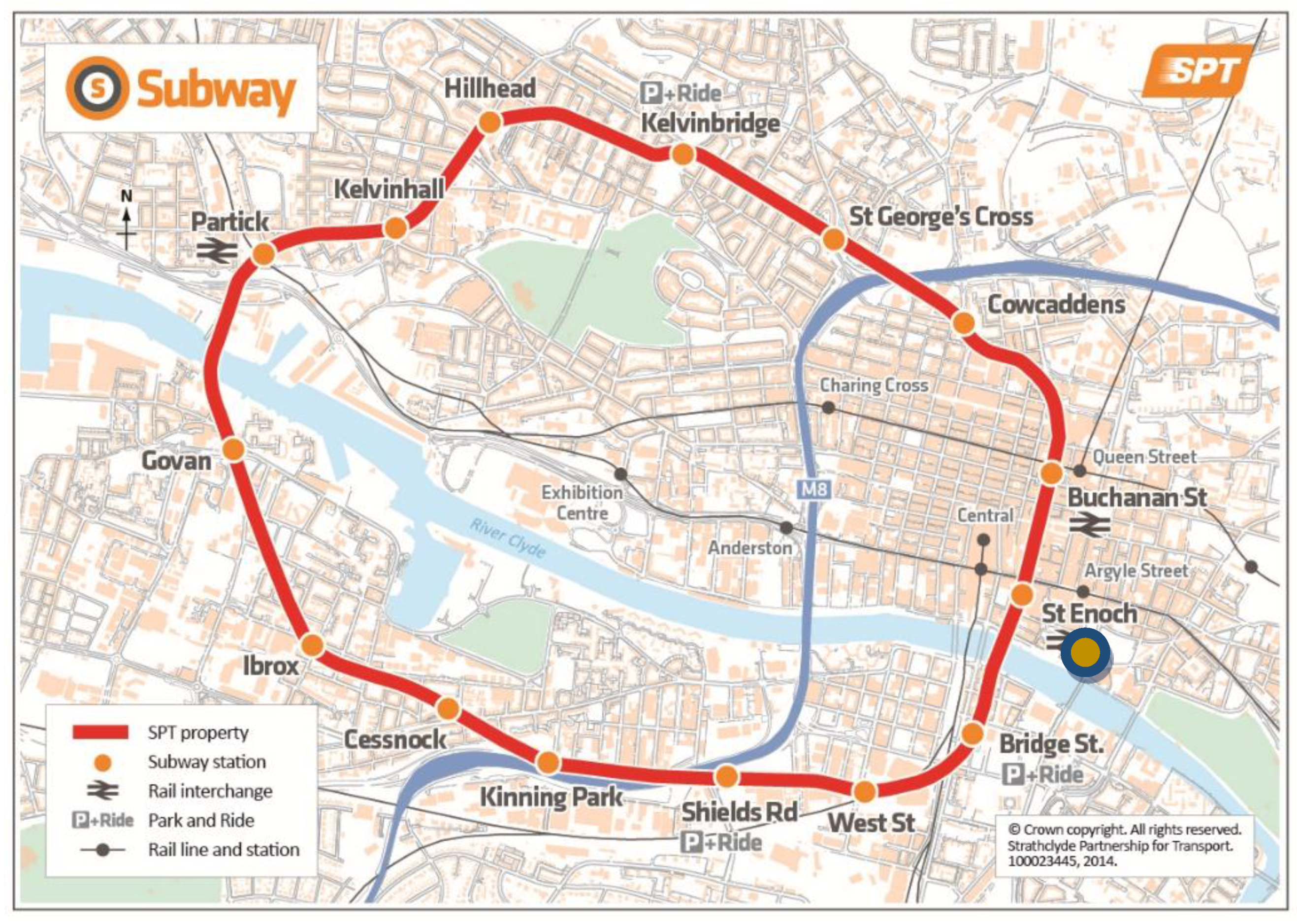
Strathclyde Partnership for Transport (SPT) who operates the Glasgow Subway, were keen on finding ways to exploit its wasted resources within the underground system. They already use wastewater via a water source heat pump (WSHP) in the northern part of the subway at St George’s cross Station, providing heat and domestic hot water (DHW) for the Station’s ticket booth [9]. Due to the nonexistence of water flux in the southern part of the subway system (to the south of river Clyde—Figure 1), the ASHP trial installation was focused on the following five stations: Bridge Street, West Street, Shields Road, Cessnock and Ibrox. Based on the distance from the “source” (the point where the condenser would be positioned) to the “sink” (the final heated area-station’s ticket booth) the Bridge Street station was chosen, since it had one of the shortest distances (15 m). This short distance would lead to minimum interference in the subway system, with the least amount of pipe work, resulting in little heat loss from the trial installation. The available space for a heat pump was identified at platform level where the condenser could fit without disturbing the subway’s kinematic envelope and without cluttering the station platform. The SPT required the condenser not to be visible to the passengers, therefore it was decided to position it below the stairs at the platform level, which is only 10 m below the ground level (Figure 2).
The relatively confined Station platform volume (820 m3) in relation to the recurrent air exchange (15.8 m3/h) [10], due to constant train movements and low platform depth, allows for a constant natural air flow at platform level. Based on previous surveys undertaken by the SPT, the air quality at the platform level was similar to the outdoor environment; therefore, no additional air quality monitoring was undertaken. The air temperature in the subway was monitored over a period of 15 months and found to be relatively stable, even during the cold winter months. This was expected to enable the condenser to operate without using its full power. When the ambient temperature reaches values close to zero (0) degrees Celsius or below, frost is formed on the outdoor condenser unit. This layer of ice acts as an insulating layer which reduces the air flow. This dramatically reduces the system efficiency and takes time and energy to defrost the unit. The resulting increase in the compressor work translates into higher energy input. The lack of such conditions in this underground environment was hypothesised to lead to low levels of ASHP energy intake, compared with a typical installation operating in an outdoor environment, thus resulting in a higher performance factor.
In order for this to work at a high efficiency, two conditions need to be present: Relatively stable and warm air temperatures, and sufficient air movement to ensure continuous operability. As discussed above, both conditions were met at all fifteen stations due to the absence of any obstacles between the platform and the outside atmosphere. Although no forced air ventilation system exists in any location within the tunnel system, the air is constantly in motion, and at relatively high speeds due to the movement of trains as well as from the natural air movement between the platform and the surrounding atmosphere in the concourse level. The trains, which pass by each station at approximately every 5 min, create the “piston effect” which enhances the air flow further at the platform level.
According to Banks [11], the efficiency of a heat pump can be defined as the ratio of heat delivered (H) at elevated temperature (T1) to work performed by the compressor (W). The maximum efficiency is:
The efficiency of the system depends on the temperature at the delivery side “sink” (T1) and the “source” side (T2). In all modern heat exchangers (heat pumps) the compressor is powered by electricity, so by replacing the W by P (electrical power input) we have the efficiency of a heat pump, which is usually referred to as its coefficient of performance (CoP), where:
The Bridge Street station’s heat load was calculated at 5.0 kW; therefore, a system to provide heating/cooling and domestic hot water (DHW) was proposed [10]. A basic design for this pilot installation was undertaken and an ASHP of 9 kW output was required to meet this subway station’s heating/cooling and domestic hot water demand (Table 1).
The heat pump was installed at the end of 2015. And the system has been set up to operate automatically from 5:30 am to 11:00 pm (the subway’s operational hours) every day. It is a low grade heating system, with the water temperature within the radiators being around 50 °C. The radiators comprise four fan coil units where the water circulates into the radiators through a heat exchanger inside the fan coils to generate hot air. Their operational time depends on the temperature that has been set on the thermostat located within the ticket office. The system has been designed based on an average office temperature of 21 °C (range 19–23 °C).
The system was remotely monitored with a heat meter (Figure 3 and Figure 4) in order to undertake readings with regards to its performance (energy input (in kW) vs. heat energy output (in kW)).
A major concern during this installation was to satisfy all of SPT’s requirements with regards to the safety of the subway. The design had to take into account details such as the materials, all of which had to comply with the fire regulation guidelines. The kinematic envelope of the subway system should not be disrupted, thus all works during the installation should respect the outline of the space occupied by the trains when in motion. Tests were undertaken before the final installation to satisfy these requirements (Figure 5 and Figure 6). The pipe route had to be designed and finally installed in such way to avoid any possible vandalism by the passengers.
3. Results and Lessons Learnt
This installed system is a conventional ASHP that, unlike a standard installation, utilizes the air from within the built confines of the subway platform, as opposed to the outside air. Given the enclosed nature of the platform/tunnel area, a permanent air draft with a year-round mean temperature of 16.7 degrees Celsius and a mean humidity of 68.9% feed the unit. The air flow and pressure at platform level had a mean value of 15.82 m3/h and 1.5 Pa respectively [10]. To obtain the maximum output of trains’ movements and raise the air input, the condenser unit was positioned at a 30 degree angle to the wall under the stairs (Figure 7). This was empirically derived, after trying out various positions to check their efficiency.
According to Equation (2), a 3.5 kW heat energy output for 1 kW energy input was measured via the energy meter during the first operational month of the ASHP (Figure 8).
Due to the enclosed environment where the condenser was positioned (outdoor heat pump unit at the platform level—Figure 3), quarterly inspections were appointed for the first operating year. A maintenance contractor was appointed to inspect and monitor the heat pump to identify any possible issues or malfunctions and address them accordingly. Previous surveys undertaken from the SPT, displayed satisfactory air quality within the subway system. However, the authors wanted to study the condenser’s physical condition and whether that would affect the system’s performance during the monitoring period. The difference, in relation to visiting the unit, compared to a typical installation, was that it could be approached only within a short time frame when the trains stopped operating (from 1:00 a.m. to 5:00 a.m.).
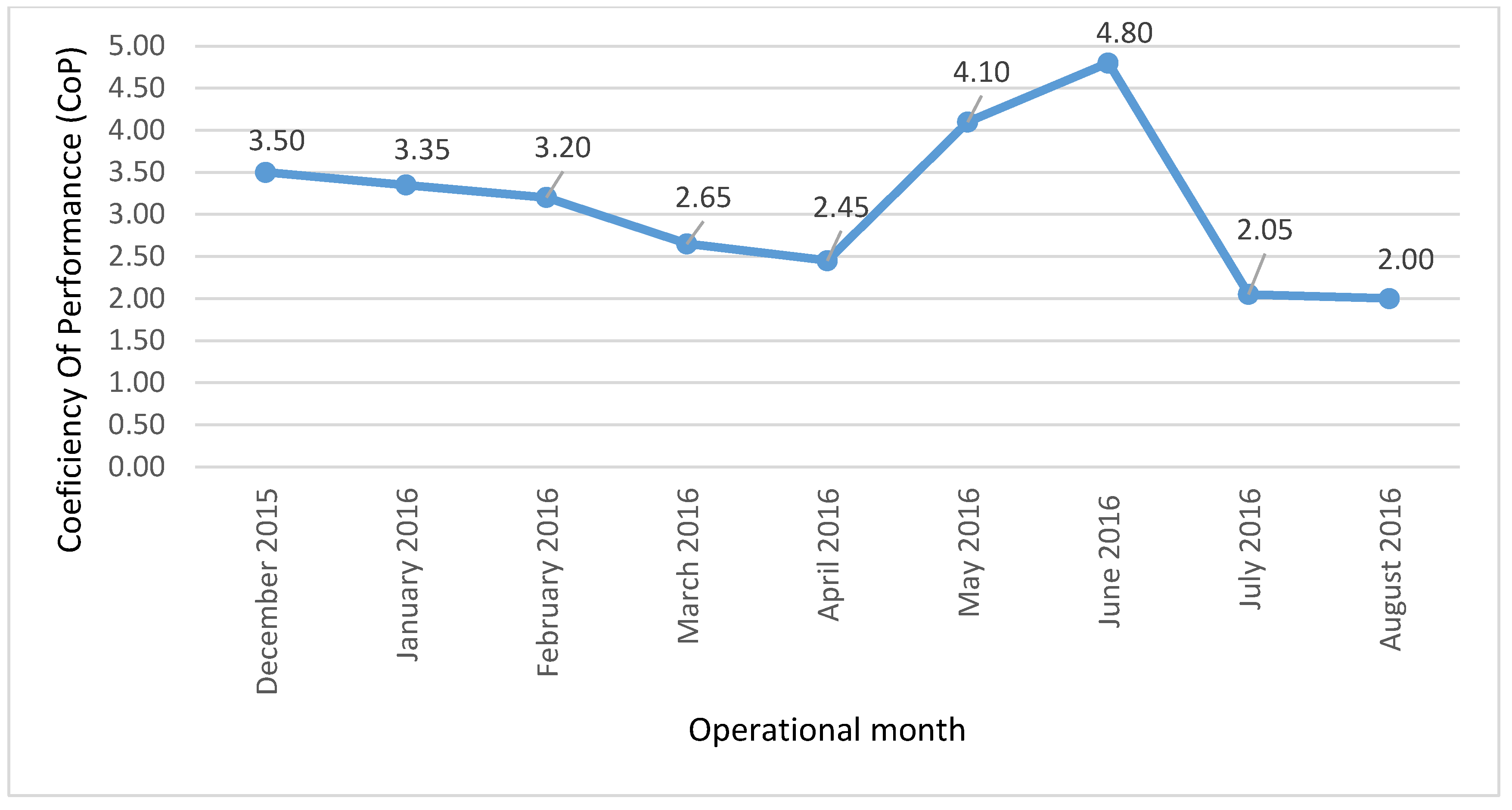
With the heat energy monitoring system, the actual output of the ASHP was recorded as follows (Figure 9).
The first three maintenance visits (for the first nine months of operation), took place in January, April and August 2016. Those visits displayed that the levels of dirt on the condenser, according to the maintenance contractor, were higher but within acceptable levels compared to similar units installed in an outdoor environment.
The unit was cleaned during those visits; the fins were also checked, and the operation of the ASHP continued without any major issues.
After the two first maintenance periods, (January and April 2016) the efficiency of the system was improved compared to the overall monitoring period (Figure 9). This was not visible in February due to the high demand for hot water during winter time, but it is shown clearly in May, when the hot water demand was reduced (late spring time). In August, during the third maintenance inspection, the condenser’s louvers were filled with dust, resulting in poor air intake and circulation. Therefore, the performance dropped for those two months (July and August). Unfortunately, this was identified two months after it occurred, which resulted in a low performance ratio for that period. This was due to other civil works undertaken in that area for the subway’s modernization, which had not been assessed for their effect on the ASHP’s operation and performance. Based on measurements with regards to the energy input, the previous heating system (electrically fired radiators) took 8.07 kW considering that the heating period was 16 h/day. An energy logger (Fluke 1730), was used to measure the electricity input for the old heating circuit for a week. The total energy consumption for the five radiators over that period was 0.904 MWh (0.904 MWh = 904 KWh/7 days = 129.14 KWh per day. 129.14 kWh/16 h = 8.07 KW) [9]. With the readings from the ASHP’s energy monitoring system, it is concluded that the energy input for this station has been reduced by almost 70%. The reduced CO2 emissions are directly related to the electric energy input (Table 2).
During the monitoring period, the ASHP operated only in heating mode, for the simple reason that there was no cooling demand. Therefore, no data have been captured for this latter mode.
4. Conclusions
The aim of this research was to identify which areas within the subway’s tunnel environment are most suitable for future locations of ASHP installations. In the quest for finding a solution to generating renewable heat for SPT’s own buildings or potentially for commercial use, a trial ASHP installation within a confined environment was undertaken. After a survey of 15 months aiming to identify, observe and measure the air flow, humidity and pressure, a trial 9 kW output ASHP installation was completed in 2015 and monitored for nine months to describe the system performance and assess the outputs.
The air absorption from the condenser is negligible compared to the platform’s air volume which circulates within the two tunnels, and no air balance issues were observed during the monitoring period, probably due to the small size of the heat pump and the station’s natural, non-forced ventilation system.
The unit never operated in the “defrost cycle,” due to the relatively stable temperature within the platform level (15.2 °C) [10], even during the cold Glaswegian winter months. This resulted in a higher systems efficiency, reducing the compressor’s work, thus keeping the energy input low at all times.
At the Bridge Street Station during the first operational month, there was a 3.5 kW heat energy output for 1 kW energy input. This demonstrated that the energy cost and the carbon footprint of this station have been reduced substantially compared to the old electrically fired heating system.
The maintenance cost for this system is approximately £200/visit (after the first 4 visits an annual inspection of the system is required). The payback period for the Bridge Street Station ASHP’s system, taking into account the actual equipment and installation cost, is expected to be nine years. However, the inspection of this system was not easy compared to a typical ASHP setup, due to the position of the condenser, which was located at platform level. During prescheduled maintenance inspections the condenser’s louvers were filled with dust, resulting in poor air intake and air circulation. Therefore, the performance dropped for two months. Even with some minor issues, the ASHP’s output performance indicated (for the first nine months of operation) an average performance ratio of 3 (CoP) comprising all heating and domestic hot water needs. In a typical ASHP setup, inspecting the condenser is something that can be accommodated with ease, as can cleaning when necessary.
The cooling option of this heat pump is expected to assist in maintaining the station’s plant room temperature, where cooling is necessary to secure an undisrupted electrical performance of the train’s infrastructure.
Author Contributions
Conceptualisation, K.N., N.H., R.E.; methodology, K.N., N.H., R.E.; investigation, resources, K.N.; writing-original draft preparation, K.N.; writing-review and editing, E.R., N.H., B.A.
Funding
This research was funded by the Knowledge Transfer Partnership (KTP) grant number: KTP0009342.
Acknowledgments
The authors would like to thank the following from the SPT: Gordon McLennan, Charles Hoskins and Stuart McMillan, whose belief in the approach described herein made it possible for us to carry out the work.
Conflicts of Interest
The authors declare no conflict of interest. The funders had no role in the design of the study, in the collection, analysis, or interpretation of data, in the writing of the manuscript or in the decision to publish the results.
References
- Ürge-Vorsatz, D.; Cabeza, L.F.; Serrano, S.; Barreneche, C.; Petrichenko, K. Heating and cooling energy trends and drivers in buildings. Renew. Sustain. Energy Rev. 2015, 41, 85–98. [Google Scholar] [CrossRef] [Green Version]
- DECC. The Future of Heating: Meeting the Challenge. 2013. Available online: https://assets.publishing.service.gov.uk/government/uploads/system/uploads/attachment_data/file/190149/16_04-DECC-The_Future_of_Heating_Accessible-10.pdf (accessed on 10 August 2018).
- Scottish Government. Renewable and Low Carbon Energy Policy. Available online: https://www.gov.scot/policies/renewable-and-low-carbon-energy/ (accessed on 12 July 2019).
- Scottish Government. 2020 Routemap for Renewable Energy in Scotland—Updated. 2013. Available online: www.gov.scot/resource/0044/00441628.pdf (accessed on 9 August 2018).
- US Department of Energy. Heat Pumps. Available online: http://energy.gov/energysaver/articles/air-source-heat-pumps (accessed on 8 August 2018).
- Chai, Y.; Sun, T.; Han, H.; Cao, F.; Liu, Y. Modularly design for waste heat recovery system in subway based on Air Source Heat Pump. Procedia Eng. 2017, 205, 273–280. [Google Scholar] [CrossRef]
- Revesz, A.; Chaer, I.; Thompson, J.; Mavroulidou, M.; Gunn, M.; Maidment, G. Ground source heat pumps and their interactions with underground railway tunnels in an urban environment: A review. Appl. Therm. Eng. 2016, 93, 147–154. [Google Scholar] [CrossRef]
- Davies, G.; Boot-Handford, N.; Curry, D.; Dennis, W.; Ajileye, A.; Revesz, A.; Maidment, G. Combining cooling of underground railways with heat recovery and reuse. Sustain. Cities Soc. 2019, 45, 543–552. [Google Scholar] [CrossRef]
- Ninikas, K.; Hytiris, N.; Emmanuel, R.; Aaen, B. Heat energy from a shallow geothermal system in Glasgow, UK: Performance evaluation design. Environ. Geotech. 2017. [Google Scholar] [CrossRef]
- Ninikas, K.; Hytiris, N.; Emmanuel, R.; Aaen, B.; Younger, P.L. Heat recovery from air in underground transport tunnels. Renew. Energy 2016, 96, 843–849. [Google Scholar] [CrossRef] [Green Version]
- Banks, D. An Introduction to Thermogeology: Ground Source Heating and Cooling, 2nd ed.; Wiley-Blackwell, John Willey & Sons Ltd.: Hoboken, NJ, USA, 2012; p. 94. [Google Scholar]
Figure 1.
The Glasgow subway system. (Adapted from Strathclyde Partnership for Transport—SPT).

Figure 2.
The air source heat pump (ASHP) location at the Bridge Street station’s platform level.

Figure 3.
The ASHP system’s layout.

Figure 4.
The compact indoor unit of the heat pump and the energy meter (in red circle).

Figure 5.
Pipe held in place for route scanning.

Figure 6.
The route scanner device, to identify any disruption in the train’s path due to the ASHP’s installation.
Figure 6.
The route scanner device, to identify any disruption in the train’s path due to the ASHP’s installation.

Figure 7.
The condenser under the stairs at platform level, positioned on an angle.

Figure 8.
First month performance of ASHP at Bridge Street Station. Blue: heat pump supply (kW); Red: heat pump output (kW).
Figure 8.
First month performance of ASHP at Bridge Street Station. Blue: heat pump supply (kW); Red: heat pump output (kW).

Figure 9.
Coefficiency of Performance (CoP) of the ASHP at the Bridge Street Station for the first 9 months.
Figure 9.
Coefficiency of Performance (CoP) of the ASHP at the Bridge Street Station for the first 9 months.

Figure 10.
Buchannan Street Station’s ASHP below the stairs at platform level.


Table 1.
Air Source Heat Pump (ASHP) design parameters.
| Description | Characteristics | Unit |
|---|---|---|
| Air source heat pump (“Air to water”) | 9 | kW |
| Heating capacity (At 45 °C flow temperature and 7 °C ambient temperature) | 8.8 | kW |
| 30.000 | BTU | |
| Cooling capacity (At 45 °C flow temperature and 7 °C ambient temperature) | 7.5 | kW |
| 25.500 | BTU | |
| COP (At 45 °C flow temperature and 7 °C ambient temperature) | 2.8 | W/W |
| Power supply: Volt/Phase/Hz | 230/1/50 | - |
| Compressor type/number | Rotary/1 | - |
| Noise | 50 | dB(A) |
| Refrigerant liquid | R410 | - |
| Dimensions: Length/Width/Height (max) | 1400/600/900 | mm |
| MCS * approved | Yes | - |
Note: *—Microgeneration Certification Scheme (MCS) is a UK-wide nationally recognised quality assurance scheme, supported by the Department for Business, Energy and Industrial Strategy.
Table 2.
Bridge Street Station’s old and new system’s output comparison.
| Heating | Energy Input | Heat Energy Output | Cost/Power | Cost/Day (18h) | Cost/9 Months (270 d) | Carbon Dioxide Factor (kgCO2/kWh) | By-Product |
|---|---|---|---|---|---|---|---|
| kW | kW | £/kWh | £ | £ | Kg | ||
| Old: 5 electric radiators (2kW) | 10 | 10 | 10 × 0.12 = 1.2 | 1.2 × 18 = 21.6 | 5832 | 0.49 | None |
| New: ASHP | 3 | 9 | 3 × 0.12 = 0.36 | 0.36 × 18 = 6.48 | 1749 | 0.14 | Cooling |
© 2019 by the authors. Licensee MDPI, Basel, Switzerland. This article is an open access article distributed under the terms and conditions of the Creative Commons Attribution (CC BY) license (http://creativecommons.org/licenses/by/4.0/).
Share and Cite
MDPI and ACS Style
Ninikas, K.; Hytiris, N.; Emmanuel, R.; Aaen, B. The Performance of an ASHP System Using Waste Air to Recover Heat Energy in a Subway System. Clean Technol. 2019, 1, 154-163. https://doi.org/10.3390/cleantechnol1010011
AMA Style
Ninikas K, Hytiris N, Emmanuel R, Aaen B. The Performance of an ASHP System Using Waste Air to Recover Heat Energy in a Subway System. Clean Technologies. 2019; 1(1):154-163. https://doi.org/10.3390/cleantechnol1010011
Chicago/Turabian StyleNinikas, Konstantinos, Nicholas Hytiris, Rohinton Emmanuel, and Bjorn Aaen. 2019. "The Performance of an ASHP System Using Waste Air to Recover Heat Energy in a Subway System" Clean Technologies 1, no. 1: 154-163. https://doi.org/10.3390/cleantechnol1010011