

Adsorption Cooler Design, Dynamic Modeling, and Performance Analyses


TEMA—Centre for Mechanical Technology and Automation, Department of Mechanical Engineering, University of Aveiro, 3810-193 Aveiro, Portugal
*
Author to whom correspondence should be addressed.
Clean Technol. 2022, 4(4), 1152-1161; https://doi.org/10.3390/cleantechnol4040070
Submission received: 6 June 2022
/
Revised: 8 August 2022
/
Accepted: 26 September 2022
/
Published: 3 November 2022
(This article belongs to the Special Issue Synergistic Technologies to Advance in Sustainable Refrigeration)
Abstract
:This paper presents an adsorption cooler (AC) driven by the surplus heat of a solar thermal domestic hot water system to provide cooling to residential buildings. A cylindrical tube adsorber using granular silica gel as adsorbent and water as adsorbate was considered. The AC was modelled using a two-dimensional distributed parameter model implemented in previous adsorption heating and cooling studies. The performance coefficients of the resultant thermally driven cooling system were obtained for a broad range of working conditions. The thermally driven AC was found to have coefficient of performance (COP) of 0.5 and a specific cooling power (SCP) of 44 W·kg−1 when considering condenser, evaporator, and regeneration temperatures of 30 °C, 15 °C, and 70 °C, respectively. Moreover, the results showed that the AC could be used for refrigeration purposes at temperatures as low as 2 °C and that it could also operate during hotter days under temperatures of 42 °C.
1. Introduction
Heating and cooling stand as the biggest energy end-use sector in Europe, accounting for 51% of the EU’s total energy consumption in 2019, with approximately 75% being obtained from burning fossil fuels [1]. During recent years, the focus is on including renewables in the energy sector and increasing its share. However, considering residential and industrial buildings and processes, the heating and cooling sector is more harmful to the environment than the energy sector itself. More effort must be made in diminishing the negative impacts of thermal energy needs and in moving towards the achievement of the key energy goals set for the next decade through the introduction of new technologies and the improvement of those that are already available. Given that adsorption cooling (AC) can be driven by renewable energy sources and waste heat, this technology can play a significant role in the achievement of these goals. Unlike common vapour compression refrigerators and coolers, AC can work with zero global warming potential (GWP) refrigerants such as water, which is environmentally friendly, abundant in nature, and causes no harm in case of leakages. The low COP is usually pointed out as the major disadvantage of AC technologies. However, ACs are directly driven by thermal energy, meaning that no energy is lost in producing electricity and compensating the heat to work energy conversion efficiency. Due to this, a fairer comparison criterion is required than just comparing the numerical values of adsorption and vapour compression systems’ COPs [2]. Moreover, when using thermal energy that is freely obtained, the coefficient of performance (COP) loses its importance. Developing systems that can use waste heat to regenerate AC would lead to the elimination of their major disadvantage; that is, the low COP. However, if the thermal to electric energy conversion efficiency is considered (η ≈ 40% in 2019), the COP for vapour compression systems is much lower than commonly reported, which means that AC systems’ COP is not a real disadvantage. It is common for the need for cooling to occur when excess heat is available, such as solar heat, ambient heat, waste heat from machine operation, and industrial processes. Using the surplus of thermal energy, it is possible to thermally drive ACs. Unlike conventional refrigerators and coolers that require electricity to function, ACs can work with excess thermal energy, resorting to just tiny batteries to power the control electronics and drive small circulation pumps.
The European Union has recently reinforced support for heat pump technologies, and it is important to make use of the financial incentives, decided on by policy makers, to carry out further research on AHP technology to minimize its well-identified disadvantages and improve its technology readiness level (TRL). Several studies on adsorption systems have been carried out. These studies are commonly focused on five aspects of adsorption systems: selection of adsorbent–adsorbate working pairs (e.g., [3,4]), development of new adsorbent materials (e.g., [5,6,7,8,9]), adsorbent materials’ physical and thermodynamic properties (e.g., [10,11,12]), adsorber configurations (e.g., [13,14,15,16]), and operating conditions (e.g., [17,18,19]). The capacity for the regeneration of adsorbent material using heat captured by solar thermal collectors is very promising. A comprehensive review of solar adsorption refrigeration systems was presented by Fernandes et al. [20]. Since solar thermal collectors can provide temperatures around 70 °C, adsorbents that can be regenerated at this temperature must be used, silica gel being the most common due to its availability, low cost, and mechanical stability.
Improving the overall performance of adsorption cooling systems requires detailed numerical models capable of identifying the optimal values for the several governing parameters, configurations, and designs, which requires considering real-scale systems. Due to the increase in computational capacities, it is now possible to include a higher level of detail in numerical models, resulting in more detailed and accurate analyses of adsorption cooling systems. This work presents a thermally driven cooling system that uses the heat surplus obtained from solar thermal panels during warm seasons to drive an AC for space cooling. In this study, an adsorber that has been used in previous works was filled with granular silica gel. The AC was modelled using a highly detailed two-dimensional distributed parameter model that has been used and validated in previous adsorption heating and cooling work [21,22,23], which is here adapted to the granular adsorbent. Several simulations were carried out to analyse the impact of the evaporator, condenser, and regeneration temperatures, as well as the cycle time, on the AC’s performance. It should be noted that the same base adsorption system used for cooling in summer can be used for heating purposes in winter, simply requiring another heat source, which can also be a renewable heat source.
2. Materials and Methods
2.1. Design
The core of any AC is the adsorber, which can be designed in several configurations. There are numerous review papers available in the literature that analyse the different adsorber configurations and adsorbent packing techniques [24]. The most common designs are the shell-packing, plate-finned, tube, finned-tube, fin-plate, flat-pipe, spiral-plate, coated-tube, and coated-plate designs [25]. Coatings have been considered the most promising packing technique due to their inherent high heat transfer coefficients and compact sizes. However, it is more difficult to build real-scale prototypes using adsorbent coatings and the manufacturing costs are much higher than solutions with granular adsorbent materials. This work considered a cylindrical tube adsorber configuration using a granular adsorbent. Silica gel–water was selected as the adsorbent–adsorbate working pair, given that its regeneration can be achieved at temperatures that can be provided by solar thermal panels and its properties are well-studied and widely reported in the literature. Granular silica gel RD2060 produced by Fuji Silysia Chemical LTD was considered in this study. The adsorber consisted of fifty individual metal tubes packed with silica gel on their outer surfaces. The tubes were enclosed in a vacuum chamber that was alternatively opened to the evaporator or to the condenser, allowing water vapour exchanges. The energy exchanges required to drive the adsorption/regeneration processes were carried out through a heat transfer fluid (HTF) that was circulated inside the tubes. The adsorber and its schematic are depicted in Figure 1.
2.2. Modeling
Several different physical models have been used to model adsorption heat pumps and refrigerators. An extensive review can be found in [26]. Three types of models are normally considered: thermodynamic models, lumped parameter models, and distributed parameter models. To accurately simulate an adsorption device, considering all the dynamics, distributed parameter models are mandatory. Reference [21] presents an extensive analysis of the physical models for an AHP, comparing different types of models and considering several dimensions. It concludes that a 2D distributed parameter model must be used to accurately simulate an AHP system based on the cylindrical tube design. Therefore, the 2D distributed parameter model was used to describe the AC dynamics and estimate its performance in this work.
To model the AC adsorber, the energy and mass balance equations (Equations (1) and (2), respectively) were applied to the cylindrical tube geometry:
where
and
with ε being the total porosity, εp the particle porosity, and ∆Hads the heat of adsorption. The subscripts s and v stand for adsorbent and vapour, respectively.
The momentum balance is expressed by Darcy’s Law:
The adsorbent bed permeability is obtained with the Blake–Kozeny model [27]:
The KLDF coefficient can be evaluated as follows:
The equilibrium adsorbate content in the adsorbent for the silica gel–water pair can be calculated as follows:
The following suppositions were assumed:
- The adsorbent bed is homogenous;
- The evaporator and the condenser are ideal heat exchangers with uniform pressures;
- The adsorbate vapour phase behaves as an ideal gas and the adsorbed phase is in the liquid state;
- The specific heats of the adsorbate vapour and liquid phases are constants;
- The adsorbate vapour around the adsorbent is saturated vapour;
- The thermophysical properties of solid materials do not change with temperature;
- The temperature, adsorbent content, and pressure in the adsorbent bed do not vary along the angular direction.
The energy conservation equation applied to the adsorbent bed can be written as:
The mass conservation for the adsorbent bed can be obtained as follows:
Considering that , the variation in the HTF temperature along the radial direction can be disregarded, . Since the HTF velocity is constant, the energy balance equation for the HTF can be written as:
The interaction between the adsorbent bed and the HTF occurs through a metal tube. Since the tube thickness is very small and due to the inherent high thermal conductivity of metals, the temperature of the metal tube along the radial direction was considered constant. The energy balance equation for the metal tube was obtained as follows:
The set of partial differential equations were solved by using the method of lines. The resultant set of ordinary differential equations was solved using the adaptive timestep solver ode15s in Matlab R2020b, adequate for solving stiff ordinary differential equations [29]. More details on the modelling of the HTF and the metal tube, as well as the initial and boundary conditions, can be found in references [21,22,23].
3. Thermally Driven Cooling Performance and Dynamics
A heat surplus in domestic hot water storage tanks frequently exists when it is necessary to cool down households. This work proposes to use the heat surplus produced by domestic solar thermal panels, which has the main purpose of providing domestic hot water, to drive an AC that can remove heat from a residential building. A basic scheme of such a system is represented in Figure 2. The ideal thermodynamic cycle of the AC is presented in Figure 3.
The performance of an AC is defined by its cooling COP and specific cooling power (SCP), which can be obtained using Equations (10) and (11), respectively:
Heat is provided to the adsorber during the isosteric heating and regeneration phases. The isosteric heat can be obtained as follows:
The heat provided during the regeneration phase can be calculated as follows:
The heat captured by the evaporator, corresponding to the cooling effect, can be obtained as follows:
Table 1 contains the main parameters used in the simulations, which were selected with the aim of describing the use of the adsorber in this work to remove heat from a resident building, as shown in Figure 2. The selected temperatures corresponded to a warm summer day in the region of Aveiro, Portugal. The condenser was outside at an ambient temperature of 30 °C. The evaporator temperature was set to 15 °C, which may be considerably low for space cooling but takes into account that the air increases its temperature along the path from the evaporator to the home division that is being cooled (an approximately 3 °C temperature increase was considered along that path). The regeneration temperature corresponded to the typical temperature inside a domestic hot water reservoir heated by solar thermal collectors. Net water at 18 °C was used to remove heat from the adsorber during adsorption. For the application considered in this work, the performance of the AC was characterized by a COP of 0.5 and an SCP of 44 W·kg−1. The performance coefficients may be lower than those of conventional coolers, but it should be highlighted that the energy used to drive the AC was surplus energy that would otherwise be wasted. Furthermore, the total cooling power of the system can be improved by increasing the mass of adsorbent material in the adsorber or by using two or more adsorbers in parallel (one being regenerated when the other is adsorbing water) [30,31,32].
The performance of the AC was obtained for several working conditions and control parameters, aiming to investigate its behaviour under different working conditions. A segregated approach was considered, varying one parameter at a time and assuming the reference values for the remaining parameters. The analysis included the evaporator, condenser, and regeneration temperatures, as well as the cycle time, which was considered as a control parameter. Figure 4 shows the evolution of the performance coefficients for different evaporator and condenser temperatures. As expected, the performance of the AC improved for higher evaporator temperatures and lower condenser temperatures. Lower evaporator temperatures and higher condenser temperatures deteriorated the performance of the AC. Notwithstanding the loss of performance, the system could work on very hot days with a COP of 0.31 and an SCP of 26 W·kg−1, corresponding to condenser temperatures as high as 42 °C. Moreover, the thermally driven cooling system could be used for refrigeration purposes at temperatures as low as 2 °C, corresponding to a COP of 0.25 and an SCP of 18 W·kg−1.
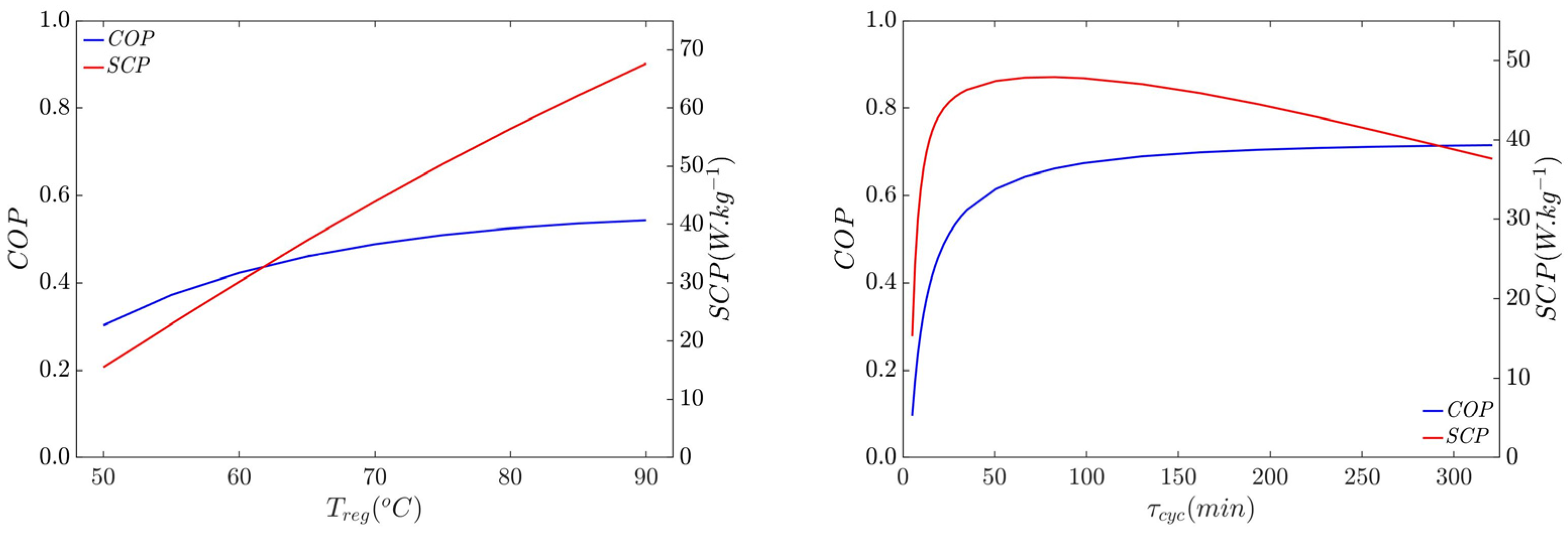
Figure 5 (left) depicts the influence of the regeneration temperature on the AC’s performance for a cycle time of 22.2 min and of the cycle time (right) for a regeneration temperature of 70 °C. It is noticeable that variations in the regeneration temperature affected the SCP more severely than the COP, given that higher regeneration temperatures led to faster heat exchange between the HTF and the adsorbent material. Identifying the optimal cycle time is one of the most important parameters in every adsorption system, its identification usually being complex due to the opposite behaviours of the COP and SCP. In this particular case, these opposite behaviours were present for cycle times higher than 83 min, where the COP kept increasing with the cycle time and the SCP started to decrease. As the cycle time increased, the SCP decreased, since the extra energy that was obtained by running longer (and more complete) cycles did not compensate for the increase in the cycle duration. The optimal balance between the COP and the SCP must be found for each individual adsorption system and, in this case, for each individual AC.
4. Conclusions
This work presents an AC driven by surplus heat from thermal solar collectors suitable for residential space cooling applications. This system can be used to provide cooling to residential buildings during the hot summer months solely using the inherent heat surplus that is generated by solar thermal collectors during warm seasons. The AC uses silica gel–water as the working pair and was modelled with a two-dimensional distributed parameter model. The model was used to simulate the thermally driven cooling system and calculate its performance coefficients. Considering the reference parameters, which corresponded to a hot summer day in the Aveiro region, the thermal cooling system had a COP of 0.5 and a total cooling power of approximately 235 W. A larger unit would be required to provide cooling to households, what can be accomplished either by increasing the adsorbent mass in the adsorber or by using several adsorbers in parallel. Analysis of the system main governing parameters of the thermally driven cooling was carried out. The results showed that, despite the lower performance for lower evaporator temperatures and higher condenser temperatures, the system could accommodate evaporator temperatures as low as 2 °C and condenser temperatures as high as 42 °C, demonstrating that it is still viable on hotter days. Using the heat surplus of solar thermal systems, the thermally driven cooling system could work close to its maximum COP and deliver more than half of its maximum SCP. Despite the low performance of the thermally driven cooling system, this technology is worthy of further research and development, considering that the energy required to drive the system is freely obtained (clean and cheaper). The same base adsorption system can be used for cooling purposes in summer or for heating purposes in winter.
Author Contributions
Conceptualization, methodology and analysis, J.M.S.D. and V.A.F.C.; writing—original draft preparation, J.M.S.D.; writing—review and editing, J.M.S.D. and V.A.F.C.; supervision, V.A.F.C. All authors have read and agreed to the published version of the manuscript.
Funding
This work was funded by the grant SFRH/BD/145124/2019 and the projects UIDB/00481/2020 and UIDP/00481/2020-FCT—Fundação para a Ciência e a Tecnologia and CEN-TRO-01-0145-FEDER-022083—Centro Portugal Regional Operational Programme (Centro2020), under the PORTUGAL 2020 Partnership Agreement through the European Regional Development Fund.
Acknowledgments
The present study was developed in the scope of the Smart Green Homes Project (PO-CI-01-0247-FEDER-007678), a co-promotion between Bosch Termotecnologia S.A. and the University of Aveiro. It was financed by Portugal 2020 under the Competitiveness and Internationalization Operational Program and by the European Regional Development Fund.
Conflicts of Interest
The authors declare no conflict of interest.
Nomenclature
| AC | Adsorption cooling |
| C | Specific heat (J·kg−1·K−1) |
| Cp | Constant pressure specific heat (J·kg−1·K−1) |
| COPc | Cooling coefficient of performance |
| d | Diameter (m) |
| Def0 | Effective diffusion coefficient (m2·s−1) |
| Ea | Activation energy (J·kg−1) |
| HTF | Heat transfer fluid |
| hf→m | Fluid–metal convective heat transfer coefficient (W·m−2·K−1) |
| hm→s | Adsorbent–metal heat transfer coefficient (W·m−2·K−1) |
| k | Thermal conductivity (W·m−1·K−1) |
| k0 | Pre-exponential coefficient (kg·kg−1·Pa−1) |
| kD | Blake–Kozeny permeability (m2) |
| KLDF | LDF constant (s−1) |
| L | Tube length (m) |
| m | Mass (kg) |
| P | Pressure (Pa) |
| Q | Heat (J) |
| qm | Monolayer specific capacity (kg·kg−1) |
| r | Radial coordinate (m) |
| Rp | Particle radius (m) |
| R′ | Adsorbate specific gas constant (J·kg−1·K−1) |
| SCP | Specific cooling power (W·kg−1) |
| t | Time (s) |
| tSG | Non-dimensional Toth constant |
| T | Temperature (K) |
| u | Adsorbate velocity (m·s−1) |
| v | Velocity (m·s−1) |
| X | Adsorbate concentration in the adsorbent (kga·kgs−1) |
| z | Axial longitudinal coordinate (m) |
| Subscripts | |
| a | Adsorbate |
| ads | Adsorption |
| bed | Adsorbent bed |
| c | Condenser/cooling |
| cyc | Cycle |
| e | Evaporator |
| eq | Equilibrium |
| f | Fluid |
| h | Heating |
| ic | Isosteric cooling |
| ih | Isosteric heating |
| in | Inner |
| ini | Initial |
| m | Metal |
| max | Maximum |
| min | Minimum |
| out | Outer |
| p | Particle |
| reg | Regeneration |
| s | Adsorbent |
| v | Vapour/vaporization |
| Greek letters | |
| ΔHads | Adsorption heat (J·kg−1) |
| ΔHv | Heat of vaporization (J·kg−1) |
| ε | Adsorbent bed porosity |
| μ | Dynamic viscosity (Pa·s) |
| ρ | Adsorbate density (kg·m−3) |
| σ | Thickness (m) |
| τ | Cycle time (s) |
References
- REN21. Renewables 2020 Global Status Report; REN21: Paris, France, 2020. [Google Scholar]
- Boruta, P.; Bujok, T.; Sztekler, M.K. Adsorbents, Working Pairs and Coated Beds for Natural Refrigerants in Adsorption Chillers—State of the Art. Energies 2021, 14, 4707. [Google Scholar] [CrossRef]
- Boman, D.B.; Hoysall, D.C.; Pahinkar, D.G.; Ponkala, M.J.; Garimella, S. Screening of working pairs for adsorption heat pumps based on thermodynamic and transport characteristics. Appl. Therm. Eng. 2017, 123, 422–434. [Google Scholar] [CrossRef]
- Freni, A.; Maggio, G.; Sapienza, A.; Frazzica, A.; Restuccia, G.; Vasta, S. Comparative analysis of promising adsorbent/adsorbate pairs for adsorptive heat pumping, air conditioning and refrigeration. Appl. Therm. Eng. 2016, 104, 85–95. [Google Scholar] [CrossRef]
- Calabrese, L.; Bonaccorsi, L.; Freni, A.; Proverbio, E. Silicone composite foams for adsorption heat pump applications. Sustain. Mater. Technol. 2017, 12, 27–34. [Google Scholar] [CrossRef]
- Calabrese, L.; Brancato, V.; Bonaccorsi, L.; Frazzica, A.; Caprì, A.; Freni, A.; Proverbio, E. Development and characterization of silane-zeolite adsorbent coatings for adsorption heat pump applications. Appl. Therm. Eng. 2017, 116, 364–371. [Google Scholar] [CrossRef]
- Henninger, S.K.; Ernst, S.-J.; Gordeeva, L.G.; Bendix, P.; Fröhlich, D.; Grekova, A.D.; Bonaccorsi, L.; Aristov, Y.; Jaenchen, J. New materials for adsorption heat transformation and storage. Renew. Energy 2017, 110, 59–68. [Google Scholar] [CrossRef]
- Kim, C.; Cho, K.; Kim, S.K.; Lee, E.K.; Kim, J.-N.; Choi, M. Alumina-coated ordered mesoporous silica as an efficient and stable water adsorbent for adsorption heat pump. Microporous Mesoporous Mater. 2017, 239, 310–315. [Google Scholar] [CrossRef]
- Pinheiro, J.M.; Valente, A.A.; Salústio, S.; Ferreira, N.; Rocha, J.; Silva, C.M. Application of the novel ETS-10/water pair in cyclic adsorption heating processes: Measurement of equilibrium and kinetics properties and simulation studies. Appl. Therm. Eng. 2015, 87, 412–423. [Google Scholar] [CrossRef]
- Zhang, L.Z.; Wang, L. Effects of coupled heat and mass transfers in adsorbent on the performance of a waste heat adsorption cooling unit. Appl. Therm. Eng. 1999, 19, 195–215. [Google Scholar] [CrossRef]
- Poyelle, F.; Guilleminot, J.-J.; Meunier, F. Experimental Tests and Predictive Model of an Adsorptive Air Conditioning Unit. Ind. Eng. Chem. Res. 1999, 38, 298–309. [Google Scholar] [CrossRef]
- Freni, A.; Frazzica, A.; Dawoud, B.; Chmielewski, S.; Calabrese, L.; Bonaccorsi, L. Adsorbent coatings for heat pumping applications: Verification of hydrothermal and mechanical stabilities. Appl. Therm. Eng. 2013, 50, 1658–1663. [Google Scholar] [CrossRef]
- Girnik, I.S.; Grekova, A.D.; Gordeeva, L.G.; Aristov, Y.I. Dynamic optimization of adsorptive chillers: Compact layer vs. bed of loose grains. Appl. Therm. Eng. 2017, 125, 823–829. [Google Scholar] [CrossRef]
- Kowsari, M.M.; Niazmand, H.; Tokarev, M. Bed configuration effects on the finned flat-tube adsorption heat exchanger performance: Numerical modeling and experimental validation. Appl. Energy 2018, 213, 540–554. [Google Scholar] [CrossRef]
- Rivero-Pacho, A.M.; Critoph, R.E.; Metcalf, S.J. Modelling and development of a generator for a domestic gas-fired carbon-ammonia adsorption heat pump. Renew. Energy 2017, 110, 180–185. [Google Scholar] [CrossRef] [Green Version]
- Wittstadt, U.; Füldner, G.; Laurenz, E.; Warlo, A.; Große, A.; Herrmann, R.; Schnabel, L.; Mittelbach, W. A novel adsorption module with fiber heat exchangers: Performance analysis based on driving temperature differences. Renew. Energy 2017, 110, 154–161. [Google Scholar] [CrossRef]
- Sapienza, A.; Gullì, G.; Calabrese, L.; Palomba, V.; Frazzica, A.; Brancato, V.; La Rosa, D.; Vasta, S.; Freni, A.; Bonaccorsi, L.; et al. An innovative adsorptive chiller prototype based on 3 hybrid coated/granular adsorbers. Appl. Energy 2016, 179, 929–938. [Google Scholar] [CrossRef]
- Palomba, V.; Vasta, S.; Freni, A. Experimental testing of AQSOA FAM Z02/water adsorption system for heat and cold storage. Appl. Therm. Eng. 2017, 124, 967–974. [Google Scholar] [CrossRef]
- Dawoud, B. On the development of an innovative gas-fired heating appliance based on a zeolite-water adsorption heat pump; system description and seasonal gas utilization efficiency. Appl. Therm. Eng. 2014, 72, 323–330. [Google Scholar] [CrossRef]
- Fernandes, M.S.; Brites, G.J.V.N.; Costa, J.J.; Gaspar, A.R.; Costa, V.A.F. Review and future trends of solar adsorption refrigeration systems. Renew. Sustain. Energy Rev. 2014, 39, 102–123. [Google Scholar] [CrossRef]
- Dias, J.M.S.; Costa, V.A.F. Which dimensional model for the analysis of a coated tube adsorber for adsorption heat pumps? Energy 2019, 174, 1110–1120. [Google Scholar] [CrossRef]
- Dias, J.M.S.; Costa, V.A.F. Modeling and Analysis of a Coated Tube Adsorber for Adsorption Heat Pumps. Energies 2021, 14, 6878. [Google Scholar] [CrossRef]
- Dias, J.M.S.; Costa, V.A.F. Evaluating the performance of a coated tube adsorber for adsorption cooling. [Évaluation de la per-formance d’un adsorbeur à tube enrobé pour le refroidissement par adsorption]. Int. J. Refrig. 2020, 118, 21–30. [Google Scholar] [CrossRef]
- Dias, J.M.S.; Costa, V.A.F. Adsorption heat pumps for heating applications: A review of current state, literature gaps and development challenges. Renew. Sustain. Energy Rev. 2018, 98, 317–327. [Google Scholar] [CrossRef]
- Li, X.H.; Hou, X.H.; Zhang, X.; Yuan, Z.X. A review on development of adsorption cooling—Novel beds and advanced cycles. Energy Convers. Manag. 2015, 94, 221–232. [Google Scholar] [CrossRef]
- Pesaran, A.; Lee, H.; Hwang, Y.; Radermacher, R.; Chun, H.-H. Review article: Numerical simulation of adsorption heat pumps. Energy 2016, 100, 310–320. [Google Scholar] [CrossRef]
- Wilkes, J.O.; Birmingham, S.G. Fluid Mechanics for Chemical Engineers with Microfluidics and CFD; Pearson Education: London, UK, 2006. [Google Scholar]
- Sircar, S. Linear-driving-force model for non-isothermal gas adsorption kinetics. J. Chem. Soc. Faraday Trans. 1 Phys. Chem. Condens. Phases 1983, 79, 785–796. [Google Scholar] [CrossRef]
- Shampine, L.F.; Reichelt, M.W. The MATLAB ODE Suite. SIAM J. Sci. Comput. 1997, 18, 1–22. [Google Scholar] [CrossRef] [Green Version]
- Muttakin, M.; Islam, M.A.; Malik, K.S.; Pahwa, D.; Saha, B.B. Study on optimized adsorption chiller employing various heat and mass recovery schemes. Int. J. Refrig. 2021, 126, 222–237. [Google Scholar] [CrossRef]
- Wang, D.; Zhang, J.; Tian, X.; Liu, D.; Sumathy, K. Progress in silica gel–water adsorption refrigeration technology. Renew. Sustain. Energy Rev. 2014, 30, 85–104. [Google Scholar] [CrossRef]
- Alahmer, A.; Ajib, S.; Wang, X. Comprehensive strategies for performance improvement of adsorption air conditioning systems: A review. Renew. Sustain. Energy Rev. 2019, 99, 138–158. [Google Scholar] [CrossRef]
Figure 1.
(a) Adsorber schematic; (b) adsorber with fifty tubes covered with silica gel.
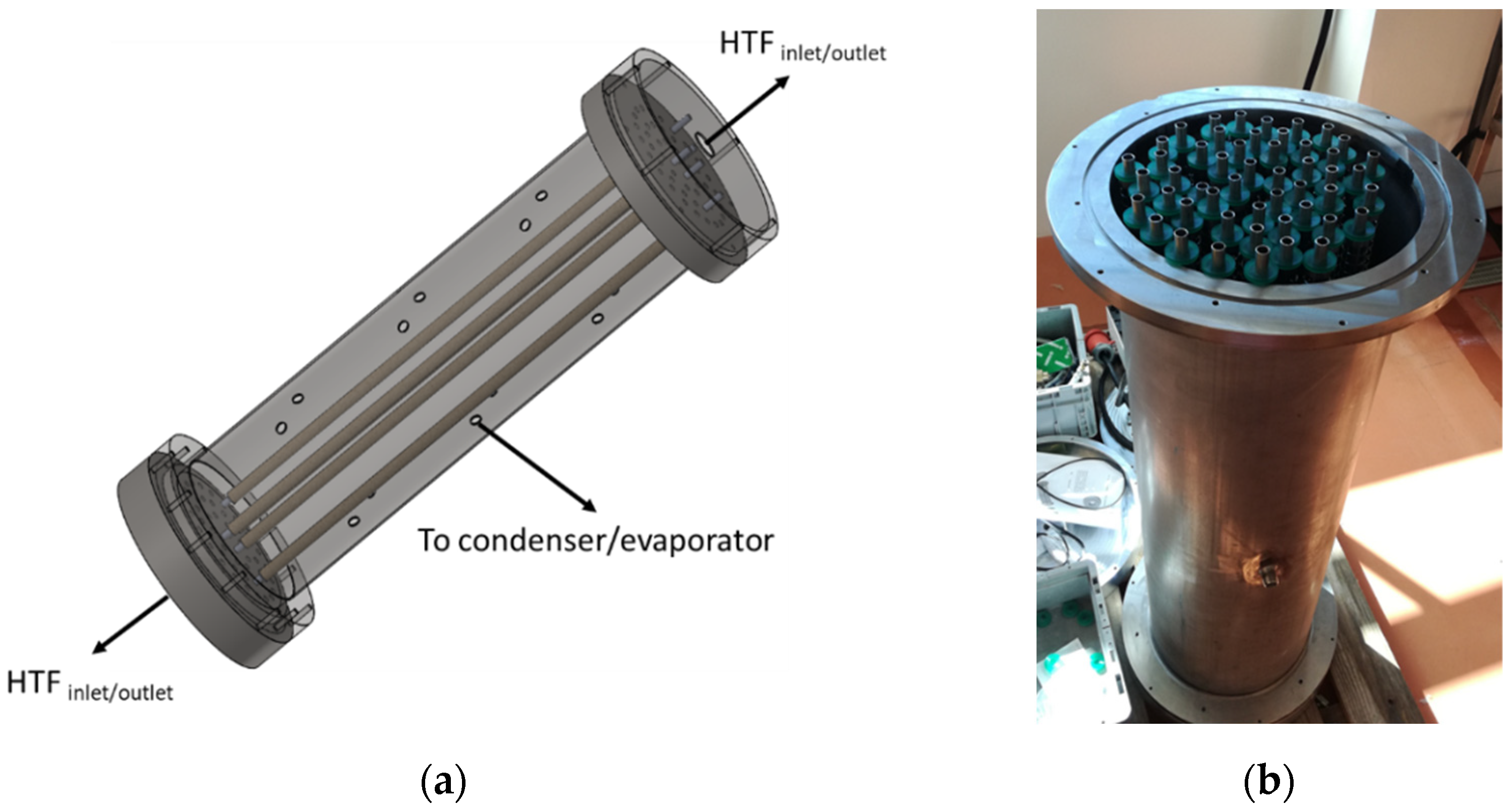
Figure 2.
Schematic of an AC driven by solar thermal heat used to remove heat from a residential building.
Figure 2.
Schematic of an AC driven by solar thermal heat used to remove heat from a residential building.
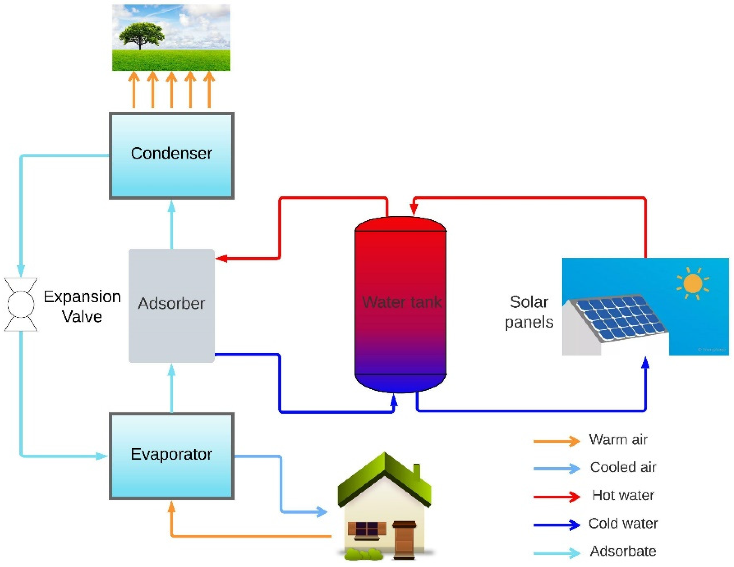
Figure 3.
Ideal thermodynamic cycle of the AC.
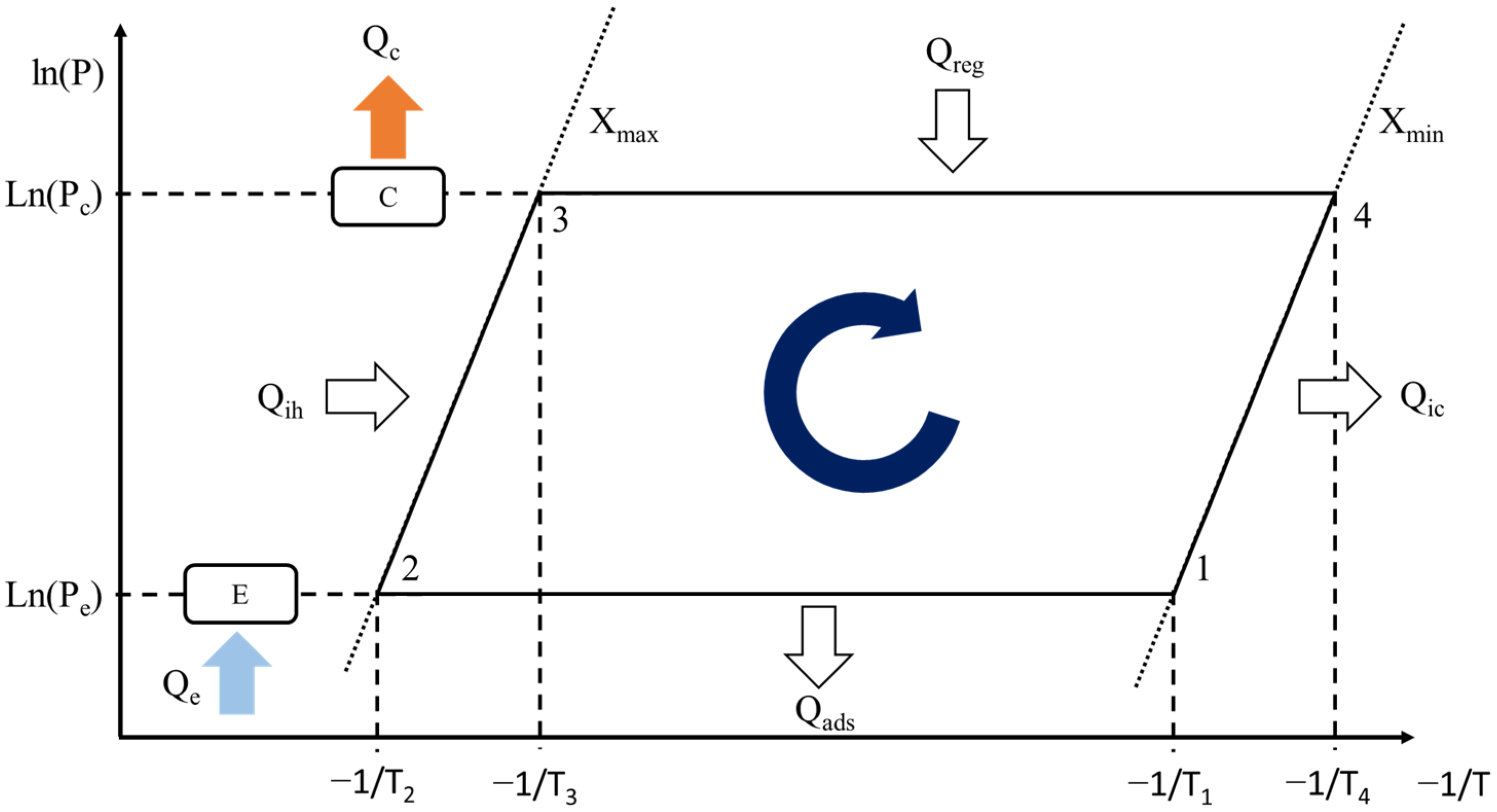
Figure 4.
COP and SCP variation with the evaporator (on the (left)) and condenser (on the (right)) temperatures.
Figure 4.
COP and SCP variation with the evaporator (on the (left)) and condenser (on the (right)) temperatures.

Figure 5.
COP and SCP variation with the regeneration temperature (on the (left)) and the cycle time (on the (right)).
Figure 5.
COP and SCP variation with the regeneration temperature (on the (left)) and the cycle time (on the (right)).

Table 1.
Reference parameters used to calculate the COP and SCP.
| Parameter | Value | Unit |
|---|---|---|
| Cs | 921 | J·kg−1·K−1 |
| din,tube | 0.01 | m |
| hm→s | 30 | W·m−2·K−1 |
| ks | 0.198 | W·m−1·K−1 |
| Ltube | 1 | m |
| ms | 5.35 | kg |
| tads | 600 | s |
| Tc | 30 | °C |
| Te | 15 | °C |
| Tf,ads | 18 | °C |
| Tf,reg | 70 | °C |
| vHTF | 0.05 | m·s−1 |
| ρs | 2027 | kg·m−3 |
| σs | 0.002 | m |
Publisher’s Note: MDPI stays neutral with regard to jurisdictional claims in published maps and institutional affiliations. |
© 2022 by the authors. Licensee MDPI, Basel, Switzerland. This article is an open access article distributed under the terms and conditions of the Creative Commons Attribution (CC BY) license (https://creativecommons.org/licenses/by/4.0/).
Share and Cite
MDPI and ACS Style
Dias, J.M.S.; Costa, V.A.F. Adsorption Cooler Design, Dynamic Modeling, and Performance Analyses. Clean Technol. 2022, 4, 1152-1161. https://doi.org/10.3390/cleantechnol4040070
AMA Style
Dias JMS, Costa VAF. Adsorption Cooler Design, Dynamic Modeling, and Performance Analyses. Clean Technologies. 2022; 4(4):1152-1161. https://doi.org/10.3390/cleantechnol4040070
Chicago/Turabian StyleDias, João M. S., and Vítor A. F. Costa. 2022. "Adsorption Cooler Design, Dynamic Modeling, and Performance Analyses" Clean Technologies 4, no. 4: 1152-1161. https://doi.org/10.3390/cleantechnol4040070