
Concrete Alkali–Aggregate-Reactivity-Induced Steel Reinforcement Corrosion


Centre for Infrastructure Performance and Reliability, The University of Newcastle, Callaghan 2308, Australia
*
Author to whom correspondence should be addressed.
Corros. Mater. Degrad. 2023, 4(3), 428-444; https://doi.org/10.3390/cmd4030022
Submission received: 24 May 2023
/
Revised: 17 July 2023
/
Accepted: 18 July 2023
/
Published: 21 July 2023
Abstract
:The alkali–aggregate reactivity (AAR) of concrete, long known for mass concrete, can also induce corrosion of steel in reinforced concrete structures. Several examples are given for which the origin of observed reinforcement corrosion and loss of concrete cover originally was attributed to chloride-induced or to carbonation-induced reinforcement corrosion. Critical reviews of these cases, using available information, suggest that, more likely, the observed crack patterns and concrete deterioration are the result of long-term AAR-induced concrete matrix expansion and loss of concrete strength and that these effects occurred prior to the eventual initiation of reinforcement corrosion. This proposition is supported by finite element and other stress analyses of various concrete–steel ensembles. They show that concrete expansion produces tensile stresses localised at and near exterior concrete surfaces or relative to the reinforcement. The locations of high-stress and -strain zones so produced correlate with field observations of long-term concrete cracking and delamination. The present interpretations highlight that AAR may be a significant contributor to initiation and subsequent long-term development of reinforcement corrosion in structurally reinforced concretes.
1. Introduction
Corrosion of steel reinforcement in concrete structures most commonly is attributed to two causes: “chloride-induced” reinforcement corrosion, most commonly found in marine exposure environments, or “carbonation-induced” reinforcement corrosion, which is attributed to the carbonation of the concrete by the inwards diffusion of atmospheric carbon dioxide. In both cases, corrosion of the reinforcement leads to a gradual build-up of corrosion products around the reinforcement steel and within the immediately adjacent concrete matrix. Together, these are responsible for cracking, spalling, and delamination of the concrete cover, which is often observed for RC structures after many years of exposure [1].
The initiation and development of reinforcement corrosion, particularly in chloride-rich environments, has been the subject of much research [2]. However, it is clear that the initiation of corrosion, including that of steel, requires satisfaction of the thermodynamic conditions for the underlying (electro-)chemical reactions [3]. For steel encased in concrete, this implies sufficient reduction of the concrete pH at the concrete–steel interface. In the case of chloride-rich environments, the critical pH depends also on the chloride concentration at the surface of the steel reinforcement, with pitting feasible at a higher pH than required for general corrosion [3,4]. The general corrosion often seen in longer-term exposures requires the pH of the concrete pore solution in contact with the steel reinforcement to be reduced further. Typically, this is the result of the loss of OH− ions due to the slow, long-term dissolution and outward diffusion of concrete hydroxides, with the latter being, in the long-term, principally calcium hydroxide (Ca(OH)2) [5]. The importance of this loss relative to reinforcement corrosion has been demonstrated experimentally [6], including for chloride-related reinforcement corrosion. The thickness and quality of the concrete cover play important roles. The concrete cover provides a barrier to inward diffusion of chlorides, oxygen, and carbon dioxide [1]. It also may delay the outward loss of hydroxides and thus the lowering of the pH of the concrete matrix. It follows that poor-quality cover likely will facilitate the early initiation and faster development of reinforcement corrosion. This possibility most commonly is associated with weak or permeable concretes, possibly resulting from poor compaction or poor mix proportions [7,8]. However, there is another possibility that has been largely ignored within the structural concrete community until relatively recently [9,10]. That possibility is the gradual deterioration of concrete cover through the action of alkali–aggregate reactions (AAR). Such deterioration of the concrete will lower its strength and its resistance to permeability, thereby potentially impairing its protective nature and its role as a diffusion barrier.
The next section provides a brief description of several cases of reinforcement corrosion and concrete structural damage that originally were attributed to either chloride-induced reinforcement corrosion or to carbonation-induced reinforcement corrosion. A closer examination of these cases, however, suggests that they are more likely to have arisen from what might be termed AAR-induced reinforcement corrosion. This re-assessment arises from considering the local environment and the likely source and type of the aggregates used in the concrete. Further, the observations of concrete expansion and cracking (and in some cases other forms of deterioration) indicates that these could be interpreted as the result of moderate AAR of the concrete aggregates preceding subsequent reinforcement corrosion. This is the reverse of chloride-induced and carbonation-induced reinforcement corrosion. The available evidence to date indicates that it is only the loss of concrete protection caused by AAR that then leads to reinforcement corrosion. As should be evident [1] and as shown experimentally [6], this can lead to loss of alkali material at the steel bar surfaces (i.e., loss of chemical protection) and loss of physical protection usually afforded by the presence of concrete around reinforcement bars.
To support the above interpretations, the Discussion section provides stress analyses for several typical cases. These show the local stress states likely caused by the expansive effect on the concrete matrix of alkaline aggregate reactivity. The resulting stress states allow inferences of the likely crack patterns that would be observed in practice for comparison with actual observations. It is concluded that the structural damage effects of severe AAR are relatively easily identified once it is realized that AAR might be involved. Further, it is concluded that relatively moderate concrete expansion resulting from AAR of the aggregates can cause concrete deterioration, including cracking. In turn, this can lead to subsequent reinforcement corrosion. Such cases are not always easily distinguished from the inverse process of reinforcement corrosion caused or initiated by chloride-induced or carbonation-induced reinforcement corrosion with subsequent concrete cracking. The largely anecdotal observations herein point to matters of practical importance, but they also give rise to a need for further research. It is noted that the mechanics and chemistry of the alkali–aggregate reactions themselves are well known and documented and need not be considered herein. Also, procedures for testing aggregates for AAR potential are not considered herein. Both aspects have had detailed treatment in the existing literature [9,11,12]. Rather, the focus of the present paper is on the research gap regarding the damaging effects of AAR on the concrete that have not usually been differentiated from those of chloride-induced and carbonation induced reinforcement corrosion and subsequent damage to structural concrete.
2. Background
The potentially severe deleterious effect of alkali–aggregate reactivity (AAR) for concretes has been known since at least the 1940s [13] but recognized mainly as a factor for massive concrete structures such as dams and road pavements. Even then, for many years, British and other investigators considered AAR a problem only for “other parts of the world” [14], and cases for which AAR was implicated were considered “exceptions” rather than examples of a more general problem [12].
AAR occurs mostly as alkali–silicate reactions (ASR) in which the concrete alkalis attack the silicate content of aggregates. Alkali–carbonate reactivity (ACR) is less common. In both cases, in the presence of moisture, the products of the AAR on aggregates cause the concrete to expand, thereby reducing concrete strength and increasing its permeability. The reactions themselves have been the subject of much investigation and appear well understood [9,14,15]. They may occur relatively quickly (one or two decades) but in other cases may occur over many decades [9,12]. Typically, as a result of the alkali–aggregate reaction of the aggregates, the concrete develops widespread, apparently random cracking or crazing of their external surfaces. In some climatic regions, such damage may be difficult to distinguish from other forms of concrete surface damage, including frost or freeze–thaw cycling, surface exsiccation due to inadequate curing, or poor workmanship [7], ([16] p. 281).
Random cracking and crazing of concrete surfaces have been observed also for reinforced concrete structures, in some cases with some preference for the orientation of the reinforcement steel. Where structures were examined in detail, exposed reinforcement usually was still well embedded in the concrete, with little evidence of corrosion other than where the cover was lost ([16], pp. 50–51). In other cases, cracking of the concrete was observed to be aligned preferentially with the main reinforcement bars, specifically those closest to the concrete surface [10]. This was considered as possibly the result of the slightly lower net presence of concrete along those lines. Alignment of concrete cracking with reinforcement bars also occurs for chloride-induced and carbonation-induced reinforcement corrosion. It follows that, in general, conclusions cannot be drawn about the underlying cause(s) of surface cracking from visual observations alone ([9], p. 281). More specifically, the presence of corroded bars does not provide proof that the gradual build-up of rusts caused cracking adjacent to the reinforcement bars. Instead, the available evidence suggests that for concretes subject to relatively moderate AAR and thus moderate concrete expansion and loss of concrete tensile strength, the observed concrete cracking and/or loss of cover could have preceded the initiation and development of reinforcement corrosion. This would then have allowed some degree of reinforcement corrosion to occur, thereby permitting some rust deposition on the adjacent exposed concrete matrix. The timing involved also is not conclusive. Except in the most severe cases of AAR attack, in practice, the time taken for AAR to become evident through the destruction of the concrete cover is not dissimilar to the times necessary for chloride-induced or carbonation-induced corrosion damage to become evident [12,14].
As noted, similar to chloride-induced or carbonation-induced corrosion, for AAR to be active requires the availability of moisture. As a result, AAR often is more severe in areas such as run-offs or where exposure to seawater or to condensation may occur [10]. These also are the locations and conditions recognized as associated with increased corrosion of reinforcement under chloride-induced or carbonation conditions. Overall, this indicates that a greater degree of discrimination is required to separate reinforcement corrosion originating from concrete deterioration caused by AAR from reinforcement corrosion initiated by chloride or carbonation mechanisms and conditions.
3. Field observations
3.1. Reinforcement Corrosion Attributed to Chloride Exposure
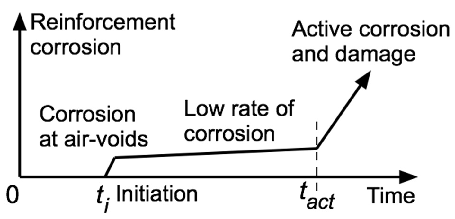
An analysis of some 300 cases of reinforced concrete structures presumed to have been influenced by chlorides from marine exposures or from de-icing salts on highway bridges, the latter mainly in the USA, has been reported earlier [17]. This showed that the time to reinforcement corrosion initiation (ti) and the estimated time to the commencement of active corrosion (tact), that is, to the commencement of structural damage to the concrete (Figure 1), in both cases was not strongly dependent on the estimated higher concentration of chlorides in the concretes (Figure 2). This was for concretes made with siliceous aggregates and for concrete made with calcareous aggregates, although the latter concrete appeared to have comparatively greater ti and tact. Subsequent to that analysis, it became evident that many of the Norwegian aggregates used in reinforced concrete construction were subject to AAR [18], ([16], pp. 75–84). When the values for ti and tact for those cases likely affected by AAR were taken out of the database and the trends replotted, it became clear that both ti and tact increased in value for a given concentration of chlorides at the reinforcing bars and that the corresponding scatter in the datasets was less (Figure 2). At that time and still today, it is considered unlikely that further progress can be made with this database owing to the unavailability of information about the type of aggregates and hence the possibility of AAR being involved.
3.2. WW2 Reinforced Concrete Handrails at Arbroath, Scotland (UK)
The condition of the reinforced concrete handrails along King’s Drive, northeast of Arbroath, Scotland, and directly facing the North Sea, has been described in some detail before [21,22]. The earlier reports placed emphasis on some 900 essentially identical but individually pre-cast elements each, about 2 m long and some 150 mm deep × 130 mm wide in cross-section, made during 1943. These elements were found to contain seashells and to have aggregate of widely varying sizes, with wide variations in the 25 mm nominal concrete cover to the 6 mm diameter reinforcing bars. With just a few exceptions, even after some 65 years of continuous exposure to the North Sea marine atmosphere, the reinforcement bars showed almost no evidence of corrosion when extracted from the concretes. Little attention was given in those papers to the condition of some 100 elements located apparently randomly in the overall balustrade and deduced as having been made in 1968 (and some in 1993), presumably as replacements for failed 1943 elements. At the same time as the 1943 elements were examined in detail [21], it was observed that the 1968 elements, which had only two 12 mm diameter (nominal) reinforcement bars and 30 mm nominal cover, showed very considerable damage. They showed wide longitudinal cracking in various radial and other directions but with only a limited amount of rust products around the reinforcing bars (Figure 3). This suggests that the build-up of rust products as corrosion progressed was unlikely to be directly responsible for the damage to the concrete.
As reported earlier [21,22], compared to the 1943 concretes, the 1968 concretes showed no seashells in the concrete, suggesting the use of seawater in the mix was unlikely. Also, by that time, seawater for concrete mixes would have been prohibited. Relative to the 1943 concrete, the aggregates in the 1968 concrete appeared to be harder and the concrete overall denser and more compact. This suggests greater attention to mix design and construction, including sourcing of aggregates. In this context, it is of interest that a major bridge at Montrose, only some 18 km from Arbroath, built in 1930 presumably with what was at the time considered the best available materials, showed by the early 1990s considerable cracking, which was eventually attributed to AAR [23]. Although now impossible to confirm, this suggests that the extensive cracking (Figure 3) of the 1968 concrete is likely the result of AAR as distinct from chloride-induced reinforcement corrosion.
3.3. Concrete Structures on and near the Yucatan (MX) Coast
The very extensive southeast part of Mexico consists mainly of the Yucatan peninsula, with extensive limestone deposits as the predominant source for concrete aggregates and fine-crushed rock for construction, much of it quarried close to the northern Yucatan coast [24]. The resulting concrete typically was noted as porous and considered of relatively poor quality [25]. Building construction typically included off-form reinforced concrete walls, reinforced in-plane both vertically and horizontally. After some years of exposure to the atmosphere, these showed fine cracking and crazing and also quite extensive areas of concrete cover delamination [26]. These damages were attributed to poor “construction practices” and the use of high water–cement ratios, even though the latter would have been necessary to offset the porous nature of the limestone. Despite the overall damage and a high rate of loss of concrete alkalinity, which is attributed to carbonation [24], the photographs in the reports show only low to moderate reinforcement corrosion and limited penetration of corrosion products into the surrounding concrete.
In the same region, the relatively short life of the so-called “second” Progreso pier has striking similarities. It was built essentially with the same materials as the domestic constructions and was demolished after about 30 years owing to extensive damage attributed to marine corrosion of the reinforcement in its flat slab deck and above the mean tide level for the supporting piers. This case has been used repeatedly to argue the poor performance in chloride-rich marine environments of reinforced concrete structures with conventional steel reinforcement [27]. However, in view of much more recent evidence of the long-term durability of well-made reinforced concrete structures in marine environments [2,28], this simple interpretation is unlikely to be correct.
The Yucatan reinforced concretes were all made, as noted, with local limestone as aggregate. As seen in Figure 1, provided the aggregates are not reactive, the use of limestone should have had the beneficial effect of extending the times to initiation (ti) and the time to active corrosion (tact) (Figure 2). But as noted, this does not appear to be the case both for on-land reinforced concrete structures and for the second Progreso pier. The likely reason lies with the character of the Yucatan limestones.
The northern part of the Yucatan Peninsula (and many other surrounding areas) was subject to widespread fall-out of silica materials from a meteorite estimated to have impacted the Peninsula some 65 ± 0.2 Ma ago (the so-called Chicxulub impact event) at a location only a few kilometres from the modern-day town of Progreso. The siliceous “impact ejecta” layer is buried to various depths [29], and mixed in with the quarried limestone rock, this would facilitate alkali–silica reactivity (ASR). In turn, this likely is responsible for the observed damage of the concrete surfaces in buildings [26]. It also is likely to be responsible for the early deterioration of the piers and slab of the second Progreso pier. In contrast, the original Progreso pier, built during the late 1930s, is largely a massive concrete structure using local limestone for aggregate but with very little reinforcement, which is mainly buried deep inside the concrete and for which any ASR would have little or no significance for reinforcement corrosion. However, an inspection in 2001 showed the exterior concrete surfaces to have widespread fine cracking, some up to 3 mm in size [30]. This is not inconsistent with cracking typical for AAR (although other causes cannot be excluded).
3.4. Heritage Harbour-Side Crane Gantry, Amsterdam (NL)
The “Kraanspoor” (crane way) is a heritage reinforced concrete high-portal-frame gantry-type structure that is 270 m long, 8.7 m wide and 13.5 m and was built in 1950 in the Amsterdam harbour complex to support a rail-based crane system [31]. After the cessation of ship building in the 1960s, it fell into disrepair but was saved from demolition in 1997. Subsequently, it was surmounted by a modern three-story-high office complex (Figure 4a). Field inspection of the off-form reinforced concrete substructure during 2019 revealed very little evidence of reinforcement corrosion despite nearly 70 years of exposure to the marine atmosphere of the Amsterdam harbour. However, in some isolated locations, there was evidence of loss of concrete cover in the corners of concrete piers in purely atmospheric-exposure locations (Figure 4b,c). The flat surfaces of the columns also showed some loss of concrete aligned entirely with the locations of the steel bars underneath, as exemplified in Figure 4d. None of these can be considered closely consistent with carbonation-induced corrosion, noting that chloride-induced corrosion would be very unlikely for this site, which is located some 21 km from the North Sea but close to the freshwater (now) inland lake Ijsselmeer.
Prior to about 1990, the concrete industry in the Netherlands did not consider AAR as a threat to concrete structures [32], even though there was evidence of ASR for concretes dating back to the 1950s [33], which was attributed to the use at that time of land-based cherts (which are siliceous aggregates) and reactive sandstones. There also were several road bridges affected by ASR ([16], p. 18). Subsequently, an expanding concrete industry was forced to rely increasingly on aggregates sourced from the Ardennes in Belgium ([16], p. 26) and the North Sea and also on marine gravels such as porous chert, chalcedony, and impure sandstone sourced from the Meuse and the Rhine rivers. These aggregates all are known to be prone to AAR. It follows that almost certainly these were the aggregates used in the structural concrete of the Kraanspoor gantry and that potentially they and ASR are responsible for the observations in Figure 4.
3.5. Reinforced Concrete Bridge Piers (AU, NZ)
Early field observations of concrete cracking and surface deterioration for several east coast Australian reinforced concrete bridges and bridge piles exposed to tidal seawater attributed the damage to chloride-induced corrosion of the reinforcement [34]. Carbonation depths of less than 14 mm after 20–30 years of exposure showed that carbonation could be discounted as a factor, but detailed examination eventually showed that AAR was likely, noting that the coarse aggregates were mostly highly deformed quartz gravel of gneissic or schistic origin [35]. In terms of structural damage, the reinforced concrete piles of the bridges showed vertical cracking particularly near the edges of rectangular piles and, in the case of circular piles, isolated randomly spaced vertical cracking of various crack widths [36]. There also was evidence of concrete cover delamination, crumbling of exterior cover concrete, and “drumminess” of the concrete cover. Moreover, the cover concrete was easily removed to reveal corroded reinforcement.
Australian aggregates subject to AAR appear to react relatively slowly compared with Scandinavian aggregates and appear to be more subject to delayed ettringite formation and related expansion [35]. On the other hand, New Zealand South Island aggregates have been noted to be highly reactive [37], and some reinforced concrete piles for bridges have exhibited so-called “hour-glass” thinning of their profiles in the tidal region [38].
3.6. Reinforced Concrete Bridge Piers, Georgia (U.S.)
The influence of AAR on concrete construction has been noted also in the U.S. [7] but, as in other jurisdictions, appears to have been underestimated. For example, the deterioration by longitudinal cracking, spalling, and exposed reinforcement and softening of the concrete near the waterline observed for a reinforced concrete road bridge some 36 years old was attributed primarily to chloride-induced corrosion [39] because of elevated concentrations of concrete chlorides despite the bridge being located some 16 km inland from the Georgia Atlantic coast. The softening of the concrete, particularly below the water line, was considered possibly the result of some type of chemical or biological attack [39].
The bridge in question was one of several considered in a wider investigation of eleven reinforced and prestressed concrete highway bridges on and near the Atlantic coast in Georgia, USA, reported in Appendix A of a thesis by Holland [40]. The thesis itself deals mainly with the effects of various additives to produce high-performing concretes against sulphate attack and carbonation. Given the observations in the thesis of concrete softening, it is of interest whether the set of observations could be interpreted as examples of AAR rather than primarily of chloride-induced or carbonation-induced corrosion damage. All the bridges are located along or near the Atlantic coast and include crossings over seawater (mouths of rivers) over brackish waters and others over freshwaters. Table 1 summarises the information available for these bridges. With one exception (case 8), concrete chloride concentration measurements were not available. The use of limestone aggregates for some bridges was identified from field observations.
As shown in Table 1, some degree of longitudinal concrete cracking was observed for the reinforced concrete piles in eight bridges, in each case at or near the corners of the piles or, in one case, of the vertical guide-rail supports. Such cracking also can be observed, under enlargement and very detailed examination of photographs of the other bridges, for at least some piers. Only the piers of older bridges showed signs of rust staining, in some cases only when samples of the piers were broken open (site 8). Such staining is indicative of reinforcement corrosion, but it does not demonstrate that corrosion preceded concrete damage as usually assumed—it merely shows that reinforced corrosion occurred. It could equally have occurred after the concrete (cover) was damaged, such as could occur under AAR conditions. As now recognised, concrete cover cracking is consistent with the time- and moisture-dependent volumetric expansion of concrete under AAR conditions of whatever type [10,41].
The evidence of “hour-glass” profiles of some the concrete piers, concrete cover loss in and near the pier corners and typically in the tidal or waterline zones, and loss of concrete cement matrix material between aggregates, termed “surface abrasion” ([40], Figure A6), were proposed as possibly the result of sulphate attack. However, the field observations of sulphate concentration vary quite considerably between the bridge locations and do not appear closely correlated, even qualitatively, with “surface abrasion”. An alternative explanation lies with the AAR of the concrete aggregates since, as noted, AAR is known to weaken the concrete matrix, with an associated loss of concrete fines [10,41]. Typically, the effects of AAR increase with increased period of exposure, and this appears to be borne out in Table 1, with “abrasion” being more pronounced for the older concretes. Further support for the influence of AAR is that for case 8, the concrete cover of the extracted piles was noted as “soft” and easily “chiselled off” ([40], p. 64). Such softening usually is associated with loss of concrete integrity from AAR [41].
Finally, the U.S. Geological Survey information [28] indicates that for the state of Georgia, by far the dominant aggregate type is crushed granite, with only some 15% listed as crushed limestone. Many granites are known to be prone to AAR [9]. It follows that the observations in Table 1, proposed as primarily (but not only) the result of chloride-induced corrosion, are more likely the result of AAR activity. This is consistent with the observations of the deterioration of the concrete surface by the softening and of the localised longitudinal cracking in the direction of the reinforcement. The mechanisms by which such localised rather than uniform widespread cracking can occur are considered in the next section.
4. Analysis
The apparently random cracking or crazing typically observed for concrete surfaces for mass concrete affected by AAR has been associated with the time- and moisture-dependent volumetric expansion of concrete under AAR conditions of whatever type [41]. Such expansion will be slightly greater well within the concrete matrix, aided by the slight temperature rise associated with the alkali–aggregate reaction. For mass concrete objects, completely unrestrained, the result is likely to be simple volumetric expansion without significant induced stresses (or strains), although some in-plane tensile stresses may develop on the exterior surfaces. In theory, these would be spread evenly over larger uniform areas [15].
The situation for practical reinforced concrete structures, however, is rather different. These contain reinforcement, including longitudinal bars, stirrups, and hoops that tend to inhibit volumetric expansion. For longitudinal elements such as beams and piers, such restraint is principally for the concrete confined by the hoops and stirrups. The concrete not confined by these, such as cover concrete, is less constrained and has greater freedom to expand. This likely is one reason for the observations that where reinforcement is present close to the concrete surface, cracking of the surface concrete occurs, trending along the lines of the reinforcement [10]. Also, the presence of steel bars reduces the concrete that can act in tension, thereby tending to focus concrete cracking along the orientation of the reinforcement bars. Evidently, the extent to which this can occur and the width of resulting cracks will depend on the thickness of the concrete cover and on its spatial variability. In practical concrete structures, concrete cover is seldom uniform in thickness and properties [8].
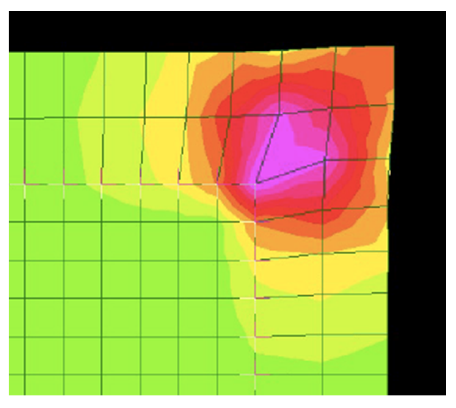
As to why cracking of piers and other longitudinal objects affected by AAR tends to occur at and near the corners (Figure 5), it is necessary to consider differential movement between the interior of the concrete piers and that at the surface and also the effects of the reinforcement and the presence of stirrups in relation to the expanding concrete under the volumetric expansion action of AAR. The main reinforcement and the stirrups act in combination as a “cage” to offer restraint to the interior concrete. The concrete cover, on the other hand, is not restrained directly by this cage, although there could be transfer of (mainly shear) resistance between the interior and exterior concrete. Evidently, the cover concrete is able to expand laterally (as well as transversely) at a different rate to the constrained bulk concrete. To ascertain the effects of these different strain conditions, the structural response was modelled using a standard finite element analysis program. For convenience and simplicity, the expansion was modelled using an increase in temperature of the concrete (but not the reinforcement steel) to create the material expansion and the resulting stress distribution. Without considering the precise details, the overall result of the analysis, in terms of the triaxial stresses generated by the volume expansion of the concrete, are shown in Figure 6. This is for a typical pier in Table 1, with a 450 × 450 mm cross-section with 60 mm cover. It is evident that the high triaxial stresses correspond to the corner zones where the tensile cracks are observed for AAR-affected concrete.
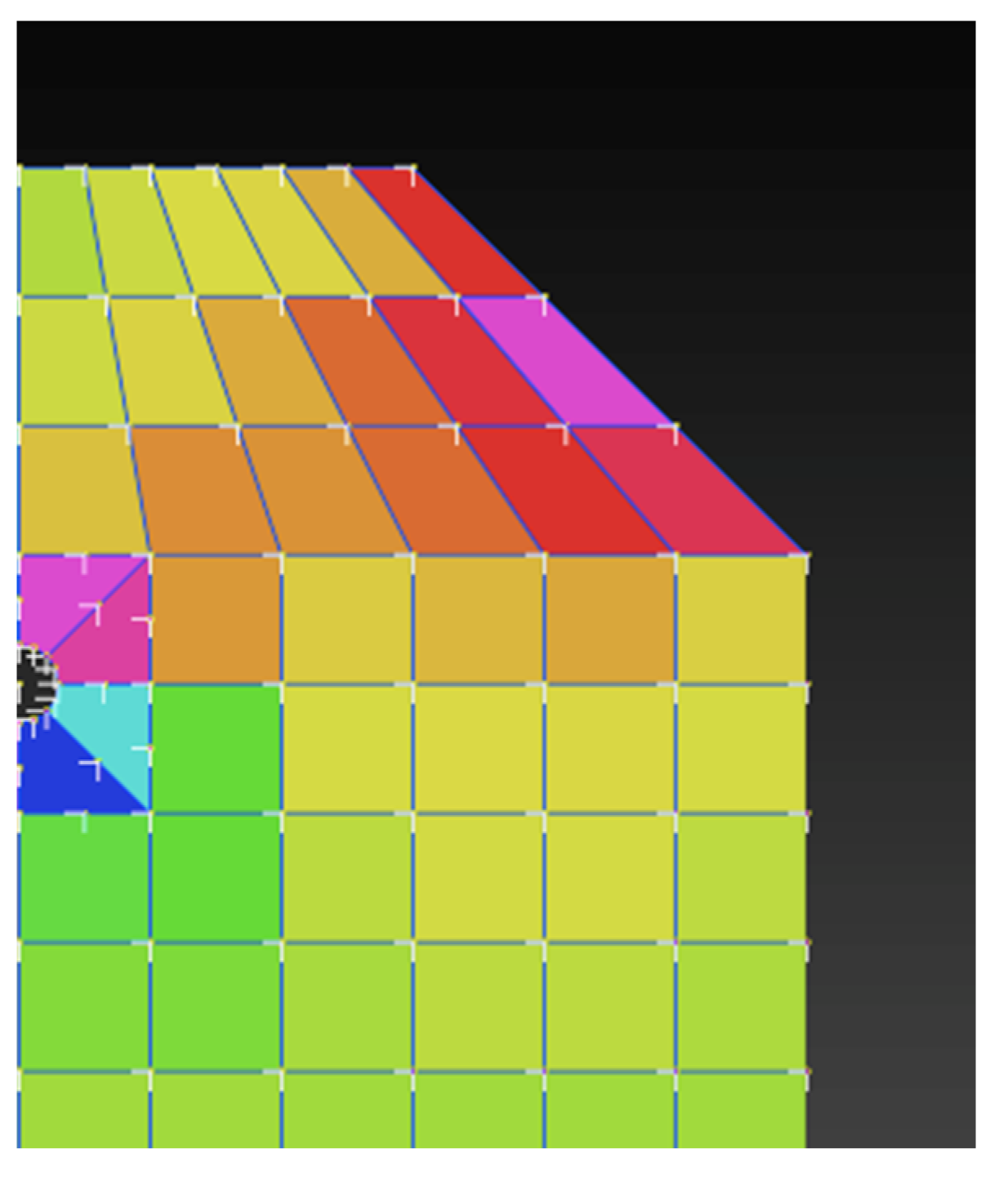
A generally similar result is obtained if the cross-section is changed to that corresponding to the handrails at Arbroath. Figure 7 shows the results for the triaxial stresses generated under volumetric expansion of the concrete. In this case, there is no hoop reinforcement. Nevertheless, the regions of high triaxial stress correspond with the pattern of cracking where it reaches the surface of the handrail (cf. Figure 5).
For circular columns, the stress analysis for volumetric expansion is elementary. It corresponds directly to that of a thin-walled pipe under internal pressure that generates a hoop (i.e., circumferential) tensile stress that, under idealised conditions, would be uniform around the circumference. In turn, for sufficient high tensile stress, this would result in fine uniform cracking all around the circumference. In practice, however, the concrete cover is unlikely to be precisely uniform around the circumference or of precisely the same tensile capacity. Thus, localisation of tensile stress and hence cracking is inevitable (Figure 8). Once commenced, such localized cracking is almost certain to extend longitudinally, causing isolated longitudinal cracking, as observed for practical circular piers, for example, those of the St. David highway bridge, Québec City, Canada [42].
Finally, the delamination of the concrete cover in the case of the two-way reinforced concrete walls and similar elements for Yucatan housing can be seen to follow a similar analysis, again based on concrete expansion. In this case, while the concrete will tend to expand in all directions under the influence of AAR, the steel reinforcement in contact with the concrete will tend to offer a degree of in-plane restraint to the expansion of the concrete in the direction of the reinforcement (Figure 9). If the concrete expansion is sufficient, the concrete shear capacity will be exceeded, and delamination will result. Obviously, this is an entirely different mode of delamination failure compared to that resulting from the build-up of rusts forcing the concrete laterally away from the reinforcement. The shearing pattern of failure along the plane of the reinforcement without significant build-up of rusts being required is consistent with the field observations of low to modest reinforcement corrosion [26].
5. Discussion
The examples given above all illustrate that crack patterns that might be associated with reinforcement corrosion initiated by chloride-induced or carbonation-induced initiation mechanisms are not dissimilar from cracking that can arise from the AAR of the concrete aggregates. This implies that misdiagnosis is possible—a possibility not helped by a perception in some parts of the concrete industry that AAR is a problem only associated with reinforced concrete structures “elsewhere” [9]. However, such a perception is not supported by the examples given above. They are drawn from a wide variety of locations nonetheless limited to those reported in the literature (Norwegian coastal structures and Australian and NZ bridge piers), those for which it has been possible to make reasonable deductions (e.g., Yucatan structures and Georgia bridge piers), or those available through personal inspection (Arbroath and Kraanspoor).
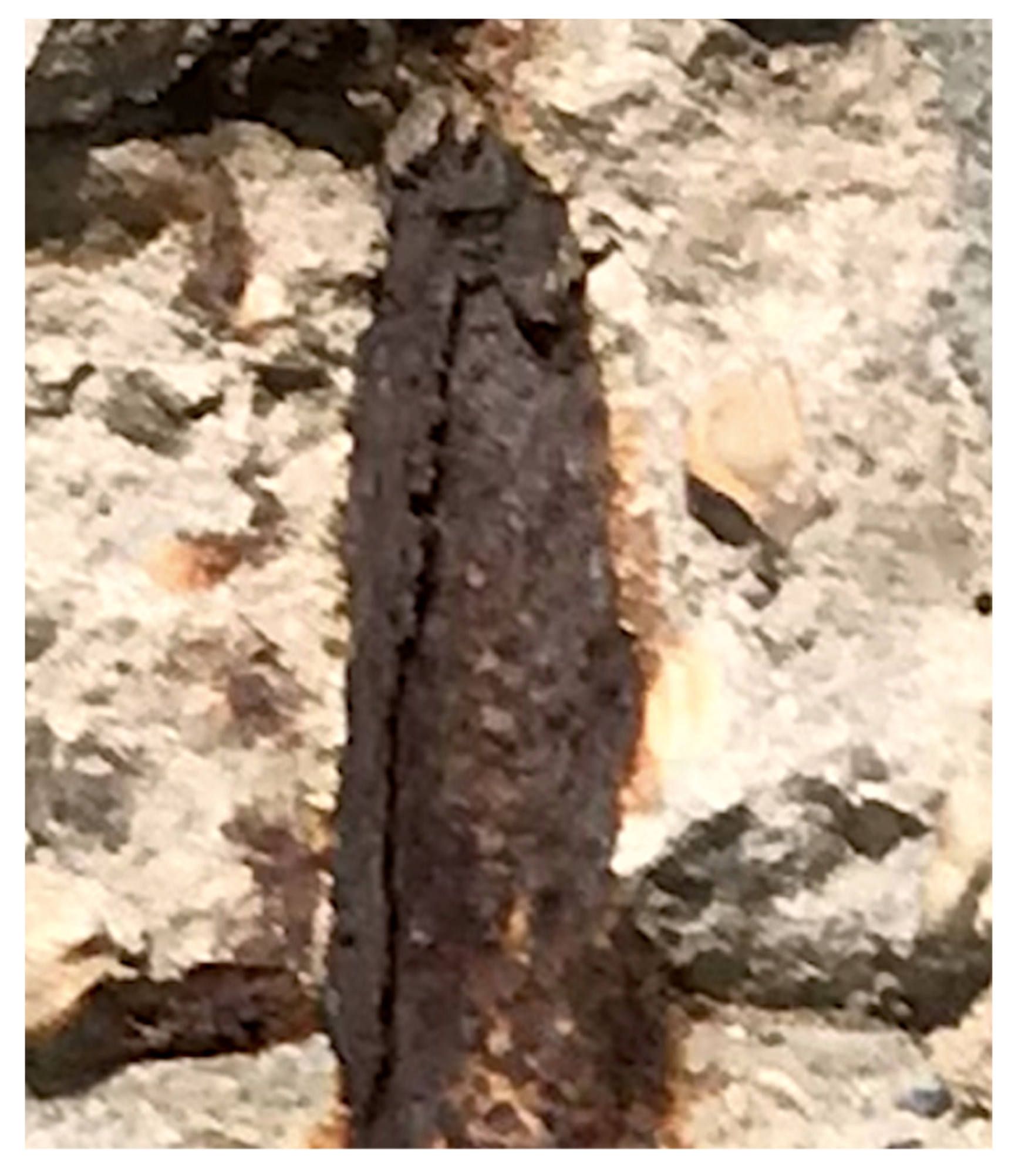
As has now been well established, the main structural concern with the AAR of aggregates is that its expansive effect tends to reduce the strength of the concrete and increase its permeability. The latter facilitates material deterioration as a function of time and exposure through the softening of the concrete and increasing its permeability, increasing the rate of loss of calcium hydroxide after it has undergone dissolution in water. Previous studies have shown that alkaline dissolution contributes to a more open, more permeable concrete matrix structure [6]. Likely, this is responsible for the relatively open structure of surface concrete (Figure 4b,c) affected by AAR and may be responsible for the apparently greater openness of the concrete matrix structure over the locations of the reinforcement bars (Figure 4d). This possibility is also supported by observations that where the concrete cover was lost, little evidence could be seen of reinforcement corrosion products (Figure 10). There also is little evidence of corrosion products having settled into the adjacent concrete matrix, as often reported [43]. There is also little evidence of rust staining, as typically observed in the presence of advanced reinforcement corrosion. These observations support the notion that the concrete matrix deteriorated sufficiently to permit the loss of concrete cover, which then facilitated the subsequent development of reinforcement corrosion.
Both the Sydney and the Georgia observations of bridge pier deterioration note the occurrence of an “hour-glass” profile within the tidal zone, that is, a greater loss of concrete cover in that zone, without evidence of reinforcement corrosion. This is a phenomenon not conventionally associated with chloride-induced or carbonation-induced reinforcement corrosion. It can be the result only of locally weakened concrete and in particular weakened concrete cover.
Comparisons of the bridge piers in Table 1 show considerable differences in the severity of their deterioration, including when compared to the other cases, such as the second Progresso pier. Further, the deterioration at Arbroath (Figure 3) after 60 years is not unlike that of the oldest Georgia piers (50–60 years) and possibly the Sydney piers but more severe than the younger Georgia piers. More detailed comparisons between these cases is difficult owing to a lack of information about the aggregates used in each case and their reactivity. Nevertheless, the cases given above support the notion that the effect of AAR increases with longer exposures, as expected [9].
The apparently higher rate of occurrence of cases of damage attributed to AAR for structures constructed during the 1960s sometimes is claimed to be the result of changes in cement making. These were the introduction of higher clinkering temperatures and finer grinding to achieve higher early-strength cements with a higher alkali content, a factor considered to increase AAR for aggregates that are susceptible [9]. However, there appears to be no substantial evidence to support the proposition that changes in cement making have influenced the rate of concrete deterioration [44]. Similarly, there is no support for the proposition that these changes in cement making can be correlated with an increased occurrence of reinforcement corrosion [45]. According to Sims ([23], p. 200), a more likely explanation, for the U.K. at least, is the higher rate of construction of new infrastructure during the 1960s.
The key message from the analyses presented herein is that reinforcement corrosion of reinforced concrete structures should not be seen only in the light of “chloride-induced” or “carbonation-induced”, as is the usual dichotomy in textbooks and most academic papers. When sufficiently, closely, and critically examined, many cases of reinforcement corrosion could be interpreted alternatively as initiated by the prior deterioration of the enveloping concrete matrix. The damage so caused to the concrete and in particular its cover then could have allowed the reinforcement corrosion to initiate and develop. This sequence differs completely from the conventional notions of “chloride-induced” or “carbonation-induced” reinforcement corrosion, for which concrete damage potentially follows reinforcement corrosion and rust build-up rather than the other way around. While the physical appearance of the concrete damage may superficially appear to be similar, as noted in some of the examples given above, the underlying causes and mechanisms are very different.
An important practical implication that arises from the above observations is that much more attention should be given to the examination of aggregates proposed for use in concretes for long-term structural applications. While this has been recognized in some jurisdictions [36], in others, this recognition is only more recent [12], including for nuclear facilities [46].
Finally, there also are environmental implications. Long-term viability of (exposed) concrete in reinforced concrete structures is being increasingly recognized as a contributor to carbon capture and storage [47], and for this reason, as well as for the conventional wisdom of long-term durability being desirable for overall socio-economic benefits, account should be taken of the potential for the reduction of AAR the effective lifespan of concrete structures.
6. Conclusions
The following conclusions are drawn from the material presented herein.
1. Alkali–aggregate reactivity can influence the initiation of reinforcement corrosion through causing the loss of the physical protection of the concrete cover and through the loss of chemical protection caused by lowering of local pH around the steel bars, a process known to result from the outward leaching and loss of concrete alkalis;
2. Alkali–aggregate reactivity reduces the strength of the concrete and causes its volumetric expansion, potentially setting up internal differential concrete strains and compressive stresses and also, at exterior surfaces, tensile stresses. If sufficiently high relative to the local concrete strength, these stresses can cause cracking, spalling, and delamination of the concrete cover;
3. The loss of concrete-protective effect may permit access of the external environment to the reinforcement, thereby potentially causing corrosion initiation. In this sequence, reinforcement corrosion is caused by the loss of protection offered by the concrete. This is opposite to the sequence of reinforcement corrosion causing concrete damage as in “chloride-induced” and “carbonation-induced” reinforcement corrosion;
4. Particularly where reinforcement is relatively close to the exterior concrete surface, the crack patterns resulting from the expansive effect of AAR have a tendency to follow the lines of the reinforcement, thereby often appearing to be similar to the crack patterns caused by “chloride-induced” and “carbonation-induced” reinforcement corrosion, with the potential effect of misdiagnosis;
5. It appears that insufficient attention has been given by sections of the structural concrete industry to the possibility of alkali–aggregate reactivity. As a result, reinforcement corrosion attributed to “chloride-induced” and “carbonation-induced” effects has been overestimated. This increases the possibility of misdiagnosis and application of inappropriate remedial actions.
Funding
This research received no external funding.
Acknowledgments
Discussions with Ahman Shayan (Australian Roads Research Board, Melbourne, AU), Joost Gulikers (Rijkswaterstaat, Delft, NL), and Carmen Andrade (CIMNE, Barcelona, ES) are much appreciated. They, of course, are not responsible for the views expressed herein. The authors also acknowledge with thanks the logistic support provided by Theo Melchers in facilitating the examination of the Kraanspoor structure in Amsterdam.
Conflicts of Interest
The authors declare no conflict of interest.
References
- Richardson, M.G. Fundamentals of Durable Reinforced Concrete; SponPress: London, UK, 2002. [Google Scholar]
- Angst, U.M.; Elsener, B.; Jamali, A.; Adey, B. Concrete cover cracking owing to reinforcement corrosion—Theoretical considerations and practical experience. Mater. Corros. 2012, 63, 1069–1077. [Google Scholar] [CrossRef]
- Pourbaix, M. Significance of protection potential in pitting and intergranular corrosion. Corrosion 1970, 26, 431–438. [Google Scholar] [CrossRef]
- Melchers, R.E.; Chaves, I.A. Reinforcement corrosion in marine concretes—1: Initiation. ACI Mater. J. 2019, 116, 57–66. [Google Scholar] [CrossRef]
- Johnston, J.; Grove, C. The solubility of calcium hydroxide in aqueous salt solutions. J. Am. Chem. Soc. 1931, 53, 3976–3991. [Google Scholar] [CrossRef]
- Melchers, R.E.; Chaves, I.A. Reinforcement Corrosion in Marine Concretes—2. Long-Term Effects. ACI Mater. J. 2020, 117, 217–228. [Google Scholar]
- Shrimer, F.H. Progress in the Evaluation of Alkali-Aggregate Reaction in Concrete Construction in the Pacific Northwest, United States and Canada; Chapter K, Contributions to Industrial-Minerals Research; US Geological Survey: Reston, VA, USA, 2005. Available online: http://pubs.usgs.gov/bul/b2209-k/ (accessed on 15 May 2023).
- Nawy, E.G. Concrete Construction Engineering Handbook; CRC Press: Boca Raton, FL, USA, 2008; pp. 30–57. [Google Scholar]
- Broekmans, M.A.T.M. Deleterious reactions of aggregate on concrete. Rev. Mineral. Geochem. 2012, 74, 279–364. [Google Scholar] [CrossRef]
- Godart, B.; de Rooij, M.R. Diagnosis, appraisal, repair and management, Chapter 5. In Alkali-Aggregate Reaction in Concrete: A World Review; Sims, I., Poole, A., Eds.; CRC Press: Boca Raton, FL, USA, 2017. [Google Scholar]
- Lindgård, J.; Andiç-Çakır, Ö.; Fernandes, I.; Rønning, T.F.; Thomas, M.D.A. Alkali–silica reactions (ASR): Literature review on parameters influencing laboratory performance testing. Cem. Concr. Res. 2012, 42, 223–243. [Google Scholar] [CrossRef] [Green Version]
- Menéndez, E.; Garcia-Roves, R.; Aldea, B.; Puerto, E.; Recino, H. Study of the alkali-silica reaction rate of Spanish aggregate: Proposal of a classification based in accelerated mortar bars tests and petrographic parameters. Mater. Constr. 2021, 71, e263. [Google Scholar] [CrossRef]
- Stanton, D.E. The expansion of concrete through reaction between cement and aggregate. Proc. Am. Soc. Civ. Eng. 1944, 66, 1781–1811. [Google Scholar] [CrossRef]
- Sims, I.; Poole, A. (Eds.) Alkali-Aggregate Reaction in Concrete: A World Review; CRC Press: Boca Raton, FL, USA, 2017. [Google Scholar]
- Fournier, B.; Bérubé, M.-A. Alkali-aggregate reaction in concrete: A review of basic consepts and engineering implications. Can. J. Civ. Eng. 2000, 27, 167–191. [Google Scholar] [CrossRef]
- Broekmans, M.A.T.M. The Alkali-Silica Reaction: Mineralogical and Geochemical Aspects of Some Dutch and Norwegian Mylonites. Ph.D. Thesis, University Utrecht, Utrecht, The Netherlands, 2002; pp. 50–51. [Google Scholar]
- Melchers, R.E.; Li, C.Q. Reinforcement corrosion initiation and activation times in concrete structures exposed to severe marine environments. Cem. Concr. Res. 2009, 39, 1068–1076. [Google Scholar] [CrossRef]
- Jensen, V. Present experience with aggregate testing in Norway. In Proceeding of the 10th International Conference on Alkali-Aggregate Reaction in Concrete, Melbourne, Australia, 18–23 August 1996; pp. 133–142. [Google Scholar]
- Melchers, R.E.; Li, C.Q. Phenomenological Modelling of Corrosion Loss of Steel Reinforcement in Marine Environments. ACI Mater. J. 2006, 103, 25–32. [Google Scholar]
- Melchers, R.E. Observations about the time to commencement of reinforcement corrosion for concrete structures in marine environments, Consec’10. In Concrete under Severe Conditions; Castro-Borges, P., Moreno, E.I., Sakai, K., Gjorv, O.E., Banthia, N., Eds.; CRC Press: Boca Raton, FL, USA, 2010; pp. 617–624. [Google Scholar]
- Melchers, R.E.; Li, C.Q.; Davison, M.A. Observations and analysis of a 63-year old reinforced concrete promenade railing exposed to the North Sea. Mag. Concr. Res. 2009, 61, 233–243. [Google Scholar] [CrossRef] [Green Version]
- Melchers, R.E.; Li, C.Q. Reinforcement corrosion in concrete exposed to the North Sea for over 60 years. Corrosion 2009, 65, 554–566. [Google Scholar] [CrossRef]
- Sims, I. United Kingdom and Ireland, Chapter 6. In Alkali-Aggregate Reaction in Concrete: A World Review; Sims, I., Poole, A., Eds.; CRC Press: Boca Raton, FL, USA, 2017; p. 245. [Google Scholar]
- Castro, P.; Sanjuan, M.A.; Genesca, J. Carbonation of concretes in the Mexican Gulf. Build. Environ. 2000, 35, 145–149. [Google Scholar] [CrossRef]
- Sosa, M.; Camacho, R.; Perez, T.; Gonzalez-Sanchez, J. Cathodic protection of concrete structures containing calcareous aggregates in tropical-humid marine environments. Anti-Corros. Methods Mater. 2007, 54, 103–110. [Google Scholar] [CrossRef]
- Solis-Carcano, R.G.; Moreno, E.I.; Castro-Borges, P.; Jimenez-Torres, F.; Marquez-Novelo, R. Behavior of Coastal Concrete Housings against Environmental Loading in the Caribbean, Corrosion 2008; Paper 08318; National Association of Corrosion Engineers: Houston, TX, USA, 2008. [Google Scholar]
- Rostam, S. Reinforced concrete structures—Shall concrete remain the dominating means of corrosion prevention? Mater. Constr. 2003, 54, 369–378. [Google Scholar] [CrossRef]
- National Minerals Information Centre. Natural Aggregate Statistics and Information; US Geological Survey: Reston, VA, USA, 2014. [Google Scholar]
- Schulte, P.; Kontny, A. Chicxulub impact ejecta from the Cretaceous-Paleogene (K-P) boundary in northeastern Mexico. In Large Meteorite Impacts III; Kenkmann, T., Horz, F., Deutsch, A., Eds.; Geological Society of America: New York, NY, USA, 2005; pp. 191–211. [Google Scholar]
- Castro-Borges, P.; De Ricon, O.T.; Moreno, E.I.; Torres-Costa, A.A.; Martinez-Madrid, M.; Knudsen, A. Performance of a 60-year-old concrete pier with stainless steel reinforcement. Mater. Perform. 2002, 41, 50–55. [Google Scholar]
- Architype Review OTH Kraanspoor. 2022. Available online: http://ARCHITYPEREVIEW.COM/issue/;reuse/?issueid=28795 (accessed on 15 May 2023).
- Heijnen, W.M.M. Alkali-aggregate reactions in the Netherlands. In Proceedings of the 9th International Conference on Alkali-Aggregate Reaction in Concrete, London, UK, 27–31 July 1992; pp. 432–439. [Google Scholar]
- Nijland, T.G.; Siemens, A.J.M. Alkali-silica reaction in the Netherlands: Experiences and current research. Heron 2002, 47, 81–85. [Google Scholar]
- Shayan, A.; Morris, H. Durability investigation of Deep Creek bridge, Northern NSW. In Proceedings of the 21st ARRB and 11th REAAA Conference. Transport. Our Highway to a Sustainable Future, Cairns, Australia, 18–23 May 2003. [Google Scholar]
- Shayan, A. AAR-affected concrete piles in two RTA bridges under aggressive marine conditions. In Proceedings of the Research into Practice: 22nd ARRB Conference, Canberra, Australia, 29 October–2 November 2006. [Google Scholar]
- Shayan, A.; Camilleri, I.; Sadeque, A. Structural assessment and materials investigation of the Como Bridge piles, exhibiting vertical cracking. In Proceedings of the 23rd ARRB Conference, Adelaide, Australia, 30 July–1 August 2008. [Google Scholar]
- St John, D.A. (Ed.) Alkali-Aggregate Studies in New Zealand; Report No. CD 2390; Dept Scientific and Industrial Research, Chemistry Division: Lower Hutt, New Zealand, 1988. [Google Scholar]
- Freitag, S.; Sheldon, B.; Shayan, A. Concrete Pile Durability in South Island Bridges; New Zealand Transport Agency: Wellington, New Zealand, 2011. Available online: https://www.nzta.govt.nz/assets/resources/research/reports/454.pdf (accessed on 15 May 2023).
- Holland, R.B.; Kurtis, K.E.; Moser, R.D.; Kahn, L.F.; Aguayo, F.; Singh, P.M. A case study: Deterioration mechanisms in coastal concrete piles. Concr. Int. 2014, 36, 45–51. [Google Scholar]
- Holland, R.B. Durability of Precast Prestressed Concrete Piles in Marine Environments. Ph.D. Thesis, Georgia Institute of Technology, Atlanta, GA, USA, 2012. [Google Scholar]
- Poole, A.B. Introduction, chemistry and mechanisms. In Alkali-Aggregate Reaction in Concrete: A World Review; Sims, I., Poole, A.B., Eds.; CRC Press: Boca Raton, FL, USA, 2017; pp. 1–31. [Google Scholar]
- Bérubé, M.-A.; Smaoui, N.; Fournier, B.; Bissonnette, B.; Durand, B. Evaluation of the expansion attained to date by concrete affected by alkali-silicate reaction. Part III: Application to existing structures. Can. J. Civ. Eng. 2005, 32, 463–479. [Google Scholar] [CrossRef]
- Bertolini, L.; Elsener, B.; Pedeferri, P.; Polder, R.B. Corrosion of Steel in Concrete; Wiley-VCH: Weinheim, Germany, 2004. [Google Scholar]
- Corish, A.T.; Jackson, P.J. Portland cement properties—Past and present. Concrete 1982, 16, 16–18. [Google Scholar]
- Melchers, R.E. Carbonates, carbonation and the durability of reinforced concrete marine structures. Aust. J. Struct. Eng. 2010, 10, 215–226. [Google Scholar] [CrossRef]
- Ghenassia, D.; Grimal, E.; Gallitre, E. Alkali-aggregate reaction in nuclear concrete structures: Modelling and laboratory tests on a reinforced concrete shear wall. In Proceedings of the SMIRT-25, Charlotte, NC, USA, 4–9 August 2019. Division V. [Google Scholar]
- Lehne, J.; Preston, F. Making Concrete Change: Innovation in Low-Carbon Cement and Concrete; Chatham House Report; The Royal Institute of International Affairs: London, UK, 2018; ISBN 9781784132729. [Google Scholar]
Figure 1.
Typical development of reinforcement corrosion showing the separation of corrosion initiation and the slow development of long-term corrosion for good quality concretes, with definition of ti and tact [19].
Figure 1.
Typical development of reinforcement corrosion showing the separation of corrosion initiation and the slow development of long-term corrosion for good quality concretes, with definition of ti and tact [19].

Figure 2.
Data and trends for reinforced concrete corrosion (a) initiation time ti and (b) time to active corrosion tact for two different types of aggregate. Original data in refs. [17,20].

Figure 3.
Colour-enhanced and sharpened-focus photograph in 2008 of saw-cut cross-section of reinforced concrete handrail likely made in 1968, showing very low volume of rust around the steel bars and extensive cracking [21].
Figure 3.
Colour-enhanced and sharpened-focus photograph in 2008 of saw-cut cross-section of reinforced concrete handrail likely made in 1968, showing very low volume of rust around the steel bars and extensive cracking [21].

Figure 4.
(a) Overview of 1950s Kraanspoor reinforced concrete structure with recently constructed superstructure (b,c) localised loss of concrete cover and reinforcement corrosion at corners of portal frame columns in 2019, showing some evidence of (unsuccessful) patch repair, (c,d) examples of flat off-form concrete surface showing alignment of the reinforcing bars underneath.

Figure 5.
Schematic cross-section of a reinforced concrete pier with hoops showing typical field-observed longitudinal crack pattern (a) near the corners, (b) cracks causing loss of corner concrete cover, and (c) cracking through the corner chamfer.
Figure 5.
Schematic cross-section of a reinforced concrete pier with hoops showing typical field-observed longitudinal crack pattern (a) near the corners, (b) cracks causing loss of corner concrete cover, and (c) cracking through the corner chamfer.

Figure 6.
Triaxial stresses generated by the volumetric expansion of a reinforced concrete cross-section restrained by steel hoops, showing high stresses near and at the corners.
Figure 6.
Triaxial stresses generated by the volumetric expansion of a reinforced concrete cross-section restrained by steel hoops, showing high stresses near and at the corners.

Figure 7.
Schematic triaxial stress-state distribution for the upper right part of the reinforced concrete handrail in Figure 3 under the volumetric expansion of the concrete. The highest stresses occur at the top right quadrant surface (and at corresponding other quadrants).
Figure 7.
Schematic triaxial stress-state distribution for the upper right part of the reinforced concrete handrail in Figure 3 under the volumetric expansion of the concrete. The highest stresses occur at the top right quadrant surface (and at corresponding other quadrants).

Figure 8.
Plan section of a nominally circular reinforced concrete column or pier subject to expansion from AAR and the development of a tensile stress state (at right) resulting from non-perfect alignment of reinforcement within the circular formwork.
Figure 8.
Plan section of a nominally circular reinforced concrete column or pier subject to expansion from AAR and the development of a tensile stress state (at right) resulting from non-perfect alignment of reinforcement within the circular formwork.

Figure 9.
Plan section of reinforced concrete wall with centrally placed two-directional in-plane reinforcement, showing schematic strain states set up by expanding concrete enveloped by the two-way steel reinforcement and the generation of shear stresses in the concrete from the AAR-induced expansion as shown and resulting in cracking along the plane of the reinforcement.

Figure 10.
Close-up view of exposed reinforcement bar showing corrosion on the outer surface of the bar but negligible corrosion at the sides and negligible corrosion products into the concrete surrounding the bar (detailed view of bar in Figure 4b).
Figure 10.
Close-up view of exposed reinforcement bar showing corrosion on the outer surface of the bar but negligible corrosion at the sides and negligible corrosion products into the concrete surrounding the bar (detailed view of bar in Figure 4b).


Table 1.
Summary of Georgia Bridges (compiled from information in Holland [40].
Table 1.
Summary of Georgia Bridges (compiled from information in Holland [40].
| Site | Distance from Sea (km) | Water Type a | Built | Age (years) | Aggregate Type b | pH | NaCl % | SO42− mg/L | “Abrasion” (Loss of Mortar) |
|---|---|---|---|---|---|---|---|---|---|
| 1 | 13 | S | 1964 | 46 | 7.4 | 2.77 | 2070 | ? | |
| 2 | 27 | F | 1953 | 57 | 7.0 | 0.05 | 53 | Severe | |
| 3 | 19 | S | 1954 | 56 | Yes | ||||
| 4 | 0 | S | 1960 | 50 | ? | ||||
| 5 | 13 | B | 1963 | 47 | Limestone | 7.3 | 1.38 | 1060 | Yes |
| 6 | 13? | B | 1987 | 23 | Limited | ||||
| 7 | 48 | F | 1968 | 42 | 5.9 | 0 | 14 | Yes | |
| 8 | 16 | B | 1977 | 33 | Limestone | 7.5 | 1.99 | 1530 | Yes “Soft cover” |
| 9 | 0 | S | 1950s | 60? | 7.4 | 2.34 | 1750 | Yes | |
| 10 | 32 | B | 1957 | 53 | Limestone | 7.3 | 0.38 | 220 | Yes |
| 11 | 16 | F | 1981 | 29 | limestone | 7.2 | 0 | 23 | Limited |
| Seawater | S | 7.4 | 3.5 | 2700 | |||||
| Hour-glass profile | Longitudinal corner cracks | Rust staining | Driving cracks (trans-verse) | Shells (tidal zone) | Comments | ||||
| n | Yes | ? | n | n | In deck barriers c | ||||
| Severe | Yes | n | n | Some | Crack visibility poor | ||||
| Limited | Severe | Minor | n | Very few | |||||
| ? | ? | ? | Some | n | Inspection issues c | ||||
| Yes | Yes | Yes | n | Yes | |||||
| n | n | n | n | Many | Corrosion inhibitors | ||||
| n | n | n | Some | n | |||||
| Yes | Yes d | Yes, internal e | n | Yes | Turtle River bridge e; crack visibility poor | ||||
| Yes | Yes | Yes | n | Yes | Older of 2 bridges | ||||
| n | Yes | Yes | n | n | |||||
| n | Yes d | n | n | n | Crack visibility poor | ||||
| Typical coastal | |||||||||
Notes: Cases shown shaded (1–3, 5, and 8–11) are those for which direct or indirect evidence is available for reinforcement corrosion. (a) F, fresh; B, brackish; S, seawater. (b) Aggregate type in most cases was not reported. (c) Bridge piers could not be inspected at low tide, and thus, pile deterioration was not observed in the original investigation. Some reinforcement corrosion and rust staining and cover spalling for parts of superstructure was reported. (d) Piles hollow core. (e) Turtle River bridge: Piles 760 × 760 mm with 425 mm diam hollow core, 62.5 mm nominal cover to prestressing strands (14 mm diam). Cover concrete noted as “soft” and easily removed by chiselling it off. Detailed investigation showed reinforcement to be covered with a thin layer of corrosion products. There also was some internal rust staining. n, none or not observed; ?, not accessible for observation; blank entry, no information.
Disclaimer/Publisher’s Note: The statements, opinions and data contained in all publications are solely those of the individual author(s) and contributor(s) and not of MDPI and/or the editor(s). MDPI and/or the editor(s) disclaim responsibility for any injury to people or property resulting from any ideas, methods, instructions or products referred to in the content. |
© 2023 by the authors. Licensee MDPI, Basel, Switzerland. This article is an open access article distributed under the terms and conditions of the Creative Commons Attribution (CC BY) license (https://creativecommons.org/licenses/by/4.0/).
Share and Cite
MDPI and ACS Style
Melchers, R.E.; Humphrey, H. Concrete Alkali–Aggregate-Reactivity-Induced Steel Reinforcement Corrosion. Corros. Mater. Degrad. 2023, 4, 428-444. https://doi.org/10.3390/cmd4030022
AMA Style
Melchers RE, Humphrey H. Concrete Alkali–Aggregate-Reactivity-Induced Steel Reinforcement Corrosion. Corrosion and Materials Degradation. 2023; 4(3):428-444. https://doi.org/10.3390/cmd4030022
Chicago/Turabian StyleMelchers, Robert E., and Henry Humphrey. 2023. "Concrete Alkali–Aggregate-Reactivity-Induced Steel Reinforcement Corrosion" Corrosion and Materials Degradation 4, no. 3: 428-444. https://doi.org/10.3390/cmd4030022