Identify a Spoofing Attack on an In-Vehicle CAN Bus Based on the Deep Features of an ECU Fingerprint Signal


1
School of Information & Engineering, Chang’an University, Xi’an 710064, China
2
Department of Electrical and Computer Engineering, Florida Institute for Cybersecurity Research, University of Florida, Gainesville, FL 32611, USA
*
Author to whom correspondence should be addressed.
Smart Cities 2020, 3(1), 17-30; https://doi.org/10.3390/smartcities3010002
Submission received: 18 December 2019
/
Revised: 3 January 2020
/
Accepted: 10 January 2020
/
Published: 17 January 2020
(This article belongs to the Special Issue Road Safety in Smart Cities)
Abstract
:An in-vehicle controller area network (CAN) bus is vulnerable because of increased sharing among modern autonomous vehicles and the weak protocol design principle. Spoofing attacks on a CAN bus can be difficult to detect and have the potential to enable devastating attacks. To effectively identify spoofing attacks, we propose the authentication of sender identities using a recurrent neural network with long short-term memory units (RNN-LSTM) based on the features of a fingerprint signal. We also present a way to generate the analog fingerprint signals of electronic control units (ECUs) to train the proposed RNN-LSTM classifier. The proposed RNN-LSTM model is accelerated on embedded Field-Programmable Gate Arrays (FPGA) to allow for real-time detection despite high computational complexity. A comparison of experimental results with the latest studies demonstrates the capability of the proposed RNN-LSTM model and its potential as a solution to in-vehicle CAN bus security.
1. Introduction
Multi-master serial controller area network (CAN) protocol is widely adopted for the real-time control of, and safety data communication among, electronic control units (ECUs) in modern intelligent vehicles [1]. The security of a CAN bus is shown and widely accepted to be important among intelligent transportation research [2,3]. Compared to other cybersecurity threats, attacks on vehicles directly threaten the safety of humans’ lives. While a lot of work has been done on ensuring the quality, reliability, and safety of the autonomous vehicle, less attention has been given to protecting them from malicious attacks. Since the CAN bus is a core component of in-vehicle communication, and the security weakness of the CAN bus design is intrinsic, adversaries can typically break the CAN bus to attack a vehicle or take full control of the ECUs by injecting spoofing messages [4,5].
As the security of modern autonomous vehicles is a challenging task and the CAN bus is the de facto standard of the automobile industry, the security issues of the CAN bus have become a major concern for modern autonomous vehicle researchers and developers. One way to improve the security of the CAN bus is to add message authentication or channel encryption to extend the CAN protocol. However, implementing changes at the protocol level can cause backward compatibility issues with the existing network. Furthermore, implementing authentication and encryption also increases the payload of the CAN network, which must remain under 50% of its maximum to be able to transfer critical messages in real-time. Hence, an efficient measurement should be compatible with the existing CAN network protocol, and should not modify ECU firmware. Researchers have proposed solutions covering both the physical layer [6,7] and the data link layer [8,9,10] of the standard CAN protocol. However, most of these methods cannot evaluate the spoofing message attack scenario well. More recently, deep neural networks, like the convolutional neural network (CNN) and the recurrent neural network (RNN), achieved great success in the hardware security field. Different from popular CNN, the standard RNN is powerful enough to train time sequence data by having cyclic architecture. Training the conventional RNN mostly meets the gradient vanishing trouble, especially when the input data has a long step size like CAN signal. RNN, with long short-term memory units, can address the training difficulties of RNN and achieve a high detection accuracy and better performance. In this paper, we propose the use of a recurrent neural network with long short-term memory units (RNN-LSTM) as a classifier to improve the detection accuracy and decrease the misclassification rate. We build a simulation model of the CAN bus to produce analog signals as training samples. To optimize the time cost of RNN, we accelerated computation using Field-Programmable Gate Arrays (FPGA). The contributions of this work are summarized as follows:
- 1)
- The RNN-LSTM is proposed to extract the deep features and authenticate CAN data frame IDs based on the inherent characteristics of the electronic device. Experimental results show that our method improves the accuracy of ECU identification.
- 2)
- A simulation model of the ECU’s communication physical layer is proposed to produce simulating data.
- 3)
- The acceleration of the classifier with FPGA is proposed by parallel processing to satisfy real-time detection.
The rest of this paper is organized as follows: Section 2 reviews related work and the security of the intelligent vehicle and motivates the proposed method. Section 3 describes the background of ECU fingerprints and the CAN bus protocol. In Section 4, we present our theory model and RNN-LSTM algorithm for ECU fingerprint signal classification. The results of the experimental validation are shown in Section 5. The paper is concluded and future work is envisioned in Section 6.
2. Related Works and Motivation
Two types of literature are relevant to CAN bus security: published attacks on the CAN bus, and methods for detecting them.
Intelligent vehicle safety has spurred investigation ever since its inception, which perhaps even predates reports on attacks of the CAN bus. Some of these studies developed machine learning systems to detect anomaly messages based on the binary data of messages transmitted on the CAN bus [11]. Similar systems have been proposed to classify detected CAN bus messages into normal and malicious messages [6,12,13]. However, since reported attacks likely make use of inherent weaknesses in the CAN bus protocol to disguise the attack, it is questionable whether loopholes in CAN bus messaging schemes can be abstracted into training samples.
The most widely cited attack of intelligent vehicles [2] was performed on a 2014 Cherokee, by compromising both the WiFi and the CAN bus security of the victim vehicle. By sending forged diagnostic messages through the CAN bus to key cyber-physical subsystems on board, Valasek et al. were able to disable the brakes, kill the engine, or control the steering of a running vehicle on the road. The key enabler of the attack here is making cyber-physical systems accept diagnostic messages; normal messages are restricted to the blinking turn signal, locking doors, or manipulating revolutions per minute readings on the dashboard.
In [2], diagnostic messages were sent when the victim vehicle was traveling at below 10 miles per hour, satisfying the safety constraints on electronic control units (ECU) that respond to such messages. Attacks can likely be made much more destructive if safety constraints on diagnostic messages become compromised. One possible approach—called a masquerade attack [14]—is to suppress the genuine source of data that said safety constraints adjudicate on so that forgeries could compromise these safety constraints. The bus-off attack is later proposed [15] to provide this possibility by exploiting a weakness in the error handling scheme of the CAN bus, which can make the attack difficult to detect using the receiver [16].
One identifying characteristic of the attack Valasek et al. reported is an elevated rate of CAN bus frames because their attack CAN message needs to disguise itself as if it were sent from a legitimate source. This leads to the development of an intrusion detection system (IDS) that is based on time intervals between every two messages detected on the CAN bus [17]. Unfortunately, recent attacks, such as the bus-off attack, were designed to stop the legitimate source of transmitting and would therefore likely enable attacks that do not need to elevate the CAN bus frame rate.
Noting that all existing attacks require compromised ECUs to send forged CAN bus frames disguising as frames sent from a legitimate source, the last category of intrusion detection systems calls for the authentication of sender identify upon frames being transmitted over CAN bus. This has been proposed in two approaches: in [18,19], cryptographically secure authentication protocols were proposed to authenticate frames; in [5,14], machine learning techniques were proposed to authenticate frames using the physical characteristics of the frame.
There are two apparent weaknesses with cryptographic authentication being used on the CAN bus. The first problem is the data rate. The CAN bus has a rather limited data rate of megabits per second and needs to satisfy real-time control. This limits the strength of the encryption/one-way function used in a cryptographic authentication scheme and makes it vulnerable to attacks with a high computing power. A more severe problem is that the CAN bus serves as a diagnostic tool for mechanics, making their access imperative. Any car mechanic will need authentication keys to access it, and it is impractical to think keys shared with so many users will remain safe.
On the other hand, the physical characteristics of the sender utilize information readily available on a targeted vehicle, while such physical features are difficult for attackers to obtain because of their natural inaccessibility, especially a remote attacker. Parametric variation in ECUs, as well as twin-twist wires carrying CAN bus frames, produces individually unique and identifiable characteristics, making this approach promising. In [14], clock skews of sender ECU are used to authenticate its identity. By applying the recursive least square (RLS) algorithm, a low misidentifying rate of 0.055% was reported. However, the proposed IDS did not attempt to utilize features of the CAN message time series and was therefore only able to authenticate ECUs sending periodic CAN messages and not those that send periodic messages, which are likely spoofing frames. In [4,5], the classification of electrical CAN signal using a support vector machine (SVM), a neural network (NN), and a bagged decision tree (BDT) was investigated. In [4], by comparing time and frequency domain features of physical CAN signal with an extended CAN ID field, an even lower average misclassification rate at 0.36% was reported.
We find an approach of intrusion detection through sender authentication with CAN frame electric characteristics to be most well-founded among proposals to detect attacks on intelligent vehicle CAN bus; moreover, we find it advantageous to utilize all time and frequency domain characteristics of CAN frame signals as opposed to only using limited information, such as clock skew. Yet we find the classification methods used in existing literature wanting. It is likely an algorithm more suitable for this task will improve the false alarm rate.
We propose to use a long short-term memory (LSTM) recurrent neural network (RNN) to better capture such identifying features. Compared to feed-forward neural networks, LSTM and RNN are better suited to classifying time series data because of its internal state and relative insensitivity to gap length, which are characteristic of analog electric behavior of CAN data frames. Recently, RNNs with LSTM units are reported to perform well in extracting deep features of time series data [12,13].
3. Backgrounds
A modern autonomous vehicle contains multiple ECUs, each of which presents unique analog signal characteristics available for fingerprinting the device [20]. Figure 1 illustrates the inherent variation in the time domain analog signal between two devices transmitting the same messages.
Controller area network protocol is a communication protocol developed in the mid-1980s by Robert Bosch GmbH. For the automotive industry, the CAN physical layer is a serial, twin-wire, half-duplex, high-speed communication network. The speeds of the CAN are between 10 kbit/s and 1 Mbit/s depending on the length of the physical wiring. A CAN network uses CSMA/CD+AMP (Carrier Sense Multiple Access/Collision Detection with Arbitration on Message Priority) [21], which means that the higher priority CAN node can send messages and the lower priority one should be postponed when two nodes try to access CAN bus and transmit data simultaneously. In this paper, we focus on the physical layer of the CAN protocol. The electric characteristic of the CAN bus is shown in the next figure according to the International Organization for Standardization(ISO)standard. Two logical states, including recessive and dominant, are defined.
In the recessive state, logic ’1’ is produced at the TXD pin of a transceiver, which means that a differential voltage less than the Vdiff(r) of the CANH pin and the CANL pin of a transceiver chip is emitted. In the dominant state, logic ’0’ is produced at the TXD pin of a transceiver, which means that a differential voltage more than the Vdiff(d) of the CANH pin and the CANL pin of a transceiver is emitted [22]. A typical transceiver, implemented by following the ISO standard, generates the electrical pulse shown in Figure 2.
4. System Model
In this section, we present a theoretical model of CAN physical layer communication and an attack model for our deep machine learning algorithm to authenticate the CAN frame sender by classifying ECU fingerprint.
4.1. CAN Communication Physical Layer Model
The CAN bus uses differential signaling between the CANH wire and CANL wire to protect against noise. All the ECUs in a vehicle, including, for example, the engine control unit, brake control unit, and telematics control units, are connected by the CAN bus via their transceiver nodes to jointly control the brakes, wheel, battery, and motor, respectively. The CAN bus line consists of a twin-twist wire pair that cancels electromagnetic interference and transmits differential voltage to reduce interference from external noise. A 120 resistor or two 60 resistors are used at CAN bus terminals to prevent signal reflection. According to the international standard of transmission line conductors [22] (pages 96–100), all the electric characteristics of the transmission line is strongly dependent on the frequency and the line length. So, we formulated a theoretical model for the CAN bus physical layer communication channel as:
where R is the resistance per unit length, L is the inductance per unit length, C is the capacitance per unit length, and G is the conductance per unit length. Assuming that the length of the wire is 1km based on the American wire gauge (AWG16 or AWG24) standard, for the CAN transmission line, the constant r evaluates to 174.55888 or 286.17578 , a evaluates to 0.0530734814 or 0.147696204 , evaluates to 6.1729593 × 10⁻⁶ or 675.36888 × 10⁻⁶, evaluates to 478.97099 × 10⁻⁶ or 488.95186 × 10⁻⁶, evaluates to 553760.63 or 806338.63, evaluates to 50 × 10−9 or 49 × 10−9, evaluates to 0.23487476 × 10⁻¹² or 4.3 × 10⁻⁸, and g evaluates to 1.38 or 0.7. Since the CAN bus uses low-frequency communication and the length is small, C and L are very small and can be ignored in the physical layer model of the CAN bus in the vehicle. The CAN bus physical layer characteristics can be modeled as a simple two-port pure resistance network as follows:
where is the length of the bus wire between the node and node, and is the equivalent resistance of the bus wire between the node and node if we further denote the following:
The CAN bus physical layer model then becomes an abstract as a series of the cascade form a two-port network using the ABCD parameter matrix. For instance, Figure 3 presents a cascading two-port network CAN bus model using the transmission ABCD matrix [23,24].
Vehicular ECUs typically included a microcontroller core, memory units, digital and analog input, logic outputs, and communication ports. A physical communication connection defined in a standard CAN bus requires a CAN controller and a CAN transceiver. The CAN controller is designed to interface with the microcontroller host, and the CAN transceiver is built to connect the ECU to the physical CAN bus [25]. Therefore, we only need to construct a theoretical model for a CAN transceiver to simulate the ECU nodes. Our physical layer model of the transceiver is shown in Figure 4. Based on the previous physical wire and transceiver model, we can build the in-vehicle CAN communication model with multiple ECU nodes shown in Figure 5.
4.2. Spoofing Attack Model on CAN Bus
In this work, we are most concerned with providing intrusion detection against spoofing attacks on the CAN bus. The spoofing attack is defined as a compromised ECU sending CAN data frames with a modified (forged) ID field that intends to masquerade as data or instruction from a legitimate source ECU node.
Consider the following hypothetical attack scenario illustrated with Figure 6, where three ECUs exist on the CAN bus, denoted as ECU1, ECU2, and ECU3, where ECU2 is a malicious ECU, i.e., a compromised or intrusion ECU under an attacker’s control. Each ECU has an ID. The attacker intends to send an attack message to ECU3 to cause the desired effect; however, if sent from ECU2 with a real ID of ECU2, ECU3 will simply discard such a message, as it only accepts potentially dangerous messages from ECU1. Therefore, the attacker sends an attack message from ECU2 with the ID field copied from ECU1. Without a reliable method to authenticate the sender, ECU3 would have accepted this attack message, thus completing a spoofing attack. One apparent alternative for the attacker is to try to compromise ECU1; this scenario is not discussed in this paper since compromising an ECU falls in the purview of attacking cyber-physical systems and outside of the scope of CAN bus security.
The spoofing attack model is a generalized model due to the fact that these types of attacks are easy to implement and can reduce the performance of communication. The following works describe several reported CAN bus attacks: in [2], a compromised ECU sends attack messages to target ECUs by sending CAN data frames of a greatly elevated frame rate to cause the desired effect before a genuine sender communicates.; in [15,16], the attacker causes enough communication errors for a genuine sender to eliminate it from CAN bus communication. The compromised ECU can then send attack messages without elevating the frame rate. It can also be theorized that an intrusive ECU could be attached to the CAN bus when compromising an ECU is too difficult.
In each case, the spoofing attack would be detected by an intrusion detection system that can authenticate sender identity. Once detected, the driver could be alerted, while CAN bus communication can be halted by simply shorting the CANH and CANL [2]. On the other hand, it follows that such a system will need to have a very low false-alarm rate and detection rate to ensure practicality and security to the extent that such parameters become an obvious metric of the performance of intrusion detection systems.
4.3. Recurrent Neural Network with Long Short-Term Memory
We employ a deep machine learning algorithm to classify CAN data frame senders based on the analog signal characteristics of each frame, which are uniquely identifiable from unique analog wire response and transceiver fingerprints. The proposed classifier automatically extracts deep statistical features of CAN fingerprint signals and performs an end-to-end supervised classification based on big CAN bus time-series signals. In RNN with LSTM architecture, each LSTM unit has three gates: input , forget , and output . For LSTM with input at the time , three gates are calculated as follows:
where is the sigmoid function, W is the weight matrix, and b is biased. The hidden state of RNN is denoted with h. For , the output sequence y can be iteratively computed by the following equation:
The standard RNN-LSTM algorithm can involve complicated computation and should be trained off-line to ensure performance. To ensure real-time classification, RNN-LSTM needs to be computed in parallel, which is difficult for the embedded microprocessor of ECUs typically found in vehicles. A FPGA-based accelerator is implemented to satisfy this requirement.
4.4. Real-Time RNN-LSTM Acceleration Based on FPGA
To optimize the RNN-LSTM classification, following constraints in terms of computation optimization and communication requirements, [26] need to be taken into consideration:
- 1)
- To optimize the computation procedure, we firstly deal with a higher computation of LSTM gates based on FPGA. For the flatted multiplications on the matrix of each LSTM gate, our accelerator can achieve the computation, where , , , and . The non-linear activation function sigmoid and tanh includes the exponentiation and division, which are very expensive in FPGA. So, we approximated them with segmented linear functions hard_sigmoid and hard_tanh, which are calculated as follows:
- 2)
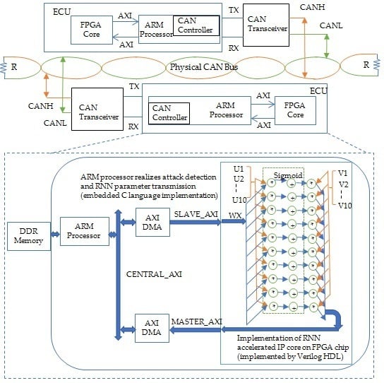
- To reduce the communication consumption, we must consider the storage position in FPGA for the weights and biases of the RNN model, which are usually near 10M. We have adopted a compromise between in-vehicle CAN communication and limited memory space in the ECU platform, where the network parameters, the matrix, or the vector are saved in external DRAM and can be read into FPGA through AXI4 stream interface. An overview of our RNN-SLTM acceleration implementation on the ZYNQ-7010 embedded platform is presented in Figure 7.
5. Experimental Results
All experiments are performed on a computer with Intel(R) Xeon(R) CPU E3-1225 V6 (3.30 GHz), 32GB DDR4.
5.1. Simulation Results
A sufficiently large amount of training data is necessary for the proposed RNN model, which we provide with simulated ECU analog signals based on Multisim Version10.0.
Mathematical models of the CAN bus and ECU transceiver are used in the simulation, where 50*5*2*6300 = 3,150,000, and samples of ECU transceiver fingerprints are produced by adjusting model parameters. Then, we adjust the model parameters to capture ECU fingerprint signal samples, which are 50*5*2*6300.
These samples represent transceiver fingerprints of 50 ECUs, each captured by 5 records, and each record has two features of a time sequence whose length is 6300. Figure 8 presents one of the simulation data based on the proposed CAN bus and ECU model. Figure 8a shows a simulation signal, Figure 8b shows a simulation signal with noise. To approximate the real physical CAN signal, we also add color noise instead of white noise in the simulation data because color noise, such as pink noise, is more suitable for the CAN bus bandwidth. While Figure 8c is the real physical signal of the ECU transmitted on the CAN bus, which will verify our proposed RNN-LSTM model.
In total, 90% of simulated data are used in training RNN-LSTM classifiers, saving the remaining 10% for evaluation. The rmsprop option is chosen for the optimizer, the loss function is chosen to be categorical_crossentropy, the epochs are set as 200, and the batch size is set as 64. We use dropout to address the overfitting issue, and the parameter of dropout is set as 0.3. We use classification accuracy to measure performance. We train the RNN network using the simulation data and obtain the loss and accuracy curve as plotted in Figure 9. In the figure, the loss is gradually decreasing and the accuracy is increasing as training epochs increase, which shows that the RNN-LSTM model works well and is closer to the label than how close the training process is to being finished. The experimental result of the proposed RNN-LSTM method are compared with other machine learning-based classifiers, which were used in previous works of literature, as shown in Table 1. In the Table 1, we can see that the RNN algorithm obtained higher accuracy than the traditional Bagged Decision Tree (BDT), Neural Network (NN), or Support Vector Machine (SVM) [4] classifiers. To train the BDT, NN, and SVM model, both time and frequency domain features are extracted. The six features of the time domain include Min, Max, Mean, Variance, Skewness, and Kurtosis, as well as the five features of the frequency domain cover Spectral-Standard-Deviation, Spectral-Skewness, Spectral-kurtosis, Spectrum-Centroid, and Irregularity-K.
5.2. Identifying the Spoofing Attack
Two types of spoofing attacks are investigated: when sender identity does not belong to any recognized ECU in the CAN network, and when transmitter identity is recognized but does not match the frame sender ID. After completing the training phase, we use two methods to classify evaluation frames. First, of the proposed method, an unlabeled set of features is tested to validate the capability to identify intrusive ECU inserted by the attacker (the first type of spoofing attack). If the pre-trained classifier fails to classify features of a frame with any recognized frame features, intrusion detection will be triggered. Second, the mismatch between classification based on frame features and frame sender ID identifies an indirect spoofing attack from an ECU hijacked by an adversary (the second type of spoofing attack). The flow chart in Figure 10 shows the proposed detection flow. Table 2 summarizes the average misidentification rates of our method as compared to [5]. Our method has shown a lower misidentification rate than the experimental results presented in [5].
5.3. Attack Accelerated Detection Based on FPGA
FPGA-acceleration is implemented on a ZYBO development board equipped with a ZYNQ-7010 all programmable system-on-chip, which integrates a dual-core ARM Coretex-A9 processor (PS) with Xilinx 7-series FPGA logic (PL) [26]. The acceleration includes the accelerator RNN IP receiving a batch of data from the PS side, performing the parallel computing in the PL part, and returning the results to the PS side. The RNN accelerator IP can perform matrix multiplication operations, which constitute the majority of operations in the testing stage of the RNN model.
The whole RNN accelerator performs 100*10*10 multiplication-addition operations in one batch. For the computing of one batch, each FPGA PE unit can perform one fixed-point multiplication and one ideal in one cycle instead of floating-point computing. There are four available AXI DMA ports and each one can send packages of 32 bits at 100 MHz and can be able to stream weights and vector values between FGPA core and external DDR memory. So, the RNN-LSTM acceleration detection is as follows: FPGA running at 100 MHz are 10.8 times faster than on the ARM core running at 650 MHz. The on-chip resource utilization is reported by Vivado(v2018.3) after implementation, which is shown in Table 3. The power consumption report, by Vivado power, for ARM (CPU0 on & CPU1 off) and FPGA is similar . These results indicate that the proposed RNN-LSTM accelerated model can be a suitable lower cost, real-time, in-vehicle application scenario.
6. Conclusions
To improve the detection of spoofing attacks on an in-vehicle CAN bus, we propose a novel and effective theoretical model of a CAN physical layer for the authentication of CAN data frame IDs. After collecting big simulation CAN signal data based on the proposed theoretical model, we apply a RNN with the LSTM unit to extract the deep features of the analog CAN signal and detect the malicious spoofing ECU nodes on an in-vehicle CAN bus. The performance of the proposed RNN-LSTM model is comparing with BDT, NN, and SVM model. The experimental result shows that RNN-LSTM works best for the detecting spoofing attack problem of an in-vehicle CAN bus. Of course, since the big training dataset is simulated, the proposed model has been verified by real in-vehicle CAN data. To satisfy the real-time restriction of CAN bus communication, we designed a hardware accelerator to process the proposed deep model. In the future, more diverse real CAN bus signals will be collected and used in validating and improving the proposed RNN-LSTM model, and the optimization of the FPGA accelerator will be designed to promote the proposed deep neural network.
Author Contributions
Writing, original draft preparation, Y.Y.; supervision, Z.D.; conceptualization, review and editing, M.T. All authors have read and agreed to the published version of the manuscript.
Funding
This work was supported by the Key Research Item for Industry in Shaanxi Province under Grant 2018GY-136.The work of Y. Yang was supported by the China Scholarship Council under Grant 201706565053.
Acknowledgments
The authors thank anonymous reviewers for their constructive comments and suggestions.
Conflicts of Interest
The authors declare no conflict of interest.
References
- Tuohy, S.; Glavin, M.; Hughes, C.; Jones, E.; Trivedi, M.; Kilmartin, L. Intra-vehicle networks: A review. IEEE Trans. Intell. Transp. Syst. 2015, 16, 534–545. [Google Scholar] [CrossRef]
- Miller, C.; Valasek, C. Remote exploitation of an unaltered passenger vehicle. Black Hat USA 2015, 2015, 91. [Google Scholar]
- Groza, B.; Murvay, P.-S.; Murvay, S. Security solutions for the controller area network: Bringing authentication to in-vehicle networks. IEEE Veh. Technol. Mag. 2018, 13, 40–47. [Google Scholar] [CrossRef]
- Avatefipour, O.; Hafeez, A.; Tayyab, M.; Malik, H. Linking received packet to the transmitter through physical-fingerprinting of controller area network. In Proceedings of the 2017 IEEE Workshop on Information Forensics and Security (WIFS), Rennes, France, 4–7 December 2017; pp. 1–6. [Google Scholar]
- Choi, W.; Jo, H.J.; Woo, S.; Chun, J.Y.; Park, J.; Lee, D.H. Identifying ECUs using inimitable characteristics of signals in controller area networks. IEEE Trans. Veh. Technol. 2018, 67, 4757–4770. [Google Scholar] [CrossRef]
- Murvay, P.-S.; Groza, B. Source identification using signal characteristics in controller area networks. IEEE Signal Process. Lett. 2014, 21, 395–399. [Google Scholar] [CrossRef]
- Choi, W.; Joo, K.; Jo, H.J.; Park, M.C.; Lee, D.H. VoltageIDS: Low-level communication characteristics for automotive intrusion detection system. IEEE Trans. Inf. Forensics Secur. 2018, 13, 2114–2129. [Google Scholar] [CrossRef]
- Woo, S.; Jo, H.J.; Lee, D.H. A practical wireless attack on the connected car and security protocol for in-vehicle CAN. IEEE Trans. Intell. Transp. Syst. 2015, 16, 993–1006. [Google Scholar] [CrossRef]
- Woo, S.; Jo, H.J.; Kim, I.S.; Lee, N.H. A practical security architecture for in-vehicle CAN-FD. IEEE Trans. Intell. Transp. Syst. 2016, 17, 2248–2261. [Google Scholar] [CrossRef]
- Zago, G.M.; de Freitas, E.P. A quantitative performance study on CAN and CAN FD vehicular networks. IEEE Trans. Ind. Electron. 2018, 65, 4413–4422. [Google Scholar] [CrossRef]
- Theissler, A. Anomaly detection in recordings from in-vehicle networks. In Proceedings of the First International Workshop, BigDap 2014, Madrid, Spain, 11–12 September 2014; p. 23. [Google Scholar]
- Kang, M.-J.; Kang, J.-W. Intrusion detection system using deep neural network for in-vehicle network security. PLoS ONE 2016, 11, e0155781. [Google Scholar] [CrossRef] [PubMed]
- Taylor, A.; Leblanc, S.; Japkowicz, N. Anomaly detection in automobile control network data with long short-term memory networks. In Proceedings of the 2016 IEEE International Conference on Data Science and Advanced Analytics (DSAA), Montreal, QC, Canada, 17–19 October 2016. [Google Scholar]
- Cho, K.-T.; Shin, K.G. Fingerprinting electronic control units for vehicle intrusion detection. In Proceedings of the 25th USENIX Security Symposium, Austin, TX, USA, 10–12 August 2016. [Google Scholar]
- Cho, K.-T.; Shin, K.G. Error handling of in-vehicle networks makes them vulnerable. In Proceedings of the 2016 ACM SIGSAC Conference on Computer and Communications Security, Vienna, Austria, 24–28 October 2016. [Google Scholar]
- Iehira, K.; Inoue, H.; Ishida, K. Spoofing attack using bus-off attacks against a specific ECU of the CAN bus. In Proceedings of the 15th EEE Annual Consumer Communications & Networking Conference (CCNC), Las Vegas, NV, USA, 12–15 January 2018. [Google Scholar]
- Song, M.; Kim, H.R.; Kim, H.K. Intrusion detection system based on the analysis of time intervals of CAN messages for in-vehicle network. In Proceedings of the 2016 International Conference on Information Networking (ICOIN), Kota Kinabalu, Malaysia, 13–15 January 2016. [Google Scholar]
- Van Herrewege, A.; Singelee, D.; Verbauwhede, I. CANAuth-A simple, backward compatible broadcast authentication protocol for CAN bus. In Proceedings of the ECRYPT Workshop on Lightweight Cryptography, Louvain-la-Neuve, Belgium, 28–29 November 2011. [Google Scholar]
- Kurachi, R.; Matsubara, Y.; Takada, H.; Adachi, N.; Miyashita, Y.; Horihata, S. CaCAN-centralized authentication system in CAN (Controller Area Network). In Proceedings of the 12th International Conference on Embedded Security in Cars (ESCAR 2014), Hamburg, Germany, 18–19 November 2014. [Google Scholar]
- Gerdes, R.M.; Mina, M.; Russell, S.F.; Daniels, T.E. Physical-layer identification of wired ethernet devices. IEEE Trans. Inf. Forensics Secur. 2012, 7, 1339–1353. [Google Scholar] [CrossRef]
- Farsi, M.; Ratcliff, K.; Barbosa, M. An overview of controller area network. Comput. Control Eng. J. 1999, 10, 113–120. [Google Scholar] [CrossRef]
- IEEE. 524-2016—IEEE Guide for the Installation of Overhead Transmission Line Conductors; IEEE: Piscataway, NJ, USA, 2017; pp. 1–162. [Google Scholar]
- Zdenek, K.; Jiri, S. Simulation of CAN bus physical layer using SPICE. In Proceedings of the 2013 International Conference on Applied Electronics, Pilsen, Czech Republic, 10–12 September 2013. [Google Scholar]
- Shao, H.; Luo, F.; Xu, J. Simulation of CAN physical layer based on SystemVision. In Proceedings of the 12th International Conference on Natural Computation, Fuzzy Systems and Knowledge Discovery (ICNC-FSKD), Changsha, China, 13–15 August 2016. [Google Scholar]
- Poudel, B.; Giri, N.K.; Munir, A. Design and comparative evaluation of GPGPU-and FPGA-based MPSoC ECU architectures for secure, dependable, and real-time automotive CPS. In Proceedings of the 28th International Conference on Application-specific Systems, Architectures and Processors (ASAP), Seattle, WA, USA, 10–12 July 2017. [Google Scholar]
- Chang, A.X.M.; Culurciello, E. Hardware accelerators for recurrent neural networks on FPGA. In Proceedings of the 2017 IEEE International Symposium on Circuits and Systems (ISCAS), Baltimore, MD, USA, 28–31 May 2017. [Google Scholar]
Figure 1.
Analog signals of two electronic control units (ECUs) transmitting the same data.

Figure 2.
The voltage values on the controller area network (CAN) bus of the recessive and dominant state.
Figure 2.
The voltage values on the controller area network (CAN) bus of the recessive and dominant state.

Figure 3.
The CAN bus model of cascaded tow port network with transmission ABCD matrix.

Figure 4.
The electric model of the transceiver.

Figure 5.
The CAN bus communication model with ECU nodes in the vehicle.

Figure 6.
The CAN bus spoofing message attack model with ECU nodes in the vehicle.

Figure 7.
An overview of the recurrent neural network with long short-term memory units (RNN-LSTM) hardware implementation.
Figure 7.
An overview of the recurrent neural network with long short-term memory units (RNN-LSTM) hardware implementation.

Figure 8.
The simulation data based on the theoretical model of the CAN bus physical layer and real brake CAN signal.
Figure 8.
The simulation data based on the theoretical model of the CAN bus physical layer and real brake CAN signal.

Figure 9.
The simulation data based on the theoretical model of the CAN bus physical layer.

Figure 10.
The simulation data based on the theoretical model of the CAN bus physical layer.


Table 1.
The testing result of simulation data based on the CAN bus.
| Machine Learning Model | Features | Average Accuracy (%) |
|---|---|---|
| BDT | Time (6 features), frequency (5 features) | 92.00 |
| NN | Time (6 features), frequency (5 features) | 95.20 |
| SVM (Linear kernel) | Time (6 features), frequency (5 features) | 96.00 |
| SVM (RBF kernel) | Time (6 features), frequency (5 features) | 96.00 |
| RNN-LSTM | deep features | 98.76 |
Table 2.
The average misidentification rate for spoofing messages.
| [5] | Our Model | |
|---|---|---|
| Average mis-identification rate (%) | 0.36 | 0.16 |
Table 3.
The field-programmable gate arrays’ (FPGA) resource utilization of the RNN acceleration model.
Table 3.
The field-programmable gate arrays’ (FPGA) resource utilization of the RNN acceleration model.
| Resource | Utilization | Available | Utilization (%) |
|---|---|---|---|
| LUT | 8777 | 17,600 | 49.87 |
| LUTRAM | 601 | 6000 | 10.02 |
| FF | 9601 | 35,200 | 25.74 |
| BRAM | 9 | 60 | 15.00 |
| DSP | 25 | 80 | 31.25 |
| BUFG | 1 | 32 | 3.13 |
© 2020 by the authors. Licensee MDPI, Basel, Switzerland. This article is an open access article distributed under the terms and conditions of the Creative Commons Attribution (CC BY) license (http://creativecommons.org/licenses/by/4.0/).
Share and Cite
MDPI and ACS Style
Yang, Y.; Duan, Z.; Tehranipoor, M. Identify a Spoofing Attack on an In-Vehicle CAN Bus Based on the Deep Features of an ECU Fingerprint Signal. Smart Cities 2020, 3, 17-30. https://doi.org/10.3390/smartcities3010002
AMA Style
Yang Y, Duan Z, Tehranipoor M. Identify a Spoofing Attack on an In-Vehicle CAN Bus Based on the Deep Features of an ECU Fingerprint Signal. Smart Cities. 2020; 3(1):17-30. https://doi.org/10.3390/smartcities3010002
Chicago/Turabian StyleYang, Yun, Zongtao Duan, and Mark Tehranipoor. 2020. "Identify a Spoofing Attack on an In-Vehicle CAN Bus Based on the Deep Features of an ECU Fingerprint Signal" Smart Cities 3, no. 1: 17-30. https://doi.org/10.3390/smartcities3010002