Worldwide Coverage Mobile Systems for Supra-Smart Cities Communications: Featured Antennas and Design


Department of Audio-Visual Engineering and Communications, ETS Ingrniería y Sistemas de Telecomunicación, Universidad Politécnica de Madrid, Calle de Nikola Tesla sn, 28031 Madrid, Spain
*
Author to whom correspondence should be addressed.
Smart Cities 2020, 3(3), 556-584; https://doi.org/10.3390/smartcities3030030
Submission received: 26 April 2020
/
Revised: 14 June 2020
/
Accepted: 29 June 2020
/
Published: 1 July 2020
(This article belongs to the Special Issue Feature Papers for Smart Cities)
Abstract
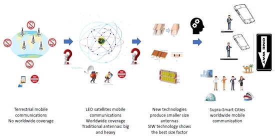
:Current terrestrial mobile communications networks can’t provide worldwide coverage. Satellite communications are expensive, and terminals are large and heavy. Worldwide mobile coverage requires the use of satellites providing an appropriate QoS, including polar regions. The analysis of the potential satellite constellations demonstrates that LEO one is the best solution. A new generation of low cost, small size, lightweight and global mobile coverage LEO satellites is emerging. The main limitation of the terminals is the antenna size factor, and innovative antennas must be developed to meet this goal. This paper investigates the technologies and techniques for designing and developing antennas aimed at LEO satellite communications in Smart Cities and beyond, which are especially beneficial for mobile communications in areas without 4G/5G coverage. The paper focuses on the terrestrial segment and future mobile devices, remarking the design constraints. In this scenario, the paper reviews the most relevant technologies and techniques used to design suitable antennas. The investigation analyses the state-of-the-art and most recent advances in the design of antennas operating in the Ku-band. The main contribution of the authors is a novel antenna design approach based on SIW technology. The antenna features are compared with other approaches, highlighting the benefits, advantages and drawbacks. As a conclusion, the proposed antenna demonstrates to be a good solution to meet the design constraints for such an application: light, low cost, small size factor.
1. Introduction
A Smart City is an area where information, technologies, infrastructures, and services are fostered to provide additional value to services that are aimed at improving the quality of life and the living-experience of inhabitants and business experience of companies. In this scenario, digital and telecommunication technologies play a major role in achieving a fully smart city. According to [1], Smart City can be taken in accordance with six characteristics: Economy, People, Governance, Mobility, Environment, and Living.
The scope of a smart city is deeper than using information and communication technologies (ICT) to optimize resources’ usage and drop current emissions. It means that all of the services and infrastructures, e.g., transportation, water and energy distribution, energy usage, street lighting, etc., are managed smartly, based on the information collected from a variety of sensors in a cooperative set. Furthermore, the interaction and response of the administration (the council) agents are required to provide the best services to different population segments, from babies to aged people, in order to guarantee a high performance and optimization.
As society evolves, smart cities must improve to cope with new needs. Smart cities are not isolated entities and a supra-smart-cities entity is now identified, and their development will be supported by new advanced communication systems providing worldwide coverage. Some of those supportive communication systems and infrastructures are currently being developed in successive stages. To provide worldwide coverage, new satellites constellations consisting of many LEO satellites, which are being launched. Furthermore, to provide such worldwide coverage, including the poles, while keeping a small size factor in mobile devices, new antennas must be designed to face current and future Smart Cities communication needs.
Despite the concrete definition we accept as most suitable or precise, a common component is a need for evolving and scalable communications. In [2], the authors highlight the key role of ICT in the development of real smart cities. Furthermore, smart cities cannot be conceived without ICT support. The authors identify an advanced global ICT infrastructure as one of the essential components of a smart city. Given that several types of wireless devices (smartphones, laptops, IoT, sensors, etc.) are being widely used and a large amount of contents is available on the Internet, network systems providing appropriate ubiquitous services, anytime, and anywhere, are needed [3].
The development of smart cities will benefit several areas of city life: education, health, environment, transportation, security, energy, business, and economy, and many research challenges are pointed out. Smart Cities need to be able to integrate themselves into national, regional, and international infrastructures. It is worthy to remark that, in order to achieve the overall goal of Smart Cities, several milestones must be reached and, in consequence, several technologies must be developed to support municipality services. The efforts should take into account both wireless infrastructures for mobile communication and wireless and wired infrastructures for fixed communication networks. Furthermore, the growing demand for ubiquitous communications to support the different services offered to the citizens in the smart city affects the technologies (WiFi, WiMAX, LTE, 4G, 5G, FTTH, etc.). Several experiments have been developed in different locations without the expected results. However, one can expect that the focus on the network side will shift to Wireless Sensor Networks, allowing for the connection between locations, everyday objects, and devices. The need for provisioning ubiquitous connectivity and reliable and real-time communications identifies satellite communications as a promising solution to support the relevant services and applications.
The requirement of global mobile coverage has driven the need for deploying a satellite constellation system to provide worldwide Internet access, especially where terrestrial systems do not, at a low cost. Access to the Internet is poor in rural areas, far from large urban centres, such as in Alaska. In recent years, several initiatives have emerged aimed at deploying constellations of low-orbit terrestrial satellites to provide connectivity and access to online services to the inhabitants of those regions, which will gradually expand the services to other regions [4]. Inclusion and information access policies spread the smart cities’ coverage.
The use of drones can be highlighted as an example of smart city range applications. They are becoming increasingly popular, despite the regulations which restrict their usage in public areas. Engineers and scientists have identified the potential of drones in civil applications, such as remote sensing, smart cities, surveillance, disaster detection, management and recovery, rescue, patrolling, aerial survey, border security, etc., among several ones. Low-cost and battery-powered drones are unable to cope efficiently with the requirements of computation-demanding applications (e.g., onboard image processing), encompassing real-time data and reliability constraints. One of their main limitations is the communication range when wireless links are used. With the appropriate infrastructure, it will be possible to manage them in areas beyond the city, e.g., in the country. It is expected that new global coverage communication systems will grant this possibility.
Currently, companies, such as OneWeb, SpaceX, Telesat, and LeoSat, are planning to use a large number of low capacity LEO (Low Earth Orbit) satellites to provide the world with broadband internet connection [5]. Because manufacturing a satellite for medium or high orbits is very expensive, low-cost air satellites, such as balloons, and mini-satellites flying at the Earth’s low-orbit, have recently appeared [6,7]. Besides, given the small size (volume) and low weight, their cost for launching is low.
While (mobile) smartphones for terrestrial communication systems are becoming smaller and smaller (except for screen size), devices that are linked to those satellites constellations are claimed to show reduced size factor too. Even in the case of drones introduced above a low size, low weight, a low-cost antenna is required to avoid heavy and large drones, the need for more powerful engines, and to reduce the overall cost.
At this point, it is worthy to mention the massive machine-type communions (mMTC), also known as the Internet of Things (IoT), which are characterized by a low complexity and the availability of extremely cheap devices that are capable of generating and exchanging information. When considering their small size, the traffic generated by these IoT devices can have a significant impact on the network load. Therefore, satellite communications can alleviate network traffic through backhaul, or provide continuity to services in those cases where the terrestrial network does not have coverage. This use case can be divided into two groups depending on the type of application, as it supports the satellite and how the available sensors are distributed over the ground [8,9,10,11].
NB-IoT devices are one of the most promising technologies to support mMTC communications within 5G communications usage scenarios. In the context of an IoT network with global coverage, low orbit satellites (LEO) will play a very important role given the low propagation losses of these links, as well as the low complexity of the devices [9].
In [12], the authors analyse the problem of critical machine-type communications (cMTC), which is one of the key characteristics identified in future 5G communication systems. The authors provide WFs (Waveform) multi-carrier traditions. They identify and analyse a set of indicators to see how this type of system works. Among others, the most relevant indicators they analyse are out-of-band radiation, spectral performance, bit and carrier synchronization, end-to-end latency of the physical layer, arrogance, complexity of the transceiver, and fundamental parameters to guarantee QoS.
M2M communications are having a rapid growth in mobile networks where they provide the opportunity to satisfy the quality of service (QoS) requirements for massive machine communication systems (mMTC) with limited capabilities. Therefore, one of the problems that the mobile network must face concerns the massive use is the allocation of available resources. In order to guarantee this quality, in [13] the authors propose a fast and efficient algorithm that exploits the periodicity of MTC traffic based on the persistent allocation of resources.
Given the expected demand for services supported by mMTC using satellite communication, the development of cost-effective devices with a tiny size is required, and the antenna is the main component impacting the size factor.
In this investigation, the operation frequency bands are those commonly used in cubesat constellations, as well as the spaceX and One Web systems, i.e., 10.7–11.7 GHz band for RX (down-link) and 14–14.5 GHz band for TX (up-link) [14].
The remaining part of this paper is organized as follows. Section 2 summarizes the main features of the various types of satellite constellations, remarking those characteristics, which can affect worldwide mobile communications’ reliability and performance, and highlights the ongoing developments to provide worldwide coverage, pointing out their differences. Section 3 states the design constraints that are focused on the terrestrial segment requirements, given that they affect the antenna design. Afterwards, Section 4 introduces the most relevant types of antennas and design methods for satellite communications. In Section 5, the main results of the investigation are discussed, while Section 6 discusses the findings and highlights the advantages and drawbacks. Finally, Section 7 draws the main achievements and remarks on the paper contribution.
2. Satellites Constellations
Current geostationary satellites, which orbit along the equator, have difficulties in providing service coverage at the highest latitudes (polar regions) due to the elevation angle needed to transmit/receive the signal guaranteeing it will reach the receiver, as shown in Table 1.
The most important factors in establishing reliable links using LEO satellites are, among others:
- Ability to adjust the frequency of the receiver to compensate and track the frequency offset of the received signal band due to the Doppler effect during the satellite’s run over the entire path.
- Ability to track the satellite, not only across the sky (azimuth or compass indication and elevation angle over the horizon), but also very important, keeping the polarization angle aligned with the polarization of the satellite.
- Sufficient gain in the receiving antenna system, as described in Table 1, to guarantee proper performance.
GEO satellites constellations are not useful for deploying a global coverage in Smart Cities and wider areas due to the low angle required for transmission/reception, as shown in Table 1. Using LEO constellation for global coverage shows some drawbacks. One of them is that possible orbits are limited and can be saturated. Furthermore, there exist some issues in some regions of the space due to the possibility of fostering a large number of satellites in a small area of the space, given that each constellation has many satellites. Nevertheless, at the short term, it is not much likely such situation given, despite it is produced when orbiting at low altitude, situated in a region called Van Allen belt which is affected by strong radiation, it is at a distance about 900 km away and a large number of orbits are available and 60.000 LEO satellites can operate without mutual disturbance.
Table 2 summarizes the advantages and drawbacks that satellite communications show for the various types of constellations, i.e., satellites’ orbit height and relative speed. It is worthy to note that LEO is the constellation which shows the lowest delay. This is due to the orbit height, the lowest, making the link path distance earth-to-satellite the shortest. In consequence, it is quite appropriate for live transmission (video, audio, etc.) and low latency services (video-conference, gaming, e-health, etc.). Furthermore, due to its shortest link, the signal suffers a lower attenuation and the required antennas gain is lower and the transmit power as well.
Regarding the drawbacks, the main design constraint is due to the large Doppler effect due to the relative speed of LEO satellites. Moreover, satellite tracking is required to make the antenna pointing to the satellite located in the earth mobile station is linked to, due to the relative movement of the satellites. This is because omnidirectional antennas are preferred, which requires less accurate satellite tracking or even no tracking. The features described above makes LEO constellations the most appropriate for global coverage mobile telephony and multimedia services.
The development and innovation in technologies for satellites are in constant and fast progress. The demand for current and new applications based on satellite technologies is also continuously growing (https://www.esa.int/Our_Activities/Telecommunications_Integrated_Applications/Satellite_frequency_bands).
Satellites are mainly known because of their applications to the mass market, as radio-communications and broadcasting (satellite-TV), but they are also applied to weather maps for forecast, universe observation (i.e., astronomy), location systems, and much more.
Due to the long list of frequency bands that are assigned to satellites communications services, these bands have been designated by letters to easily refer to them. Table 3 shows the different frequency bands. Our main focus addresses Ku and Ka bands for LEO satellite communications.
A key reason to shift radio-communication bands to higher frequencies is the availability of wider bandwidths and higher transmission speeds. On the other hand, the effect of disturbances as rain fade (signal attenuation due to rain, snow or ice) becomes notorious. Given this competition, which demands developing new application further communication satellites constellations are being required denser, and a serious congestion problem could arise soon, especially at low-frequency bands. This fact makes new investigation to address novel technologies enabling higher frequency operation.
The novel technology known as Substrate Integrated Waveguide (SIW) allows for designing and implementing many microwave components, including slot array antennas on planar circuits instead the traditional implementation using normal waveguides, which, in many applications, are not appropriate due to the resulting height in the design process, and SIW-based antennas show the same advantages. Even more, the SIW-based design leads to implementations with very low weight and at a low implementation cost, making SIW-antennas more affordable to spread the global coverage satellites communications in the mass market, a dream that seems closer.
2.1. Design Parameters for Satellite Communications
The design of a satellite communications links is based on the same parameters than any other radiofrequency link. The concrete values and characteristics depend on the type of constellation given the have particular features. There are a number of factors that affect satellite links, which can be divided into two categories: the conduit factors and the content factors. The former include parameters, such as the ground-space and space-ground distance, the effect on the propagation signal, the quality of the earth station equipment, and the impact of the frequency band of interest. The content factors are mainly related to the type of messages to be transmitted, and the type of devices involved. Basically, the link balance relates the transmitted power with the received power to guarantee the quality and reliability of the communication.
An important property of satellite communications is that they are in direct line of sight. Therefore, the parameters that correspond to a communication in free space are those that are used, to which must be added the particular disturbances suffered by satellite communications. The essential parameters that characterize a transmission are antenna gain, beamwidth, path attenuation in free space, and the link power equation. The design must also take into account the noise of the communication system and how its effect on the radiofrequency link is quantified, for which terms, such as noise power, noise temperature, noise figure, and figure of merit are used. The carrier-to-noise ratio (C/N) is one of the parameters used to define the quality of the communication link. There are particular aspects that relate to the equipment used and that influence the link design, such as the sensitivity of the receivers. Table 4 shows the key performance indicator (KPIs) recommended by the 3GPP for 5G.
If we compare the link design for GEO, MEO, and LEO satellites, we will find parameters with different values due to the different characteristics of the link, in particular the distance, which will affect the attenuation in free space. Other parameters to take into account, depending on the application, are the delay produced by the link length and the latency. Table 5 shows the main parameters that are used to develop a satellite communication project.
Table 6 draws the design parameters for three examples based on the 3GPP work [15]—satellites operating in the Ka band are much more susceptible to adverse weather conditions than those operating in the Ku band, and especially those operating in the C band. Working on platforms at higher frequencies allows the use of smaller on-board antennas, which provides the possibility of mounting multi-antenna systems, that is, arrays, on satellites.
GEO satellites are those that incorporate larger antennas to produce the energy that is required to guarantee the quality of communication, typically 12 m and even 25 m in diameter, to provide adequate gain. One of the main disadvantages of GEO systems is latency, due to its greater distance from the ground. On the other hand, LEO low-orbit satellites are the other extreme in terms of antenna size. Given that they use orbits of the order of 700 to 1400 km, the losses of free space produced are quantified around 30 dB, much less than those that occur in GEO satellites. The low latency is practically negligible, in most applications, and the antenna size is really small and it can be powered by a small-size solar panel according to the size of the satellite. In the case of MEO medium-orbit satellites, they have orbits between 10,000 and 12,000 km around Earth. The distance from Earth as compared to GEO satellites is quite less, the problems due to latency are not as relevant. A GEO satellite typically must have an antenna approximately 10 to 12 m in diameter to provide the necessary gain. The antenna required by a satellite would be less than 50 cm. With the necessary power requirements, it would be possible to make an exchange between antenna size and transmitted power, since the antennas required in the case of LEO satellites are very small.
Regarding the receiving end, one of the most relevant parameters is the G/T ratio, which depends on both the antenna gain and the losses in the same typical mobile terminal, the EIRP requirement is 0.5 w. The G/T ratio must be see at least −25 dB/K. If a higher power is required, no more than a higher receiver sensitivity to buy with the requirements before writing the signal to noise ratio. Practical systems using GEO, MEO, and LEO satellites have similar requirements for EIRP and G/T, but the antennas are very different from those used in mobile devices, as well as the power ranges.
Table 7 shows the various types of antennas use in the satellite space segment antennas for different earth coverage strategies in GEO satellites. Shaping the beam allows for decreasing the required Tx power but increasing the antennas complexity. In MEO and LEO satellites, it does not make sense shaping the space segment antennas’ beam given they are continuously moving and they try to cover all ofthe visible area.
2.2. Worldwide Coverage Developments
In this section, we introduce the main features of each constellation and compare them. Worldwide mobile coverage is generating high expectation to potential users, and three main projects have been identified to compete in this market: OneWeb (Ku&Ka-band System), SpaceX (Ku&Ka-bands System), and Telesat (Ka-band System). Table 8 shows and compares the main features of the three constellations.
3. Terrestrial Segment Requirements
In this section, the terrestrial segment requirements regarding Tx and Rx antennas gain, Tx power, and tracking systems are analysed.
Massive LEO-constellation, such as OneWeb and Space-X, extend mobile operator network coverage to wider areas around the world, including the oceans and polar regions, using nano-satellites as a relay. This capability is enabled using two different terrestrial segments: the gateway and the user terminals. Gateway stations receive the requested data from users through satellites constellation and send back the proper data-packet.
Additionally to the basic connectivity functionality, Gateway stations also provide Telemetry, Tracking and Command System (TT&C) for the whole constellation. Usually, the Gateway consists of big fixed antennas operating in the Ka-band, wide bandwidth, and high power. For example, in the OneWeb constellation, the Gateway uses a TDM transmission scheme for a 250 MHz wideband carrier, and obtain two-times frequency re-use, by use of orthogonal circular polarization.
Once the carrier is received as an RHCP and the data is extracted, users’ terminals transmit bursts of data SC-TDMA/FDMA in short periods of time and on a narrow-band carrier (1.25 to 20 MHz) in order to minimize the Tx peak power. It’s required because terminals, including the LHCP-TX-antennas, are small-size and light, to make them real portable devices, and the dissipated power should be minimized. Moreover, battery life must be extended as long as possible. This can be accomplished by reducing the required Tx power.
As it was remarked above, LEO-constellations nano-satellites turn around the world at high speed, and handovers frequency is high given that each satellite is tracked by the terminal during few seconds, and it is needed to guarantee the communication service. Minimizing the problem requires using terrestrial steerable dish-antennas which, by using an appropriate DOA algorithm, can track the satellite optimizing the link performance and battery consumption. However, steerable dish-antennas require complex mechanical mechanisms to point the antenna to the satellite. On the other hand, phased array antennas use beamforming array processing techniques [16], to achieve the appropriate radiation pattern. Figure 1 draws a typical phase array antenna that consists of 8 × 8 antennas.
4. Ku-Band Antennas Design Techniques
Currently, there is a growing demand for antenna systems aimed at satellite communications, either GEO or LEO constellations, with low weight and small size factor to be used in mobile communications with global coverage and wide bandwidth. In this kind of applications, where those features are a strong requirement, planar antenna systems could be a good option to fit those specifications.
This section introduces the main design techniques used to construct antennas operating in the Ku-band. Usually, to achieve the required specifications, i.e., radiation pattern gain, directivity, aperture, etc., the antennas are combined to set-up arrays. First, we briefly introduce some state-of-the-art examples and, afterwards, the next sections introduce the types of antennas that are most commonly used in satellite communications, with special focus on the Ku-band transmission/reception.
4.1. Combining Devices for Antenna Arrays
Grouping a set of antennas, commonly known as antenna array, is a common strategy to increase the overall antenna gain and properly shape the radiation pattern. Array antennas can be implemented while using various basic antenna elements, such as patches, slots, monopoles, dipoles, horns etc. [17,18]. To meet the requirements regarding gain and radiation/reception pattern, the amplitude and phase of the signals that are fed into each basic element are modified to achieve the expected radiation pattern, including main lobe(s) pointing angle, width (aperture), gain, etc.
There is an increasing demand for satellite communications with world-wide coverage and spreading the satellite frequency band is requested. The C band use is at the limits and, in consequence, the demand for communications in the Ku band is augmenting progressively because of the possibility of using wider bandwidths. It is also well known that some communication satellites operate simultaneously in both C and Ku bands, offering a better service. In consequence, appropriate design techniques and proper technologies must be developed to operate at the same time at both bands and, specifically, appropriate antennas approaches must be addressed for C and Ku simultaneous communications while analysing the particular disturbances affecting each band [8].
In [19] the authors propose, introduce and analyse a six-port junction based on the SIW (Substrate Integrated Waveguide) technology. To achieve the design constraints, the authors convert the SIW element into an equivalent waveguide with a rectangular profile in order to apply conventional design techniques for such waveguides. The junction can be applied for different purposes. Based on that simple device, the authors face the design of two SIW basic components: a 3 dB hybrid coupler and a divider. Afterwards, these components are used to design the six-port junction circuit working in the frequency band at 24 GHz. Subsequently, it was implemented and measured to corroborate the results obtained in the simulation phase. It was found that the six-port junction introduced in this paper fits the requirements. This element can be used in the construction of arrays of planar antennas.
In [11], the authors introduce the design of a Nolen matrix which could be used in the implementation of devices and systems based on multi-layer SIW techniques. This technology could lead to the implementation of a beamforming network topology with compact size factor. Specifically, the authors introduce a new broadband coupler based on two-layers SIW technology. It is worthy to remark the features of the designed device. The coupler shows a wide dynamic range within a considerable bandwidth, i.e., about 12 GHz in the Ku band. Among other beamforming structures where the component could be used (e.g., Butler matrices), the authors propose its use for the implementation of matrices aimed at multiple beamforming. Additionally, the authors introduce the design of a low-losses two-layers waveguide transition based on multiple layers topology SIW technology. The results obtained in this investigation could be extended to larger structures, e.g., a Nolen matrix.
In [20], the authors analyse the design and implementation of via and aperture transition structures aimed at interconnecting three-dimensional (3-D) integration of substrate integrated waveguides. The methodology used is based on the description of electrical equivalent circuits to develop a parametric analysis to discuss the error met as compared to full-wave simulations. Furthermore, the achieved models for both via and aperture transitions are implemented and measured to validate the results.
4.2. Primary Focus Antenna (PFA)
Figure 2 shows the primary focus antennas, also known as satellites dish, have a front profile that is a perfect circle. This antenna is completely symmetric, and the side profile is a parabola, as a difference with offset antennas, wave-frontier toroidal antennas, or double focus antennas.
In this kind of antennas, the focal point is in the middle point of the shaped plate. The antenna LNB faces the dish, mounted in the vertical axis in the spotlight of the set, in order to receive at such point the signal reflecting on the parabola, concentrating while adding coherently. The size of this kind of antenna is typically over 1.2 m in diameter. Table 9 shows the main advantages and disadvantages of this type of antenna.
Mesh, Cassegrain, and Gregory are other subfamilies with a different implementation of the primary focus antennas. In the case of Mesh dish, the plate is substituted by some kind of metal grid, avoiding the accumulation of water, snow, etc. This implementation is lighter than the others.
4.3. Offset Antenna
Figure 3 draws the offset antennas are composed of a reflector that is an oval-shaped section of a paraboloid, i.e., the effective antenna surface is not round, it is an ellipse. Additionally, the focal point is not situated at the centre of the plate, it is shifted to one side a certain offset. The main advantage which exhibits this technology exhibits is that the antenna reflector surface is not shadowed by the LNB (from the satellite perspective).
The shape of the reflector and set-up shows and additional deployment advantage: it is not easy that snow or any other substance accumulates on the reflector that would disturb the signal making the antenna gain drop drastically. Due to the reflector shape, it seems the antenna is not oriented appropriately as it is not oriented facing the satellite straight, as in the primary focus antenna. It is shifted about 25 downwards (in the vertical axis). Nevertheless, the offset plate seems as circular with the horizontal diameter in the plane of view from the satellite. This disposition makes the feeder does not produce a shadow on the reflector. Multibeam, Cassegrain and Gregory are other types of offset antennas, which are often used in satellite communications.
4.4. Wave-Frontier Toroidal Antenna
Another type of antenna shown in Figure 4, which in shape is similar to the Gregory reflector, is the called dual reflector toroidal antennas. The main difference is the key concept used to design this antenna: the sub-reflector of the toroidal antenna is part of the virtual toroid while the main reflector is shaped like an ellipsoid.
This antenna uses a convex-concave shaped sub-reflector, i.e., it is convex in one of the planes while in the other it is concave. The main drawback of this type of antenna is the complex mathematical computation required to its design and the mechanical implementation. New technologies and CAD (Computer-Aided Design) make these tasks much easier and accurate. Size and weight make difficult the use of these antennas for worldwide mobile communications.
4.5. Double Focus Antenna —Offset Gregory
This antenna is shown in Figure 5. The structure of this antenna includes an additional sub-reflector that improves its features showing a higher efficiency and gain. For example, the efficiency of a double focus offset Gregory with an offset of 90 cm is equivalent to that achieved by a regular offset antenna whose offset is 110 cm.
One of the drawbacks of Gregory offset antennas is the higher implementation cost. On the other hand, the design with much more severe specifications provides around 12% of additional gain. Despite its size being reduced as compared to the regular offset antenna, it is not a realistic candidate for world-wide coverage mobile communications. As a design example of this kind of antenna, Table 10 introduces the most relevant specifications (Technical data of a Masterfocus/Fibo antenna).
4.6. Planar Antennas
Figure 6 shows the panar antennas are an alternative antenna design which is based on the technique known as planar matrix. This kind of antennas is appropriate for mobile global coverage satellite reception due to its compact design, as compared to the aforementioned antennas, and the reduced visual impact.
As the resulting flat antenna requires very little mounting space (it does not require an external LNB), it is preferred for those applications where the are physical limitations, i.e., there is no possibility of using larger antennas or in the case where regular satellite reception dishes antennas are not allowed by regulations, or in applications where the antenna must be transported. The most relevant advantage of this antenna is in the fact that it is the least annoying.
It is important to highlight that the antenna will only provide a well-received signal level if it is located in the main area of the desired satellite coverage footprint area. In other words, it should be used in constellations where satellites transmit signal at high power. One of the main disadvantages of the planar matrix-based antenna is the limitation to the reception of a single satellite or a constellation of grouped satellites, like Astra, in 19.2 East or Hotbird in 13.0 East. Table 11 remarks the main features of this antenna.
In [21], the authors introduce the design of a wide-band antenna for Ku band satellite communications, at a centre frequency 11.725 GHz. The antenna is designed using the multilayer planar slot array technology and simulated to obtain a reference of the expected features. The designed array is composed of slot antennas elements, where each one is optimized by minimizing the return losses at the centre of the band. The design is intended to the reception of both orthogonal linear polarization. The antenna is aimed at receiving satellites signals from the Turksat, i.e., in the area around Turkey. For these satellites, the effective isotropic radiated power is about 54 dBw. The authors propose as design specification a minimum gain of 27 dBi for the whole antenna structure.
In [22] the authors show the design and implementation of a planar Ku band antenna. The antenna is aimed at satellite communications and in particular, it’s appropriate for receiving satellite TV channels in the Turkey region. The paper shows the key facts concerning the design and implementation stages. Furthermore, the main features of the antenna are measured to verify the results obtained in the simulation phase.
A wide bandwidth multilayer patch antenna design and analysis are introduced in [23]. The wide bandwidth is achieved when stacking a patch over the fed patch, which is coupled in gap structure. The bandwidth of the constructed antenna based on layered patches is inverse to the gap size. Increasing the gain means decreasing the gap, and the construction of the antenna becomes more difficult and inaccurate. A test setup is performed in order to corroborate the simulation results. Table 12 shows the measured values of the main features of the antenna.
In [24] the authors introduce a novel high gain patch antenna array that is based on a dual-band dual circularly polarized aimed at satellite communications for vehicle applications. To construct the array, a set of 16 linearly polarized dual-band elements where the array is backed with a new frequency-selective-surface-integrated artificial magnetic conductor ground, obtaining promising results. This device is implemented under the constructed array. In consequence, it performs two relevant tasks; on one side it acts as a normal reflector, which increases the foresight gain of the array and, on the other side, it provides the ability to generate the dual circular polarized feature. The electromagnetic waves reflected by the frequency-selective-surface-integrated artificial magnetic conductor produces a rotation of either 90 or 270 with respect to the array electromagnetic waves that are directly radiated to the upper sphere at two frequency bands. In consequence, this behaviour enables the dual-band dual circular-polarized radiation performance. The behaviour shown by this antenna array seems to be completely distinct from most of the previously designed counterparts, whose design technologies are based on either the disturbance produced on the stacked patch or an external excitation network. The antenna array is designed, simulated, and after implementation, it is tested to validate the introduced approach.Table 13 highlight the main features shown by this antenna.
The so-called microstrip patch array antennas are very popular in satellite communication applications [25]. This kind of antennas shows some advantages in comparison to traditional antennas. Different techniques can be developed to implement small size patch array antennas. In [25], the authors introduce the design and implementation of a microstrip array antenna with distribution factor 2 × 2. Table 14 shows the main features of the antenna. The array antenna was aimed at satellite communications in X band and Ku bands applications. The simulation results and measurements validate the proposed antenna showing appropriate behaviour.
In [26], the authors introduce a sub-array for the construction of wide-angle scanning antenna array for satellite communications in the Ku frequency band. The proposed approach is based on the use of waveguide continuous transverse stubs, and the antenna array is composed of two sub-arrays which consists of a set of sixteen horn antennas. A regular waveguide binary power divider is used to excite the sub-array consisting of waveguide continuous transverse stubs. The authors analyse the design constraints and compute the parameters that fix the requirements to construct the continuous transverse stubs for the targeted scanning antenna array. The main features of the proposed sub-array are as follows:
- compact structure,
- lightweight,
- construction is feasible,
- high efficiency,
- aperture efficiency: >55% (for the whole band), and
- beam-scanning range of ±90.
The beam-scanning range described above is obtained by mechanical rotation of the sub-arrays around its axes, the same angles. The scanning antenna approach is suitable for satellite communication terminals and radar systems.
The design of a so-called Vivaldi antenna array is introduced in [27]. The antenna shows a high gain, good directivity properties, and it can operate in ultra-wide-bandwidth. The array antenna is mainly aimed at applications concerning synthetic aperture radar (SAR), in concrete, for small surveillance satellites. The antenna design introduces as novelty modifying the structure of the proposed antenna in order to achieve higher performance, i.e., improving the radiation pattern properties and electrical characteristics: directivity, gain, return losses (S11), voltage standing wave ratio (VSWR), impedance, and antenna efficiency. The methodology used to design the array antenna followed a standard procedure for similar designs. Formerly, a single antenna element is characterized, designed, and optimized. For this task, a genetic algorithm was used. Table 15 provides the main features of the Vivaldi antenna after optimization. The antenna structure optimization is aimed at improving the performance, i.e., the resolution capabilities, in applications concerning synthetic aperture radar.
The simulation results are validated by the construction of a prototype and measurement of the main characteristics. It is concluded that the proposed antenna seems to be suitable for applications involving high-resolution synthetic aperture radar.
A novel multi-segment rectangular dielectric resonator antenna is introduced in [28] for satellite communications. The proposed antenna is aimed at wide bandwidth operation, specifically for military and satellite applications in the frequency bands X and Ku. The approach that is introduced by the authors is based on an FR4 notched rectangular dielectric resonator antenna where a high permittivity insert of Alumina to improve the performance, and it is set into a segment of U-shaped Rogers 5880. A 50 Coaxial feeder exciting the setup is used to achieve a high gain across the whole aimed wide bandwidth. It is worthy to note that the proposed approach shows a wide impedance bandwidth (about 130%). The peak gain is measured at 11.2 GHz with a value of 8.5 dBi. The approach shows a radiation efficiency on average of 92.1% for the whole impedance bandwidth, with a radiation pattern omnidirectional in both axes.
A hat-feed based 0.8-meter reflector antenna is proposed in [29]. The antenna is aimed at satellite communications in the Ku band, and specifically for mobile applications. The authors designed and simulated the antenna to analyse its performance. The antenna setup is composed by a Sub-1M ring focus reflector antenna, where a self-supporting dielectric hat-feed is added. The choice of the hat-feed element was based on the radiation pattern key properties: low side-lobe and low cross-polarization. To achieve the best performance, the authors studied and optimized the hat-feed in order to achieve a wide bandwidth operation. A prototype of the antenna was constructed and measured in the near-field after simulation to corroborate the results, which are shown in Table 16.
In [30], it is analysed and designed, implemented and test a transmit array antenna with high-gain dual-band and dual-polarized. The antenna was designed to operate in satellite communications. The single basic element consists of two novel loop elements combination which is interlaced to built the basic element to achieve the dual-band operation. The proposed approach shows an advantage: the response at transmission is nearly independent at both frequencies for the interlaced loop elements. The constructed three-layer dual-band element shows the performance that is summarized in Table 17.
In [31], an antenna that consists of a rectangular grating waveguide slot array is analysed. Furthermore, the paper introduces a design methodology for antenna aimed at application concerning satellite communications receivers. The antenna design targets a wide bandwidth in the Ku band for satellite communications. The radiating slots with a rectangular grating waveguide behave in the same way than a frequency-selective transmission line does and, at the same time, performs some additional filtering. Adjusting the rectangular grating waveguide parameters design parameters it is feasible to adjust/tune both the operating bandwidth and the out of band rejection. A prototype aimed at the band was designed with eight-slot rectangular grating waveguide slot array antenna that serves to test the antenna and check the matching between the theoretical, simulation and measured features, and verify the proper performance. The main features of the proposed antenna are compared with those corresponding to a conventional eight-slot rectangular waveguide slot array antenna. The measurements taken on the antenna demonstrate that the antenna performance is appropriate to operate in the band between frequencies 12.25 GHz and 12.75 GHz. Table 18 show the main features of the proposed antenna as compared to the traditional one.
The proposed antenna has a better out-of-band rejection performance. Furthermore, 14.8 to 21.3 dB additional realized gain suppression is achieved in the range 14.0–14.5 GHz when compared to the regular antenna, which is equivalent to an extra out of band filtering. Fabrication tolerance can produce milled metallic sheets provoking slight shape distortions that could result in high errors at some frequencies.
A reconfigurable meta-surface beam-steerable reflector is proposed in [32]. The resulting antenna is aimed at satellite communications, where the whole Ku band would be covered. The design of the antenna is optimised to manage a 300 MHz bandwidth. The authors proposed a novel approach based on a new kind of electromagnetic bandgap element to construct the reflector where the change of the capacitance of the metasurface reflector of each unit is carried out by using varactors. In this way, it is feasible the spatial control of the reflected beam phase. Although this technique is well described in scientific publications, especially in the sub 6 Ghz band, there are few references concerning the application of this approach to reflectors designed for the X-band. It also feasibly applied this technique to higher band, e.g., the Ku band, leading to design where the unit cell size is smaller than lower bands. In such a case, it should be considered that the varactor size is comparable to the area of the metasurface unit cell. Consequently, noticeable absorption and scattering effects affect the signal. These issues are analysed and displacing the varactor to the opposite side of the proposed reflector seems to be an appropriate approach for mitigating the absorption and scattering. This solution does not affect the lumped elements structure that models the device. In consequence, it is conclude that the introduced approach leads to a low-cost solution of the voltage-controlled reflector surface for Ku-band. Furthermore, as result of the analysis, design, implementation, and test of the antenna, fabrication hints are remarked to achieve the expected features for the Ku band reflector showing a wide dynamic stirring range performance. The simulations conducted along the investigation demonstrate that the proposed approach exhibits a wide bandwidth for incident signal (on the surface of the reflector), both orthogonal and off-orthogonal.
In [33], the authors propose a method for enhancing the antenna gain in the case of circularly polarized (CP) magneto-electric dipole antenna (MEDA). The antenna is designed to operate in the full Ku band. In order to feed the CP MED antenna, it is also designed and implemented a single-layer partially reflecting surface that is constructed on a substrate containing arrays of metal patches that are printed on both the top and bottom forms a Fabry–Perot resonator antenna. This investigation also took into consideration the impact of the symmetrical patch and analysed and compared the following types in order to compare and optimize the reflective phase property:
- double printed circular,
- square,
- circular-ring,
- square-ring patches, and
- single printed circular patch.
After comparing the result achieved with each type, the authors choose the circular patch one given the exhibited gentle reflective phase gradient, i.e., the final overall gain achieved by the CP MEDA is improved in the whole addressed frequency band. The authors optimized and implemented a prototype, and measured the main features of the antenna to verify the theoretical and simulation results, obtaining the results shown in Table 19. The conclusion is that the introduced method seems to be an appropriate choice to implement satellite communication wide CP bandwidth antennas.
In [34], the authors introduce the design and analysis of a circularly polarized dielectric resonator antenna (DRA) suitable to satellite communications. The designed antenna shows a wide bandwidth and, at the same time, low axial ratio values. The dielectric resonator antenna is the basic element used to compose the overall antenna, which is constructed by stacking several DRA. The antenna is finally fed at the bottom of the stack by a substrate integrated waveguide coupling slot. Low permitivity substrate is used in order to construct the antenna. On this substrate, several high permitivity dielectric strips are layered to form the antenna structure. This physical construction results in a wide bandwidth and high gain. An improvement introduced in this design is that, instead of using just one dielectric strip, a couple of dielectric strips are layered on the coupling slot constructed with 45 inclination. This set-up makes the generation of the circular polarization required for the transmission/reception easier. In this case, the design decision was aimed at generating three circular polarization modes which are closely coupled. With the aim of smoothing the application in the antenna array, it is further introduced the design of a cavity-backed antenna. The authors proposed implementing, measuring, and testing a sub-array prototype in order to verify the design and simulation results, with the main features being shown in Table 20.
A reflect-array antenna that is specifically designed for satellite communications at the Ku band applications composed of elements is introduced in [35], where the basic element is a single layer structure that is linearly polarized. This antenna is aimed at communications at 12.5 GHz (within the Ku band). The tests implemented to verify the antenna features demonstrate that this reflect-antenna shows a high gain and a good behaviour of the phase properties. It is conclude that this antenna is appropriate to be used as a reflector. The methodology to achieve the best performance was based on the design of several basic elements, evaluate each one in order to choose those with superior features and, afterwards, the array is constructed. To feed the antenna array, a source patch is used, which is positioned at the appropriate distance ().
4.7. SIW Technology Based Antennas
SIW (Substrate Integrated Waveguide) technology consists of integrating a waveguide into a dielectric substrate, presenting characteristics that are similar to those of a waveguide filled with dielectric material with the same height, permittivity, and equivalent width.
In traditional rectangular waveguides, waves are confined within the waveguide and, given the dielectric, the air losses affecting waves in these guides are minimal, but with disadvantages, such as the difficulty of integration with other means, such as weight and size. In a rectangular waveguide based on SIW, the waves are confined within the conductive walls and travel through the dielectric material of which it is filled. This type of technology is compatible with existing PCB and LTCC [36,37] manufacturing techniques and, in turn, allows the design and construction of guides in the microwave and millimetre-wave range with high-quality factor, low cost, and easy integration with planar circuits, such as power dividers, filters, and antennas [19,38].
Planar antennas can be easily integrated on the SIW surface, in order to place complex shaped-slots to obtain multi-band operation and circular polarization. In [39], two radiant split ring slots are placed on a SIW cavity-backed. Figure 7 dr<ws this kind of antenna. The cavity can be excited by using a coaxial connector producing two orthogonal linearly polarized radiations, whose linear superposition achieves an RHCP diagram. The cavity is made on FR-4 substrate, and its size is mm to operate at 11 GHz:
- impedance bandwidth of ,
- 3 dB AR bandwidth of ,
- peak gain of 4.4 dBi.
Traditional slot arrays can also be implemented while using SIW. Their behaviour is similar to waveguide antennas. Slots can form a travelling-wave or resonant array, depending on whether the array is either ended by a matching load or by a short-circuit respectively. An example of resonant slot array on SIW is presented in [40], where it manufactured SIW on Rogers-RT3010, with four longitudinal slots, 11 mm length to resonate at 5 GHz. The antennas are placed orthogonal to each other at the edge of a nano-satellite and they are fed through a 90 hybrid to generate the desired circular polarization.
As an alternative, they propose the design of a Half-Mode Substrate Integrated Waveguide (HMSIW) [41]. The proposed HMSIW structure is similar to the SIW one, but, in HMSIW, there is only one row of vias to construct the required electric wall, as shown in Figure 8, while the other side is kept open-ended to constitute a virtual magnetic wall. Furthermore, the same behaviour than a conventional SIW is obtained by using a half-width structure. The authors construct an HMSIW smaller new nano-cube antenna. Table 21 compares the most relevant features of the SIW and. HMSIW antennas.
5. Results
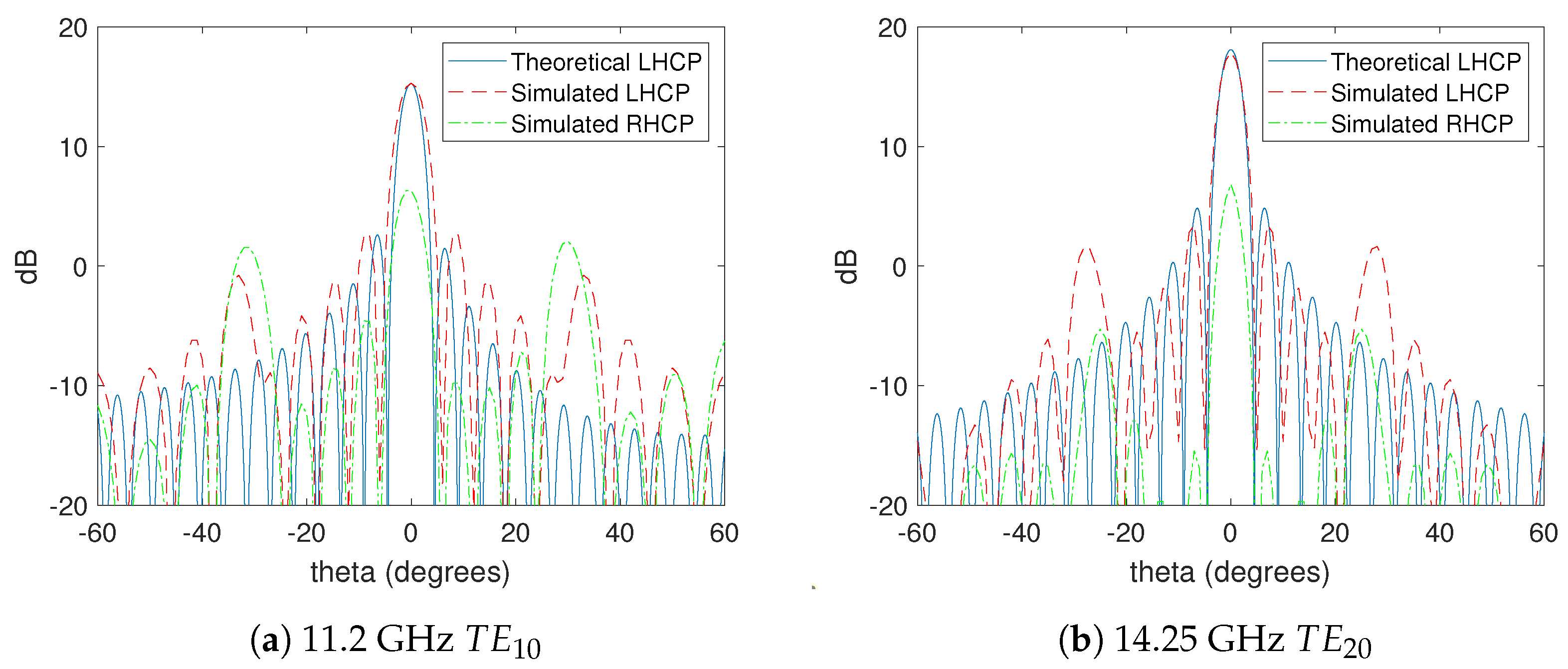
As aforementioned, travelling-wave arrays can also be used to increase the bandwidth, among other features. Because the SIW behaviour is very close to waveguides, more than one mode can propagate. These features are exploited by the authors to design a dual-band circular polarized antenna slot array in the Ku-band. Selected bands, which are independently tunable, are 10.7–11.7 GHz for RX side and 14–14.5 GHz for TX link. Because and are phase-shifted 90, circular polarization can be achieved by using a set of slots: transversal and longitudinal, at the same place. In the downlink (RX frequencies), propagates and the design includes slots placed to enable surface currents to produce radiation. Figure 9 shows the radiation pattern on different planes. In the up-link (TX-band), the mode excites another set of two slots. The magnetic field and the surface currents do not perturb each other, as shown in Figure 10. In consequence, the set of slots can be independently tuned. Figure 10 shows the magnetic field while Figure 11 depicts the surface currents. The two sets of slots can be seen as a single LHCP Radiator block. Co-polar and Cross-polar diagrams are shown in Figure 9, and the main features are summarized in Table 22.
The dual-band feeder is designed using a three-layer stack-up. A transition from microstrip-to-SIW is placed on the top face with a bandpass filter centred at RX-band, while at the bottom face we place a 180 phase shifter to excite mode into SIW at TX-band. Figure 12 shows the resulting structure.
Once the single radiator block element is designed, we can construct an array by uniformly distributing basic elements, where a matched-end is provided for both propagation modes by using a proper termination as shown in Figure 13.
A dual-band antenna with circular polarization working at Ku-band can be aimed to act as transceiver in the ground-segment for novel LEO constellations such as OneWeb, SpaceX and other Cubesat constellations. For this purpose, slots in Figure 11 are replicated 20 times along the Y-axis to enhance directivity, as shown in Figure 14. Slots working at TE are 5.5 mm-long, whereas TE mode works with 4.5 mm-slots. To make sense of the satellite application, each couple of slots is placed at different distances to obtain the same beam pointing for both bands (12.5 mm for RX and 11.8 mm for TX).
If the structure of Figure 14 were replicated again ten times along X-axis, allowing electronic steering for satellite-tracking, directivity would increase above 25 dBi, which can be considered as a good value for LEO-satellites links. Regarding OneWeb constellation [7], portable transceivers for user-ground-segment are suggested to be 30cm-dish antennas. This novel constellation deploys 720 satellites in 18 1200 km-orbits and, for the user-link, provides 16 beams with 250 MHz-bandwidth each for downlink and 1.5–20 MHz for uplink. Although the proposed SIW antenna is smaller and not as directive as the reflector one, due to the circular polarization, SIW provides 3 dB to the satellite-link-budget, whose receiver antenna for user link holds a dB. Assuming a 50W-HPA for the user terminal, a comparison between the suggested dish-antenna and the proposed one is shown in Table 23.
6. Discussion and Future Trends
In this section, we summarize the main findings of our investigation on antennas for worldwide coverage satellite communications.
Traditional satellite antennas are not appropriate for designing the terminals for the future global communications mobile system based on LEO satellite constellations, due to their size factor, i.e., they are not hand/pocket devices.
Planar antennas have marked the pathway to give a solution to size concerns. Beyond these antennas, SIW technology-based antennas show more appropriate features to be integrated into the future worldwide coverage mobile communications supported by the emerging LEO satellites constellations.
SIW technology embeds in the substrate different RF devices, including waveguides and slot antennas. It is also useful for feeder, combiner, divider, and lamped elements design.
Table 24 compares the most significant features of the antennas analysed along with this investigation versus the antenna design proposed by the authors. Some parameters were not provided by designers.
There are many techniques to design antennas, but few of the mare appropriate to design antennas for terminals to be used for worldwide mobile communications, due to size, weight, and steering capabilities to operate in the Ku-band linking LEO satellites. Conventional antennas, like primary focus, offset, or double focus, are not suitable for personal terminals. Planar antennas are more appropriate than traditional techniques due to the lower weight and smaller size factor, and good performance. SIW technology is providing high-performance antennas and is currently the most promising technology for designing global coverage future mobile terminals.
Satellites Optical Communications
The emerging alternative to satellite radio communications is the satellite optical communications, which are attracting the attention of scientists and engineers. Nowadays, the scientific community is starting to experience a new revolution in satellite communications: optical communications, which are promising unexpected data rates transmission, data security, and resilience to meet commercial requirements in the next ten years. An example of serious initiatives in such direction is the ScyLight (Secure and Laser communication technology) programme promoted by the ESA which is aimed at supporting the research, development, innovation, and evolution of optical communication technologies mainly based on laser and offers researchers flight opportunities for in-orbit verification of prototypes (https://www.esa.int/Our_Activities/Telecommunications_Integrated_Applications/ScyLight).
The frequency bands used in satellite communications suffer from some congestion and the bottleneck effect due to the growing demand for satellite communications services. Beaconless acquisition using a laser link means that lower orbits, which are congested, are avoided, and that mobile terminals can be lighter, with lower power consumption, providing greater accuracy and safety than a conventional radio link.
Among the benefits of optical links, it is worth highlighting the benefits of avoiding interferences and detection, due to the difficulty of exploring the space by searching for laser beacons to intercept. It results in being more difficult than in radio frequency communications. Optical links are also capable of exchanging large amounts of data, more than the existing alternatives. Accordingly, in the case of new technologies and applications, such as Big Data, it becomes a technology of capital importance for the development of future services.
Under the ScyLight program, the ESA is conducting a system and market study to analyse how optical communications technologies can be developed and applied more efficiently to meet the demand. The industry can also participate in this ESA initiative, for example, to apply for ScyLight programs by submitting a proposal to request assistance for any research and development project, even being able to perform real tests in orbit.
7. Conclusions
Smart Cities is a fact that must be faced during the next decade to transform cities into smart. The Smart Cities concept includes the management fo the different services offered to citizens, including health, education, administration, energy, transportation, etc. These services are supported by ICT. Appropriate infrastructures are required to provide ubiquitous access to services and information, in a worldwide context. Satellite communications seem to be the way to achieve worldwide mobile communications and ubiquitous access to services and data. Among the various satellite constellation types, LEO is identified as the most appropriate for different reasons, among them, lower satellites construction and launch costs, smaller antennas size, and lower transmission power (which affects battery life).
Hence, the main motivation for this investigation is the need for providing worldwide coverage for mobile communications, even in polar regions, and terrestrial mobile networks cannot offer such a feature. The main limitation of the terminals is the antenna size factor, and novel antennas must be developed. Hence, this paper has analysed and compared the most relevant features and design methods of antennas aimed at worldwide mobile communications using LEO satellite constellations. The main constraints for the integration of those antennas in the future terminals for global coverage communications are size, weight, and steering capabilities.
Three systems, which are currently being deployed, were taken as references: OneWeb, SpaceX, and Telesat. These constellations operate in the same frequency band in the terrestrial segment (Ku-band). The operation requirements were analysed to establish the antenna design constraints. A novel design technique, named SIW (Substrate Integrated Waveguide), was introduced due to its integration capability.
The main contribution of the authors is the conception of a novel antenna based on the new SIW technology, operating in the Ku-band, aimed at global coverage mobile communications through LEO satellites. The features of the designed antenna were compared with the ones from other attacks. Benefits, advantages, and drawbacks of the proposed antenna were highlighted. The proposed antenna demonstrates to be a beneficial solution to meet the design constraints for such an application: appropriate performance, light, low cost, and small size factor.
Although the novel antenna seems to be appropriate for the described purpose, further investigation is needed to obtain antennas with smaller size.
Author Contributions
Both authors contributed equally. Both authors have read and agreed to the published version of the manuscript.
Funding
This research received no external funding.
Conflicts of Interest
The authors declare no conflict of interest.
Abbreviations
The following abbreviations are used in this manuscript:
| AR BW | Axial Ratio Bandwidth |
| e6MBB | enhanced Mobile BroadBand |
| CP | Circular Polarization |
| DL | Downlink |
| ESA | European Space Agency |
| GEO | Geostationary Earth Orbit |
| HEO | High Earth Orbit |
| HMSIW | Half-Mode Substrate Integrated Waveguide |
| FFTH | Fibre to the Home |
| ICT | Information and Communicatio Technologies |
| ITU | International Telecommunication Union |
| KPI | Key Performance Indicator |
| LEO | Low Earth Orbit |
| LNB | Low Noise Block |
| MEO | Medium Earth Orbit |
| SAR | Synthetic Aperture Radar |
| SIW | Substrate Integrated Waveguide |
| UE | User Equipment |
| UL | Uplink |
| VSWR | Voltage Standing Wave Ratio |
| WiMax | Worldwide Interoperability for Microwave Access |
References
- Correia, L.M.; Wünstel, K. White paper: Smart Cities Applications and Requirements. Works European Technology Platform: Expert Working Group Smart Cities Applications and Requirements. Technical Report 2011-05-20. 2011. Available online: https://grow.tecnico.ulisboa.pt/wp-content/uploads/2014/03/White_Paper_Smart_Cities_Applications.pdf (accessed on 29 June 2020).
- Mardacany, E. Smart cities characteristics: Importance of buit environments components. In Proceedings of the IET Conference on Future Intelligent Cities, London, UK, 4–5 December 2014; pp. 1–6. [Google Scholar]
- Kaneko, K.; Kawamoto, Y.; Nishiyama, H.; Kato, N.; Yamamoto, S.; Yoshimura, N. An intelligent routing scheme effectively utilizing mass storage embedded on satellites to mitigate network congestions. In Proceedings of the 16th ACM International Conference on Modeling, Analysis & Simulation of Wireless and Mobile Systems, Barcelona, Spain, 3–8 November 2013; pp. 167–172. [Google Scholar] [CrossRef]
- The Number of Satellites Orbiting Earth Could Quintuple in the Next Decade. Available online: https://www.technologyreview.com/2019/06/26/755/satellite-constellations-orbiting-earth-quintuple/ (accessed on 29 June 2020).
- Del Portillo, I.; Cameron, B.G.; Crawley, E.F. A Technical Comparison of Three Low Earth Orbit Satellite Constellation Systems to Provide Global Broadband. In Proceedings of the 69th International Astronautical Congress 2018, Bremen, Germany, 1–5 October 2018. [Google Scholar]
- Nagpal, L.; Samdani, K. Project Loon: Innovating the connectivity worldwide. In Proceedings of the 2017 2nd IEEE International Conference on Recent Trends in Electronics, Information & Communication Technology (RTEICT), Bangalore, India, 19–20 May 2017. [Google Scholar]
- Barnett, R.J. OneWeb Non-Geostationary Satellite System; FCC: Washington, DC, USA, 2013. [Google Scholar]
- Sun, H.; Zhang, F.; Jia, C. Research on Key Technologies of C/Ku Dual-Band Satellite Communication. In Proceedings of the 2019 International Conference on Robots Intelligent System (ICRIS), Haikou, China, 15–16 June 2019; pp. 149–151. [Google Scholar] [CrossRef]
- Kodheli, O.; Andrenacci, S.; Maturo, N.; Chatzinotas, S.; Zimmer, F. An Uplink UE Group-Based Scheduling Technique for 5G mMTC Systems Over LEO Satellite. IEEE Access 2019, 7, 67413–67427. [Google Scholar] [CrossRef]
- Arouk, O.; Ksentini, A.; Taleb, T. Group Paging-Based Energy Saving for Massive MTC Accesses in LTE and Beyond Networks. IEEE J. Sel. Areas Commun. 2016, 34, 1086–1102. [Google Scholar] [CrossRef]
- Ali, A.; Coccetti, F.; Aubert, H.; Fonseca, N.J.G. Novel multi-layer SIW broadband coupler for Nolen matrix design in Ku band. In Proceedings of the 2008 IEEE Antennas and Propagation Society International Symposium, San Diego, CA, USA, 5–11 July 2008; pp. 1–4. [Google Scholar] [CrossRef]
- Medjahdi, Y.; Traverso, S.; Gerzaguet, R.; Shaïek, H.; Zayani, R.; Demmer, D.; Zakaria, R.; Doré, J.; Ben Mabrouk, M.; Le Ruyet, D.; et al. On the Road to 5G: Comparative Study of Physical Layer in MTC Context. IEEE Access 2017, 5, 26556–26581. [Google Scholar] [CrossRef]
- Hussien, Z.H.; Sadi, Y. Flexible radio resource allocation for machine type communications in 5G cellular networks. In Proceedings of the 2018 26th Signal Processing and Communications Applications Conference (SIU), Izmir, Turkey, 2–5 May 2018; pp. 1–4. [Google Scholar]
- Du, M.; Xu, J.; Dong, Y.; Ding, X. LTCC SIW-Vertical Fed-Dipole array fed by a microstrip network with tapered microstrip-to-SIW transitions for wideband millimeter-wave applications. IEEE Antennas Wirel. Prop. Lett. 2017, 16, 1953–1956. [Google Scholar] [CrossRef]
- ETSI TR 138 913 V14.2.0 (2017-05, 5G; Study on Scenarios and Requirements for Next Generation Access Technologies (3GPP TR 38.913 version 14.2.0 Release 14)). Available online: https://www.etsi.org/deliver/etsi_tr/138900_138999/138913/14.02.00_60/tr_138913v140200p.pdf (accessed on 29 June 2020).
- Johnson, D.H.; Dudgeon, D.E. Array Signal Processing: Concepts and Techniques; Simon & Schuster, Inc.: New York, NY, USA, 1992. [Google Scholar]
- Volakis, J. Antenna Engineering Handbook, 4th ed.; McGraw-Hill Professional: New York, NY, USA, 2007. [Google Scholar] [CrossRef]
- Milligan, T.A. Modern Antenna Design; John Wiley & Sons, Ltd.: Hoboken, NJ, USA, 2005. [Google Scholar]
- Xu, X.; Bosisio, R.G.; Wu, K. A new six-port junction based on substrate integrated waveguide technology. IEEE Trans. Microw. Theory Technol. 2005, 53, 2267–2273. [Google Scholar] [CrossRef]
- Suntives, A.; Abhari, R. Transition Structures for 3-D Integration of Substrate Integrated Waveguide Interconnects. IEEE Microw. Wirel. Components Lett. 2007, 17, 697–699. [Google Scholar] [CrossRef]
- Yagli, A.F.; Gokten, M.; Kuzu, L.; Ertok, H.H.; Gulgonul, S. An antenna array for Ku band satellite reception. In Proceedings of the 2015 31st International Review of Progress in Applied Computational Electromagnetics (ACES), Williamsburg, VA, USA, 22–26 March 2015; pp. 1–2. [Google Scholar]
- Gokten, M.; Kuzu, L.; Yagli, A.F.; Gulgonul, S.; Demircioglu, E. A planar Ku band antenna for satellite communications. In Proceedings of the 2016 IEEE/ACES International Conference on Wireless Information Technology and Systems (ICWITS) and Applied Computational Electromagnetics (ACES), Honolulu, HI, USA, 13–18 March 2016; pp. 1–2. [Google Scholar] [CrossRef]
- Ansari, J.A.; Yadav, N.P.; Mishra, A.; Singh, P.; Vishvakarma, B.R. Analysis of Multilayer Rectangular Patch Antenna for Broadband Operation. Wirel. Pers. Commun. 2012, 62, 315–327. [Google Scholar] [CrossRef]
- Zhu, J.; Yang, Y.; Li, S.; Liao, S.; Xue, Q. Dual-Band Dual Circularly Polarized Antenna Array Using FSS-Integrated AMC Ground for Vehicle Satellite Communications. IEEE Trans. Veh. Technol. 2019, 68, 10742–10751. [Google Scholar] [CrossRef]
- Borel, T.T.S.; Yadav, A.R.; Shah, U. Design of Rectangular Patch Array Antenna for Satellite Communication. In Proceedings of the 2019 3rd International Conference on Computing Methodologies and Communication (ICCMC), Erode, India, 27–29 March 2019; pp. 759–764. [Google Scholar] [CrossRef]
- Litinskaya, Y.A.; Polenga, S.V.; Stankovsky, A.V.; Hudonogova, A.D.; Salomatov, Y.P. A Subarray for Ku-Band High-Gain Scanning Antenna Based on CTS Waveguide. In Proceedings of the 2019 Radiation and Scattering of Electromagnetic Waves (RSEMW), Divnomorskoe, Russia, 24–28 June 2019; pp. 285–288. [Google Scholar] [CrossRef]
- Hanbay, E.; Aydemir, M.E. High Gain Ultrawide Band Vivaldi Antenna Design for Mini/Micro Satellite Synthetic Aperture Radar Applications. In Proceedings of the 2019 9th International Conference on Recent Advances in Space Technologies (RAST), Istanbul, Turkey, 11–14 June 2019; pp. 491–495. [Google Scholar] [CrossRef]
- Vasisht, P.; Chattoraj, N.; Chandra, R.; Rajak, N. A Novel Compact Ultra Wide-Band MSRDRA for X- and KU-BAND Applications. In Proceedings of the 2019 URSI Asia-Pacific Radio Science Conference (AP-RASC), New Delhi, India, 9–15 March 2019; pp. 1–4. [Google Scholar] [CrossRef]
- Dwivedi, M.K.; Sharma, A.K. Compact Reflector Antenna System for Ku-Band Satcom on the Move (SOTM). In Proceedings of the 2019 6th International Conference on Signal Processing and Integrated Networks (SPIN), Noida, India, 7–8 March 2019; pp. 254–257. [Google Scholar] [CrossRef]
- Aziz, A.; Yang, F.; Xu, S.; Li, M.; Chen, H. A High-Gain Dual-Band and Dual-Polarized Transmit array Using Novel Loop Elements. IEEE Antennas Wirel. Propag. Lett. 2019, 18, 1213–1217. [Google Scholar] [CrossRef]
- Yuan, W.; Liang, X.; Zhang, L.; Geng, J.; Zhu, W.; Jin, R. Rectangular Grating Waveguide Slot Array Antenna for SATCOM Applications. IEEE Trans. Antennas Propag. 2019, 67, 3869–3880. [Google Scholar] [CrossRef]
- Rotshild, D.; Abramovich, A. Wideband reconfigurable entire Ku-band metasurface beam-steerable reflector for satellite communications. IET Microw. Antennas Propag. 2019, 13, 334–339. [Google Scholar] [CrossRef]
- Cao, W.; Lv, X.; Wang, Q.; Zhao, Y.; Yang, X. Wideband Circularly Polarized Fabry–Perot Resonator Antenna in Ku-Band. IEEE Antennas Wirel. Propag. Lett. 2019, 18, 586–590. [Google Scholar] [CrossRef]
- Yang, W.; Sun, W.; Tang, H.; Chen, J. Design of a Circularly Polarized Dielectric Resonator Antenna With Wide Bandwidth and Low Axial Ratio Values. IEEE Trans. Antennas Propag. 2019, 67, 1963–1968. [Google Scholar] [CrossRef]
- Bhaskaran, R.; Srinivasan, P.; Sethuraman, L.; Habiba, H.U. Design of Ku Band Reflectarray Antenna Using Novel Half Ellipse Elements. In Proceedings of the 2018 6th Edition of International Conference on Wireless Networks Embedded Systems (WECON), Rajpura, India, 16–17 November 2018; pp. 41–43. [Google Scholar] [CrossRef]
- Yan, L.; Hong, W.; Hua, G.; Chen, J.; Wu, K.; Cui, T. Simulation and experiment on SIW slot array antennas. IEEE Microw. Wirel. Compon. Lett. 2004, 14, 446–448. [Google Scholar] [CrossRef]
- Cheng, S.; Yousef, H.; Kratz, H. 79 GHz Slot Antennas Based on Substrate Integrated Waveguides (SIW) in a Flexible Printed Circuit Board. Antennas Propag. IEEE Trans. 2009, 57, 64–71. [Google Scholar] [CrossRef]
- Malipatil, S.; Mallikarjun, D.S.; Hadalgi, P.; Hunagund, P. Study on Integrated Waveguide Slot Antennas. Int. J. Eng. Sci. Technol. 2011, 3, 5912–5915. [Google Scholar]
- Huang, J.; Lei, D.; Jiang, C.; Tang, Z.; Qiu, F.; Yao, M.; Chu, Q.X. Novel Circularly Polarized SIW Cavity-Backed Antenna with Wide CP Beamwidth by Using Dual Orthogonal Slot Split Rings. Prog. Electromagn. Res. C 2017, 73, 97–104. [Google Scholar] [CrossRef] [Green Version]
- Maged, M.; Elhefnawi, F.; Akah, H.; El-Akhdar, A.; El-Hennawy, H. Design and Realization of Circular Polarized SIW Slot Array Antenna for CubeSat Intersatellite Links. Prog. Electromagn. Res. Lett. 2018, 77, 81–88. [Google Scholar] [CrossRef] [Green Version]
- Maged, M.; Elhefnawi, F.; Akah, H.; El-Akhdar, A.; El-Hennawy, H. Hal-Arrow Slot Antenna for Inter-satellite communications. Prog. Electromagn. Res. Lett. 2018, 79, 121–128. [Google Scholar] [CrossRef] [Green Version]
Figure 1.
Phase array antenna.

Figure 2.
Primary focus antenna.

Figure 3.
Offset antenna.

Figure 4.
Toroidal antenna.

Figure 5.
Double focus antenna—Offset Gregory.

Figure 6.
Planar antenna array: Ku-band, 16 × 16, single circularly polarized (CP).

Figure 7.
SIW Cavity-backed CP Antenna.

Figure 8.
SIW antenna for nano-cubes.

Figure 9.
Radiation patterns.

Figure 10.
H-field distribution along the antenna.

Figure 11.
Surface currents.

Figure 12.
Dual-mode feeder.

Figure 13.
Detailed array layout.

Figure 14.
Array Factor radiation pattern for LHCP and RHCP at YZ plane.


Table 1.
Satellites constellations at different orbits.
| Name | Number | Altitude (km) | Angle () | |
|---|---|---|---|---|
| LEO | ISS | 1 | 360–400 | 51.64 |
| Orbcomm | 29 | 785 | 45 | |
| GlobalStar | 48 | 1414 | 52 | |
| Iridium | 66 | 765 | 86 | |
| MEO | GPS | 24 | 20,200 | 55 |
| Glonass | 24 | 19,132 | 64,8 | |
| HEO | Molniya | 4 | 504–39.863 | 63,4 |
| GEO | Astra | 16 | 35,788 | 0 |
| Hispasat | 7 | 35,788 | 0 | |
| Goes | 4 | 35,788 | 0 | |
| Meteosat | 3 | 35,788 | 0 | |
| Intelsat | 63 | 35,788 | 0 | |
| Inmarsat | 12 | 35,788 | 0 | |
| Thuraya | 3 | 35,788 | 0 |
Table 2.
Pros and cons of using different satellites orbit.
| LEO | MEO | GEO | HEO | |
|---|---|---|---|---|
| Delay | very low | 100–200 ms | 250 ms | 250 ms |
| Congestion | No | No | Yes | No |
| Earth tracking | Low gain, hemispheric or omnidirectional pattern | Low gain, hemispheric or omnidirectional pattern | Fixed antenna | Fixed antenna |
| Power and gain | Low Tx power | Low Tx power | High gain antennas at satellite | High gain antennas at satellite |
| Doppler effect | High | Medium | No | Low |
| Launch cost | Medium | Medium | Very high | High |
Table 3.
Satellite communications frequency bands.
| Band | Frequency Range (GHz) | Up-Link (GHz) | Down-Link (GHz) |
|---|---|---|---|
| L | 1–2 | 1.61–1.66/1.93–2.01 | 1.452–1.61 |
| S | 2–4 | 2.025–2.11 | 2.29–2.50 |
| C | 4–8 | 5.925–6.452 | 3.7–4.20 |
| X | 8–12 | 7.925–8.425 | 7.25–7.75 |
| Ku | 12–18 | 12.75–13.25/14–14.5 | 10.7–12.75 |
| Ka | 27–404 | 27.5–31 | 17.2–21.2 |
Table 4.
3GPP 5G KPIs.
| Parameter | Value |
|---|---|
| Peak data rate | 20 Gbps for DL |
| 10 Gbps for UL | |
| Peak spectral efficiency | 30 bps/Hz for DL |
| 15 bps/Hz for UL | |
| Control plane latency | 10 ms |
| User plane latency | eMBB: 4 ms for UL |
| 4 ms for DL | |
| URLL: 0.5 ms for UL | |
| 0.5 ms for DL | |
| Mobility interruption time | 0 ms |
| Spectrum efficiency | 3× (eMBB) |
| Reliability | URLLC: (32 bytes with a user plane latency of 1 ms) |
| eV2X: (300 bytes with a user plane latency of 3–10 ms) | |
| UE battery life | mMTC: beyond 10 years, 15 years desirable (200 bytes UL per day, 5 Wh) |
| Connection density | 1,000,000 device/km in urban environment |
| Mobility | 500 km/h |
Table 5.
Satellite system parameters.
| Parameter | |
|---|---|
| Transmit Power and Bit Energy | |
| Effective Isotropic Radiated Power | |
| Equivalent Noise Temperature | |
| Carrier-to-Noise Density Ratio | |
| Bit Energy to Noise Density Ratio | |
| G/Te Ratio | |
| Illumination Level and Power Flux Density | |
| C/Ts Ratio |
Table 6.
Satellite examples.
| Attributes | Example-1 | Example-2 | Example-3 |
|---|---|---|---|
| Carrier Frequency | Around 1.5 or 2 GHz for both DL and UL | Around 20 GHz for DL; Around 30 GHz for UL | Around 40 or 50 GHz |
| Duplexing | FDD | FDD | FDD |
| Satellite architecture | Bent-pipe | Bent-pipe, On-Board Processing | Bent-pipe, On-Board Processing |
| Typical satellite system positioning in the 5 G architecture | Access network | Backhaul network | Backhaul network |
| Bit Energy to Noise Density Ratio | Up to 2 @ 10 MHz | Up to 2 @ 250 MHz | Up to 2 @ 1000 MHz |
| Satellite Orbit | GEO, LEO | LEO, MEO, GEO | LEO, MEO, GEO |
| UE Distribution | 100% Outdoors | 100% Outdoors | 100% Outdoors |
| UE Mobility | Fixed, Portable, Mobile | Fixed, Portable, Mobile | Fixed, Portable, Mobile |
Table 7.
Satellite space segment antennas for earth coverage strategies.
| Type | Features |
|---|---|
| Global | global coverage: One downlink antenna beam |
| simple antenna | |
| small data capacity | |
| transparent repeaters | |
| Spot beams | separated beams |
| simple antenna | |
| better data capacity | |
| transparent repeaters | |
| Multiple spot beams | separated & contiguous |
| complex antennas (Beam Forming Networks) | |
| High data capacity (frequency re-use) | |
| comm payload has regenerative repeaters | |
| on Board Processing & routing capabilities | |
| Dual polarization | bverlapped beams |
| increased data capacity (twice frequency re-use) | |
| higher interference: uplink & downlink |
Table 8.
Comparison of the main features of OneWeb, SpaceX, and Telesat.
| OneWeb | SpaceX | Telesat | |
|---|---|---|---|
| Constellation | LEO | LEO | LEO |
| Height (km) | 1200 | 550 | 745–1000 |
| No. Satellites | 720 | 4425 | 117 |
| Elevation angle | 55 | 40 | 20 |
| Full coverage | yes | yes | yes |
| Sat. weight (Kg) | 150 | 227 | 100 |
| Freq. band | Ku&Ka | Ku&Ka | Ku |
| User terminal antenna | Phase array | Phase array | low profile ESA or traditional mechanically steered |
| Antenna size | cm | 1 m wide | from 65 cm |
| Max. Data rate (Gbps) | 9.97 | 21.36 | 38.68 |
| Latency (ms) | 25 | 40 | 10–15 |
Table 9.
Advantages vs. disadvantages for a primary focus antenna.
| Advantages | Disadvantages |
|---|---|
| It is more tolerant to construction inaccuracies. | Potential efficiency and gain drop due to water or snow accumulation on the reflector. |
| Special care must be taken in the setup to accurately mount the antenna.n. | |
| The LNB is situated in the central focus is blocking a large part of the received signal. |
Table 10.
Features of the Gregory offset antenna.
| Feature | Value |
|---|---|
| Antenna diameter | cm |
| Antenna efficiency | 82% |
| Cross polarization insulation | ≤−35 dB |
| VSWR | <1.12 |
| Beam width (3 dB) | 1.57 |
Table 11.
Features of the planar matrix-based antenna.
| Feature | Value |
|---|---|
| Shape | square |
| Edge width | 35–55 cm |
| Type of LNB | integrated universal single or universal twin |
| Frequency range | 10.7–12.75 GHz (Ku band) |
| Polarization | vertical/horizontal |
| Gain | comparable to that with an offset of 60cm approximately |
| Weight | 2.5 Kg–max. 7 kg |
Table 12.
Features of the wide bandwidth multilayer patch antenna.
| Feature | Value |
|---|---|
| structure | multilayer patch |
| frequency | Ku band |
| bandwidth | 42.65% |
| gain (3 dB) | 6.08 dB |
| beamwidth | about 92 |
Table 13.
Features of the high gain patch antenna array.
| Feature | Value |
|---|---|
| frequency band | 12 GHz |
| structure | 16 linearly polarized dual-band elements |
| impedance bandwidth (at −10 dB) | from 7.8 GHz to beyond 8.5 GHz |
| axial ratio (at 3 dB, lower band -right-hand CP-) | 8.15–8.35 GHz |
| axial ratio (at 3 dB, higher band -left-hand CP-) | 14.2–14.8 GHz |
Table 14.
Features of the microstrip array antenna.
| Feature | Value |
|---|---|
| frequency band | 12 GHz |
| gain | 8.98 dB |
| directivity | 10.83 dB |
| efficiency | 83% |
| bandwidth | about 693.6 MHZ (5.9%) |
| structure | 2 × 2 linear array |
| substrate | FR4 |
| thickness | 1.6 mm |
| dielectric constant | 4.4 |
Table 15.
Features of the Vivaldi antenna.
| Feature | Value |
|---|---|
| frequency band | Ku |
| gain | 8.98 dB |
| size | 44 × 49 mm |
| substrate | Rogers Duroid 5880 |
| dielectric constant | 2.2 |
| structure | 16 elements (4 × 4) planar array |
| average gain | 18 dB |
| side lobe level | below −20 dB |
| gain peak | 19.4 dB at 10 GHz |
| Vivaldi | high efficiency |
Table 16.
Features of the hat-feed based 0.8-m reflector antenna.
| Feature | Value |
|---|---|
| bandwidth | 30% (Ku band) |
| antenna efficiency | above 70% |
| cross-polarization (on-axis) | better than 30 dB |
| Rx gain | 30 dBi (10.94 GHz–12.75 GHz) |
| ITU-580.6 | Tx band (13.75–14.5 GHz) |
Table 17.
Features of the three-layer dual-band and dual-polarized antenna.
| Feature | Value |
|---|---|
| operation band | Ku (12.5–14.25 GHz) |
| phase-range | 300 |
| downlink peak gain | 30.2 dBi |
| insertion losses | <2 dB |
| uplink peak gain | 32.3 dBi |
| aperture efficiency in downlink | 38% |
| aperture efficiency in uplink | 46% |
Table 18.
Features of the proposed antenna vs. conventional antenna.
| Feature | Proposed Antenna | Conventional Antenna |
|---|---|---|
| antenna efficiency | 68.3–88.8% | 66.9–84.6% |
| −15 dB bandwidth | 6.4% (12.03–12.83 GHz) | 6.0% (12.05–12.80 GHz) |
| 12.25–12.75 GHz performance | good | good |
| reflection coefficients (Tx) | −0.80 dB | −1.93 dB |
| gain peak (Rx) | 15.82 dBi | 16.36 dBi |
| measured realized gain (Tx) | −10.77 to −22.16 dBi | 4.07 to −0.84 dBi |
Table 19.
Features of the circularly polarized-magneto-electric dipole antenna (CP-MEDA) antenna.
| Feature | Value |
|---|---|
| 10 dB return-loss bandwidth | about 54% (11.7–19.8 GHz) |
| 3 dB gain bandwidth | 42.3% (11.7–17.2 GHz) |
| 3 dB axial-ratio bandwidth | about 29.3% (12.4–16.8 GHz) |
| overlapped bandwidth of the three | 29.3% |
| maximum CP gain | 11.45 dBic at 14 GHz |
| gain enhancement | about 2.1–5.2 dB (compared with the unloaded type) |
Table 20.
Features of the dielectric resonator antenna (DRA) antenna.
| Feature | Value |
|---|---|
| operation band | Ku |
| inclination | 45 |
| sub-array size | |
| impedance bandwidth | |
| 1 dB AR bandwidth | |
| peak gain | 15.1 dBi |
Table 21.
Features of the SIW antenna vs. HMSIW antenna.
| Feature | Proposed Antenna | Conventional Antenna |
|---|---|---|
| AR Bandwidth | 100 MHz | 220 MHz |
| Impedance bandwidth | 70 MHz | 200 MHz |
| Dimensions | cm | cm |
| Gain (dBi) | 5 dBi | 5.5 dBi |
| Radiation efficiency | 58% | 93% |
Table 22.
Features of the dual band circular polarized antenna.
| Feature | RX-Band | TX-Band |
|---|---|---|
| Bandwidth | 9% | 3.5% |
| Dimensions | 10 × 10 cm | 5 × 7.7 cm |
| Directivity | 5.6 dBi | 6 dBi |
| Decoupling losses | 0.4 dB | 0.2 dB |
| Slot length | 6 mm | 5 mm |
Table 23.
Features of conventional dish antenna and proposed one for OneWeb.
| Feature | Dish Antenna | Proposal |
|---|---|---|
| Type | Reflector | Planar |
| Polarization | Linear | CP |
| Dimensions | 30 cm-diameter (0.07 m) | 18 × 22.4 cm (0.04 m) |
| D(dBi) | RX:30/TX:32 dBi | RX:26.5/TX:28.5 dBi |
| Efficiency | 0.5–0.7 (Typical) | >0.5 |
| Decoupling losses | 3 dB | <0.8 dB |
| 22.1 dB | 21 dB | |
| Steering | Mechanical | Electronic |
Table 24.
Features comparison: proposed SIW antenna vs. existing antennas.
| Antenna | Type | Freq. (GHz) | Num. | Size (cm) | AR BW (3 dB) (%) | Effic. (%) | Peak Gain (dBi) | Polariz. |
|---|---|---|---|---|---|---|---|---|
| [21] | multilayer planar slot array | Ku | - | 10 | 30 | 30 | orthog. linear | |
| [22] | T-shaped microstrip patch antenna | Ku | 10 × 10 | − | 2 | 28 | 30 | orthog. linear |
| [26] | wide-angle scanning antenna array | Ku | 2 × 15 | 50 × 45 | 40 | 55 | 16.75 | single |
| [27] | Vivaldi Antenna | X,Ku | 4 × 4 | 4.4 × 4.9 | 20 | 70 | 19.4 | dual |
| [28] | hat-feed based reflector antenna | Ku | 1 | 80 | 30 | 70 | 30 | single |
| [30] | array antenna with high-gain dual-band and dual-polarized | Ku | - | - | 4.2/6.9 | 38/46 | 32.2/32.3 | dual |
| [31] | rectangular grating waveguide slot array | Ku | 8 | 9 × 9 | 1.2 | 68.3/88.8 | 15.82 | single |
| [33] | CP MED | Ku | - | - | 29/43 | 29.3 | 11.45 | dual |
| [34] | Dielectric resonator antenna | Ku | 4 | - | 20 | 15.1 | CP | |
| [39] | radiant split ring slots-SIW cavity | 10.40 | - | - | 1.54 | 10.8 | 4.4 | CP |
| [41] | HMSIW | 5 | 1 × 2 | 5 × 7.7 | 40 | 93 | 5.8 | CP |
| Authors proposal | SIW | Ku | 4 | 10 × 10 | 20 | 70 | 6 | dual |
© 2020 by the authors. Licensee MDPI, Basel, Switzerland. This article is an open access article distributed under the terms and conditions of the Creative Commons Attribution (CC BY) license (http://creativecommons.org/licenses/by/4.0/).
Share and Cite
MDPI and ACS Style
Benavente-Peces, C.; Herrero-Sebastián, I. Worldwide Coverage Mobile Systems for Supra-Smart Cities Communications: Featured Antennas and Design. Smart Cities 2020, 3, 556-584. https://doi.org/10.3390/smartcities3030030
AMA Style
Benavente-Peces C, Herrero-Sebastián I. Worldwide Coverage Mobile Systems for Supra-Smart Cities Communications: Featured Antennas and Design. Smart Cities. 2020; 3(3):556-584. https://doi.org/10.3390/smartcities3030030
Chicago/Turabian StyleBenavente-Peces, César, and Iván Herrero-Sebastián. 2020. "Worldwide Coverage Mobile Systems for Supra-Smart Cities Communications: Featured Antennas and Design" Smart Cities 3, no. 3: 556-584. https://doi.org/10.3390/smartcities3030030