
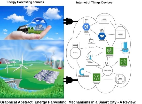
Energy Harvesting Mechanisms in a Smart City—A Review


1
Departamento de Electronica Telecomunicações e Informática, DETI, Universidade de Aveiro, Campus Universitário de Santiago, 3810-193 Aveiro, Portugal
2
Instituto de Telecommunicações, Universidade de Aveiro, 3810-193 Aveiro, Portugal
*
Author to whom correspondence should be addressed.
Smart Cities 2021, 4(2), 476-498; https://doi.org/10.3390/smartcities4020025
Submission received: 16 February 2021
/
Revised: 27 March 2021
/
Accepted: 30 March 2021
/
Published: 8 April 2021
(This article belongs to the Special Issue Cloud-Based IoT Applications for Smart Cities)
Abstract
:The issue of how to power the deployed Internet of Things (IoT) nodes with ubiquitous and long lasting energy in order to ensure uninterruptible optimisation of smart cities is of utmost concern. This among other challenges has continued to gear efforts toward energy harvesting research. With the outbreak of COVID-19 pandemic and the lockdown that nearly paralysed activities of everyday living in many nations of the world, option of human remote interaction to enforce social distancing became imperative. Hence, the world is witnessing a renewed awareness of the importance of IoT devices, as integral components of smart city, especially for the essence of survival in the face of lockdown. Energy harvesting is a possible solution that could enable IoT nodes to scavenge self-sustaining energy from environmental ambient sources. In this paper, we have reviewed most sources within city that energy could be harvested from, as reported by researchers in literature. In addition, we have submitted that energy sources can be application specific, such that, since there are many free sources in the city as presented in this review, energy should be scavenged within close proximity of need for various IoT devices or wireless sensor networks (WSNs), for smart city automation.
1. Introduction
Energy harvesting (EH) is the process by which energy that are rather wasted in the environment are converted into usable sources to power autonomous devices. Energy harvesting proffers solution to the energy challenge of Internet of Things (IoT) networks by enabling the possibility to physically or chemically scavenge ambient energy from the environmental sources either by natural or man-made phenomena [1,2,3,4].
Meanwhile, a smart city is a concept describing the level of urbanization and technological development of any city. The definition of the smartness of a city differs from one city or nation of the world to the other. This concept is usually defined by the day-to-day needs of the people in relating with themselves or with things and the particular application areas of interest of the smart city developers [5]. To one city, smartness might be the need for safety in the time of natural disaster and emergencies such as earthquake, flood, or fire outbreak [6]. To another it is the challenge bothering on security and terrorism [7]. While to yet another, smart city interest may arise from the need to make living generally comfortable to the people [8]. The important features while referring to a smart city among other things are that objects and/or humans are connected to objects or humans through the internet: for example, buildings, cars, and home appliances are connected and relate with each other. In this manner, the information about the smart city is made available to the planners of the city, and there is general automation of the city on challenging issues. These concerns are the application areas such as access to instant health care delivery services, improvement in energy and transportation networks (despite increasing congestion of the city), improvement in human general daily living, safe guarding security intelligence services, instant rescue operations during natural disaster or fire outbreak, generating green energy sources to suppress carbon burning and climate change, among others [1,6,7,8].
In the smart city, there is web technology by which means physical objects are managed and accessed, thereby objects are connected to the internet to make them smart and enabling them to interact as machine-to-machine or human-to-machine [5,6,7,8]. The smart city relies on sensory data from IoT in order for the planner to be able to achieve the desirable specifications relating to the particular needs of the city. This is what the ideology of smart city enabled by IoT is about.
The Internet of Things (IoT) is simply an interconnected network of things or human relating with things via the cloud. The IoT communicates data within physical devices that are connected to the internet in the city, by means of its numerous sensors. Thereby allowing interactions between object to object or human to object via the cloud or internet. This means that IoT usually consists of internet-enabled objects; wired or nonwired, among which are; sensors, Radio-Frequency Identification, (RFID) tags, actuators, telephone mobiles, telemedicine networks, and so on [4]. Data about the smart city is therefore made readily available by the IoT for autonomous planning and decision making about such a city in order to improve day-to-day living and continuous human existence. This is as illustrated in Figure 1.
The IoT concept is no longer a nonrealistic ideology to people of various categories. As an example, from the outbreak of the COVID-19 pandemic and the activities lockdown that followed in almost all nations of the world, it has now become very imperative that the concept of Internet of Things (IoT), be improved upon [9]. The IoT and web technology become one major saving grace that most nations resolve to use, in order to continue living almost normally during this global pandemic [10].
Energy Supply to the IoT is a very important requirement to ensure that connected devices are constantly functioning. Hence, the issue that calls for serious concern in the realisation of smart city and its sustainability is how the IoT nodes and/or connected devices might be powered in order to continue to make uninterruptible data available to the planners of the smart city.
Researchers have at different times made several efforts to carry out studies that focus on the management and maintenance of energy supply to first WSNs and presently to IoT nodes [1,11,12]. Recent international research projects are connected with the application of energy management systems to reduce smart buildings’ energy consumption. The EU parliament at some point in 2002, gave directives on the methods to deploy in order to improve buildings’ energy efficiency. Later, scientists have predicted that smart buildings will have over 500 connected smart devices in 2022 [11]. It is therefore paramount to draw closer attention to the increasing energy needs of Internet of Things devices.
The IoT is a major hub of a smart city and it consist of objects that consume more power than WSNs. Hence, it is important to acknowledge that there is currently a paradigm from concerns for energy supply to just wireless sensor networks (WSNs) to that for IoT devices. Since the IoT has successfully combined mobile network computing and cloud server (web) technology with WSNs, all of which have found usable applications in our everyday living in the modern world.
The aim of this review is to report the sources of ambient energy that are available in a city and the conversion mechanisms that can be adopted. This is for the purpose of harvesting energy to supply IoT devices that are connected within a smart city. This will in return make the IoT ubiquitous and self-sustainable, with long lasting energy sources in order to combat the challenge of battery replacements. This is because replacing worn out batteries is a major difficulty if the IoT devices are deployed to inaccessible or toxic environments. We also stated that this will reduce the cost of maintenance a great deal.
Energy harvesting techniques present many promising advantages and unique features for the current and near future IoT and wireless communications technology in general, particularly with the advent of 5G technology in 2020 and the future 6G or beyond 5G. These advantages that cannot be offered by existing batteries or grid operated communications include: self-sustainable capability, energy that is ubiquitous, reduction of carbon footprint, and no-battery replacement and/or no tethering to electricity grids, and they are easily deployed to toxic and/or hostile and inaccessible environments.
The areas of application of energy harvesting techniques regarding our research are such as relating to the modern world of trending in IoT, which include but not limited to specific areas such as; Internet of Medical Things (IoMT), Internet of Mobile Things (IoMobT), Internet of Remote Things (IoRT) [13], and Internet of Environmental Things (IoEnvT).
The IoT network depends on energy harvesting solution for a prolonged lifetime energy supply which will be required for it to acquire real time data aggregation that will be yielded for smart city automation. In this review, the available ambient sources that energy could be harvested from in any city, as presented by many researchers in literature, are looked into.
The merits of energy harvesting have been reported in literature at different times [1,2]. Our major focus in this review is to emphasise that energy can be harvested from within the close proximity of need for the purpose of IoT applications. Hence, we have reviewed and categorised various methods of energy harvesting that are available by looking at recent studies carried out by different researchers. We have considered issues such as the different transduction mechanisms that were adopted to convert energy and the output power obtainable, with their efficiency in some cases. The physical or chemical phenomena surrounding the methods applied and their figures of merits were the basic tools used for our classification [14,15,16,17,18,19,20,21,22,23,24,25,26,27,28,29,30,31,32,33,34,35,36,37,38,39,40,41,42,43,44,45,46,47,48,49]. At the end we were able to come up with our summary that is presented in Table 1 as the major result of the review carried out. The table indicates the type of harvester model, the output power obtainable, and our sources of information. We later drew a conclusion based on the summary that energy can be harvested directly at the particular close proximity of application, instead of replacing batteries in IoT nodes or harvesting energy from different sources to be stored in batteries. This is possible because ambient energy is available in almost everywhere that there is vibration, sunlight, heat, wind, radio frequency, water, and many other naturally occurring sources.
Therefore, energy harvesting techniques as shown in Figure 2 have been proposed as a revolutionary solution towards making the IoT technology realisable and continuously available. The IoT can depend on energy realised from the EH to function ubiquitously and without interruption.
The remaining aspect of this review is called: State of the Art of Energy Harvesting Schemes in a smart city; this is the aspect where we explained and categorised most of the different methods that scientists and engineers have used to convert energy from natural or man-made phenomena to usable quantity of energy for the purposes of powering sensors and IoT nodes.
This is followed by the section where we summarised our findings into a compact easy-to-read table, indicating the quantity of energies realisable in most cases, and for some, the efficiencies of the transduction system. The sources of information and year of research were indicated. We made our findings with studies from about 10 years ago. Lastly, in this section we have justified the need to embark on application dependent energy harvesting for a smart city.
The final section is the concluding part where we made clarifications and buttress on the need to harvest energy for IoT devices at close proximity of applications.
2. State of the Art (SOA) of Energy Harvesting Schemes in a Smart City
The earlier studies on energy were concerns for batteries attached to the IoT nodes. There were attempts to make the entire network of low cost of maintenance by reducing the physical sizes of the batteries, while improving on their lifespan, and those of the connected devices [50]. This was achieved to some extent by making the connected microprocessors, embedded sensors, and actuators to be miniaturised in order to reduce the energy consumption of individual component of the IoT devices. Then, there were studies on increasing battery-lifespan and their physical-size compactness, while making them more efficient [51]. Other researchers considered that duty cycling and event driven protocols should be introduced. By this, they reasoned that some components will be placed on idle mode when not in use, thereby conserving some energy [12].
However, with all these aforementioned efforts in place, there will still continue to be a level of maintenance cost associated with replacement of batteries and visits to the exact locations of IoT nodes. Then, there will be challenges of how to replace batteries when the IoT devices are deployed to hard-to-reach sites, such as toxic regions of the smart city. Furthermore, it will become more difficult if they are in dangerous sites, when there is need for smart city rescue or emergency applications.
There are several ambient sources that energy can be harvested from in any city, as there are different methods that could be deployed to scavenge energy from these sources. In this review, the most common sources of energy that can be harvested in a city are explained. Some of these are: mechanical vibration sources, solar radiation, radio frequency, thermal, and turbine.
2.1. Mechanical Vibration Energy Harvesting (VEH)
Mechanical ambient vibration energy can be effectively converted to electrical energy for IoT devices, since vibration is available almost everywhere there is human and/or machine activities. Studies show that vibration energy can be generated from: human walking, heel strike of navy boot, external transmitter, bridge vibration, Ac Power lines, handrail of subway or on buses, etc. [2,14,15,16,17,18]. There are several studies, both experimental and practical, reported in literature about Vibration Energy Harvesting (VEH) transduction. The mechanisms of VEH can be categorised into four major methods: electromagnetic, electrostatic, piezoelectric, and turbine [2,14,15,16,17,18,19,20,21,22,23,24,25,26,27,28,29,30,31,32,33,34,35,36]; two or more of these mechanisms were sometimes combined together to enhance performance [2,14].
2.1.1. Electromagnetic Vibration Energy Harvesting
Energy can be derived from ambient vibration in the form of electromagnetic transduction based on the theory of Faraday’s Electromagnetic Induction Law that established that electromotive force (EMF) is generated when a conductor is inserted and moved within a magnetic field. This is as shown in Figure 3. Different scenarios of harvesting energy by electromagnetic-based VEH are presented in literature [2,14,15,16,17].
It was presented in [2] that vibration energy could be harvested based on human walking for applications such as wearable electronics devices. A man weighing 68 kg can generate 67 W through vibration if he walks at 2 steps per seconds and has a heel movement of 5 cm. However, the reality of such applications depends on many factors such as the gait of the EH device, the mechanical and electrical power losses, the electromechanical efficiency, among others. This implies that only a fraction of this energy can be efficiently converted to usable energy. Song-mao CHEN and Jun-hui HU in [14] presented an experimental study on combination of Electromagnetic and Piezoelectric VEH, whereby one hand-wound enamel copper coil and 2 pairs of NdFeB permanent magnet were the set up for electromagnetic induction and the impact-induced vibration module for piezoelectric harvester. It was stated by them that 429.3 µJ and 6547.2 µJ were recorded for the piezoelectric impact-induced vibration component and electromagnetic component respectively. In a similar manner, Alireza Khaligh et al. [2] in their review reported that parasitic energy through heel strike can be harvested from a Navy work boot by installing a lead zirconate titanate (PZT) at the heel of the boot. They submitted that up to 8.4 mW of average power can be generated from up and down movement of the heel using a PZT bimorph structure under a resistive load of 500 kΩ and a frequency of 900 mHz. In addition, vibration from human respiratory effort has been demonstratively scavenged to generate appreciable amount of energy [15,16]. Ehsaneh Shahhaidar et al. [15] in their research established that electromagnetic energy can be harvested through human breathing; this can find suitable application for wearable biosensor as they established that a mean power of 2 mW was attained when they simulated the generator current induced by motions from respiration, through a resistive load of 7 Ω given by the armature resistance, and the estimated voltage of 200 mV was generated, assuming a respiratory rate of 12 breaths/minutes. It was as well reported in [16] that during an exercise that lasted for 5 min, an electromagnetic human respiratory EH was made to produce 6.44 mW and 30.4 mJ of energy.
- Mechanical Energy Conversion for EH Faraday’s Electromagnetic induction law establishes that electromotive can be generated around a conductor when inserted and moved within a magnetic field, as shown in Figure 3. From Faraday’s law of electromagnetic induction, the generated electromotive force, , and, magnetic flux , within the coil loop is given by the relation in (1):The circuit of an electromagnetic energy harvester consists of N turns of coil of wire, moved within the magnetic field produced by a permanent magnet. The total magnetic flux of N turns is given by, . This is defined as sum of magnetic flux for each turn, and is the area enclosed for a wire loop with ith turns.the relation in (2) can be rewritten as shown in Equation (3) as;where, is Transduction factor, corresponding to the magnetic flux gradient.The EMF can be written as follows in (4); which is showing that EM induction can be either of fixed magnetic field with changing area or changing magnetic field with constant area.The possible topologies for this are as shown in Figure 4a,b.
2.1.2. Electrostatic Vibration Energy Harvesting
Electrostatic or capacitive Vibration EH usually refer to the principle of capacitive inductance, such that voltage or capacitance can be varied when a precharged capacitor plate (or electrode) changes distance with another plate. The plates are separated by air, vacuum, or insulating dielectric material and are moved by electrostatic forces. In the setup of Figure 5, electrostatic VEH is presented as a situation where ambient mechanical vibrations can be used to move the plate of the charged capacitor (upper electrode) in order to change distance with respect to the other plate (lower electrode). In most cases where the insulating dielectric material is employed, it is to increase the harvested energy and also to prevent the plates of the capacitor from touching each other under applied load. That is, in principle, electrostatic energy harvesters will usually convert environmental energy to electrical energy when ambient vibration acts against electrostatic force of a variable capacitor to move its plates [18,19,20,21,22,23,24]. This is as reported by Akin-Ponnle A.E. et al. [18], when they presented that an electrostatic micropower generator, using cantilever-electret arrangement as the electrodes, was vertically vibrated to scavenge ambient energy. The maximum amount of power realised from experiment by this arrangement was 48 nW.
Using ferrofluid droplet rotated on a hydrophilic surface to generate a fully liquid-based electrostatic energy was demonstrated by Dongil Kim et al. [19]. In their study, the ferrofluid which was a conducting liquid serves as the layers of movable dielectric; this was rotated by a magnetic field of a top and bottom conducting electrode plates, leading to variation in capacitance to generate electric power. Furthermore, 19.3 µW was recorded as an average output power generated with 8 ferrofluid droplets at 180 r/min rotational speed. In [20], Researchers designed an energy harvester based on electrostatic transduction using an ultrasonic wave from a transmitter as a means of mechanical excitation to produce electrical energy in any direction, from a central mass of silicon-insulator MEMS. Their experimental results show that electrical power of 24.7 nW, 19.8 nW, and 14.5 nW were generated in x, y, and z directions of the device for 15 s. Researchers in [23] show an improvement on the use of electret-based electrostatic energy harvester by generating an output power of 109.71 W/cm of unit surface area of angular electrode structures incorporated with switching converter circuit 9.6 μW of maximum power was reported to be scavenged from this arrangement.
- Energy Conversion of Electrostatic EHThe electrostatic mechanism is shown in Figure 5. This is working based on capacitive inductance phenomenon. Here, voltage or capacitance can be varied when a precharged capacitor plate (or electrode), changes distance with another plate. The plates are separated by air, vacuum, or insulating dielectric material and are moved by electrostatic forces originating from ambient vibration.In a vibration based electrostatic energy harvester, there are two electrodes, upper and lower, separated by dielectric material, air, or vacuum, as shown in Figure 6. In the situation where an electret which is a quasipermanent dielectric is used as the insulating material between the upper and lower electrodes [18], it will induce counter charge on the surfaces of the upper and lower electrodes. The total amount of charge induced this way is kept constant as long as the amount of charge on the dielectric remains constant. The amount of counter charge on each electrode depends on the separation distance between the two plates. Hence, electrical energy is generated when vibration changes the distance between the electrodes. Capacitive inductance law states the relation between the quantity of charge and induced voltage, in a way that,where, Q is in Equation (5), is the quantity of charge on the plates, C is the capacitance, and V is the voltage induced.It is possible to write that,Thus, two possibilities are usually considered for electrostatic energy conversion: voltage constrain and charge constrain.In both cases, the total energy, E, converted from mechanical vibration to electrical is given as
2.1.3. Piezoelectric Vibration Energy Harvesting
The Piezoelectric transduction mechanism of vibration energy harvesting have been widely studied and reported in literature [2,3,26,27,28,29,30,31,32,33,34,35,36]. Piezoelectric VEH is argued to have the advantages of maximum realisable power density, being easily implementable, and that it is easily fabricated since the external components required are not usually large [2]; this is against its electromagnetic and electrostatic transduction counterparts. In most cases piezoelectric VEH has been combined with either of the two other transduction mechanisms for optimum power generation [2,3,25]. The piezoelectric VEH is born out of the phenomenon that certain crystalline materials will become electrically polarised when they are subjected to mechanical force or pressure, which is referred to as “piezo”. Hence the word “piezoelectric” is coined out of two words, “piezo” (or pressure) and “electricity”. As described in Figure 6, piezoelectricity is based on the principle of electromechanical behaviour of crystalline materials such that they are electrically polarised when subjected to mechanical force (stress) and also on the converse, they experience mechanical strain when they are exposed to electric field [2]. Therefore, piezoelectricity can be of either impact [29,30,31,32,33,34,35,36] or resonant [30] type. A typical piezoelectric energy harvester will have a cantilever beam that has a patch of piezoelectric attached to the surface of the beam. Hence depending on the method adopted, the piezoelectric will either generate electric charged when it is compressed or pulled (i.e., impact type of piezoelectric energy harvester—PEH) or will cause the material to expand or compress when electric voltage is applied to it (i.e., resonant type of PEH).
Vibration Energy using piezoelectric transduction is reported in literature to be from different interesting sources such as human footwear, AC power line, machine vibration, bridge vibration, motor vibration, etc. [26,27,28,29,30]. Alireza Abasian et al. [26] reported a design to optimise magnetic field EH in order to power devices needed to monitor an ac power line to constitute a smart grid. The arrangement was made of cantilever beam with a miniaturised permanent magnet attached to the tip and made to vibrate as a result of the magnetic field produced by the ac power line. A piezoelectric beam installed in the vicinity of the ac power line was experimentally verified for this method of generating energy. J. G. Rocha et al. [27] demonstrated how piezoelectric energy can be harvested from vibration from human walking when they fabricated an energy harvesting shoe incorporated with piezoelectric polymer in the sole, in order to scavenge energy from human walking vibration while wearing the shoe. Another group of researchers in [31] in their study reported that up to 5.5 mW of output power with resistance of 500 Kohms corresponding to 9.2 mW/cm was produced by their proposed “multi-directional compressive-mode piezoelectric energy harvester (MC-PEH)”. This design is reported to have the capability of harvesting energy from vibration at any angle in a plane, unlike previous ones which usually harvest energy from only fixed vertical (resonance) direction to the surface of cantilever beam. In addition, turbulence or laminar from air or water stream could be used as external vibration source for piezoelectric energy harvester. This is as presented by Xiaotong Gao et al. [32] in their development of “piezoelectric flow energy harvester”, whereby they designed a piezoelectric cantilever to vibrate and generate energy as a result of the vibration of a cylindrical object that the cantilever is attached to as an extension, when subjected to wind or stream flow. These researchers from Philadelphia, demonstrated that an MCP9700 thermometer (Microchip Inc., Chandler, AZ, USA) was continuously powered by their designed using a fan rotating at 5.2 m/s to generate wind. In addition, it was reported that turbulent excitation mechanism was more dominant than laminar flow. Furthermore, recent studies show that piezoelectric vibration energy could also be scavenged from passengers while using the handrails of subway or on the bus. This is explained by Zhenjing Li et al. [33] in their research and fabrication of dual-mode PEH. This design has 2 forms of excitation: energy from vibration as a result of passengers’ activities and also excitation due to the pulling force of the handrail. The experimental results yielded output power of 150 µW and 15 mW from vibration excitation and random pulling of the handrail, respectively. Yet another group of researchers [34], in their study explain how the rotating effect of gear teeth was used to pluck an AFM- like piezo-electric cantilever, and this will in return be driven by another oscillating mass. The output power and voltage realisable by this method of harvesting were said to have reached a usable level of practical applications, though there was no actual value reported by the authors. Increasing the number of cantilevers in a single gear will also lead to better performance. Other studies in literature presented how to improve on the performance of one model or the other, for all the types of vibration energy discussed. This is of interest with the report of researchers in [35], where they submitted that the proposed T-shape piezoelectric harvester will outperform other existing structure of the same model, and that the power density will be 4.8 times higher than others as a result of adopting a T-shaped geometry cantilever for their harvester. In addition, Xiaotian Li et al. [36] reported that up to an output power of 14.6 mW is realisable in their developed flex-compressive mode piezoelectric harvester, with output voltage of 110 Vpp, under a load of 40 KΩ. This they reported to be possible from their piezoelectric vibration energy harvester of 2 ring-type stacks of piezo, bow-shaped elastic plates, and one shaft that precompresses the plates and the piezoelectric stacks, hence they were able to generate high electric voltage using piezoelectric transduction effect as a result of this arrangement. Many findings have been carried out about vibration energy harvesting transduction techniques; it is however observed that piezoelectric energy harvesting technique is widely being pursued as a result of usual availability of piezoelectric materials of satisfying performances and the ability of the transducer to generate better power densities [37,38,39].
- Energy Conversion of Piezoelectric EHThe piezoelectric VEH is born out of the phenomenon that certain crystalline materials will become electrically polarised when they are subjected to mechanical force or pressure, which is referred to as “piezo”. Hence the word “piezoelectric” is coined out of two words: “piezo” (or pressure) and “electricity”. This is as shown in Figure 6.Piezoelectricity is based on the principle of electromechanical behaviour of crystalline materials such that they are electrically polarised when subjected to mechanical force (stress) and also on the converse, they experience mechanical strain when they are exposed to electric field [2]. Therefore, piezoelectricity can be of either impact [26,27,28,29] or resonant [30] type. This particular class of crystalline materials known as ferroelectric, such as lead zirconate titanate (PZT), are usually used for piezoelectric energy harvesting. Some other examples of materials for piezoelectric are barium titanate, Gallium nitride, and amazonite quarts, such as those from dry bone and sugar cane.A typical piezoelectric energy harvester will have a cantilever beam that has a patch of piezoelectric attached to the surface of the beam. Hence depending on the method adopted, the piezoelectric will either generate electric charge when it is compressed or pulled (i.e., impact type of PEH) or will cause the material to expand or compress when electric voltage is applied to it (i.e., resonant type of PEH). A structure of PEH is as shown in Figure 7.Usually, full-bridge rectification circuitry is commonly used for energy harvesting. This was applied in [3] to obtained a DC voltage, as shown in Figure 8. Here, the signal generator produces sine wave signal, which is amplified and acts as control signal for the sinusoidal excitation produced by the vibration exciter. The frequency and amplitude of the excitation signal are adjustable.voltage produced by the PEH in this way could be detected by oscilloscope, and load voltage after bridge rectification is measured by the voltmeter.
Consider the relation in Equation (8), describing the stress distribution along the length of a typical cantilever beam with respect to the excitation frequency.
This is depicting the piezoelectric phenomena that electric energy is generated when the piezo component is compressed, and the converse also is true to compress the piezo when voltage is applied.
Here, is the strain component, is the induced stress, D is the displacement, is the electric field component, is indicating elasticity evaluated at constant electric field, and is the electric field evaluated at constant stress, d and , are the piezoelectric coefficient and its transpose respectively.
2.1.4. Turbine Energy Harvesting
Turbines are devices that convert kinetic energy of wind or water into rotational motion. Turbine Energy Harvesters usually convert energy from the wind or ocean to usable energy [17,40,41]. They are mostly not stand-alone harvesters, as they always require the aid of some other means of energy transduction mechanisms; which are usually that of Vibration Harvesters, in order to efficiently convert the energy from the wind or water to usable output [17].
Turbine energy harvester can be of wind or water type [17,41]. The methods reported in literature are turbine with the use of piezoelectric material, electromagnetic generator, and acoustic resonators [17,41,42].
Wind energy as shown in Figure 9 could be used to propel another form of Vibration Energy Harvesters, such as Electromagnetic VEH and Piezoelectric VEH [17,26].
Wind energy harnessing is usually based on the dynamic phenomena of the wind turbulence such as vortex induced vibration, rain vibration, divergent oscillation, wake galloping, etc., as well as static activities known as overturning, static deformation, sliding, and static instability. This is as researched by Hyung-Jo Jung et al. [17], who in their research adopted wake galloping phenomenon of vibrating a bluff body under wind load, after arguing that its range of wind speed is wide with finite, though large amplitude.
This is considered to be against the aerodynamic instability phenomena like vortex induced vibration and flutter. In this scenario, the wake galloping is achieved by wake interference in-between 2 circular cylinders and a permanent magnet to work as linear rotor in solenoid coil on the end of the cylinder that is vibrating in order to generate electricity. They used 3 solenoid coils to carry out tests and characterise induced voltage, vibration, and power generated; they also obtained that under wind speed of between 1.8 m/s and 5.6 m/s, average power of 0.3 W to 1.13 W was generated.
In the same manner, water turbulence as a form of energy can be converted to electrical energy to power IoT devices and underwater sensors. This was demonstrated in [41,42]. The major conversion mechanism used in literature to accomplish water turbine energy harvesting are VEH techniques such as piezoelectric or electromagnetic. The ocean density, its area spanning, and the speed of flow are major determinants of the amount of power realisable [42].
2.2. Solar Energy Harvesting (SEH)
Solar harvester systems extract and convert solar energy into electrical form by using Photovoltaic (PV) cells. The harvested electrical energy can then be in return used to charge IoT nodes. The solar panel converts light energy directly into d.c. electrical energy either in outdoor or indoor conditions. However, the available energy in outdoor environmental conditions is very different from that found in indoor enclosed environments like offices, schools, hospitals, factories, etc.
2.2.1. Indoor Solar Energy Harvesting
The indoor solar energy sources are commonly generated by some artificial means [43], as shown in Figure 10a. Radiation from indoor solar energy has been generally harvested to generate energy for various applications relating to low power consumption devices, and such research activities have been widely studied and reported in literature.
The ambient solar energy sources in the indoor environment which are usually simulated artificially are very weak, hence there is need for booster circuit to harvest the low indoor ambient energy. This as reported in [44], where they realised an output voltage of 3.3 V and almost 95% conversion efficiency was reported, when they designed their harvester with a booster of between 0.65 V to 3 V operating voltage, under an illumination of 2.9 mW/cm. In like manner, a conversion efficiency of 91.23% was reported by X.Meng et al. [45], when they designed a Solar Indoor Energy Harvester with single input dual output converter using 0.18 μm CMOS.
Therefore, the amount of energy harvested indoor is dependent on the indoor illumination conditions such as intensity and spectral of light, incident angle, size and sensitivity of the light source, temperature, and type of solar cells used.
2.2.2. Outdoor Solar Energy Harvesting
The illumination efficiency in outdoor environment that is exposed to direct sunlight is usually very high; this makes photovoltaic (PV) an effective energy harvesting scheme to power IoT nodes. An outdoor illumination, as shown in Figure 10b, can be up to 500 W/m, and amorphous silicon or crystalline cells can yield up to an efficiency of between 15 to 25% [1]. In order to control how to charge the connected battery in the outdoor solar energy harvesting condition, there is a need for a maximum power point tracking (MPPT) device as shown in Figure 11. This will also help in maximising the PV efficiency since the outdoor solar illumination is not the same all through the day.
The use of MPPT was demonstrated in [47], where between 475 mW to 500 mW of average power was harvested in their design of wearable energy harvesting jacket. Photovoltaic (PV) effect is an example of chemical phenomenon that is adopted in energy harvesting schemes. This works based on the fact that when sunlight is focused on some semiconductor materials, solar energy—which will be converted to DC power as a result of PV effect—is generated. PV effect of EH technique is considered to be effective because of its high efficiency and power density [1]. Photovoltaic (PV) solar cells are composed of silicon, which is a device with semiconductor electrical junction. When these particles of silicon absorb sufficient energy from sunlight as a result of direct exposure, the electrons get excited from the holes and migrate towards the load, with an input-output regulator used, in order to generate solar energy [37].
Meanwhile, there are other methods of harvesting solar energy that scientists have reported in literature. For instance, solar roads are becoming famous. An example of a solar road was demonstrated in [46] as infrastructure for transportation and at the same time harvesting energy.
2.2.3. Solar Energy Conversion for EH
The I-V characteristics of the model presented in Figure 12 were used in [43] for a 4-parameter model using a single diode, with the output power of the set-up given as:
where,
where, is the shunt resistance; which is assumed to be infinite, is the light generated current of the diode in amperes, is taken to be the reverse saturation current. is the resistance in series of the photovoltaic module, while, is the thermal voltage of the PV module which is dependent on the absolute temperature, (given as ). Here, is absolute temperature in kelvin. The Boltzmann’s constant k, is usually 1.3807 × 10⁻²³. In addition, the electron charge, q, is .
2.3. Thermal Energy Harvesting (TEH)
Reports of ambient heat energy as sources of dependable supply to low energy consumption devices are very popular in literature in recent times. Thermal Energy Harvesting (TEH) systems are made of thermoelectric generators (TEG) open to higher temperature on a face and lower temperature on the other, resulting in temperature gradient () with an attached load, giving rise to electrical energy generation. This is based on the principle of Seebeck effect [48].
A basic TEH comprises of TEGs, Power Management Module (PMM), and Load/Energy Storage Unit.
A TEG is generally an array of series-connected semiconductor thermocouples clamped in-between two heat conducting ceramic plates that are electrically insulated. Due to the Seebeck effect, when there is a temperature difference across a TEG, each thermocouple composing of p-type and n-type semiconductor material will generate electric energy, and the thermocouple series output power of a TEG will be in the order of microwatts/K. The difference in temperature of the TEG open circuit voltage is proportional to the difference in temperature [49]. This temperature difference is an indication of output energy of the system of the TEH [48]. Electromotive force is produced in a circuit when 2 different metals that are joined together are at different temperature at each junction, as shown in Figure 13. Basically the TEG has 2 thermoelectric semiconductors n and p types which are connected in series electrically with a temperature difference, . As a result of temperature difference, electrons and holes will accumulate on the cold region, making the voltage of the n-p semiconductor to add up, and this can be used to connect an electrical load which in return results in electrical energy generation. The materials that are commonly used for TEH are: Bismuth (Bi), Selenium (Se), Tellurium (Te), and Antimony (Sb).
An example of electrical schematic of a typical TEH is as used by G. Verma et al. in [48], such that, as the environmental temperature changes, the temperature sensor senses the temperature difference in form of heat flow and provides the output in terms of voltage. The polarity of the output voltage change, which is the output of the TEG, is managed using a bridge rectifier. The output voltage of the TEG is fed to Power Management Module (PMM), which in return harvests maximum power from the TEH system and stores the harvested energy by charging the battery which can be source of supply to IoT or WSNs. An output energy of 10.23 J/g was reported, and the ultralow-power microcontroller is used to control all the activities taking place in order to manage the harvester system. To improve the efficiency of thermal energy harvesting, there is a need for proper consideration of such factors as: TE material property selection, schematics of the TEH system used, and optimisation of parameters such as: thermal conductivity, Seebeck coefficient, temperature range, heat transfer, and internal and load resistances.
Energy Conversion of Thermal EH
The figures of merits used to describe the Seebeck effect in [48] are as shown in Figure 14.
where, , in Equation (11), is the Seebeck coefficient.
The difference in temperature, between hot and cold sides is of utmost importance in this phenomenon. This is shown in Equation (12) as given by:
where is the open circuit voltage.
The output power of the TEG is theoretically given as in Equation (13):
Hence, in Equation (14),
this implies that the theoretical Power is proportional to the square of the temperature difference.
2.4. Radio Frequency Energy Harvesting (RFEH)
Recently, the bulk of Energy Harvesting schemes in the city have been developed from Radio Frequency (RF) Energy Harvesting mechanism. This is because efforts have been geared towards scavenging ambient energy resulting from the fall-outs of electromagnetic energy as a result of radio frequency propagation and telecommunication activities. Many studies on RFEH schemes are reported in literature. The RF energy is realisable due to the principle of magnetic induction coupling effect, which allows a time varying current loop to induce another loop of an existing open circuit voltage of the receive loop. The amplitude of loop current, the measure of value and distance between the two loops, and distance between turns of loop, are major determinants of the open voltage and flux received [1]. The receive loop voltage can be stored, and it is also sufficient to power IoT device such as passive RFID.
RFEH is performed by means of antennas able to receive Electromagnetic (EM) energy from the environment that is opened to existing services with ambient RF energy sources such as; Wi-Fi access points, TV and radio stations, cellular base stations, etc. EM energy sources can be categorised as near-field and far-field.
2.4.1. Near Field RFEH
In near-field applications, EM induction and magnetic resonance are usually explored to generate electric power in order to recharge devices within a distance of a wavelength. An instance of near-field RFEH is described in [52], where an unintentional RF energy in the railway environment from 10 kHz to 1 GHz (wideband) was scavenged and converted to usable energy. Up to 84% of the energy was delivered using a metamaterial with a wideband frquency of 350 MHz and a load of 8.5 Kohmns.
2.4.2. Far Field RFEH
In situations involving RFEH far field, up to a few kilometres of EM energy, that usually appear in the form of RF signals, can be received by antennas and converted to power by rectifier circuits [53]. The far field RFEH can be classified further as ambient far-field RFEH and Dedicated far-field RFEH.
- Ambient far-field RFEHThis typically covers transmission frequency in the range of 0.2–2.4 GHz. This scenario is reported in the survey of Action Nechibvute et al. [54], where an output of 1.8 milliwatt was reportedly scavenged from a distance of 77.8 m, for Portuguese DTV station operating at 165 MHz.
- Dedicated Far Field RFEHThis mechanism is concerned with such applications where the particular locations of RF energy are not known, and so there will be a need for the harvester to be switched to directions that are rich in ambient RF signals in order to enhance the performance of RF energy harvesters [45]. An RFEH designed for 900 MHz, which has an efficiency of 36% at a load of 70 ohmns was reported in [1]. Hence, dedicated RF energy sources are usually on-demand supply and generally have high power density due to directional transmission, and it is used to power wireless nodes that require predictable and high amount of energy.RFEH mechanism makes use of rectenna as the basic unit. Rectenna simply put is a combination of a receiving antenna and a rectifying circuit. Rectennas for RF Energy are usually meant to collect radiation energy from RF signals and rectify into DC usable energy components and then condition it to supply an external load. A conventional RF energy harvesting systems is as shown in Figure 15. An impedance matching circuit is needed to effectively manage the RF energy received by the antenna. A rectenna for this purpose must accommodate various types of scaling related to antenna gain, radiation pattern, array size, harvested power, frequency, and dc load [52].
2.4.3. Energy Conversion of RFEH
The figures of merit of RFEH are mostly examined based on that of the electric field distribution by considering the transfer coefficient of the rectenna involved and the harvesting efficiency [55]. The electrical equivalent circuit of RFEH is as shown in Figure 16.
The resonant frequency of the material of the metasurface is given by Equation (15),
where, L and C are the effective inductance and capacitance of the material respectively [52].
The efficiency of the RF Harvester is given by Equation (16),
where is the total time-average power harvested by resistive load, and is the total time-average power incident on metasurface used for collecting the EM energy. Another important figure of merit is the absorption efficiency, relating to the reflection and transmission coefficients respectively [52].
2.5. Acoustic Energy Harvesting (AEH)
Research into energy harvesting from pressure waves as a result of vibration source popularly known as Acoustic Energy Harvesting is becoming an interesting subject being reported in literature. A noise usually arises from irregular sound, and a combination of irregular sound source over a time period will amount to acoustic power [41]. This type of energy is common in everyday life activities at: factories, construction sites, etc., and it is believed to be clean source of energy that can be able to power IoT nodes [54,55,56,57]. However, it is important to note that this form of EH scheme works like the vibration energy harvesting schemes, and so it can be combined with one or more of the VEH techniques as discussed in literature [56,57], to achieve optimum value of output energy. An output energy of 26.89 μW was reported by P. Mayer et al. [41], in their design of self-powered acoustic sensor, which was combined with microbial fuel cells for underwater monitoring.
3. Summary of SOA of EH Mechanisms in a Smart City
In this review, we have submitted that energy harvesting schemes are possible solution to energy challenges of IoT devices in a smart city. The concerns for low cost of maintenance of IoT nodes, long-lasting lifespan of batteries, hard to reach sites of deployed IoT nodes, among others, are addressed. These concerns have continued to drive more research interest on energy harvesting for IoT devices and WSNs in a smart city, as a result of its numerous benefits.
Energy harvesting has a particular merit of proffering solution to Internet of Things devices, especially when they are deployed to inaccessible sites.
The major findings of this review are presented in Table 1, where we have classified most mechanisms of EH from available ambient sources within the city as Mechanical Vibration harvesters, Solar harvesters, Thermal harvesters, Radio frequency harvesters, Turbine harvesters, and Acoustic harvesters.
The maximum output energy generated and/or efficiencies as the case may be, as presented by different researchers in literature, is tabulated in Table 1.
4. Discussion
In this review, we have looked at different sources that energy could be harvested from in a city as presented by different researchers in literature. In our review, EH schemes are grouped into different categories, depending on the type of mechanism that is adopted. First, we explained energy harvesting from mechanical vibration sources, which usually convert ambient kinetic energy to electrical form. Such harvesting mechanisms are: electromagnetic, electrostatic, and piezoelectric [15,16,17,18,19,20,21,22,23,24,25,26,27,28,29,30,31,32,33,34,35,36]. In addition, there are other hybrid mechanisms that are classified as Vibration Energy Harvesting. They usually adopt mechanical mode of vibration to convert kinetic energy to usable form of energy that can be used to power IoT devices. An example of these types of hybrid harvesters include the turbine harvesters. Usually, turbine harvesters—either wind or water type—will need to combine a type of other forms of vibration energy harvesters before they can convert mechanical vibration energy to electrical energy usable by the IoT devices for smart cities. The common types of these are turbine harvester with electromagnetic VEH or turbine harvester with electrostatic VEH [32]. We also cited an example of turbine with acoustic in this review [42]. Hence Turbine energy harvesters are not stand-alone harvesters. The maximum energy realisable for the different scenarios can be looked up in Table 1.
Next, we discussed Solar Energy Harvesters both for indoor and outdoor harvesting using Photovoltaic cells. This type of harvester makes use of transduction mechanisms that convert energy from the sunlight to electrical energy using PV effect. Energy of the sun is at its best during the day for Outdoor Solar Energy Harvesting. Artificial illumination is usually simulated in the case of Indoor Solar Energy Harvesting, as discussed in Section 2.2 of this paper.
Thermal Energy Harvester is another important mechanism discussed in this review. This method of EH uses the principle of Seebeck to convert heat energy to electrical energy. There are occasions where there could be a hybrid of solar with thermal harvester. This type of mechanical harvester can be used to power smart buses, ambulances, or other IoT devices, if maximum power is sufficiently harvested from the TEG, when the PMM is properly implemented. This scheme is explained in Section 2.3.
Another viable means of harvesting ambient energy in a city is RF energy harvesting. This is highlighted under three different schemes in this paper as: near field RFEH, Ambient Far Field RFEH, and Dedicated Far Field RFEH. These mechanisms generally convert ambient energy from the fall outs of electromagnetic energy resulting from radio frequency propagation and telecommunication activities. RFEH can be a very useful source of energy supply to IoT devices, because of its high output power reported in literature. An amount of energy as high as 1.8 MW is realisable through this mechanism as reported in [54] and presented in Table 1.
Lastly, the use of acoustic energy harvesters for converting sound energy to usable source for powering IoT devices was discussed in Section 2.5. However, this is not a stand-alone EH scheme, like the turbine harvesters, AEH usually needs to combine one or more form of VEH, to achieve optimum output energy.
All the above mechanisms of energy harvesting have been highlighted in this review, with their methods of energy conversion, in terms of the physical or man-made phenomena that were adopted, coupled with the figures of merits considered in each cases.
As a result of the foregoing, situations whereby each IoT node or network is made to generate its own energy, based on the sources that is best available to it, can be attained. These energy harvesting schemes are meant to either be embedded or integrated with such IoT devices, thereby providing situations of application dependent energy harvesting.
As an instance, an RFEH mechanism that is generated from rail system tracking can be used, if the IoT is to service the smart city in close proximity to train station. In this review, we have cited an example of how train movement is used to vibrate metamaterial around the rail tracking, in order to harvest energy. An amount of energy corresponding to between 10 kHz to 1 GHz was said to be realisable by this mechanism [52].
Some researchers suggested dimming of lights, while pondering how to conserve energy supply to street lighting as an example of macro IoT [55,58]. Here, making energy harvesting scheme such as solar pavements,. [59], to power the installed halogen lamps on the street, can be a long lasting solution. This is thanks to the storage facilities that are easily obtainable to store up energy during the day when the energy of the sun is at its peak.
Moreover, smart buses can be used as ambulances in the face of emergencies for prompt responses to smart health delivery. These buses can be built to rely on self-generated hybrid energy harvested from solar and thermal schemes. This will greatly overcome the timeliness requirements, traffic protocols, and routing mechanisms challenges for conserving energy in the situations when the ambulances will have to draw energy from a smart grid [12,60].
In addition, there will be reduction in cost of maintenance of IoT nodes and the smart city in general. Having been saved from undue procurement of energy storage facilities, replacement of batteries, and energy losses due to termination to the grid, all these benefits will be as a result of harvesting energy in close proximity of IoT nodes.
5. Conclusions
There are so many sources of ambient energy in human environment that could be explored to generate sustainable energy to enhance the promising fields of Internet of Things and WSNs, especially the devices of IoT for smart city actualisation. The common sources of energy that could be harvested are presented in this paper.
Energy can be harvested directly at the particular close proximity of application because ambient energy is available in almost every place that there is vibration, sunlight, heat, wind, radio frequency, water, and many other naturally occurring sources. This will ensure optimum benefits of EH schemes in the smart city, such as low cost of maintenance, prompt responses to various demands from different sections of the city, among others. Energy harvesting techniques have been proposed as a revolutionary solution towards green communications. Energy harvesting capabilities facilitate the implementation of smart cities through the ubiquitous interconnectivity of Internet of things devices, as long lasting energy sources. The phenomena that relate to the facts and happenings with principles leading to major techniques of energy harvesting are highlighted and reviewed in this paper.
Funding
This work is funded by FCT/MCTES through national funds and cofunded by EU funds under the project UIDB/50008/2020-UIDP/50008/2020.
Institutional Review Board Statement
Not applicable.
Informed Consent Statement
Not applicable.
Data Availability Statement
Not applicable.
Acknowledgments
Tertiary Education Trust Fund, TETFUND, Nigeria. The Federal Polytechnic, Ile-Oluji, Nigeria.
Conflicts of Interest
The authors declare no conflict of interest.
Abbreviations
The following abbreviations are used in this paper:
| IoT | Internet of Things |
| EH | Energy Harvesting |
| WSNs | Wireless Sensor Networks |
| RFID | Radio-frequency Identification |
| 5G | Fifth Generation |
| 6G | Sixth Generation |
| IoMT | Internet of Medical Things |
| IoMobT | Internet of Mobile Things |
| IoRT | Internet of Remote Things |
| IoEnvT | Internet of Environmental Things |
| VEH | Vibration Energy Harvesting |
| EM | Electromagnetic |
| MEMS | Micro Electromechanical Systems |
| PEH | Piezoelectric Energy Harvesting |
| MC-PEH | Multidirectional Compresive-mode PEH |
| PV | Photovoltaic |
| SEH | Solar Energy Harvesting |
| MPPT | Maximum Power Point Tracking |
| DC | Direct Current |
| TEH | Thermal Energy Harvesting |
| TEG | Thermo-Electric Generator |
| PMM | Power Management Module |
| RFEH | Radio Frequency Energy Harvesting |
| RF | Radio Frequency |
| DTV | Digital Television |
| AEH | Acoustic Energy Harvesting |
| SOA | State of the Art |
References
- Shirvanimoghaddam, M.; Shirvanimoghaddam, K.; Abolhasani, M.M.; Farhangi, M.; Barsari, V.Z.; Liu, H.; Dohler, M.; Naebe, M. Towards a Green and Self-Powered Internet of Things Using Piezoelectric Energy Harvesting. IEEE Access 2019, 7, 94533–94556. [Google Scholar] [CrossRef]
- Khaligh, A.; Zeng, P.; Zheng, C. Kinetic Energy Harvesting using Piezoelectric and Electromagnetic Technologies- State of the Art. IEEE Trans. Ind. Electron. 2010, 57, 850–860. [Google Scholar] [CrossRef]
- Sang, Y.; Huang, X.; Liu, H.; Jin, P. A Vibration-Based Hybrid Energy Harvester for Wireless Sensor Systems. IEEE Trans. Magn. 2012, 48, 4495–4498. [Google Scholar] [CrossRef]
- Huang, J.; Meng, Y.; Gong, X.; Liu, Y.; Duan, Q. A Novel Deployment Scheme for Green Internet of Things. IEEE Internet Things J. 2014, 1, 196–205. [Google Scholar] [CrossRef]
- Desdemoustier, J.; Crutzen, N.; Giffinger, R. Municipalities’ understanding of the Smart City concept: An exploratory analysis in Belgium. Technol. Forecast. Soc. Chang. 2019, 142, 129–141. [Google Scholar] [CrossRef]
- Mohammad, N.; Muhammad, S.; Bashar, A.; Khan, M.A. Formal Analysis of Human-Assisted Smart City Emergency Services. IEEE Access 2019, 7, 60376–60388. [Google Scholar] [CrossRef]
- Laufs, J.; Borrion, H.; Bradford, B. Security and the Smart City: A Systematic Review. Sustain. Cities Soc. 2020, 55, 102023. [Google Scholar] [CrossRef]
- Angelidou, M.; Psaltoglou, A.; Komninos, N.; Kakderi, C.; Tsarchopoulos, P.; Panori, A. Enhancing Sustainable Urban Development through Smart City Applications. J. Sci. Technol. Policy Manag. 2018. [Google Scholar] [CrossRef]
- Chaudhari, S.N.; Mene, S.P.; Bora, R.M.; Somavanshi, K.N. Role of Internet of Things (IOT) in Pandemic Covid-19 Condition. Int. J. Eng. Res. Appl. 2020, 10, 57–61. [Google Scholar]
- Nguyen, C.T.; Saputra, Y.M.; Huynh, N.V.; Nguyen, N.-T.; Khoa, T.V.; Tuan, B.M.; Nguyen, D.N.; Hoang, D.T.; Vu, T.X.; Dutkiewicz, E.; et al. A Comprehensive Survey of Enabling and Emerging Technologies for Social Distancing—Part I: Fundamentals and Enabling Technologies. IEEE Access 2020, 8, 153479–153507. [Google Scholar] [CrossRef]
- Khajenasiri, I.; Estebsari, A.; Verhelst, M.; Gielen, G. A review on Internet of Things solutions for intelligent energy control in buildings for smart city applications. Energy Procedia 2017, 111, 770–779. [Google Scholar] [CrossRef]
- Golpîra, H.; Bahramara, S. Internet-of-things-based optimal smart city energy management considering shiftable loads and energy storage. J. Clean. Prod. 2020, 264, 121620. [Google Scholar] [CrossRef]
- Ang, K.L.-M.; Seng, J.K.P. Application Specific Internet of Things (ASIoTs):Taxonomy, Applications, Use Case and Future Directions. IEEE Access 2019, 7, 56577–56590. [Google Scholar] [CrossRef]
- Chen, S.-M.; Hu, J.-H. Experimental Study of a Hybrid Vibration Energy Harvesting Mechanism. In Proceedings of the Symposium on Piezoelectricity, Acoustic Waves and Device Applications (SPAWDA), Shenzhen, China, 9–15 September 2011. [Google Scholar]
- Shahhaidar, E.; Boric-Lubecke, O.; Ghorbani, R.; Wolfe, M. Electromagnetic Generator as Respiratory Effort Energy Harvester. In Proceedings of the IEEE Power and Energy Conference at Illinious, Detroit, MI, USA, 24–28 July 2011. [Google Scholar]
- Shahhaidar, E.; Padasdao, B.; Romine, R.; Stickley, C.; Lubecke, O.B. Electromagnetic Respiratory Effort Harvester: Human Testing and Metabolic Cost Analysis. IEEE J. Biomed. Health Inform. 2015, 19, 399–405. [Google Scholar] [CrossRef]
- Jung, H.-J.; Lee, S.-W.; Jang, D.-D. Feasibility Study on a New Energy Harvesting Electromagnetic Device using Aerodynamic Instability. IEEE Trans. Magn. 2009, 45, 4376–4379. [Google Scholar] [CrossRef]
- Akin-Ponnle, A.E.; Ponnle, A.A.; Falaki, S.O. Vertical Vibration based Electret-Cantilever Method of Micro-Power Generation for Energy Harvesting. Int. J. Eng. Innov. Technol. (IJEIT) 2014, 3, 218–223. [Google Scholar]
- Kim, D.; Yu, S.; Kang, B.-G.; Yun, K.-S. Electrostatic Energy Harvester Using Magnetically Actuated Liquid Dielectric Layers. J. Microelectromech. Syst. 2015, 24, 516–518. [Google Scholar] [CrossRef]
- Flower, A.G.; Moheimani, S.O.R.; Behrens, S. An Omnidirectional MEMS Ultrasonic Energy Harvester for Implanted Devices. J. Microelectromech. Syst. 2014, 23, 1454–1462. [Google Scholar]
- Kempitiya, A.; Borca-Tasciuc, D.A.; Hella, M.M. Low-Power ASIC for Microwatt Electrostatic Energy Harvesters. IEEE Trans. Ind. Electron. 2013, 60, 5639–5647. [Google Scholar] [CrossRef]
- Fowler, A.G.; Moheimani, S.O.R.; Behrens, S. Design and Characterization of a 2-DOF MEMS Ultrasonic Energy Harvester with Triangular Electrostatic Electrodes. IEEE Electron Device Lett. 2013, 34, 1421–1423. [Google Scholar] [CrossRef] [Green Version]
- Ahmed, S.; Kakkar, V. An Electret-Based Angular Electrostatic Energy Harvester for Battery-Less Cardiac and Neural Implants. IEEE Access 2017, 19631–19643. [Google Scholar] [CrossRef]
- Torres, E.O.; Rincon-Mora, G.A. A 0.7-µm BiCMOS Electrostatic Energy-Harvesting System IC. IEEE J. Solid State Circuits 2010, 45, 483–496. [Google Scholar] [CrossRef]
- Kwon, D.; Rincón-Mora, G.A.; Torres, E.O. Harvesting Ambient Kinetic Energy with Switched-Inductor Converters. IEEE Trans. Circuits Syst. I Regul. Pap. 2011, 58, 1551–1560. [Google Scholar] [CrossRef] [Green Version]
- Abasian, A.; Tabesh, A.; Nezhad, A.Z.; Rezaei-Hosseinabadi, N. Design Optimization of an Energy Harvesting Platform for Self-Powered Wireless Devices in Monitoring of AC Power Lines. IEEE Trans. Power Electron. 2018, 33, 10308–10316. [Google Scholar] [CrossRef]
- Rocha, J.G.; Gonçalves, L.M.; Rocha, P.F.; Silva, M.P.; Lanceros-Méndez, S. Energy Harvesting from Piezoelectric Materials Fully Integrated in Footwear. IEEE Trans. Ind. Electron. 2010, 57, 813–819. [Google Scholar] [CrossRef]
- Balguvhar, S.; Bhalla, S. Green Energy Harvesting Using Piezoelectric Materials from Bridge Vibrations. In Proceedings of the IEEE 2nd International Conference on Green Energy and Applications, Singapore, 24–26 March 2018. [Google Scholar]
- Kwon, Y.; Lee, J.; Choi, M.; Lee, J. A study on the P.H.A.S (Piezoelectric energy Harvesting based Access control System) using motor vibration. In Proceedings of the IEEE 17th International Conference on Control, Automation and Systems (ICCAS 2017), Ramada Plaza, Jeju, Korea, 18–21 October 2017. [Google Scholar]
- Panthongsy, P.; Isarakorn, D.; Sudhawiyangkul, T.; Nundrakwang, S. Piezoelectric Energy Harvesting from Machine Vibrations for Wireless Sensor System. In Proceedings of the 12th International Conference on Electrical Engineering/Electronics, Computer, Telecommunications and Information Technology (ECTI-CON), Hua Hin, Thailand, 24–27 June 2015. [Google Scholar]
- Yang, Z.; Zu, J. Toward Harvesting Vibration Energy from Multiple Directions by a Nonlinear Compressive-Mode Piezoelectric Transducer. IEEE/ASME Trans. Mechatronics 2016, 21, 1787–1791. [Google Scholar] [CrossRef]
- Gao, X.; Shih, W.-H.; Shih, W.Y. Flow Energy Harvesting Using Piezoelectric Cantilevers with Cylindrical Extension. IEEE Trans. Ind. Electron. 2013, 60, 1116–1118. [Google Scholar] [CrossRef]
- Li, Z.; Xu, Q.; Tam, L.M. Design of a New Piezoelectric Energy Harvesting Handrail with Vibration and Force Excitations. IEEE Access 2019, 7, 151449–151458. [Google Scholar] [CrossRef]
- Janphuang, P.; Lockhart, R.A.; Isarakorn, D.; Henein, S.; Bri, D.; Rooij, N.F. Harvesting Energy from a Rotating Gear Using an AFM-Like MEMS Piezoelectric Frequency Up-Converting Energy Harvester. J. Microelectromech. Syst. 2015, 24, 742–754. [Google Scholar] [CrossRef]
- Nabavi, S.; Zhang, L. T-Shaped Piezoelectric Structure for High-Performance MEMS Vibration Energy Harvesting. J. Microelectromech. Syst. 2019, 28, 1100–1112. [Google Scholar] [CrossRef]
- Li, X.; Guo, M.; Dong, S. A Flex-Compressive-Mode Piezoelectric Transducer for Mechanical Vibration/Strain Energy Harvesting. IEEE Trans. Ultrason. Ferroelectr. Freq. Control 2011, 58, 698–703. [Google Scholar] [PubMed]
- Shaikh, F.K.; Zeadally, S. Energy harvesting in wireless sensor networks: A comprehensive review. Renew. Sustain. Energy Rev. 2016, 55, 1041–1054. [Google Scholar] [CrossRef]
- Vuller, R.J.M.; Schaijk, R.V.; Visser, H.J.; Penders, J.; Hoof, C.V. Energy harvesting for autonomous wireless sensor networks. IEEE Solid State Circuits Mag. 2010, 2, 29–38. [Google Scholar] [CrossRef]
- Prasad, R.V.; Devasenapathy, S.; Rao, V.S.; Vazifehdan, J. Reincarnation in the ambiance: Devices and networks with energy harvesting. IEEE Commun. Surv. Tutor. 2014, 16, 195–213. [Google Scholar] [CrossRef] [Green Version]
- Rezaei, H.F.; Kruger, A.; Just, C. An Energy Harvesting Scheme for Underwater Sensor Applications. In Proceedings of the International Conference on Electro/Information Technology, Chicago, IL, USA, 31 July–1 August 2012. [Google Scholar]
- Mayer, P.; Magno, M.; Benini, L. Self-Sustaining Acoustic Sensor with Programmable Pattern Recognition for Underwater Monitoring. IEEE Trans. Instrum. Meas. 2019, 68, 2346–2355. [Google Scholar] [CrossRef]
- Erdem, H.E.; Yildiz, H.U.; Gungor, V.C. On the Lifetime of Compressive Sensing Based Energy Harvesting in Underwater Sensor Networks. IEEE Sensors J. 2019, 19, 4680–4687. [Google Scholar] [CrossRef]
- Tan, Y.K.; Panda, S.K. Energy Harvesting from Hybrid Indoor Ambient Light and Thermal Energy Sources for Enhanced Performance of Wireless Sensor Nodes. IEEE Trans. Ind. Electron. 2011, 58, 4424–4435. [Google Scholar] [CrossRef]
- Tran, T.V.; Chung, W.-Y. High-Efficient Energy Harvester with Flexible Solar Panel for a Wearable Sensor Device. IEEE Sens. J. 2016, 16, 9021–9028. [Google Scholar] [CrossRef]
- Meng, X.; Li, X.; Tsui, C.-Y.; Ki, W.-H. An Indoor Solar Energy Harvesting System using Dual Mode SIDO Converter with Fully Digital Time-Based MPPT. In Proceedings of the IEEE International Symposium on Circuits and Systems (ISCAS), Montreal, QC, Canada, 22–25 May 2016; pp. 2354–2357. [Google Scholar]
- Vizzari, D.; Chailleux, E.; Lavaud, S.; Gennesseaux, E.; Bouron, S. Fraction Factorial Design of a Novel Semi-Transparent Layer for Applications on Solar Roads. Infrastructures 2020, 5, 5. [Google Scholar] [CrossRef] [Green Version]
- Brogan, Q.; O’Connor, T.; Ha, D.S. Solar and Thermal Energy Harvesting with a Wearable Jacket. In Proceedings of the IEEE International Symposium on Circuits and Systems (ISCAS), Melbourne, Australia, 1–5 June 2014; pp. 1412–1415. [Google Scholar]
- Verma, G.; Sharma, V. A Novel Thermoelectric Energy Harvester for Wireless Sensor Network Application. IEEE Trans. Ind. Electron. 2019, 66, 3530–3538. [Google Scholar]
- Hou, L.; Tan, S.; Zhang, Z.; Bergmann, N.W. Thermal Energy Harvesting WSNs Node for Temperature Monitoring in IIoT. IEEE Access 2018, 6, 35243–35249. [Google Scholar] [CrossRef]
- Carter, R.; Cruden, A.; Hall, P.J. Optimizing for efficiency or battery life in a battery/supercapacitor electric vehicle. IEEE Trans. Veh. Technol. 2012, 61, 1526–1533. [Google Scholar] [CrossRef]
- Jörke, P.; Falkenberg, R.; Wietfeld, C. Power consumption analysis of nb-iot and emtc in challenging smart city environments. In Proceedings of the 2018 IEEE Globecom Workshops (GC Wkshps9), Abu Dhabi, United Arab Emirates, 9–13 December 2018; pp. 1–6. [Google Scholar]
- Kalaagi, M.; Seetharamdoo, D. Electromagnetic Energy Harvesting Systems in the Railway Environment: State of the Art and Proposal of a Novel Metamaterial Energy Harvester. In Proceedings of the 13th European Conference on Antennas and Propagation (EuCAP), Krakow, Poland, 31 March–5 April 2019. [Google Scholar]
- Ku, M.; Li, W.; Chen, Y.; Liu, K.J.R. Advances in Energy Harvesting Communications: Past, Present, and Future Challenges. IEEE Commun. Surv. Tutor. 2016, 18, 1384–1412. [Google Scholar] [CrossRef]
- Nechibvute, A.; Chaw, A.; Taruvinga, N.; Luhanga, P. Radio Frequency Energy Harvesting Sources. Acta Electrotech. Inform. 2017, 17, 19–27. [Google Scholar] [CrossRef]
- Pinho, P.; Carvalho, N.B.C.; Moura, T.M. High Efficiency D-TV Energy Harvesting System for Low-Input Power. Wirel. Power Transf. 2016, 3, 34–42. [Google Scholar]
- Salem, S.; Fraňa, K.; Nová, I.; Erhart, J. Acoustic Energy Harvesting Using Piezo-Electric Materials. In Proceedings of the International Youth Conference on Radio Electronics, Electrical and Power Engineering (REPEE), Moscow, Russia, 12–14 March 2020. [Google Scholar]
- Peng, X.; Wen, Y.; Li, P.; Yang, A.; Bai, X. Enhanced Acoustoelectric Coupling in Acoustic Energy Harvester Using Dual Helmholtz Resonators. IEEE Trans. Ultrason. Ferroelectr. Freq. Control 2013, 60, 2121–2128. [Google Scholar] [CrossRef]
- Shoaib, N.; Shamsi, J.A. Understanding network requirements for smart city applications: Challenges and solutions. IT Prof. 2019, 21, 33–40. [Google Scholar] [CrossRef]
- Duarte, F.; Ferreira, A. Energy harvesting on road pavements: State of the art. Proc. Inst. Civ. Eng. Energy 2016, 169, 79–90. [Google Scholar] [CrossRef]
- Davoli, L.; Belli, L.; Cilfone, A.; Ferrari, G. From Micro to Macro IoT: Challenges and Solutions in the Integration of IEEE 802.15.4/802.11 and Sub-GHz Technologies. IEEE Internet Things J. 2018, 5, 784–793. [Google Scholar] [CrossRef]
Figure 1.
The Internet of Things.

Figure 2.
Energy harvesting in a smart city.

Figure 3.
Electromagnetic Vibration Energy Harvesting.

Figure 4.
Electromagnetic Energy Harvesting (EH) Topology for resonant and rotational generators.

Figure 5.
Electrostatic Vibration Energy Harvesting.

Figure 6.
Piezoelectric Vibration Energy Harvesting.

Figure 7.
Structure of Piezoelectric Vibration EH [2].
Figure 7.
Structure of Piezoelectric Vibration EH [2].

Figure 8.
Experiment device diagram for piezoelectric energy harvester (PEH), as used in [3].
Figure 8.
Experiment device diagram for piezoelectric energy harvester (PEH), as used in [3].

Figure 9.
Wind Turbine Energy Harvesting.

Figure 10.
Solar Energy Harvesting.

Figure 11.
Maximum power point tracking (MPPT) Controlled Solar Energy Harvesting.

Figure 12.
Photovoltaic (PV) Module Electrical Equivalent Circuit [43].
Figure 12.
Photovoltaic (PV) Module Electrical Equivalent Circuit [43].

Figure 13.
Seedbeck Effect Phenomena of thermoelectric generators (TEGs) [49].
Figure 13.
Seedbeck Effect Phenomena of thermoelectric generators (TEGs) [49].

Figure 14.
Electrical Equivalent Circuit of Thermal Energy Harvester [48].
Figure 14.
Electrical Equivalent Circuit of Thermal Energy Harvester [48].

Figure 15.
Model of Radio Frequency (RF) Energy Harvesting.

Figure 16.
Electrical Equivalent Circuit of RF Energy Harvester.


Table 1.
SOA of Recent Energy Harvesting Mechanisms in a smart city.
| Potential EH Sources | Transduction Mechanism | Optimum Power Generated\Efficiency | Year | Sources |
|---|---|---|---|---|
| Vibration Energy | Electromagnetic | 8.4 mW (heel strike of navy boot) | 2010 | [2] |
| Electromagnetic | 429.3 J,(hybrid) | 2011 | [14] | |
| Electromagnetic | 2 mW\12 breathsmin, (human respiratory efforts) | 2011 | [15] | |
| Electrostatic | 19.3 W 180 Rev\ | 2015 | [19] | |
| Wind Turbine | 0.3 to 1.13 W∖1.8 to 5.6 ms, wind speed | 2009 | [17] | |
| Piezoelectric | 6547.2 J(hybrid) | 2011 | [14] | |
| Piezoelectric | 5.5 mW, (MDCM PVEH) | 2016 | [31] | |
| Piezoelectric | 15 mW, (handrail) | 2019 | [33] | |
| Solar Energy | Indoor | 2.9 mW\cm2, 95% | 2016 | [44] |
| Outdoor | 500 mW | 2014 | [47] | |
| Thermal Energy | phase change material | 10.23 | 2019 | [48] |
| RF Energy | Near Field | 84%, at 10 KHz to 1 GHz | 2019 | [52] |
| Far Field | 1.8 MW, at 165 MHz (Portuguese DTV) | 2017 | [54] | |
| Far Field Dedicated | 36%, for 900 MHz | 2019 | [1] | |
| Fluidic Energy | Water Energy | 26.6 W, (Electrolytic) | 2012 | [40] |
| Acoustic Energy | Underwater | 26.89 W, (detector power) | 2019 | [41] |
Publisher’s Note: MDPI stays neutral with regard to jurisdictional claims in published maps and institutional affiliations. |
© 2021 by the authors. Licensee MDPI, Basel, Switzerland. This article is an open access article distributed under the terms and conditions of the Creative Commons Attribution (CC BY) license (https://creativecommons.org/licenses/by/4.0/).
Share and Cite
MDPI and ACS Style
Akin-Ponnle, A.E.; Carvalho, N.B. Energy Harvesting Mechanisms in a Smart City—A Review. Smart Cities 2021, 4, 476-498. https://doi.org/10.3390/smartcities4020025
AMA Style
Akin-Ponnle AE, Carvalho NB. Energy Harvesting Mechanisms in a Smart City—A Review. Smart Cities. 2021; 4(2):476-498. https://doi.org/10.3390/smartcities4020025
Chicago/Turabian StyleAkin-Ponnle, Ajibike Eunice, and Nuno Borges Carvalho. 2021. "Energy Harvesting Mechanisms in a Smart City—A Review" Smart Cities 4, no. 2: 476-498. https://doi.org/10.3390/smartcities4020025