Review

DC Microgrids: A Propitious Smart Grid Paradigm for Smart Cities

1
Enerzinx India Private Limited, Velankani Tech Park, Electronic City, Bengaluru 560100, India
2
Department of Electrical and Computer Engineering, Clemson University, Clemson, SC 29634, USA
3
Department of Electrical Engineering; Indian Institute of Technology (ISM), Dhanbad 826004, India
4
Department of Electrical and Electronics Engineering, S R University, Hasanparthy, Warangal 506371, India
5
College of Engineering, Western Carolina University, Cullowhee, NC 28723, USA
6
Department of Electrical and Electronics Engineering, Faculty of Engineering, University of the Ryukyus, Okinawa 903-0213, Japan
*
Author to whom correspondence should be addressed.
Smart Cities 2023, 6(4), 1690-1718; https://doi.org/10.3390/smartcities6040079
Submission received: 31 May 2023 / Revised: 25 June 2023 / Accepted: 29 June 2023 / Published: 3 July 2023

Abstract

:
Recent years have seen a surge in interest in DC microgrids as DC loads and DC sources like solar photovoltaic systems, fuel cells, batteries, and other options have become more mainstream. As more distributed energy resources (DERs) are integrated into an existing smart grid, DC networks have come to the forefront of the industry. DC systems completely sidestep the need for synchronization, reactive power control, and frequency control. DC systems are more dependable and productive than ever before because AC systems are prone to all of these issues. There is a lot of unrealized potential in DC power, but it also faces some significant challenges. Protecting a DC system is difficult because there is no discrete location of where the current disappears. DC microgrid stability that is dependent on inertia must also be considered during the planning stage. The problems that DC microgrids have include insufficient power quality and poor communication. The power quality, inertia, communication, and economic operations of these value streams, as well as their underlying architectures and protection schemes, are all extensively discussed in this paper. This review paper examines the pros and cons of both grid-connected and isolated DC microgrids. In addition, the paper compares the different kinds of microgrids in terms of power distribution and energy management agency, such as the prerequisites for a DC microgrid’s planning, operation, and control that must be met before state-of-the-art systems can be implemented.

1. Introduction

DC microgrids have become increasingly important in recent years due to the increasing sophistication with which they can integrate various energy storage systems like batteries and supercapacitors, as well as the increasing use of solar photovoltaic (PV) and fuel cell power, among other DC loads [1,2,3,4]. The flexibility of DC microgrids to support a variety of DC loads is another factor contributing to their growing popularity [5,6,7,8]. Harmonics, frequency control, synchronization, reactive power control, and other controls are not necessary with DC microgrids [9,10,11]. When multiple distributed generators, such as photovoltaic, wind, or fuel cell generators, are combined with loads and energy storage systems on a single DC bus, voltage regulation and power distribution become more challenging [12,13]. Figure 1 shows the basic architecture of a DC microgrid.
For DC microgrids to operate safely and reliably, multiple control strategies are needed. Control can be centralized, decentralized, distributed, multi-level, or hierarchical, among many other possible configurations [14,15,16,17,18]. Cooperation between operation and control algorithms is critical because optimal DC microgrid planning has consequences for both [19,20,21,22,23]. The current literature does not provide a thorough examination of DC microgrids. The construction, functionality, or administration details in the current literature are minimal [24,25,26,27,28]. There is a summary of research on DC microgrids’ design, administration, and rules [29,30,31,32,33,34,35]. Figure 2 shows the different objectives reported in literature related to microgrids [36,37,38,39,40,41,42]. As fossil fuels are used up, the importance of implementing RES has skyrocketed in recent years. However, there are a few technical hurdles that must be overcome to successfully integrate RES on a large scale [43,44,45]. According to the International Renewable Energy Agency, RES will provide for the energy needs of 66% of the world’s population by 2050. Solar and wind power are two of the best RES options because of their low generation costs and MPPT capability [46,47]. With RES, the challenges of directly connecting to the grid are made more difficult by the resources’ innate unpredictability. Direct connections to the DC bus from solar PV and other DC power generators are made possible by DC microgrids [44,45,46].
DC microgrids are quickly replacing AC microgrids as the preferred microgrid technology, particularly as more and more electronic loads and renewable energy sources are integrated into the grid, as they eliminate the need for reactive power control, synchronization is unnecessary in islanded mode, and frequencies and harmonics do not interfere [48,49,50]. In addition to being completely unacceptable, frequency or harmonic interferences are also not acceptable. There are two types of direct current microgrids, and they are grid-connected and island systems, respectively. Using renewable energy sources (RES) in a DC microgrid’s design or as its primary source of energy supply can reduce the microgrid’s environmental impact [51,52]. Integrating renewable energy sources into DC microgrids, however, reduces reliability because of the sources’ inherent unpredictability. DC microgrids often incorporate fossil fuels such as gas or diesel to smooth out the variability of renewable energy sources [53,54]. Poor management can reduce DC microgrid efficiency. DC microgrids benefit from several energy storage systems, but they complicate control. The supercapacitor and battery can store energy for later use. DC microgrids require complicated bidirectional controller architectures due to battery pack and supercapacitor energy and power densities [55,56]. DC microgrid research focuses on voltage management and power allocation between sources and loads. DC microgrids can easily implement standard droop control without a communication link. Poorly calibrated droop controller parameters can fluctuate DC bus voltage and current distribution. Hierarchical command and low-bandwidth communication can prevent droop control issues [57,58]. DC microgrid controllers must consider battery and supercapacitor SOC. Designing droop controllers requires a distinct approach due to the SOC’s effects. Droop parameters are unpredictable, making ESS output power management unfeasible. DC microgrids, whether connected to the grid or operating independently, will face active power flow interruptions, requiring controller reevaluation [59,60]. DC microgrid software optimization requires coordinated hardware and software control. Due to electrical supply and demand cycles and renewable energy’s volatility, this is critical. Coordination improves DC microgrid resilience in the face of uncertainty, load demand changes, and power generating failures [61]. DC microgrids optimize maintenance and electricity costs through numerous ways. Linear programming, robust optimization, and mixed-integer linear programming work [62]. Several device-level control schemes balance load and generation by regulating DC bus voltage. Economic dispatch (ED) and unit commitment (UC) examine generating unit availability, power demand, and power generation cost to maximize profits and reduce losses [63]. This method maximizes earnings while minimizing costs. In a grid outage or electricity price spike, the grid operator can signal islanded mode. DC microgrids must seamlessly switch between grid-connected and islanding modes for efficiency. Direct current (DC) microgrid protection, utilization, and management have been studied recently. This article examines DC microgrid management and stabilization approaches. This article examines microgrid topologies for applications. This report also stresses DC microgrid security’s necessity. This work briefly discusses planning, economic operation, unit commitment, economic dispatch, and reserve management. The system needs these two fixes. DC microgrid protection and control are discussed in a few clusters, but no research has been done on their design or management. This article surveys DC microgrid design, operation, and control approaches and discusses the problems that must be handled given the intensity of the issues. All organizational structures—horizontal, vertical, lateral, and top-down—are examined. We also discuss ideal planning solutions for DC microgrid issues. Strategy-management combinations will be discussed. Recent studies agree that innovative technology is needed to solve functionality gaps. Professors and business tycoons have debated these concerns. More research is needed to produce high-efficiency DC microgrids.
Power from the old grid must be transmitted and distributed to homes and businesses. Even wealthy countries like India have transmission and distribution network losses [64]. Distributed generators and small power plants meet the rising electrical demand in densely populated areas. Environment, economy and society benefit greatly. Reduced transmission losses, uniform grid voltage, fewer points of failure, and fewer failures increase system efficiency.
Maximizing output and minimizing costs maximizes profits. It requires less infrastructure than the electrical grid. Distributed generating is needed due to rising electricity demand and environmental concerns. Microgrids are better than standard grids in managing loads, DERs, and storage [65]. Microgrids are small, decentralized power systems that can run independently or with the power grid. Microgrids minimize national grid demand and lower energy bills. Microgrids are near load centers and allow two-way electricity flow [66,67]. Most distributed generation (DG) systems now use storage and offer DC power to their loads, making DC microgrids more attractive. As more RE sources are added to the grid, the system’s rotational inertia diminishes because Power Electronic Converters (PECs) do not contribute any. More PECs would not fix the system’s inertia issue, which threatens stability. This makes converter control harder [68].
DC bus voltage changes cause unexpected tripping and load shedding. To sustain inertia, batteries, supercapacitors, and flywheels must be integrated. Batteries power many microgrids. The integrated battery system must operate between over-charging and under-discharging modes, while considering ownership cost, battery capacity, and upkeep, linking microgrids to reduce battery load, and connecting neighboring microgrids to improve energy storage and discharge efficiency [69]. The report examines all DC microgrid pros and drawbacks. This paper’s remaining sections follow this format. This article discusses DC microgrid problems, communication issues, operational and control expenses, and protective strategies. DC microgrid configurations and power quality (PQ) and inertia are examined. Direct current microgrid research seems promising. End-use scenarios determine DC microgrid topology. The microgrid needs robustness, flexibility, and dependability. Microgrids with storage devices directly attached to the main bus are the most reliable industrial design. Battery banks store energy. Cellular and off-grid power sources use this setup. Directly connecting storage devices avoids converter issues. Multiple PECs simplify voltage control and increase system versatility. Thus, DC networks with transformers, bipolar networks, DC grids with redundant bus topologies, etc. have been proposed [70,71]. Edison invented direct-current incandescent light bulbs in 1878. He built the first commercial power station in 1882 to power the area. Before George Westinghouse built the first commercial AC power station in 1886, DC power plants generated most building electricity. AC demand skyrocketed after Edison’s rival Nikola Tesla licensed his AC induction motor to Westinghouse in 1888 [72].
AC power can be changed to higher voltages to power distant structures cheaper than DC power, which must be generated close to usage. Westinghouse’s AC electricity replaced Edison’s in 1892. The US developed more AC power plants and transmission lines in the early 20th century, establishing enormous regional AC power grids that are still in operation [73]. Direct current and smaller power grids disappeared as alternating current expanded. Due to frequent power outages, US municipalities are actively exploring sustainable, resilient, and locally integrated power sources. DC microgrids are now feasible energy sources again. DC microgrids may operate independently from the power grid since they generate and utilize DC power. DC microgrids use renewable energy sources like solar panels, fuel cells, and wind turbines, storing excess electricity in batteries. Computers, cell phones, and LED lights may immediately consume DC power from a DC microgrid [74].

2. Pros and Cons of a DC Microgrid

2.1. Sustainability and Tenability

The carbon footprint of direct current (DC) microgrids is smaller than that of alternating current (AC) microgrids. The fact that DC microgrids can operate autonomously from the main power grid is an eco-friendly feature. Owners have more leeway in achieving sustainability goals when they control all aspects of energy production, distribution, and use in their buildings. Instead of buying electricity from power plants miles away, which are likely to burn fossil fuels to produce electricity, building owners with this degree of control can generate their own DC power from renewable sources like solar panels and wind turbines. DC microgrids allow for decentralized power generation, which can reduce emissions from power plants by as much as 6 percent. A DC microgrid can save an additional 10% in energy costs by reducing the need for inefficient AC/DC and DC/AC conversions since DC power is already being generated and used [75].

2.2. Credibility

A DC microgrid is a crucial power layer for ensuring reliable electricity to buildings and infrastructure. DC microgrids are unique in that they can “island,” or operate separately from the main power grid while still meeting local demand. This is a backup system in case of a natural disaster or severe weather that knocks out the main power grid. DC microgrids can operate independently from the grid in the event of a blackout, making them more reliable than the conventional AC system. Despite the widespread use of air conditioning, there are still miles upon miles that are inadequately protected from the elements. However, a DC microgrid can be safer from the elements and natural disasters due to its smaller size [76].

2.3. Integration

DC microgrids are the most efficient and dependable way to power a smart building. “Smart buildings” have emerged because of a growing awareness among businesses of the importance of providing safe, comfortable, and productive work environments for their employees. Sensors, lights, screens, and other Internet of Things (IoT) enabled devices are utilized in smart buildings to increase comfort, safety, and efficiency for the building’s occupants. A Power over Ethernet (PoE) network can be installed to supply electricity and data to each of these devices. Since power over Ethernet only needs a small DC voltage, a DC microgrid is the most effective way to generate electricity because no AC/DC conversions are needed inside the structure. DC microgrids can also be used to connect to the network in a smart building. Connecting power plants to a smart building platform allows facility managers to better distribute power to devices while cutting down on waste. The DC microgrid can be monitored by the facilities manager, who is responsible for ensuring that the building and the business have sufficient energy [77].
There are a lot of factors contributing to microgrids’ rising popularity. Using both conventional and renewable energy sources is an advantage. Second, having them in place protects you from service interruptions due to things like a broken central power system or an act of nature. This makes them a viable option in extremely severe climates. In conclusion, microgrids can save costs significantly. Standard practice for conventional power grids is to employ alternating current (AC) distribution systems. However, for distributed renewable DC generation and storage systems, this is not the most efficient or adaptable network configuration. In addition, most electronic loads can be supplied directly via DC networks. Rectifiers are commonly used by electronic loads to change the alternating current (AC) from the power grid into the direct current (DC) required by the load. Including these rectifiers raises the price and decreases the efficiency of the load. The DC network backbone has been utilized by numerous application types. Some studies have shown that by implementing such systems, an organization’s output can rise by as much as 18%.It is not out of the question that DC microgrids will end up being more dependable than AC ones. The bipolar structure can nevertheless contribute to grid operation, as was previously indicated. The following table summarizes the many advantages of this network design in comparison to AC networks [78].
Most of the electricity generated by distributed generators is delivered in the form of direct current (DC). The role of storage systems in connection to distributed and renewable energy generation can be well appreciated from the wide popularity of battery banks and supercapacitors in the DC microgrids. By removing the need for a new DC/AC converter, these generators can help boost system efficiency. Since these storage systems (like batteries) typically produce and receive DC power, they can be directly integrated into the distribution system, which in turn improves system efficiency. This is because DC voltage sources often power electronic loads, allowing them to be directly linked to the distribution grid-like generators; electronic loads can be directly connected to the distribution grid-like generators. The predicted rise in the number of electric vehicles connecting to the grid needs more rectifiers to generate the direct current voltage needed by most loads [79]. By eliminating the power quality issues that plague AC systems, the ability to directly connect electric vehicles to the grid is good news for system efficiency. As far as system efficiency goes, this is great news. There is no need to synchronize with the utility grid or reactive power in a DC microgrid, and the skin effect is eliminated because the entire current flow travels via the distribution cable rather than being concentrated at one point. There is also no requirement for grid synchronization or reactive power. Consequently, losses can be decreased by using shorter stretches of cable, and dependability can be improved thanks to the high capacity to operate in island mode.
An alternating current (AC) bus system connects the microgrid’s generators and users. AC microgrids typically include renewable energy sources and conventional power generation technologies, such as engine-based generators. These distributed power plants coordinate using an alternating current (AC) bus and a battery energy storage system (BESS). Renewable energy sources such as solar panels, windmills, etc. produce DC power. This output can be used to generate AC power via power electronic-based converters. They are flexible since they can operate alone or in conjunction with more traditional forms of energy generation [80].
The convenience of utilizing a transformer with motors and other alternating current loads makes AC microgrid flexible. The microgrid’s reliable AC electricity is ideal for running this machinery and the need for an inverter is not there for AC loads. Power protection technologies that were both efficient and affordable increased the reliability of AC loads. But there are drawbacks associated with AC microgrids like the reduced efficiency of conversion. The cost of an adapter (particularly a DC-AC one) can add up quickly. Instabilities in frequency, voltage, and other areas of regulation are possible. Machinery that functions best with a constant current can suffer from power fluctuations. The transmission efficiency is also less compared to DC counterparts [81].
Although switching to DC microgrids may have some positive outcomes, it also comes with some serious drawbacks. One major concern that could slow the spread of this technology is the need for additional fees. Changing the minds of individuals and investors can be difficult, therefore a new viewpoint is essential. It has been argued, however, that DC microgrids necessitate the usage of a DC load converter or another adapter. However, due to the widespread adoption of electronic loads, it is now feasible to use this type of AC load in DC outlets. If we allow consumers to use their electronics with both AC and DC power outlets, we can reduce expenses and win over more backers. Whenever alternating current (AC) powered appliances or devices are plugged in, a rectifier converter, also known as an AC to DC converter, is typically required [82]. The AC devices can still function since the rectifier allows DC electricity to be sent into the circuit. The voltage of the DC microgrid that will power homes (and perhaps other applications) depends on this data. Many electronic devices, for instance, have an AC voltage between 100 and 240 VRMS. This suggests that the DC microgrid voltage should be raised over the threshold. When it comes to safety, however, bipolar DC microgrids can be quite intriguing because they allow for a reduction in the pole(s)’ voltage level, making it possible to employ voltage levels between 50 and 120 V.
DC microgrids are like AC microgrids in their fundamental working principle. One of the most notable distinctions is the use of a direct current (DC) bus network to link the distributed generators and loads, rather than an alternating current (AC) one. These DC buses typically operate between 350 and 400 V of electricity. To meet the low-voltage requirements of electronic loads, the main DC bus can be subdivided into multiple lower-voltage buses [83]. The use of high-voltage gain DC-DC converters in DC-type microgrids simplifies the connection of low-voltage power sources like solar modules (which typically operate between 20 and 45 V). As a result, connections between power sources of varying voltages are now feasible. These converters can be sorted into different categories according to the amount of power or voltage gain they provide. As a result of their more efficient energy conversion, they are perfect for running increasingly complicated electrical equipment. Cost-effective converter systems that can offer advantages beyond the monetary savings offered by renewable energy sources are needed. When there is no reactive current in the circuit, transmission efficiency is maximized. Improved dependability of electricity service to rural areas is possible in the case of a DC microgrid. Due to the low current requirements, smaller cables can be used even when greater voltages are being used. Using efficient, simple, and straightforward approaches to regulate parameters including frequency and power consumption, in addition to synchronization, harmonics, and reactive power [83,84].
But on the other hand, DC microgrids may be insecure due to immature power protection systems, especially in locations with sensitive electrical loads. One potential obstacle to the broad use of such systems is their relatively high cost of entry. Compared to their AC counterparts, DC microgrids are less frequent. When there are more AC loads, they are less likely to work together. Without reactive power sources, voltage drop problems are more likely to occur, especially in bigger systems. Due to the current infrastructure that must be modified, switching from AC to DC is a more difficult and expensive procedure [85]. Table 1 presents a comparison between an AC Microgrid and a DC Microgrid.

3. Topology of DC Microgrid Infrastructure in Smart Cities

A microgrid with DC (direct current) infrastructure, DC (direct current) end devices, and DC (direct current) battery storage would be complete with DC (direct current) power generators like solar panels. According to the IEEE 2030 standard, a smart grid infrastructure includes the amalgamation of several domains and one such domain includes the DC grid as an essential element in smart cities. Problems are inevitable because of the power grid’s age and increasing fragility. There is a serious threat to the supply of energy to buildings and their occupants in the future, and the time to prepare for this has arrived. The numerous environmental, economic, and societal benefits of DC microgrids make them the obvious choice for the future of global electricity generation.

3.1. Topology with a Single Bus

The simplest microgrid architecture is the single-bus topology. All of the system’s sources, loads, storage devices, etc. will connect to a central bus via various converters. Figure 3 shows the basic architecture of a single bus DC microgrid.
Devices for storage can also be attached directly. Bus voltage fluctuations due to changes in battery current and SOC renders this design unstable, despite its sturdy build. Because of the converters, voltage regulation can be simplified and made more adaptable, improving the system’s overall efficiency. As shown in Figure 1, the battery is connected to the DC microgrid via a PEC. But there are challenges, like designing the control circuits or supplying multiple units from a single bus in a network.
The system’s dependability and adaptability can be enhanced by switching from a single-bus topology to a multi-bus topology with multiple voltage levels. To boost the system’s efficiency, designers are considering using a multi-bus architecture DC microgrid, as seen in Figure 4 in comparison instead of a single bus architecture as in Figure 3. Several options for determining which bus should be used to link the load are presented. In a microgrid cluster, each microgrid can act as an injector or an absorber during periods of surplus or deficit. The system’s many parts complement one another and can be operated independently if necessary [86].

3.2. Topology of Reconfigurability

Because of the unpredictability of RES, many different reconfigurable architectures have been proposed for DC systems. To ensure system reliability, the DC systems are linked to more traditional AC ones. There are a variety of ways to classify the systems’ shared interface.
Moreover, multi-bus topology which is shown on Figure 4 also has wide popularity due to its outspread coverage over a wide range of applications.

3.3. Radial Topology

An AC/DC terminal interface sets this setup apart. Just one path exists for electricity to reach the load. The radial layout of the DC microgrid is shown in Figure 5. As was previously mentioned, the configuration may employ zero, one, or more buses. Whether a radial arrangement is a series or parallel depends on the circumstances. Parallel radial type architecture has largely replaced series radial type in recent years due to its superior flexibility and ease of isolating faulty sections. Using a central bus to distribute power adds a great deal of complexity to the design. This setup is preferred for low-voltage applications like residential loads because of the low distribution losses [87].

3.4. Ring or Loop Topology

The main advantage of a ring topology over a radial configuration with a single path for power flow is the availability of multiple paths, both at the customer and grid interface. Figure 5 shows the basic structure of a ring or loop topology-based DC microgrid. The malfunctioning component of the system can be cut off at the switch thanks to an integrated (Intelligent Electronic Devices) IED. In the event of a blackout, the DC component of the system is cut off from the power source.

3.5. Interconnected Topology

To increase system dependability, interconnected systems guarantee the DC microgrid always has access to at least one AC supply. Both mesh and zonal architectures can be used to build a connected topology. A mesh-like architecture for high-voltage DC systems is much more reliable in operation than in previous configurations. When there are multiple AC feeders in a mesh-type system, the impact of a fault is mitigated. The problem bus can be isolated with the help of this handshake procedure. Many methods for analyzing DC systems with several outputs are detailed. The second layout, a zonal layout, is frequently used for integrated power systems on ships. Zoning allows for multiple options for supplying power to the load. The load can receive power either all at once from multiple buses or in a series from a single bus. There may be several buses capable of transporting passengers, so the bus selection method is used to narrow the options. When necessary, buses can switch their loads with one another. Figure 6 depicts a typical zonal DC microgrid design. Energy sources, converters, loads, and energy storage devices are all part of the system, which is divided into zones. By using multiple switches, power can be cut off to the faulty components while the rest of the system continues to operate normally [86,87]. This system is more reliable than mesh-based ones, but it is more difficult to implement. There has been a dramatic increase in the use of DC power in everyday consumer goods since the advent of the electronic revolution. DC systems now have a wide variety of modern applications, including common loads, data servers, communication systems, etc. For these systems, maintaining a stable bus voltage despite variations in load or generation is of utmost importance. In recent years, the use of supercapacitors to smooth out DC bus voltage fluctuations has grown in popularity. To avoid using multiple output capacitors at various sources and storage devices, a supercapacitor-based DC microgrid architecture is developed and depicted in Figure 6. The bus voltage will remain stable in this setup regardless of external conditions [88,89,90,91,92].

4. Selection of Network Topology

Significant changes to the conventional distribution network are necessary to accommodate energy storage systems (ESS), distributed generation (DG), electric vehicles (EV), constant power loads (CPL), and renewable energy sources (RES). Many of the problems that plague traditional distribution networks can be resolved by integrating DC or hybrid DC/AC microgrids into the networks themselves. However, DC microgrid structure and topology design play a significant role and present a big challenge to the planning process. Plans are created for the construction, operation, and management of a DC microgrid. The novel idea of a net-zero energy building (NZEB), which drastically lowers carbon emissions and fossil fuel consumption, is made possible by DC microgrids. Considering the topology of massive DC microgrids is essential for the effective integration of renewable energy sources on a massive scale. To work with DC bus voltage, it is intended to implement a hybrid ESS based on an active topology. To avoid overcharging the ESS and maintain a steady bus voltage, a DC dump load is wired in series with the DC bus. A radial DC bus can connect a microgrid’s components, including lead-acid batteries, biodiesel-powered diesel generators, residential and commercial loads, and renewable energy sources. The best qualities of DC and AC microgrids are combined in a hybrid DC/AC microgrid. To increase overall efficiency, this type of topology connects DC and AC loads to separate but complementary DC and AC grids. Another benefit is that electric vehicle charging stations can be hardwired into the DC bus. Therefore, selecting a topology for a DC microgrid is a crucial planning phase that has consequences for both operation and control [93].

5. DC Microgrid Functionality

Microgrids need a unit commitment to schedule available producing units at each time interval due to factors including distribution network ancillary service availability, demand predictions, market price signals, and the availability of renewable energy. When microgrids try to maintain grid connectivity while lowering the cost of generating electricity for all loads, the “unit commitment problem” occurs. This approach to solving the unit commitment problem is more realistic than the usual one because it does not rely on any prior knowledge of RES and load. Heuristic optimization techniques can be used to solve the day-ahead unit commitment operation of microgrids, cutting down on operating costs and carbon dioxide emissions while distributing power to various units. Congestion can also be effectively eliminated using this method by optimally scheduling various units in response to congestion signals. Unit commitment strategies range from probabilistic and PSO to stochastic and mixed-integer linear programming. However, progress in this area would be facilitated by developing a hybrid unit commitment approach that combines several different approaches [94].

5.1. Economic Dispatch

Economic dispatch is a method for meeting load demands in a microgrid at the lowest possible cost after a new unit has been added to the grid. To account for probable delays in communication lines, the distributed economic dispatch (ED) issue was devised for DC microgrids. We made up an ED problem as an excuse to go on the hunt for savings opportunities elsewhere. To maximize system-wide cost efficiency, designers of microgrids and other distributed energy systems must consider generation costs to accommodate fluctuations in demand. This is because the ED for generating electricity accounts for transmission losses and the optimization problem considers the power flow model. Full decentralization of economic power dispatch is advocated for DC microgrids to improve scalability, reliability, and cost-effectiveness. To achieve a continuous dynamic model with a solution like the decentralized economic dispatch solution, the microgrid control method is employed in the top layer. Data transfer between layers is governed by controllers at the primary, secondary, and tertiary levels. In order to achieve controllability and precision, the ED issue in DC microgrids is typically addressed by a centralized master controller. Online optimal generation scheduling is achieved via distributed control schemes along with consensus algorithms due to the high amount of communication needed by the centralized approach taken by ED [95].
Literature provides a strategy for power scheduling. This approach uses deficit/surplus information from lower level microgrids to strike a balance between system resilience, customer privacy, and operation cost. The assumption made by this scheme—that all DGs within the microgrid is aware of the power mismatch—is unrealistic in totally distributed microgrids, where there is no central communication facility. Poor connections between nodes could also slow down the convergence of a consensus algorithm-based economic solution. The optimum ED in microgrids may be controlled via a droop-based control system, such as an objective function-based droop scheme for monitoring the fluctuation of distributed resources. Microgrid inertia can be nearly eliminated when run in islanded mode by utilizing a wide variety of renewable energy sources [95,96]. Therefore, DC microgrids require sizable reserve power margins. Since photovoltaic (PV) systems cannot add inertia to microgrids in isolated locations, the DC bus voltage control response is slower. Power electronics converters connect wind turbines to the grid despite the inertia of the wind turbines, effectively isolating wind systems from DC microgrids. These drawbacks can be mitigated using DC microgrids that run on renewable energy sources and keep a power reserve by employing an adequate number of energy storage devices. Managed power and charge from multiple ESS and DGs to ensure that DC microgrids always have enough reserve power. Keeping DC microgrids within acceptable operating limits requires vigilant monitoring of the battery state of charge (SOC). Microgrids maintain sufficient backup power by keeping batteries at a constant state of charge. Deloading methods for wind and PV systems are being developed because the cost of energy storage devices as a backup solution for DC microgrids is quite high. These methods involve preventing renewable energy sources, such as wind and solar, from functioning at full capacity. In case of an unexpected increase in power consumption, however, the MPPT point can be used as the new operating point. By working together and finding the optimal solution to a constrained dynamic optimization problem, the total spinning reserve in disconnected microgrids can be maximized. When presented at a single granularity, the optimization problem loses efficiency. We model a microgrid planner whose job is to cut down on expenses in both setup and maintenance. The DSO is at the bottom of the food chain and must ensure that microgrids run smoothly by constantly maintaining an adequate level of power reserve [97].

5.2. Changing between Grid-Connected and Off-Grid Modes of Operation

Microgrids can operate in “on-grid” or “grid-connected” mode, where they exchange energy with the larger power grid. Depending on the signals from the market, microgrids can either inject energy into the grid or absorb energy from the grid. Using unit commitment and economic dispatch, this mode schedules available energy sources to minimize running costs. Disconnection from the grid and autonomous operation of the microgrid is possible due to grid faults such as dips in voltage, short circuits, and faults in the converters. However, sometimes an intentional islanded operation is allowed to allow for routine maintenance on grid-connected converters and associated connecting lines. The rising importance of distributed generation and nonlinear loads in recent years has made control structure increasingly important. Some examples of what a DCMG system aims to control are as follows [98]:
  • Effective regulation of voltage and current in both grid-connected and island modes of operation.
  • Proportional sharing of loads among the DCMG.
  • Stability when subjected to both linear and non-linear loads of varying intensities.
  • Encourage communication and cooperation between ESDs and DERs.
  • Having the power grid synchronized by DCMG.
  • Power control in DCMG and the larger utility grid.
  • Changing between Grid mode and Island mode is completely transparent.
  • Economic dispatching and optimizing generation costs.
  • Benefit from DERs to the fullest extent possible.
  • Reduced transmission loss is a priority.

6. Control Topology of DC Microgrid

Based on the requirement of the control level, the controllers of a DC microgrid could be classified as follows:

6.1. De-Centralized Control

The key to maintaining order is effective communication. There are three distinct approaches to controlling the system, each of which is distinguished by the level of communication it employs. In a decentralized system, there is not a single boss. They depend, however, on a plethora of centralized owners, each of whom likely maintains a duplicate of the services made available to customers. Many different distributed approaches may be used to regulate the outputs of many parallel converters in a DC microgrid. Multiple geographically separated units in a DC microgrid can coordinate effectively through voltage analysis of DC bus variations, especially the common DC bus voltage. This research presents a decentralized control technique to enhance the economic performance of a DC microgrid in grid-linked and islanding modes. In the absence of a microgrid’s centralized controller, researchers have found a cheap technique for power sharing across several autonomous generators [99].

6.2. Distributed Control

As a result of the distributed architecture, data might have several owners. To optimize system performance, users are frequently granted access to additional hardware and software components. The reliability of a distributed system is enhanced because it is protected from the failure of individual components. Through the network connection, all of the dispersed units may talk to one another. Despite its numerous benefits, dispersed control may provide even greater functionality than centralized control. Communication delays and sensor measurement mistakes indicate a failure to properly analyze results and implement suitable settings. The primary drawbacks of distributed control systems are bus voltage volatility, inaccurate power monitoring, and difficult analytical performances [97,98,99]. The basic architecture of DC microgrid having distributed control has been shown in Figure 7.

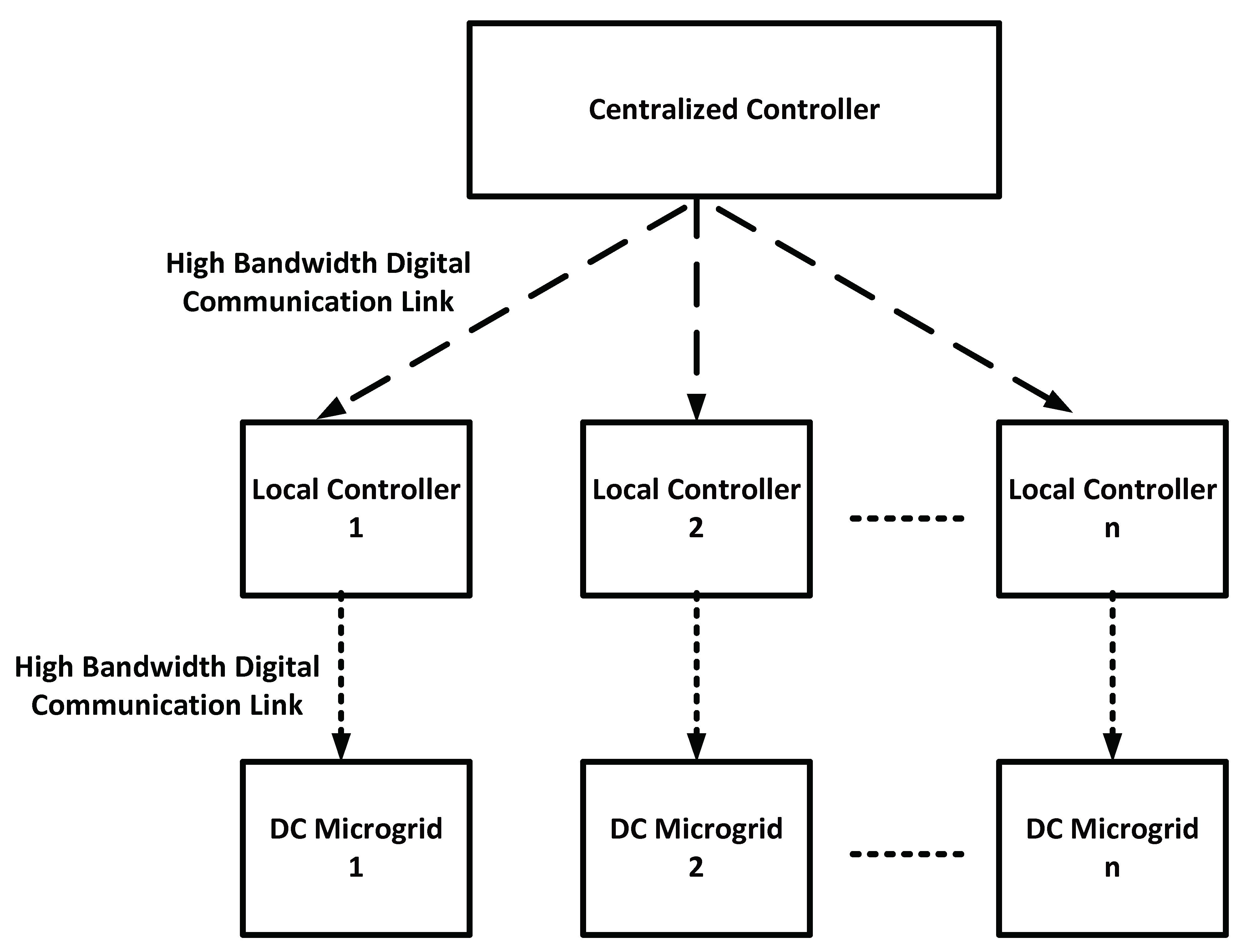
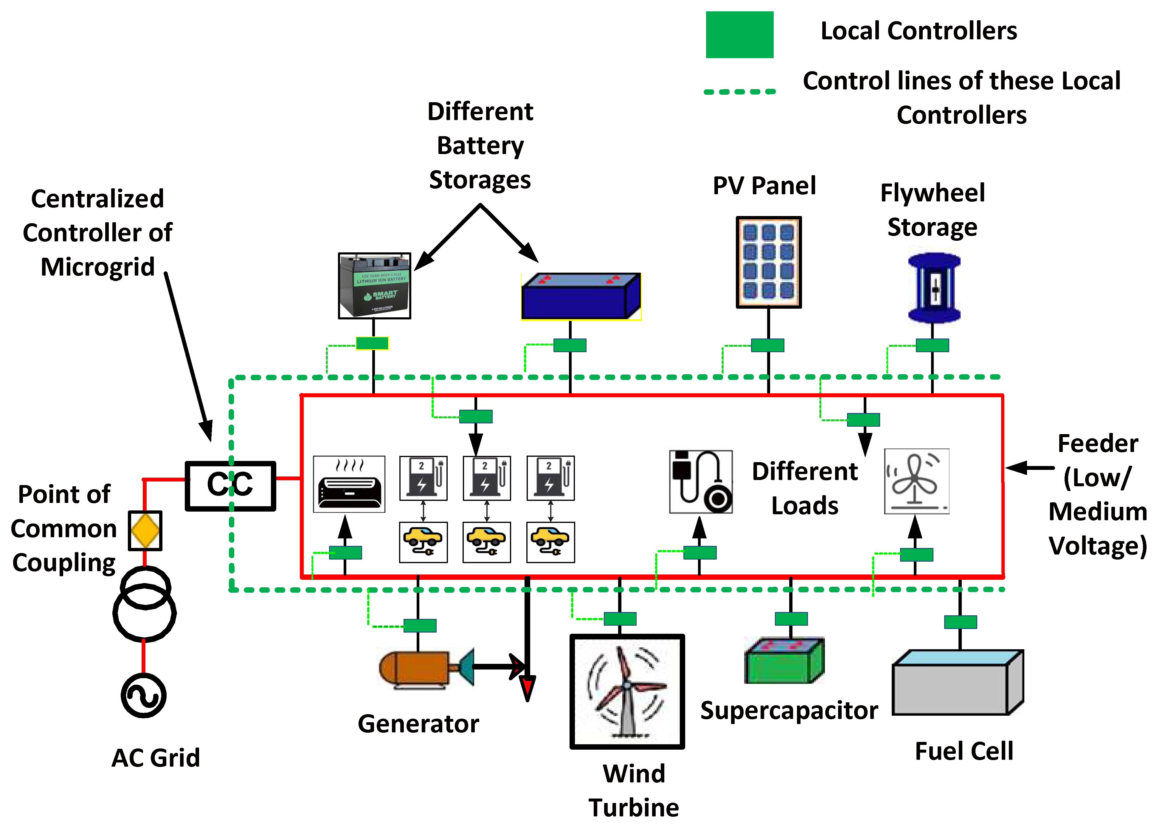
6.3. Centralized Control

If the microgrid is a DC one and uses a central generator, it has to be controlled from one location. Connected users are the building blocks of this network. The data and profiles of all users are stored in a single, easily accessible database. This data could be associated with a user’s account or with some other piece of user-generated content or data. It is easy to make and explain a unified structure. It is most useful to think of it as a DC microgrid due to the way its power sources and loads are connected (through a centralized controller and an automated communication network). A hierarchical control structure is ideal for a large DC microgrid due to the additional layers of protection it provides. This organizational setup delineates the various levels of management. When compared to centralized control, the reliability of hierarchical-type control is higher because it continues to operate even if the central controller fails. Control mechanisms are necessary for a DC microgrid because of problems with voltage regulation on the DC bus, poor power quality, and uneven load distribution. To address these issues and guarantee some degree of control is maintained in the event of a centralized system failure, it is generally accepted that hierarchical control systems are necessary. Nothing has changed, and it still performs as expected [98,99,100]. The basic architecture of DC microgrid having centralized control has been shown in Figure 8.

6.4. Hierarchical Control

The components and structure of the command structure are graphically represented. The architecture classifies them as either “tertiary”, “secondary”, or “primary” commands. The electrical system regulates the flow of current and voltage. When combined with voltage compensation, secondary control improves current sharing beyond that of primary control [101].
Primary Control
The direct current (DC) microgrid is an essential tool for managing the interaction between generators and consumers. Primary controls include the inner loop and droop. By using an internal feedback loop, the voltage and current may be kept under check. In a microgrid, traditional droop controls are included in the droop mechanism. The droop approach is used to design local controls for the various sources to guarantee the most effective and dependable usage of those sources. The central command is in communication with the local controllers through a low-bandwidth networking system [102].
o
Droop Control of Primary Control
DC microgrids often use droop control owing to their adaptability. Microgrid DC buses often employ the droop control method to fine-tune amplitude and power distribution. In a DC microgrid, droop control algorithms are used to manage voltage and current droop separately. The effectiveness and reliability of power-sharing at the state of equilibrium were considered as part of a comparison between the current droop control solution and the voltage droop solution. The reference current is created when the DC bus voltage drops, while the reference voltage is created when the load voltage drops. To achieve optimal regulation, a voltage droop control strategy based on the power supply is used. Droop control methods allow for more efficient and equitable regulation of the system’s output power while also facilitating the sharing of this resource. Droop control is a basic control method that enhances the performance of a solar unit and adjusts the unit’s output power without the requirement for complete power measurement. In a power grid isolated from the rest of the world that relies on a wide variety of renewable energy sources, it is essential to not only reduce energy consumption but also to manage load and renewable energy supply. Since droop control for DC systems has no single point of failure and simply needs information about the bus voltage, it is more dependable than other control schemes [103].
Conventional droop control
Power and potential (or potential and current) are used together as the regulating variable in the basic droop control approach. Droop characteristics control methods are used to manage the output voltage of the power converter in a microgrid. Two droop control methods for a DC microgrid with voltage source management were examined for their power-sharing capacities and stability. Each terminal’s injecting current is individually controlled by a DC current controller in response to a readout of the terminal’s voltage in current mode droop control. The terminal voltage is maintained using the current-based potential mode droop power. When using droop control on a DC microgrid, electricity is distributed more evenly as the output current rises, since the voltage relation falls more steeply. However, there are a few things to keep in mind when employing droop control as a decentralized solution for load power sharing. Proportional Integral (PI) controllers average the voltage and current to restore the local DC output voltage and improve the precision with which the load current is split [104].
Advanced droop control
Different droop features are analyzed to boost the system’s efficiency. The inverse droop control architecture is effective in balancing load regulation and cost. Inverse droop regulation is proposed to increase the output voltage [104].
Inverse droop control
Inverse-droop decentralization of control may be useful for modular devices that have input sequence output parallelism. It is feasible to divide responsibilities fairly. The control’s power-sharing properties, such as the way it divides up input and output current, are amenable to both steady-state and transient analysis. Additionally, the usefulness of the performance-regulating feature may be enhanced. This is because the output voltage does not rely on the input voltage [105].
Non-Linear Droop Control
To provide better load sharing and voltage regulation, non-linear droop topology DC systems were designed. The use of variable droop resistance is proposed as an alternative to the more conventional option of continuous droop resistance. The droop resistance value is set by the output current. The resistance to sagging increases as the load is reduced. It does this by increasing load sharing at high loads and enhancing voltage balancing at low loads. This approach does away with a problem with the more common droop technique.
With the advent of non-linear droop control, the traditional tension between voltage management and load sharing has been greatly alleviated. Three distinct non-linear droop control algorithms were conceived of, studied, and created to enhance the precision of current sharing and the robustness of the system. If many droop curves have different droop gains, load sharing could be improved by using a droop curve with a higher degree of polynomiality to match the gains. Polynomial droop gain methods have proven to be the most reliable for voltage regulation. The polynomial droop curve method provides reliable voltage management and effective load sharing over a wide range of situations [105].
Dead Band Droop Control
The significant breakthrough mandated the “offline” mode of operation for lithium-ion rechargeable batteries due to the dead-band droop characteristic of these batteries. The need for charging and discharging is reduced by operating in a floating or standby mode. Control mechanisms for battery-based energy storage systems can be calibrated to the system’s nominal value via droop control. The adaptive droop function of the energy storage system minimizes dead band failures and reduces unnecessary switching noise, both of which contribute to greater device stability [106].
Adaptive droop control
Primary controllers can respond quickly and independently to faults, changes in load, and other disruptions when using an adaptive droop system. Power optimization at the main control layer requires an adaptive droop method that allows for local controllers to work effectively and dynamically in the face of disturbances like failures, changes in load, and variations in external conditions. Reference voltages allow for finer-grained regulation of power distribution to accommodate users with varying priorities for resource conservation and efficiency. Because of it, the voltage is consistent, and the loads are evenly distributed. Voltage reference points are modified by a control hierarchy to maximize efficiency. It helps with power regulation and load balancing. Responsibility will be removed by appointing a new leader to this position. The voltage and power distribution can be fine-tuned with greater precision by adjusting the continuous droop as opposed to the smaller or larger droop controls. The gain of the droop is enhanced by increasing the current-sharing output of the analog circuit. To counteract the higher droop gain, the voltage is stepped up at regular intervals. With droop gain, you can rest assured that the voltage and current will be distributed properly. Droop gains are load-dependent and are updated in real-time [105,106,107].
Inner Loop
The inner loop does the work of rectifying the DC current and converting it to another form. In many AC to DC converters, the current controller is situated on the loop side. Since the current controller’s output current is the most stable in relation to the reference and it quickly converges to the point of equilibrium with the power factor at unity, it can be used to generate a pulse-width-modulated switching signal. Keeping the current controller in place is the best bet for expanding the system’s capabilities. There are two distinct control modes for a DC/DC converter: voltage control and current control. The DC/DC converter can serve as both a voltage reference and a voltage source by entering voltage control mode. When the converter is set to control current or power, it functions as a regulated power supply.
Secondary Control
In DC microgrids, the primary controller is insufficient because of the grid’s poor voltage regulation and power distribution. When dealing with large line resistances over extended feeds, it has been found that the primary controller is particularly useless. This is why numerous controllers are employed in the hierarchical method. Any of the primary controllers could serve as the secondary controller in this setup, with the latter’s responsibility being to supply the former with voltage and current reference signals. Reliability, power sharing, voltage management, and power quality can all benefit from reference signals provided from the secondary controller to the primary controller. Since the secondary controller assumes that all loads are in a single location, it can maintain a consistent voltage throughout the system. A centralized controller keeps tabs on the DC bus voltage and reports back to the voltage regulators. Some people have doubts about the stability and dependability of the controller’s central communication link to the devices it controls [108]. As a result, some tertiary controllers resort to distributed control. This method is used for inter-converter communication by sending predetermined bus voltages to nearby converters. When the primary controller fails, the secondary controller takes over. It is demonstrated that secondary controllers can be constructed from the standard voltage and current. The data are collected by average current and voltage controllers, which then use it to make more informed decisions about current and voltage. Larger voltage swings due to mismatched line impedance make droop management unfeasible for DC microgrids using extended DC cables. We propose a consensus-based technique for a distributed secondary controller to replace the conventional droop control. In addition, the hierarchical approach employs the decentralized controller as a supplementary controller. The advantages of a decentralized controller over a centralized one are more efficiency and less complexity. Its primary function is to manage individual converters based on data collected in the surrounding area. The distributed method may be simple to build for the secondary controller, but it could compromise performance if the error correction term provided is insufficient [109].
Centralized Control
A DC microgrid serves as the foundation for the centralized controller that establishes connections between the data network and the input sources and loads. The voltage of each module can be regulated independently in its totality by means of network communication with a master controller. Control systems that are very complicated are necessary for power and energy management in microgrids that receive a considerable percentage of their power from solar panels [110,111]. This is because microgrids with this type of power generation structure are more difficult to control. The suggested technique incorporates not only a hierarchical control structure but also three distinct levels, which allows for load balancing and regulation of the voltage as well as components of the system. When used in the process of secondary voltage regulation, the utilization of a PI controller makes it possible to forestall the occurrence of voltage droop. The reference provides further command and control over the signaling that is executed on the bus of the DC microgrid on an islanded mode [112].
Decentralized Control
Indicators at the regional level are used to coordinate rules in decentralized systems. When connectivity between the various sources is not necessary, adding a centralized controller to the device can further improve its ability to carry out its functions. During the secondary control stage, the proportional controller will make the necessary adjustments to account for the impedance effect. Multiple control devices are dispersed across a region to perform computations and transmissions. Using approximation gain to eliminate line impedance is necessary for ensuring uniform power delivery. Each module’s individual reference voltage is taken into consideration by means of a forward feed term. A separate voltage controller for figuring out the load current is not required if the bus voltage and the load current are well-matched. The microgrid supplies electricity to multiple connected loads. Since this load provides energy to all other loads, it is essential to monitor the current flowing through it [113,114].
Distributed Secondary Control
Without a central command and control node, dispersed methods are still recommended. As a result of taking this course of action, the gadget can continue to operate correctly even if certain lines of connection are suddenly cut. In contrast to centralized control, only accessible variables are present during direct information transfer between local controllers. Because of the inability to coordinate between the two groups. Access to the monitoring data is restricted. To address this issue, we employ DC bus signaling, shared current and voltage, and cooperative problem-solving [115].
Voltage Current Sharing Control
To regulate the current and voltage, a PI controller is employed, but this time with enhanced droop characteristics. When a load is increased, the resistance of all droop lines shifts in the same direction, so the inaccuracy of the lines is reduced. Due to the effort necessary to calculate the average current and detect the shift gain, the three PI controllers may be cumbersome to deploy as a supplemental control tool. Distributed control methods can be used to determine the overall amount of energy (in kilowatt-hours) stored in the batteries. The average current controller allows for fine-tuning of the droop gain. Due to the voltage loss that occurs when compensating for shared loads, a unified compensation strategy is recommended. The secondary control system will often boost the droop gain to keep the power constant. To perform distributed secondary control with a low-bandwidth communication link, it is recommended to use a primary controller and an average control signal derived from measurements [116].
DC Bus Signaling
Using a DC bus and a distributed control signaling technique, solar energy can be stored for later use. Voltage bus signaling, which acts as an information carrier, regulates the transition between modes. Constant-voltage operation and peak-power tracking can be attained with the help of modular DC converters, which control the voltage of the DC bus [116].
Synergistic Control
The optimal voltage can be achieved by activating the cooperative control mechanism. Instead of using a conventional current and voltage regulator, a loop droop is used to fine-tune the voltage and current levels of the shared load. Decentralized control systems are required for voltage regulation on a DC microgrid bus. This is crucial in finding a happy medium between energy storage and a distributed controller. To achieve optimal current distribution, a microgrid-based hierarchical distributed control scheme combined with negative current sharing is used. To regulate the operation of several distributed generators, a microgrid employs a consensus mechanism. Distributed generation in a microgrid uses a consensus-based distributed control system to keep data in sync. Voltage and power quality can be precisely controlled by using a DC electric spring in a DC microgrid. To distribute energy among the various batteries and ultra-capacitors in a direct current (DC) microgrid without a centralized controller, a multi-cooperative control technique is used. A cooperative control technique is utilized because of the frequent failure of both the converter and the communication network. Advantages include lower voltage, current, and thermal strains [116,117].
Tertiary Control
To put it simply, the main control in a hierarchical control architecture does not have access to the secondary controls or vice versa. The DC bus voltage will be controlled and shared across the microgrid systems. Secondary control will use droop control of lower bandwidth communication to correct any voltage fluctuations. A centralized controller will be unable to regulate power flow if there is a significant voltage difference. A distributed controller is employed to address the problems. Third-level control strategies in microgrids gather data on generation and loads and use that information to run the grid efficiently and economically. While linked to the mains, it will keep tabs on the microgrid’s resources and regulate them to keep costs down [118].
DC microgrids require careful planning and management due to the many factors involved in their creation and maintenance. Inefficient DC microgrid planning, on the one hand, has a major impact on the operation. In contrast, the strategy’s implementation significantly affects the microgrid’s dependability and stability. DC microgrids can either operate autonomously or link up with the larger electrical grid. Strategically situating generating units that are visible and load may boost system dependability in a disconnected DC microgrid caused by a fault, voltage fluctuations, or other disruptions to the main grid. During the design phase of the microgrid, initial costs, ongoing operational and maintenance costs, and planned outages must all be accounted for. To calculate the return on an investment over a year, one uses an annual rate, while for a shorter time frame, one uses an hourly rate. The reliability index determines the total amount of money that is expected to be spent on increasing reliability over the planning horizon. Microgrids use a wide variety of generation mixes, including photovoltaic (PV) panels, wind turbines, fuel cells, supercapacitors, batteries, direct current (DC) loads, intelligent loads, and EV chargers. The microgrid plan in the base case, the sensitivity analysis of the DC loads ratio, the critical load analysis, and the market price analysis are all considered. To locate and quantify DERs, mathematical model could be employed. Nevertheless, renewable energy sources are impractical because of output fluctuations. The ideal location and size of a microgrid are determined using a mixed-integer non-linear programming model. The algorithm starts with a heuristic phase where the topology of the microgrid, ideal equipment size, and location are selected. The algorithm includes a section that is responsible for ensuring a steady exchange of power between the microgrids. However, the radial microgrids network is treated as if it were static in the programming model. A new model for microgrids is presented, one that considers both the optimally configurated microgrids and the DER sizing, to lower the overall cost of planning [119]. Some of the strategies associated with DC microgrids as a part of tertiary control are discussed further.

6.5. Power Production and Estimation of Demand

DC microgrids necessitate energy management due to the extreme cyclicity of renewable energy sources. When it comes to cost efficiency, DC microgrids rely heavily on the power variation in renewable sources. Therefore, DC microgrids, where a large share of renewable energy is expected, are the primary focus of renewable energy forecasting. To cut down on expenses and power losses, we present a method for predicting the output of renewable energy sources using a back propagation neural network trained with a variant of particle swarm optimization. The optimization results are used to combine various hybrid DGs into DC microgrid models. DC microgrids are vulnerable to instability due to changes in the load profile. These, along with other developments like the production of renewable energy, highlight the importance of load forecasting. The EMS cannot develop effective dispatch plans unless it has reliable predictions of renewable energy generation and load. Microgrid load forecasting was performed using a Markov chain Monte Carlo simulation. The current approach of forecasting takes into consideration a variety of parameters, such as solar photovoltaic (PV), energy storage systems used for microgrids, essential loads, residential loads, and more. The use of a long short-term memory (LSTM) system developed by support vector regression has significantly improved the accuracy with which microgrid load predictions may be made in off-grid regions. The inputs are the various commercial and residential building types, and the outputs are the resulting load profiles. A model for predicting microgrid load based on an artificial neural network is used. Hourly load data from the previous day, weekday, and month are inputs into the forecasting model. Most predictions for microgrid renewable energy are based on weather data, which is itself derived using a forecasting method. A forecasting method that depends on the results of another method is therefore doomed to failure. A persistence method that uses historical power data rather than weather data is presented to forecast loads and renewable energy. The literature has also covered fuzzy logic, statistical approaches intelligent algorithms, and adaptive neuro-fuzzy inference systems as additional approaches for load and generation forecasting [120].

6.6. Enhancement of Energy Storage Capacity

DC microgrids, however, present a security risk because renewable energy sources are unpredictable. Instead, energy storage-based DC microgrids are better for the environment, the wallet, the long term, and the grid’s overall reliability. A microgrid’s design must carefully consider various energy storage options, including batteries, supercapacitors, magnetic super-conducting energy storage (SMES), pumped storage, flywheel storage, and others. In favor of minimizing capacity through optimal sizing of energy storages, much of the existing literature ignores other critical issues. This highlights the need for a comprehensive analysis to guide researchers and businesspeople toward the optimal sizing of ESSs considering a wide range of factors. Numerous studies have divided the problem of optimal ESS sizing into several related issues, including an optimization issue based on multi-objectives and single objectives. When there is only one optimization goal to be met, most problems center on finding ways to cut costs. However, the goal of ESS multi-objective sizing is to maximize reliability while minimizing cost and consumption and maximizing the lifespan of the system. Multi-objective ESS sizing aims to find the sweet spot where system dependability, cost, energy consumption, and lifespan can all be maximized. The optimal sizing of batteries, SMES, hydrogen storage, and flywheel storage, among other energy storage devices, is determined using heuristic methods such as grey-wolf optimization (GWO), differential evolution (DE), particle swarm optimization (PSO), and genetic algorithm (GA), as well as probabilistic approaches and mixed-integer linear programming [121,122].

7. Challenges Associated with DC Microgrid for Advocacy towards Smart Cities

DC microgrids have a greater edge over AC microgrids, including simpler integration of renewable energy sources, direct consumer load connection, and no frequency or reactive power regulation. However, both frequency and reactive power can be regulated in AC microgrids. Although DC-powered microgrids have many benefits, they also have some drawbacks. There are many causes for the increased uncertainty. Power and SOC imbalances, excessive fault current owing to short circuits, and erratic wind speeds and irradiance are just a few examples of the many problems that can arise in solar power systems. DC microgrids need meticulous planning and management to keep their adaptability, dependability, and stability. However, constant innovation in methods and materials is required considering recent challenges in constructing DC microgrids. To address these issues, experts are developing novel approaches to optimization, DC bus voltage restoration, and other forms of improvement. The methods could be useful in a variety of settings, including strategic planning, operational efficiency, and command and control. There needs to be more research done into the optimal ways to design, operate, and regulate DC microgrids [119].
Accurate modeling is crucial for DC microgrid planning and management. Therefore, to reduce the financial burden of microgrid planning and maintenance, a new or improved model is needed that accounts for the inherent uncertainty of the integrated DGs. Many DC microgrid planning models have been created, but they all have significant shortcomings. More study is needed to better plan DC microgrids for real-time operations. It is possible to modify or improve adaptive, model-predictive, robust, and optimal control approaches in order to provide real-time power sharing and efficient management of DC bus voltage in microgrids. DC link faults remain a worry, even though rethinking and strengthening controllers can have a good influence on the stable and trustworthy functioning of DC microgrids. This is owing to the quick discharge of DC-link capacitors in the presence of short circuit faults. We now require knowledge of fault-blocking technology and strategies for protecting DC links [120]. When large amounts of RES are integrated into a DC microgrid, voltage control performance diminishes because the grid’s overall inertia drops. While solutions have been found, more research is needed before DC microgrids can operate on renewable energy alone. Microgrids are like conventional grids in terms of DC link voltage management. The capacitors in the DC connection supply energy to the inductors, which in turn power the inverter’s AC output. The DC bus voltage in a microgrid can be regulated by a variety of means. There have not been nearly enough studies to address several challenges. DC microgrids regulate DC voltage and manage power with different energy storage systems. The problem is that researchers rarely think about how long these storage devices will last. Longer-lasting energy storage devices can be studied to better maintain the power balance and restore DC bus voltage [121].

8. Optimal Operation and Effectiveness of a DC Microgrid

The economics of operation and control take on greater significance as DC microgrids grow in popularity to provide reliable, low-cost power to clients. Increasing productivity, decreasing operational expenses, and optimizing personnel scheduling are all ways to manage a business profitably. Even though line losses account for 5% of total system losses, they are disregarded by the multi-objective optimization-based scheduling that keeps the DC microgrid running effectively and affordably. For reliable operation of a DC microgrid that accounts for the impact of intermittent energy sources, a stochastic approach is given. Power is sent to the generator with the lowest total cost, which is determined by averaging the costs of all the neighboring units. Using a mathematical optimization model for economic dispatch with semi-definite programming allows for optimal operation with a high penetration of various sources and energy storage devices. Using an optimal scheduling model that considers operation costs, emissions, and power loss, we can devise a cost-effective power strategy for the DC microgrid’s generators. The authors explore several equality and inequality criteria to determine the best method of load sharing in a DC microgrid with fully distributed control. The distributed control system’s communications network is used to update the estimated voltage and operating costs for neighboring grids. Using power forecasts and technological limitations, the optimization challenge seeks to lessen operational costs in microgrids that rely on variable power generation. To help reduce expenses while factoring in the price of DG generation and the utility rate, economic droop control is effective. To maximize the system’s efficiency, scientists used a cost function that factors in the rates charged by the utility for responding to customers’ demands. Using a genetic algorithm, we optimized the parameters of the droop control to save maintenance costs. This reference primarily focuses on minimizing generating costs in a DC microgrid while in both grid-connected and islanded modes by utilizing a combined sub-gradient algorithm and incremental rate criterion. Clusters of DC microgrids are far more difficult to plan economically and logistically than autonomous systems. A Lagrange multiplier-based online power flow optimization technique was developed for a DC microgrid to enable efficient operation at a reasonable cost. Due to their increasing popularity, studies into the economics of DC microgrids’ operation and economic control measures are urgently needed [120,121].

9. Applications of a DC Microgrid

9.1. Domestic Applications

Direct current (DC) loads and sources are responsible for the largest bulk of today’s energy consumption, and this occurs now when the energy is being used. When performance is improved by using direct current rather than alternating current, this is because direct current can be utilized immediately. In addition, a wide variety of options for the management of energy are available in DC systems, but these options are unavailable in AC and hybrid grids. Homes that are DC-powered and exceptionally energy efficient will be important enablers of future smart grids. These kinds of homes are now being researched in several countries all over the world. Two of the most fundamental goals of smart grid programs are to integrate different types of alternative energy sources and to provide consumers with more control over their energy consumption. Increasing the number of storage units and intelligent home devices both contribute to an increase in the level of reliability that the networks provide. Individual residences may be managed as part of a larger group to cut down on the quantity of space required for storage, boost the level of dependability, and make the procedure of power distribution and consumption more straightforward [120,121].

9.2. Renewable Energy Parks

It is possible to construct renewable energy parks by joining many sources that are connected by DC buses. In order to generate power in this setting, several solar photovoltaic or wind turbine generators are connected in parallel. These networks, which are sometimes referred to as collector grids, are the most effective way to gather energy from renewable sources such as the sun and the wind. The control and management of such grids require a far more comprehensive suite of auxiliary services than is required for residential applications. This is necessary so that the grid can run in accordance with the rules that now govern grids [122].

9.3. Fast Charging Stations for Electric Vehicles

Electric and plug-in hybrid electric vehicles spark conversations about grid backup, emergency electricity to buildings, and system stability. The current issues surrounding fossil fuels have piqued interest in electric vehicles (EVs) around the world. There is a pressing need for more charging stations as the number of electric vehicles on the road increases. Most vehicles may be charged to 80% capacity in 15 to 45 min using DC quick charging. The standard AC charging station can take many hours, while this one only needs a few. A variety of DC energy sources can be interfaced with charging stations that support vehicle-to-grid (V2G) and grid-to-vehicle (G2V) modes, boosting the system’s dependability. V2G and G2V are the abbreviations for these two modalities. Many other energy-storage technologies exist and can be considered in addition to flywheels and batteries [123].

9.4. Support Systems in Data Centers

Multiple interconnected networks supply electricity to the many servers and other IT hardware installations typically found in data centers. The largest consumers of electricity in data centers are the servers and other IT equipment, as well as the energy end-use infrastructures (HVAC, UPS, lighting, communications, etc.). Data centers are probably only functional approximately 30% of the time. The research shows that by using direct current (DC) to power IT equipment, data centers can reduce their electricity costs and increase their profits by skipping multiple power conversion processes. This results in less wasted energy use by the data centers’ IT hardware [124,125,126,127].

10. Discussions and Future Trends

DCMG structure research is widespread. Design and architecture determine the power system’s hierarchy, scalability, controllability, sturdiness, and controllability. Single-bus, multi-bus, multi-terminal, Ring-bus, Ladder-bus, and Zonal DCMG structures are compared to each other and other MG structures. These structures have various functions and constraints. More research is needed to fix their flaws, add redundancy, and simplify DCMG frameworks. Controls might be basic or complex. The communication link determines whether control is centralized, decentralized, or distributed. DCMG’s decentralized units gather, process, and send information to DCLs in centralized control. Centralized master-slave control has been extensively studied. Decentralized control is considered the safest because it requires no communication between system components. Droop and DBS decentralized control methods have been discussed. Distributed controllers only connect with neighboring units via their limited DCLs. Consensus and agent-based distributed control techniques are examined. A single controller, centralized or decentralized, cannot achieve both basic objectives like voltage, current, and power control and advanced objectives like power sharing between DGs, Power Quality control, ancillary services, energy market participation, operating cost minimization, etc. DCMGs in this mode are believed to use multilevel control. Hierarchical control and layer functions are examined here. Centralized control is used in secondary and above-level control due to its single point failure and complexity. Several authors have tried to make distributed control suitable for higher-level control in multilevel control systems. Distribution control involves extensive research for secondary and higher management. Distributed control strategies involve extensive mathematical investigation. Small-signal-based linear controls like droop control and master-slave control may fail when used to global MG systems. Fuzzy, neural, Lyapunov-function, and other nonlinear control techniques may solve this problem. Before real-time application, complicated control systems need extensive research. Power management maintains the DC bus voltage with an energy storage system and the utility grid (if the system is connected). MG cluster power and energy management needs more research. DC distribution systems may soon use distributed secondary control with DBS power management. Before robust power management approaches can be applied for grid-connected, islanded, and transient modes, many difficulties must be tackled. SST allows flexible DCMG interaction with the electric grid. The EMS must consider storage device power losses, SOC response time, power-energy restrictions, and DG power projections. Energy management maximizes energy storage system efficiency, extends their lifespans, and meets critical electrical loads. Energy management approaches are addressed. All battery and supercapacitor HESS setups and their energy management pros and downsides have been examined. HESS systems require nonlinear power allocation algorithms since linear filters are insufficient. Sizing renewable energy system components affects hybrid energy storage system development cost. Most systems are overblown because they lack a systematic strategy to identify system components.

11. Conclusions

This paper was intended for both experts and the public to learn more about DC microgrids and their many uses. An overview was presented of DC microgrid applications, economic operation and control, microgrid configuration comparison, and global state-of-the-art DC microgrid projects, as well as a discussion of emerging trends in DC microgrid research. Different DC microgrid topologies have been researched for their unique communication and protection requirements. Despite DC microgrids’ widespread use and bright future, substantial obstacles in design, operation, and control must be met. As RES becomes more commonplace, grid power balance, energy management, and DC link voltage regulation will become increasingly crucial.

Author Contributions

Conceptualization, S.S.R., A.S.; methodology, S.S.R.; software, S.S.R.; validation, S.S.R. and R.R.; formal analysis, S.S.R. and R.R.; investigation, S.S.R. and R.R.; resources, S.S.R.; data curation, S.S.R.; writing—original draft preparation, S.S.R., R.R. and A.S.; writing—review and editing, S.S.R. and R.R.; visualization, S.S.R.; supervision, S.S.R., P.K.S., R.K., C.K.S., E.R.C. and T.S.; project administration, S.S.R., A.S. All authors have read and agreed to the published version of the manuscript.

Funding

The authors received no external funding.

Data Availability Statement

Not applicable.

Conflicts of Interest

The authors declare no conflict of interest.

References

  1. Fotopoulou, M.; Rakopoulos, D.; Trigkas, D.; Stergiopoulos, F.; Blanas, O.; Voutetakis, S. State of the Art of Low and Medium Voltage Direct Current (DC) Microgrids. Energies 2021, 14, 5595. [Google Scholar] [CrossRef]
  2. Fernández, G.; Galan, N.; Marquina, D.; Martínez, D.; Sanchez, A.; López, P.; Bludszuweit, H.; Rueda, J. Photovoltaic Generation Impact Analysis in Low Voltage Distribution Grids. Energies 2020, 13, 4347. [Google Scholar] [CrossRef]
  3. Moret, F.; Pinson, P. Energy Collectives: A Community and Fairness Based Approach to Future Electricity Markets. IEEE Trans. Power Syst. 2019, 34, 3994–4004. [Google Scholar] [CrossRef] [Green Version]
  4. Rodríguez-Molina, J.; Martínez-Núñez, M.; Martínez, J.-F.; Pérez-Aguiar, W. Business Models in the Smart Grid: Challenges, Opportunities and Proposals for Prosumer Profitability. Energies 2014, 7, 6142–6171. [Google Scholar] [CrossRef] [Green Version]
  5. Arboleya, P.; Koirala, A.; Suarez, L.; Mohamed, B.; Gonzalez-Moran, C. Impact Evaluation of the New Self-Consumption Spanish Scenario on the Low-Voltage Terminal Distribution Network. IEEE Trans. Ind. Appl. 2019, 55, 7230–7239. [Google Scholar] [CrossRef] [Green Version]
  6. Schick, C.; Klempp, N.; Hufendiek, K. Impact of Network Charge Design in an Energy System with Large Penetration of Renewables and High Prosumer Shares. Energies 2021, 14, 6872. [Google Scholar] [CrossRef]
  7. Tushar, W.; Saha, T.K.; Yuen, C.; Smith, D.; Poor, H.V. Peer-to-Peer Trading in Electricity Networks: An Overview. IEEE Trans. Smart Grid 2020, 11, 3185–3200. [Google Scholar] [CrossRef] [Green Version]
  8. Herrera, M.L.; Hayajneh, H.S.; Zhang, X. DC Communities: Transformative Building Blocks of the Emerging Energy Infrastructure. Energies 2021, 14, 7730. [Google Scholar] [CrossRef]
  9. Mackay, L.; Hailu, T.; Ramirez-Elizondo, L.; Bauer, P. Towards a DC Distribution System—Opportunities and Challenges. In Proceedings of the 2015 IEEE First International Conference on DC Microgrids (ICDCM), Atlanta, GA, USA, 7–10 June 2015. [Google Scholar] [CrossRef]
  10. Castillo-Calzadilla, T.; Cuesta, M.A.; Olivares-Rodriguez, C.; Macarulla, A.M.; Legarda, J.; Borges, C.E. Is It Feasible a Massive Deployment of Low Voltage Direct Current Microgrids Renewable-Based? A Technical and Social Sight. Renew. Sustain. Energy Rev. 2022, 161, 112198. [Google Scholar] [CrossRef]
  11. Vossos, V.; Gerber, D.L.; Gaillet-Tournier, M.; Nordman, B.; Brown, R.; Heredia, W.B.; Ghatpande, O.; Saha, A.; Arnold, G.; Frank, S.M. Adoption Pathways for DC Power Distribution in Buildings. Energies 2022, 15, 786. [Google Scholar] [CrossRef]
  12. Zhang, F.; Meng, C.; Yang, Y.; Sun, C.; Ji, C.; Chen, Y.; Wei, W.; Qiu, H.; Yang, G. Advantages and challenges of DC microgrid for commercial building a case study from Xiamen university DC microgrid. In Proceedings of the IEEE First International Conference on DC Microgrids (ICDCM), Atlanta, GA, USA, 7–10 June 2015; pp. 355–358. [Google Scholar] [CrossRef]
  13. Trivedi, R.; Patra, S.; Sidqi, Y.; Bowler, B.; Zimmermann, F.; Deconinck, G.; Papaemmanouil, A.; Khadem, S.; Microgrids, C.-B. Community-Based Microgrids: Literature Review and Pathways to Decarbonise the Local Electricity Network. Energies 2022, 15, 918. [Google Scholar] [CrossRef]
  14. Nasir, M.; Khan, H.A.; Hussain, A.; Mateen, L.; Zaffar, N.A. Solar PV-Based Scalable DC Microgrid for Rural Electrification in Developing Regions. IEEE Trans. Sustain. Energy 2018, 9, 390–399. [Google Scholar] [CrossRef]
  15. Madduri, P.A.; Poon, J.; Rosa, J.; Podolsky, M.; Brewer, E.A.; Sanders, S.R. Scalable DC Microgrids for Rural Electrification in Emerging Regions. IEEE J. Emerg. Sel. Top. Power Electron. 2016, 4, 1195–1205. [Google Scholar] [CrossRef]
  16. Richard, L.; Boudinet, C.; Ranaivoson, S.A.; Rabarivao, J.O.; Befeno, A.E.; Frey, D.; Alvarez-Hérault, M.-C.; Raison, B.; Saincy, N. Development of a DC Microgrid with Decentralized Production and Storage: From the Lab to Field Deployment in Rural Africa. Energies 2022, 15, 6727. [Google Scholar] [CrossRef]
  17. Phurailatpam, C.; Rajpurohit, B.S.; Wang, L. Planning and optimization of autonomous DC microgrids for rural and urban applications in India. Renew. Sustain. Energy Rev. 2018, 82, 194–204. [Google Scholar] [CrossRef]
  18. Elsayed, A.T.; Mohamed, A.A.; Mohammed, O.A. DC Microgrids and Distribution Systems: An Overview. Electr. Power Syst. Res. 2015, 119, 407–417. [Google Scholar] [CrossRef]
  19. D’agostino, F.; Kaza, D.; Martelli, M.; Schiapparelli, G.-P.; Silvestro, F.; Soldano, C. Development of a Multiphysics Real-Time Simulator for Model-Based Design of a DC Shipboard Microgrid. Energies 2020, 13, 3580. [Google Scholar] [CrossRef]
  20. Al Amerl, A.; Oukkacha, I.; Camara, M.B.; Dakyo, B. Real-Time Control Strategy of Fuel Cell and Battery System for Electric Hybrid Boat Application. Sustainability 2021, 13, 8693. [Google Scholar] [CrossRef]
  21. Shekhar, A.; Ramirez-Elizondo, L.; Bauer, P. DC microgrid islands on ships. In Proceedings of the 2017 IEEE Second International Conference on DC Microgrids (ICDCM), Nuremberg, Germany, 27–29 June 2017; pp. 111–118. [Google Scholar] [CrossRef] [Green Version]
  22. Faddel, S.; Saad, A.A.; Mohammed, O. Decentralized Energy Management of Hybrid Energy Storage on MVDC Shipboard Power System. In Proceedings of the 2018 IEEE Industry Applications Society Annual Meeting (IAS), Portland, OR, USA, 23–27 September 2018; pp. 1–7. [Google Scholar]
  23. Jayasinghe, S.G.; Meegahapola, L.; Fernando, N.; Jin, Z.; Guerrero, J.M. Review of Ship Microgrids: System Architectures, Storage Technologies and Power Quality Aspects. Inventions 2017, 2, 4. [Google Scholar] [CrossRef] [Green Version]
  24. Menicanti, S.; di Benedetto, M.; Marinelli, D.; Crescimbini, F. Recovery of Trains’ Braking Energy in a Railway Micro-Grid Devoted to Train plus Electric Vehicle Integrated Mobility. Energies 2022, 15, 1261. [Google Scholar] [CrossRef]
  25. Ceraolo, M.; Lutzemberger, G.; Meli, E.; Pugi, L.; Rindi, A.; Pancari, G. Energy storage systems to exploit regenerative braking in DC railway systems: Different approaches to improve efficiency of modern high-speed trains. J. Energy Storage 2018, 16, 269–279. [Google Scholar] [CrossRef]
  26. Verdicchio, A.; Ladoux, P.; Caron, H.; Courtois, C. New Medium-Voltage DC Railway Electrification System. IEEE Trans. Transp. Electrif. 2018, 4, 591–604. [Google Scholar] [CrossRef]
  27. Perez, F.; Iovine, A.; Damm, G.; Galai-Dol, L.; Ribeiro, P.F. Stability Analysis of a DC MicroGrid for a Smart Railway Station Integrating Renewable Sources. IEEE Trans. Control. Syst. Technol. 2020, 28, 1802–1816. [Google Scholar] [CrossRef]
  28. Pratt, A.; Kumar, P.; Aldridge, T.V. Evaluation of 400V DC distribution in telco and data centers to improve energy efficiency. In Proceedings of the INTELEC 29th International Telecommunications Energy Conference, Rome, Italy, 30 September–4 October 2007; pp. 32–39. [Google Scholar]
  29. AlLee, G.; Tschudi, W. Edison Redux: 380 Vdc Brings Reliability and Efficiency to Sustainable Data Centers. IEEE Power Energy Mag. 2012, 10, 50–59. [Google Scholar] [CrossRef]
  30. Li, X.; Ji, Z.; Yang, F.; Dou, Z.; Zhang, C.; Chen, L. A Distributed Two-Level Control Strategy for DC Microgrid Considering Safety of Charging Equipment. Energies 2022, 15, 8600. [Google Scholar] [CrossRef]
  31. Jayamaha, D.K.J.S.; Lidula, N.W.A.; Rajapakse, A.D. Protection and grounding methods in DC microgrids: Comprehensive review and analysis. Renew. Sustain. Energy Rev. 2020, 120, 109631. [Google Scholar] [CrossRef]
  32. Lu, S.; Yu, T.; Liu, H.; Zhang, W.; Sui, Y.; Yang, J.; Zhang, L.; Zhou, J.; Wang, H. Research on Flexible Virtual Inertia Control Method Based on the Small Signal Model of DC Microgrid. Energies 2022, 15, 8360. [Google Scholar] [CrossRef]
  33. Li, C.; Yang, Y.; Dragicevic, T.; Blaabjerg, F. A New Perspective for Relating Virtual Inertia with Wideband Oscillation of Voltage in Low-Inertia DC Microgrid. IEEE Trans. Ind. Electron. 2022, 69, 7029–7039. [Google Scholar] [CrossRef]
  34. Mao, J.; Zhang, X.; Dai, T.; Wu, A.; Yin, C. An Adaptive Backstepping Sliding Mode Cascade-Control Method for a DC Microgrid Based on Nonlinear Virtual Inertia. Electronics 2021, 10, 3100. [Google Scholar] [CrossRef]
  35. Zhang, Y.; Sun, Q.; Zhou, J.; Li, L.; Wang, P.; Guerrero, J.M. Coordinated Control of Networked AC/DC Microgrids with Adaptive Virtual Inertia and Governor-Gain for Stability Enhancement. IEEE Trans. Energy Convers. 2021, 36, 95–110. [Google Scholar] [CrossRef]
  36. Wang, F.; Sun, L.; Wen, Z.; Zhuo, F. Overview of Inertia Enhancement Methods in DC System. Energies 2022, 15, 6704. [Google Scholar] [CrossRef]
  37. Yang, Y.; Li, C.; Xu, J.; Blaabjerg, F.; Dragicevic, T. Virtual Inertia Control Strategy for Improving Damping Performance of DC Microgrid with Negative Feedback Effect. IEEE J. Emerg. Sel. Top. Power Electron. 2021, 9, 1241–1257. [Google Scholar] [CrossRef]
  38. Sarojini, R.K.; Palanisamy, K.; De Tuglie, E. A Fuzzy Logic-Based Emulated Inertia Control to a Supercapacitor System to Improve Inertia in a Low Inertia Grid with Renewables. Energies 2022, 15, 1333. [Google Scholar] [CrossRef]
  39. Zhu, X.; Meng, F.; Xie, Z.; Yue, Y. An Inertia and Damping Control Method of DC–DC Converter in DC Microgrids. IEEE Trans. Energy Convers. 2020, 35, 799–807. [Google Scholar] [CrossRef]
  40. Pires, V.F.; Cordeiro, A.; Foito, D.; Silva, J.F. Control transition mode from voltage control to MPPT for PV generators in isolated DC microgrids. Int. J. Electr. Power Energy Syst. 2021, 137, 107876. [Google Scholar] [CrossRef]
  41. Al-Tameemi, Z.H.A.; Lie, T.T.; Foo, G.; Blaabjerg, F. Control Strategies of DC Microgrids Cluster: A Comprehensive Review. Energies 2021, 14, 7569. [Google Scholar] [CrossRef]
  42. Yao, Y.; Ertugrul, N. An overview of hierarchical control strategies for microgrids. In Proceedings of the 2019 29th Australasian Universities Power Engineering Conference (AUPEC), Nadi, Fiji, 26–29 November 2019. [Google Scholar]
  43. Yang, Y.; Huang, C.; Xu, Q. A Fault Location Method Suitable for Low-Voltage DC Line. IEEE Trans. Power Deliv. 2020, 35, 194–204. [Google Scholar] [CrossRef]
  44. Hategekimana, P.; Ferre, A.J.; Bernuz, J.M.R.; Ntagwirumugara, E. Fault Detecting and Isolating Schemes in a Low-Voltage DC Microgrid Network from a Remote Village. Energies 2022, 15, 4460. [Google Scholar] [CrossRef]
  45. Seo, H.-C. Development of New Protection Scheme in DC Microgrid Using Wavelet Transform. Energies 2022, 15, 283. [Google Scholar] [CrossRef]
  46. Jithin, K.; Haridev, P.P.; Mayadevi, N.; Kumar, R.H.; Mini, V.P. A Review on Challenges in DC Microgrid Planning and Implementation. J. Mod. Power Syst. Clean Energy 2022, 1–21. [Google Scholar] [CrossRef]
  47. Kim, Y.-J.; Kim, H. Arc extinguishment for DC circuit breaker by PPTC device. In Proceedings of the IEEE International Conference on Industrial and Information Systems (ICIIS), Peradeniya, Sri Lanka, 15–16 December 2017; pp. 1–5. [Google Scholar] [CrossRef]
  48. Karppanen, J.; Kaipia, T.; Nuutinen, P.; Lana, A.; Peltoniemi, P.; Pinomaa, A.; Mattsson, A.; Partanen, J.; Cho, J.; Kim, J. Effect of Voltage Level Selection on Earthing and Protection of LVDC Distribution Systems. In Proceedings of the IET Conference Proceedings, Birmingham, UK, 10–12 February 2015; Available online: https://digital-library.theiet.org/content/conferences/10.1049/cp.2015.0057 (accessed on 30 May 2023). [CrossRef]
  49. Chiang, S.J.; Shieh, H.J.; Chen, M.C. Modeling and Control of PV Charger System with SEPIC Converter. IEEE Trans. Ind. Electron. 2009, 56, 4344–4353. [Google Scholar] [CrossRef]
  50. Dragicevic, T.; Vasquez, J.C.; Guerrero, J.M.; Skrlec, D. Advanced LVDC Electrical Power Architectures and Microgrids: A step toward a new generation of power distribution networks. IEEE Electrif. Mag. 2014, 2, 54–65. [Google Scholar] [CrossRef] [Green Version]
  51. Shafiee, Q.; Dragičević, T.; Vasquez, J.C.; Guerrero, J.M. Hierarchical Control for Multiple DC-Microgrids Clusters. IEEE Trans. Energy Convers. 2014, 29, 922–933. [Google Scholar] [CrossRef] [Green Version]
  52. Balog, R.S.; Krein, P.T. Bus Selection in Multibus DC Microgrids. IEEE Trans. Power Electron. 2011, 26, 860–867. [Google Scholar] [CrossRef]
  53. Chaudhuri, N.R.; Majumder, R.; Chaudhuri, B. System Frequency Support Through Multi-Terminal DC (MTDC) Grids. IEEE Trans. Power Syst. 2013, 28, 347–356. [Google Scholar] [CrossRef] [Green Version]
  54. Pinto, R.T.; Bauer, P.; Rodrigues, S.F.; Wiggelinkhuizen, E.J.; Pierik, J.; Ferreira, B. A Novel Distributed Direct-Voltage Control Strategy for Grid Integration of Offshore Wind Energy Systems Through MTDC Network. IEEE Trans. Ind. Electron. 2013, 60, 2429–2441. [Google Scholar] [CrossRef]
  55. Dragičević, T.; Lu, X.; Vasquez, J.C.; Guerrero, J.M. DC Microgrids—Part II: A Review of Power Architectures, Applications, and Standardization Issues. IEEE Trans. Power Electron. 2016, 31, 3528–3549. [Google Scholar] [CrossRef] [Green Version]
  56. Lu, W.; Ooi, B.T. Multiterminal LVDC system for optimal acquisition of power in wind-farm using induction generators. IEEE Trans. Power Electron. 2002, 17, 558–563. [Google Scholar] [CrossRef]
  57. Lu, W.; Ooi, B.-T. Optimal acquisition and aggregation of offshore wind power by multiterminal voltage-source HVDC. IEEE Trans. Power Deliv. 2003, 18, 201–206. [Google Scholar] [CrossRef]
  58. Dubey, A.; Santoso, S. A Two-Level Topology Design Framework for Reliable Shipboard Power Systems. Inventions 2016, 1, 14. [Google Scholar] [CrossRef]
  59. Baran, M.; Mahajan, N. System reconfiguration on shipboard DC zonal electrical system. IEEE Electr. Sh. Technol. Symp. 2005, 2005, 86–92. [Google Scholar]
  60. Do Park, J.; Candelaria, J. Fault Detection and Isolation in Low-Voltage dc-Bus Microgrid System. IEEE Trans. Power Deliv. 2013, 28, 779–787. [Google Scholar] [CrossRef]
  61. Salomonsson, D.; Soder, L.; Sannino, A. Protection of Low-Voltage DC Microgrids. IEEE Trans. Power Deliv. 2009, 24, 1045–1053. [Google Scholar] [CrossRef]
  62. Berizzi, A.; Silvestri, A.; Zaninelli, D.; Massucco, S. Short-circuit current calculations for DC systems. IEEE Trans. Ind. Appl. 1996, 32, 990–997. [Google Scholar] [CrossRef]
  63. Shuai, Z.; He, D.; Xiong, Z.; Lei, Z.; Shen, Z.J. Comparative Study of Short-Circuit Fault Characteristics for VSC-Based DC Distribution Networks with Different Distributed Generators. IEEE J. Emerg. Sel. Top. Power Electron. 2018, 7, 528–540. [Google Scholar] [CrossRef]
  64. Meghwani, A.; Chakrabarti, S.; Srivastava, S.C.; Anand, S. Analysis of Fault Characteristics in DC Microgrids for Various Converter Topologies. In Proceedings of the 2017 IEEE Innovative Smart Grid Technologies—Asia (ISGT-Asia), Auckland, New Zealand, 4–7 December 2017. [Google Scholar]
  65. Shenai, K.; Shah, K. Smart DC micro-grid for efficient utilization of distributed renewable energy. In Proceedings of the IEEE 2011 EnergyTech, Cleveland, OH, USA, 25–26 May 2011; pp. 1–6. [Google Scholar]
  66. Javed, W.; Chen, D.; Farrag, M.E.; Xu, Y. System Configuration, Fault Detection, Location, Isolation and Restoration: A Review on LVDC Microgrid Protections. Energies 2019, 12, 1001. [Google Scholar] [CrossRef] [Green Version]
  67. Telford, R.D.; Galloway, S.; Stephen, B.; Elders, I. Diagnosis of Series DC Arc Faults—A Machine Learning Approach. IEEE Trans. Ind. Inform. 2016, 13, 1598–1609. [Google Scholar] [CrossRef] [Green Version]
  68. Uriarte, F.M.; Gattozzi, A.L.; Herbst, J.D.; Estes, H.B.; Hotz, T.J.; Kwasinski, A.; Hebner, R.E. A DC Arc Model for Series Faults in Low Voltage Microgrids. IEEE Trans. Smart Grid 2012, 3, 2063–2070. [Google Scholar] [CrossRef] [Green Version]
  69. McCalmont, S. Low Cost Arc Fault Detection and Protection for PV Systems. Contract 303 2013, 3000, 275. [Google Scholar]
  70. Makkieh, A.; Emhemed, A.; Wang, D.; Junyent-Ferre, A.; Burt, G. Investigation of different system earthing schemes for protection of low-voltage DC microgrids. J. Eng. 2019, 2019, 5129–5133. [Google Scholar] [CrossRef]
  71. de Oliveira, T.R.; Bolzon, A.S.; Donoso-Garcia, P.F. Grounding and safety considerations for residential DC microgrids. In Proceedings of the IECON 2014—40th Annual Conference of the IEEE Industrial Electronics Society, Dallas, TX, USA, 29 October 2014–1 November 2014; pp. 5526–5532. [Google Scholar]
  72. Mohammadi, J.; Ajaei, F.B.; Stevens, G. Grounding the DC Microgrid. IEEE Trans. Ind. Appl. 2019, 55, 4490–4499. [Google Scholar] [CrossRef]
  73. Lu, X.; Sun, K.; Guerrero, J.M.; Vasquez, J.C.; Huang, L.; Wang, J. Stability Enhancement Based on Virtual Impedance for DC Microgrids with Constant Power Loads. IEEE Trans. Smart Grid 2015, 6, 2770–2783. [Google Scholar] [CrossRef] [Green Version]
  74. Kamel, R.M.; Nagasaka, K. Effect of load type on standalone micro grid fault performance. Appl. Energy 2015, 160, 532–540. [Google Scholar] [CrossRef]
  75. Meng, L.; Shafiee, Q.; Trecate, G.F.; Karimi, H.; Fulwani, D.; Lu, X.; Guerrero, J.M. Review on Control of DC Microgrids and Multiple Microgrid Clusters. IEEE J. Emerg. Sel. Top. Power Electron. 2017, 5, 928–948. [Google Scholar]
  76. Magne, P.; Nahid-Mobarakeh, B.; Pierfederici, S. Dynamic Consideration of DC Microgrids with Constant Power Loads and Active Damping System—A Design Method for Fault-Tolerant Stabilizing System. IEEE J. Emerg. Sel. Top. Power Electron. 2014, 2, 562–570. [Google Scholar] [CrossRef]
  77. Mirsaeidi, S.; Dong, X.; Said, D.M. Towards hybrid AC/DC microgrids: Critical analysis and classification of protection strategies. Renew. Sustain. Energy Rev. 2018, 90, 97–103. [Google Scholar] [CrossRef]
  78. Sun, H.; Rong, M.; Chen, Z.; Hou, C.; Sun, Y. Investigation on the Arc Phenomenon of Air DC Circuit Breaker. IEEE Trans. Plasma Sci. 2014, 42, 2706–2707. [Google Scholar] [CrossRef]
  79. Cuzner, R.M.; Venkataramanan, G. The Status of DC Micro-Grid Protection. In Proceedings of the 2008 IEEE Industry Applications Society Annual Meeting, Edmonton, AB, Canada, 5–9 October 2008. [Google Scholar]
  80. Akbari, M.; Moghaddas-Tafreshi, S.M.; Golkar, M.A. Wavelet-Based Multiresolution Voltage Controller in a Hybrid AC/DC Microgrid. Prz. Elektrotech. 2012, 88, 197–204. [Google Scholar]
  81. Li, W.; Monti, A.; Ponci, F. Fault Detection and Classification in Medium Voltage DC Shipboard Power Systems with Wavelets and Artificial Neural Networks. IEEE Trans. Instrum. Meas. 2014, 63, 2651–2665. [Google Scholar] [CrossRef]
  82. Chang, C.; Kumar, S.; Liu, B.; Khambadkone, A. Real-time detection using wavelet transform and neural network of short-circuit faults within a train in DC transit systems. IEE Proc. Electr. Power Appl. 2001, 148, 251–256. [Google Scholar] [CrossRef]
  83. Mair, A.; Davidson, E.; McArthur, S.; Srivastava, S.; Schoder, K.; Cartes, D. Machine learning techniques for diagnosing and locating faults through the automated monitoring of power electronic components in shipboard power systems. In Proceedings of the 2009 IEEE Electric Ship Technologies Symposium, Baltimore, MD, USA, 20–22 April 2009; pp. 469–476. [Google Scholar]
  84. Almutairy, I.; Alluhaidan, M. Fault Diagnosis Based Approach to Protecting DC Microgrid Using Machine Learning Technique. Procedia Comput. Sci. 2017, 114, 449–456. [Google Scholar] [CrossRef]
  85. Paez, J.D.; Frey, D.; Maneiro, J.; Bacha, S.; Dworakowski, P. Overview of DC–DC Converters Dedicated to HVdc Grids. IEEE Trans. Power Deliv. 2019, 34, 119–128. [Google Scholar] [CrossRef]
  86. Adam, G.P.; Gowaid, I.A.; Finney, S.J.; Holliday, D.; Williams, B.W. Review of dc–dc converters for multi-terminal HVDC transmission networks. IET Power Electron. 2016, 9, 281–296. [Google Scholar] [CrossRef] [Green Version]
  87. Cui, S.; Hu, J.; De Doncker, R.W. Fault-Tolerant Operation of a TLC-MMC Hybrid DC-DC Converter for Interconnection of MVDC and HVdc Grids. IEEE Trans. Power Electron. 2020, 35, 83–93. [Google Scholar] [CrossRef]
  88. Bento, F.; Cardoso, A.J.M. Open-Circuit Fault Diagnosis and Fault Tolerant Operation of Interleaved DC–DC Boost Converters for Homes and Offices. IEEE Trans. Ind. Appl. 2019, 55, 4855–4864. [Google Scholar] [CrossRef]
  89. Harrye, Y.A.; Ahmed, K.H.; Aboushady, A.A. DC fault isolation study of bidirectional dual active bridge DC/DC converter for DC transmission grid application. In Proceedings of the IECON 2015—41st Annual Conference of the IEEE Industrial Electronics Society, Yokohama, Japan, 9–12 November 2015; pp. 3193–3198. [Google Scholar]
  90. Meyer, C.; Schroder, S.; DeDoncker, R. Solid-State Circuit Breakers and Current Limiters for Medium-Voltage Systems Having Distributed Power Systems. IEEE Trans. Power Electron. 2004, 19, 1333–1340. [Google Scholar] [CrossRef]
  91. Corzine, K.A.; Ashton, R.W. A New Z-Source DC Circuit Breaker. IEEE Trans. Power Electron. 2012, 27, 2796–2804. [Google Scholar] [CrossRef]
  92. Shen, Z.J.; Sabui, G.; Miao, Z.; Shuai, Z. Wide-Bandgap Solid-State Circuit Breakers for DC Power Systems: Device and Circuit Considerations. IEEE Trans. Electron Devices 2015, 62, 294–300. [Google Scholar] [CrossRef]
  93. Chang, A.H.; Sennett, B.R.; Avestruz, A.-T.; Leeb, S.B.; Kirtley, J.L. Analysis and Design of DC System Protection Using Z-Source Circuit Breaker. IEEE Trans. Power Electron. 2016, 31, 1036–1049. [Google Scholar] [CrossRef]
  94. Qi, L.L.; Antoniazzi, A.; Raciti, L.; Leoni, D. Design of Solid-State Circuit Breaker-Based Protection for DC Shipboard Power Systems. IEEE J. Emerg. Sel. Top. Power Electron. 2017, 5, 260–268. [Google Scholar] [CrossRef]
  95. Ryan, D.J.; Torresan, H.D.; Bahrani, B. A Bidirectional Series Z-Source Circuit Breaker. IEEE Trans. Power Electron. 2018, 33, 7609–7621. [Google Scholar] [CrossRef]
  96. Eghtedarpour, N.; Farjah, E. Power Control and Management in a Hybrid AC/DC Microgrid. IEEE Trans. Smart Grid 2014, 5, 1494–1505. [Google Scholar] [CrossRef]
  97. Hatziargyriou, N.; Asano, H.; Iravani, R.; Marnay, C. Microgrids. IEEE Power Energy Mag. 2007, 5, 78–94. [Google Scholar] [CrossRef]
  98. Chen, S.-M.; Liang, T.-J.; Hu, K.-R. Design, Analysis, and Implementation of Solar Power Optimizer for DC Distribution System. IEEE Trans. Power Electron. 2012, 28, 1764–1772. [Google Scholar] [CrossRef]
  99. Rocabert, J.; Luna, A.; Blaabjerg, F.; Rodríguez, P. Control of Power Converters in AC Microgrids. IEEE Trans. Power Electron. 2012, 27, 4734–4749. [Google Scholar] [CrossRef]
  100. Gao, F.; Bozhko, S.; Costabeber, A.; Asher, G.; Wheeler, P. Control Design and Voltage Stability Analysis of a Droop-Controlled Electrical Power System for More Electric Aircraft. IEEE Trans. Ind. Electron. 2017, 64, 9271–9281. [Google Scholar] [CrossRef]
  101. Ciezki, J.; Ashton, R. Selection and stability issues associated with a navy shipboard DC zonal electric distribution system. IEEE Trans. Power Deliv. 2000, 15, 665–669. [Google Scholar] [CrossRef]
  102. Olivares, D.E.; Mehrizi-Sani, A.; Etemadi, A.H.; Canizares, C.A.; Iravani, R.; Kazerani, M.; Hajimiragha, A.H.; Gomis-Bellmunt, O.; Saeedifard, M.; Palma-Behnke, R.; et al. Trends in Microgrid Control. IEEE Trans. Smart Grid 2014, 5, 1905–1919. [Google Scholar] [CrossRef]
  103. Bidram, A.; Davoudi, A. Hierarchical Structure of Microgrids Control System. IEEE Trans. Smart Grid 2012, 3, 1963–1976. [Google Scholar] [CrossRef]
  104. Li, C.; Chaudhary, S.K.; Savaghebi, M.; Vasquez, J.C.; Guerrero, J.M. Power Flow Analysis for Low-Voltage AC and DC Microgrids Considering Droop Control and Virtual Impedance. IEEE Trans. Smart Grid 2016, 8, 2754–2764. [Google Scholar] [CrossRef] [Green Version]
  105. Zhang, Y.; Li, Y.W. Energy Management Strategy for Supercapacitor in Droop-Controlled DC Microgrid Using Virtual Impedance. IEEE Trans. Power Electron. 2016, 32, 2704–2716. [Google Scholar] [CrossRef]
  106. Meng, L.; Dragicevic, T.; Vasquez, J.C.; Guerrero, J.M. Tertiary and Secondary Control Levels for Efficiency Optimization and System Damping in Droop Controlled DC–DC Converters. IEEE Trans. Smart Grid 2015, 6, 2615–2626. [Google Scholar] [CrossRef] [Green Version]
  107. Li, C.; De Bosio, F.; Chen, F.; Chaudhary, S.K.; Vasquez, J.C.; Guerrero, J.M. Economic Dispatch for Operating Cost Minimization Under Real Time Pricing in Droop Controlled DC Microgrid. IEEE J. Emerg. Sel. Top. Power Electron. 2017, 5, 587–595. [Google Scholar] [CrossRef] [Green Version]
  108. Hu, J.; Duan, J.; Ma, H.; Chow, M.-Y. Distributed Adaptive Droop Control for Optimal Power Dispatch in DC Microgrid. IEEE Trans. Ind. Electron. 2018, 65, 778–789. [Google Scholar] [CrossRef]
  109. Nutkani, I.U.; Peng, W.; Loh, P.C.; Blaabjerg, F. Cost-Based Droop Scheme for DC Microgrid. In Proceedings of the 2014 IEEE 2014 Energy Conversion Congress and Exposition (ECCE), Pittsburgh, PA, USA, 14–18 September 2014; pp. 765–769. [Google Scholar]
  110. Boroojeni, K.; Amini, M.H.; Nejadpak, A.; Dragicevic, T.; Iyengar, S.S.; Blaabjerg, F. A Novel Cloud-Based Platform for Implementation of Oblivious Power Routing for Clusters of Microgrids. IEEE Access 2016, 5, 607–619. [Google Scholar] [CrossRef]
  111. Jin, C.; Wang, P.; Xiao, J.; Tang, Y.; Choo, F.H. Implementation of Hierarchical Control in DC Microgrids. IEEE Trans. Ind. Electron. 2013, 61, 4032–4042. [Google Scholar] [CrossRef]
  112. Kim, J.-W.; Choi, H.-S.; Cho, B.H. A novel droop method for converter parallel operation. IEEE Trans. Power Electron. 2002, 17, 25–32. [Google Scholar]
  113. Kakigano, H.; Miura, Y.; Ise, T. Distribution Voltage Control for DC Microgrids Using Fuzzy Control and Gain-Scheduling Technique. IEEE Trans. Power Electron. 2012, 28, 2246–2258. [Google Scholar] [CrossRef]
  114. Lu, X.; Sun, K.; Guerrero, J.M.; Vasquez, J.C.; Huang, L. State-of-Charge Balance Using Adaptive Droop Control for Distributed Energy Storage Systems in DC Microgrid Applications. IEEE Trans. Ind. Electron. 2013, 61, 2804–2815. [Google Scholar] [CrossRef] [Green Version]
  115. Ho, H.-H.; Chen, K.-H. Improved Current Sharing Performance by Dynamic Droop Scaling Technique in Multiple Power Systems. In Proceedings of the 2007 IEEE Power Electronics Specialists Conference, Orlando, FL, USA, 17–21 June 2007. [Google Scholar]
  116. Khorsandi, A.; Ashourloo, M.; Mokhtari, H. A Decentralized Control Method for a Low-Voltage DC Microgrid. IEEE Trans. Energy Convers. 2014, 29, 793–801. [Google Scholar] [CrossRef]
  117. Chaudhuri, N.R.; Chaudhuri, B. Adaptive Droop Control for Effective Power Sharing in Multi-Terminal DC (MTDC) Grids. IEEE Trans. Power Syst. 2013, 28, 21–29. [Google Scholar] [CrossRef] [Green Version]
  118. Augustine, S.; Mishra, M.K.; Lakshminarasamma, N. Adaptive Droop Control Strategy for Load Sharing and Circulating Current Minimization in Low-Voltage Standalone DC Microgrid. IEEE Trans. Sustain. Energy 2015, 6, 132–141. [Google Scholar] [CrossRef]
  119. Qi, L.; Antoniazzi, A.; Raciti, L. DC Distribution Fault Analysis, Protection Solutions, and Example Implementations. IEEE Trans. Ind. Appl. 2018, 54, 3179–3186. [Google Scholar] [CrossRef]
  120. Xiao, Z. An Instantaneously Triggered Short-Circuit Protection Architecture for Boost Switching DC/DC Converters. IEEE Trans. Power Electron. 2018, 33, 5677–5685. [Google Scholar] [CrossRef]
  121. Pazouki, E.; Sozer, Y.; De Abreu-Garcia, J.A. Fault Diagnosis and Fault-Tolerant Control Operation of Nonisolated DC–DC Converters. IEEE Trans. Ind. Appl. 2017, 54, 310–320. [Google Scholar] [CrossRef]
  122. Jamshidpour, E.; Poure, P.; Gholipour, E.; Saadate, S. Single-Switch DC–DC Converter With Fault-Tolerant Capability Under Open- and Short-Circuit Switch Failures. IEEE Trans. Power Electron. 2015, 30, 2703–2712. [Google Scholar] [CrossRef]
  123. Berger, M.; Kocar, I.; Fortin-Blanchette, H.; Lavertu, C. Open-Phase Fault-Tolerant Operation of the Three-Phase Dual Active Bridge Converter. IEEE Trans. Power Electron. 2020, 35, 3651–3662. [Google Scholar] [CrossRef]
  124. Diaz, N.L.; Dragičević, T.; Vasquez, J.C.; Guerrero, J.M. Intelligent Distributed Generation and Storage Units for DC Microgrids—A New Concept on Cooperative Control Without Communications Beyond Droop Control. IEEE Trans. Smart Grid 2014, 5, 2476–2485. [Google Scholar] [CrossRef] [Green Version]
  125. Gu, Y.; Xiang, X.; Li, W.; He, X. Mode-Adaptive Decentralized Control for Renewable DC Microgrid With Enhanced Reliability and Flexibility. IEEE Trans. Power Electron. 2014, 29, 5072–5080. [Google Scholar] [CrossRef]
  126. Maknouninejad, A.; Qu, Z.; Lewis, F.L.; Davoudi, A. Optimal, Nonlinear, and Distributed Designs of Droop Controls for DC Microgrids. IEEE Trans. Smart Grid 2014, 5, 2508–2516. [Google Scholar] [CrossRef]
  127. Dragicevic, T.; Guerrero, J.M.; Vasquez, J.C.; Skrlec, D. Supervisory Control of an Adaptive-Droop Regulated DC Microgrid with Battery Management Capability. IEEE Trans. Power Electron. 2014, 29, 695–706. [Google Scholar] [CrossRef] [Green Version]
Figure 1. Basic architecture of a DC microgrid.
Smartcities 06 00079 g001
Figure 2. Different objectives reported in literature related to microgrids.
Smartcities 06 00079 g002
Figure 3. Basic architecture of a single bus DC microgrid.
Smartcities 06 00079 g003
Figure 4. Basic architecture of a multi-bus DC microgrid.
Smartcities 06 00079 g004
Figure 5. Basic architecture of a radial topology-based DC microgrid.
Smartcities 06 00079 g005
Figure 6. Basic architecture of a zonal topology-based DC microgrid.
Smartcities 06 00079 g006
Figure 7. Basic architecture of a distributed control-based DC microgrid.
Smartcities 06 00079 g007
Figure 8. Basic architecture of a centralized control-based DC microgrid.
Smartcities 06 00079 g008
Table 1. Comparison of AC Microgrid and DC Microgrid.
AC MicrogridDC Microgrid
Integrating RES (like PVs) and Electric Vehicles directly without a DC-to-AC converterNoYes
Combining the ESS and the requirement for a DC/AC converter into a single packageNoYes
DC load integrationNoYes
Control and Power quality aspects in a MicrogridComplexity is moreEasy
Regulation of frequencyYesNo
SynchronizationYesNo
Skin effectYesNo
Protection schemesFully developed schemes and may not be expensiveStill under the development stages and may be expensive
StandardsSufficient and well developedMay not be sufficient
System costLowHigh
Disclaimer/Publisher’s Note: The statements, opinions and data contained in all publications are solely those of the individual author(s) and contributor(s) and not of MDPI and/or the editor(s). MDPI and/or the editor(s) disclaim responsibility for any injury to people or property resulting from any ideas, methods, instructions or products referred to in the content.

