
Implementation of a Transportable Radar Mode S of Monopulse Secondary Surveillance (MSSR-S) for the Peruvian Civil Aviation Surveillance

 ,
,
Abstract
:1. Introduction
2. Theoretical Foundation
2.1. Surveillance System
2.2. Radar System
2.3. Radar Tracking Process
2.4. Radar Data Processing
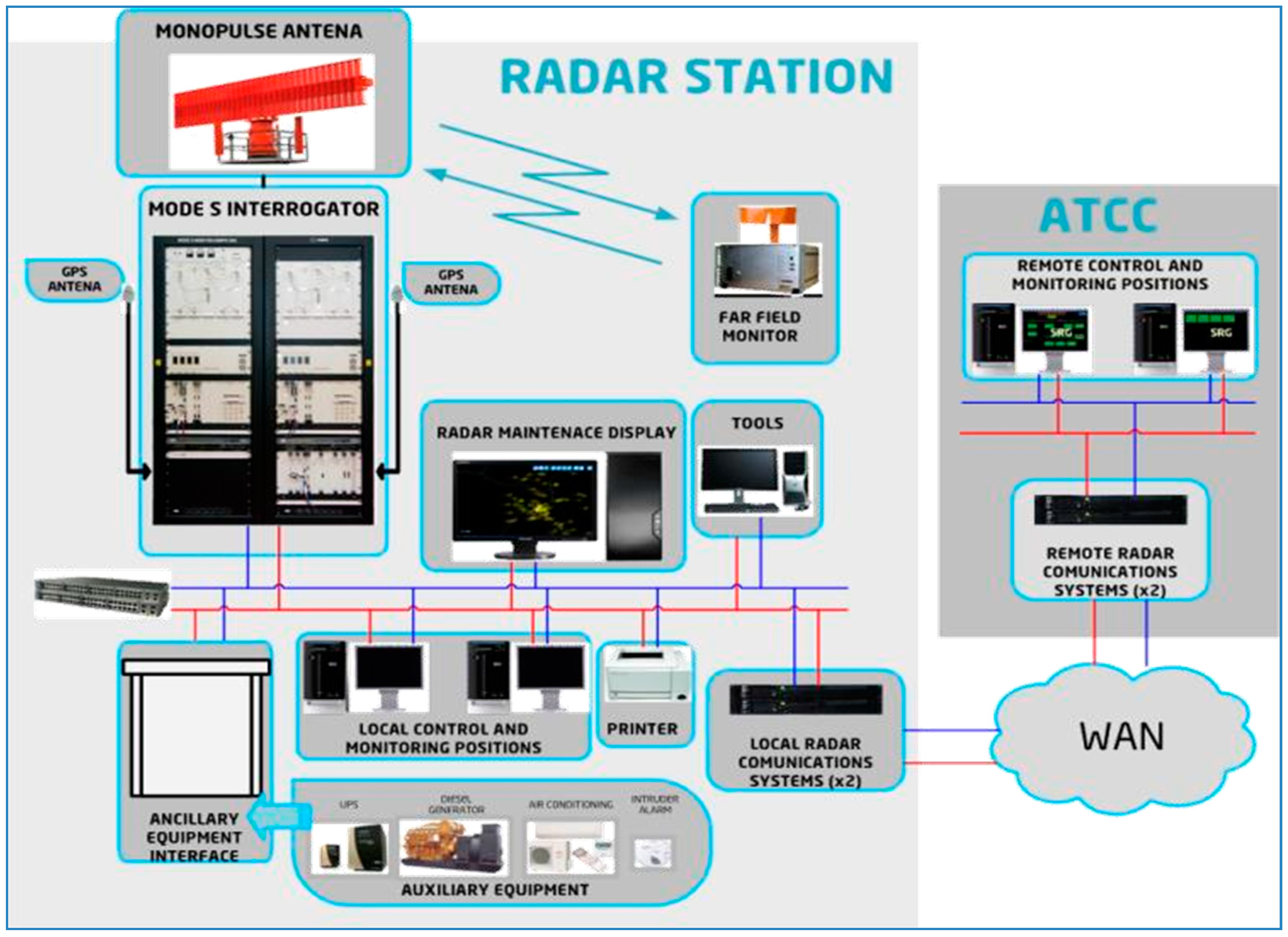
2.5. Diagram of the Transportable Radar
3. Methods
3.1. Sprint N° 1
3.2. Sprint N° 2
3.3. Sprint N° 3
4. Result
5. Discussion
6. Conclusions
- The implementation of the MSSR-S transportable radar for Peruvian aeronautical surveillance aims to minimize the operational impact of air traffic, and improve detection, tracking and operational safety features using the SCRUM framework.
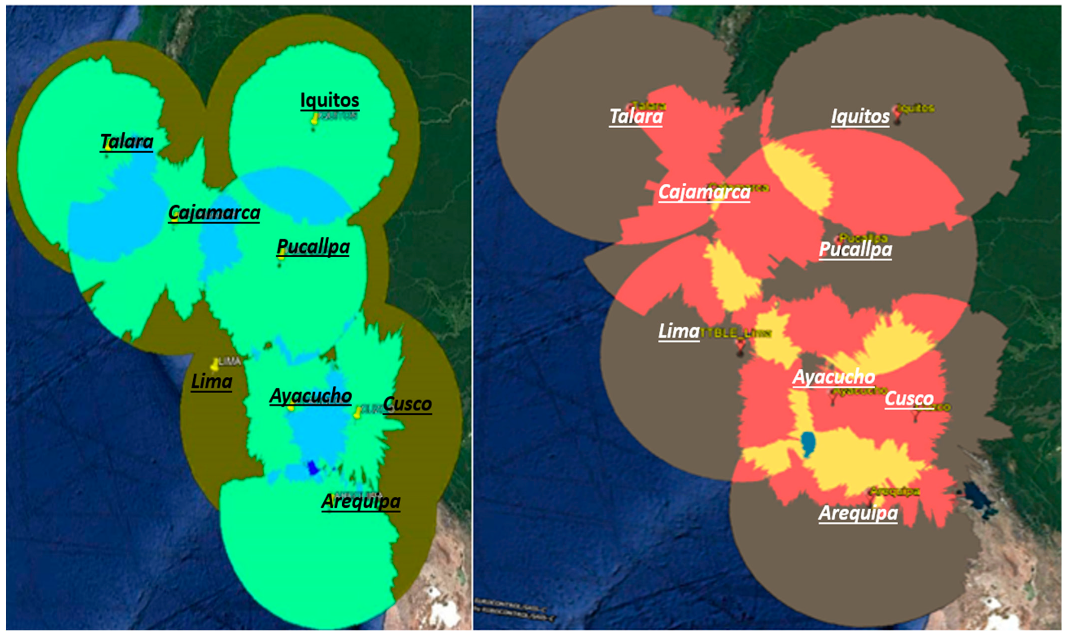
- As shown in Figure 14, the coverage of the transportable radar and the radar from Lima are very similar up to 150 NM (there is an instrument limitation of 150 nautical, iles for the transportable radar). Starting at 150 NM and flight level 100, the radar from Lima has more coverage over some airways in the lower airspace than the transportable radar.This gap in the coverage of the transportable radar is covered from flight-level 250 by the radars from Cajamarca in the north (airway G675), and the radars from Ayacucho and Arequipa in the south (airways L525 and L302). In both the Lima TMA and the Pisco TMA, both radars have the same radar coverage.
- Surveillance systems continue to constantly evolve with the use of new technologies, continuously improving the detection techniques and data communications, leading to a surveillance system characterized by its optimum coverage, maximum reliability and high availability, the high quality of the information provided, and the minimal cost of exploration.
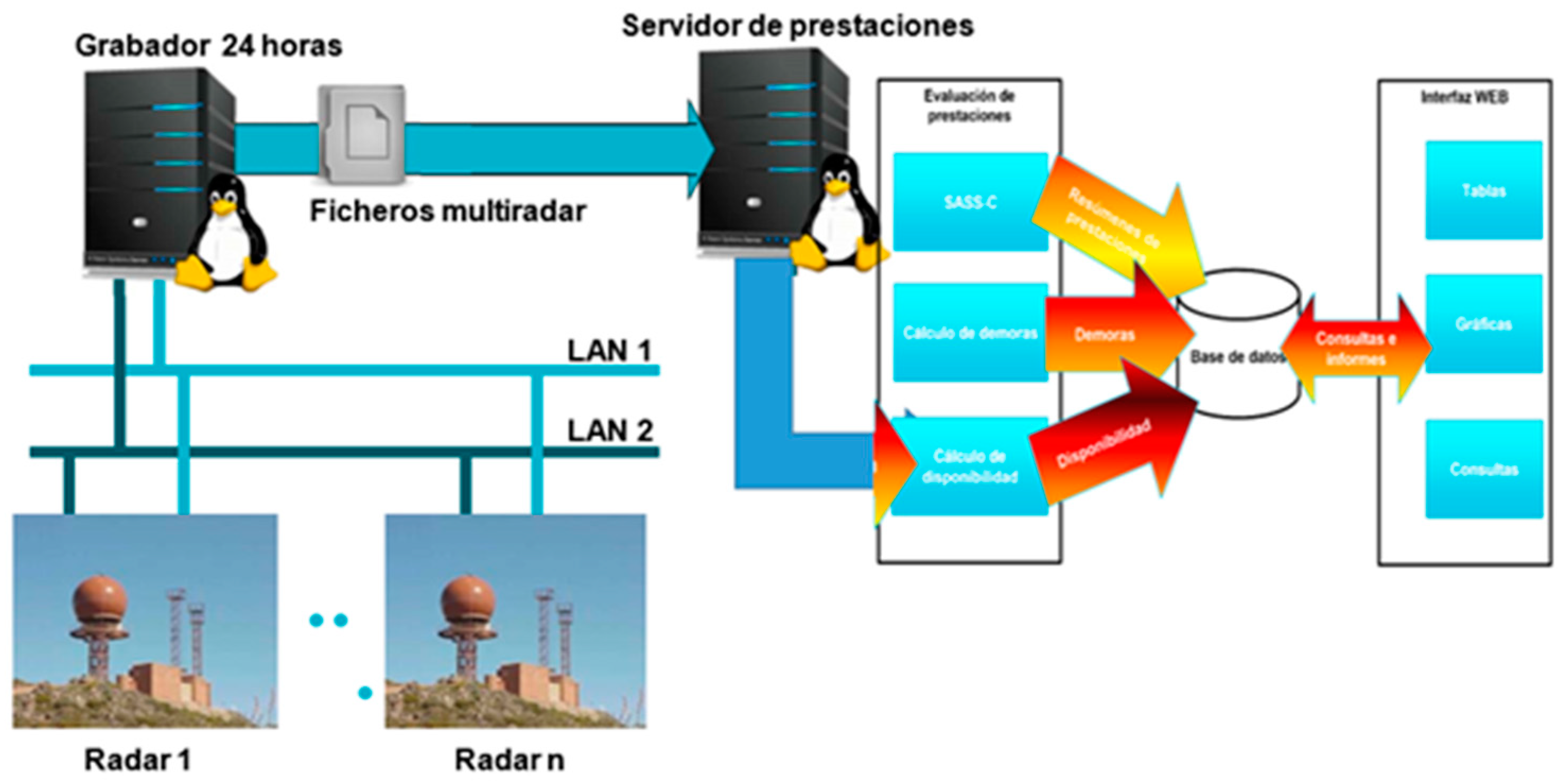
- The information obtained from aircrafts by surveillance sensors can be essential and elementary (position, altitude and identification), or can involve more elaborate data communications (enhanced surveillance), in all phases of flight and on the ground. A continuous analysis of surveillance sensors is performed to meet the requirements established by ICAO for air surveillance systems. The eight radars, which are part of the surveillance system from CORPAC, are very good in terms of both position and detection. This is achieved through the PASS application.
- The preventive and corrective maintenance carried out by the radar sites has been optimized, minimizing the operational impact and covering the airspace while the radar is out of operation, as shown in the analysis of the results.
Author Contributions
Funding
Data Availability Statement
Conflicts of Interest
References
- Andrés Mauricio, B.C. Implementation of a Mobile Radar System Using a Doppler Sensor for the obstacle Detection. Bachelor’s Thesis, Universidad de los Llanos, Villavicencio, Meta, Colombia, 2019. [Google Scholar]
- Minteuan, G.; Palade, T.; Puschita, E.; Dolea, P.; Pastrav, A. Monopulse Secondary Surveillance Radar Coverage—Determinant Factors. 2021. Available online: https://www.mdpi.com/1424-8220/21/12/4198/htm (accessed on 13 March 2023).
- Gonzáles, P.N. Implementation of Algorithms in Secondary Radar for Tracking Targets on Mobile Platforms. 2016. Available online: https://oa.upm.es/44168/3/TFG_PABLO_NIETO_GONZALEZ.pdf (accessed on 10 June 2023).
- ICAO. Fifth Meeting of the Working Group on Air Navigation Implementation for the NAM/CAR Regions. 2019. Available online: https://www.icao.int/NACC/Documents/RegionalGroups/ANIWG/ANIWG05 (accessed on 21 July 2023).
- ICAO. Guide of the Global Surveillance [PDF Version] (THALES AIR SYSTEMS ed.) 2021. Available online: https://www.icao.int/NACC/Documents/Meetings/2021/ADSB1 (accessed on 5 May 2023).
- INDRA. Radar Monopulse Mode S System. 2019. Available online: https://www.indracompany.com (accessed on 20 April 2023).
- Guo, J.; Tao, H. Cramer-Rao Lower Bounds of Target Positioning Estimate in Netted Radar System. 2021. Available online: https://www.sciencedirect.com/science/article/abs/pii/S105120042100261X (accessed on 6 June 2023).
- Prasetya, K.D.; Pratama, D. Effectiveness Analysis of Distributed Scrum Model Compared to Waterfall Approach in Third-Party Application Development. 2021. Available online: https://www.sciencedirect.com/science/article/pii/S1877050920324558?via%3Dihub (accessed on 18 April 2023).
- Vismari, L.F.; Junior, J.B.C. A Safety Assessment Methodology Applied to CNS/ATM-Based Air Traffic Control System. 2011. Available online: https://www.sciencedirect.com/science/article/abs/pii/S095183201100024X (accessed on 12 December 2022).
- Martínez Pastor, A.J. Design of a Radar Presentation for Mobile Devices in Android. Bachelor’s Thesis, Universitat Politècnica de València, València, Spain, 2021. [Google Scholar]
- Žáčik, N.; Novák, A.; Soto, A.; Drupka, G. SASS-C Processing Capability of MSPSR Data. 2018. Available online: https://www.sciencedirect.com/science/article/pii/S2352146517310918 (accessed on 7 January 2023).
- Santiago, A.R.G. System for Tracking and Generating Tracks for Radar Track While Scan. Master’s Thesis, National University of Córdoba, Córdoba, Argentina, 2019. [Google Scholar]
- Capotosti, S.; Scacco, M.; Nelli, L.; DellÓmo, D.; Panuccio, M. Hypatia-trackRadar: A Software for Animal Tracking Using Marine Surveillance Radars 2019. Available online: https://www.sciencedirect.com/science/article/abs/pii/S1574954118302097 (accessed on 5 April 2023).
- Gil, S. Analysis and simulation of surface radar at X-band airports, development of modifications to optimize detection capacity. Available online: https://oa.upm.es/57851/ (accessed on 8 January 2023).


| Phase | Activities | Objectives |
|---|---|---|
| Implementation preparatory |
|
|
| Site Analysis |
|
|
| On-site Implementation |
|
|
| Transportable Radar Deployment |
|
|
| Integration of transportable radar |
|
|
| System in service and performance analysis |
|
|
| Coverage radar | Scope: 256 NM. 66,000 ft altitude. |
| Probability of detection (Pd) | SSR: 397%. Mode S: 399%. |
| Probability of code validation | Mode: 3/A: ≥98%. Mode C: ≥96%. Mode S: ≥99%. |
| Detection of code | Mode: 3/A, C. Codes: 7500, 7600, 7700. Train of repetition from army emergency. Train of repetition from army identity. Detection and correction from mistakes for reply in S. |
| Validated false codes | Mode: 3/A: <0.1%. Mode C: <0.1%. |
| False blanks | <0.1% lower to sweep like a medium. |
| Validated dates from false repetition Comm-B or Comm-D | No more than 1 segment in 107 messages. |
| Multiple blank process | Capacity for discrimination. |
| Asincrone environment support (fruit environment supported) | ≥11,000 asincrones/seconds in the main haz from anthens. |
| Scope precision (systematic mistakes) | ≤14 m. |
| Scope precision (aleatory mistakes) | Mode S: 10 ≤ 15 mt. SSR: 10 ≤ 30 mt. |
| Acimut precision (systematic mistakes) | 0 < OD < 6° < 6°:0.022°. 6 <OD < 10°: £0.033°. |
| Acimut precision (aleatory mistakes) | Scope: ≤1/128 NM. Acimut: ≤0.022°. |
| Global rate from jumps | <0.05%. |
| PROCESS FROM NEXT BLANKS (GARBLING) | |
| N° soften overlaping reply | Four SST, rejected from the ghost. Two-mode S. |
| Probability of detection of two blanks SSR | ≤60% ( < 0.05 NM, scope, <0.6° acimut). ≤98% (0.5 a <2 NM; scope, ≤0.6° acimut). ≤98% (2 NM; scope, >0.6° y < 48 acimut). |
| Radar | Number of Evaluations | PD <90% | 90% ≤ PD < 95% | 95% ≤ PD < 97% | 97% ≤ PD < 99% | PD ≥ 99% |
|---|---|---|---|---|---|---|
| Arequipa | 120 | 0.83% | 0.83% | 0.00% | 29.17% | 69.17% |
| Ayacucho | 120 | 0.00% | 0.00% | 0.00% | 0.83% | 99.17% |
| Cajamarca | 120 | 0.00% | 0.00% | 0.00% | 0.83% | 99.17% |
| Cuzco | 120 | 0.83% | 0.83% | 0.83% | 7.50% | 90.00% |
| Iquitos | 120 | 0.83% | 3.33% | 12.50% | 38.33% | 45.00% |
| Ttble Lima | 120 | 0.00% | 0.00% | 0.00% | 0.83% | 99.17% |
| Pucallpa | 120 | 0.00% | 0.83% | 0.00% | 35.00% | 64.17% |
| Talara | 120 | 1.67% | 0.00% | 0.83% | 33.33% | 64.17% |
| Radar | Systematic Error Distance | Correct | Systematic Azimuth | Correct |
|---|---|---|---|---|
| Arequipa | 51.89 m | NO | 0.0139° | NO |
| Ayacucho | 6.34 m | NO | 0.0152° | NO |
| Cajamarca | −47.21 m | NO | 0.0126° | NO |
| Cuzco | 72.14 m | NO | −0.0198° | NO |
| Iquitos | −50.70 m | NO | 0.0122° | NO |
| Ttble Lima | −3.80 m | NO | 0.0127° | NO |
| Pucallpa | 21.67 m | NO | −0.0002° | NO |
| Talara | 27.81, | NO | 0.0059° | NO |
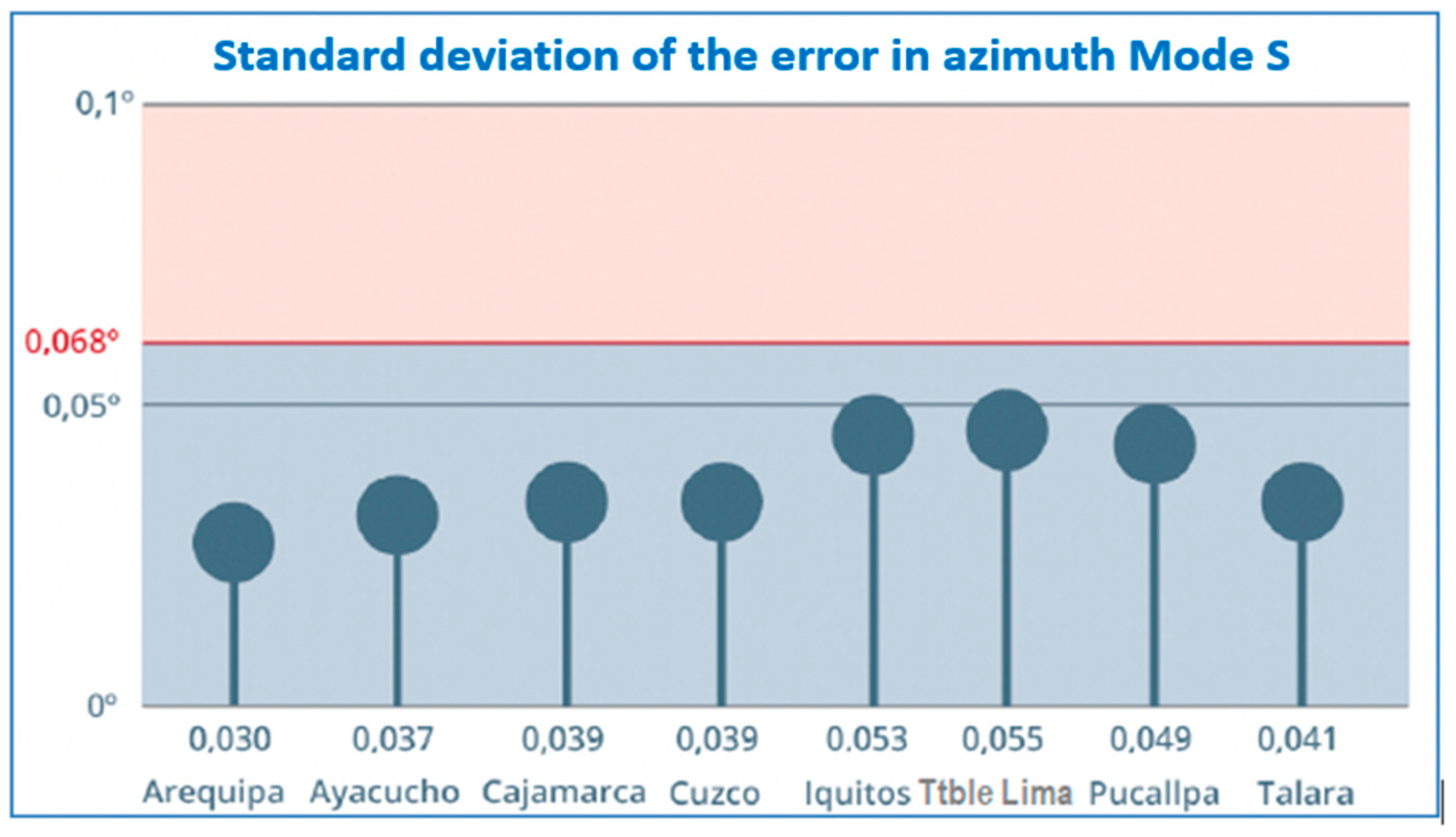
| Radar | Number of Evaluations | STD Error Acimut | % Evaluations STD > 0.068° | State |
|---|---|---|---|---|
| Arequipa | 120 | 0.0289° | 1.67% | Correcto |
| Ayacucho | 120 | 0.0389° | 5.83% | Correcto |
| Cajamarca | 120 | 0.0423° | 5.00% | Correcto |
| Cuzco | 120 | 0.0367° | 5.00% | Correcto |
| Iquitos | 120 | 0.0545° | 20.00% | Correcto |
| Ttble Lima | 120 | 0.0544° | 7.50% | Correcto |
| Pucallpa | 120 | 0.0469° | 1.67% | Correcto |
| Talara | 120 | 0.0442° | 4.17% | Correcto |
Disclaimer/Publisher’s Note: The statements, opinions and data contained in all publications are solely those of the individual author(s) and contributor(s) and not of MDPI and/or the editor(s). MDPI and/or the editor(s) disclaim responsibility for any injury to people or property resulting from any ideas, methods, instructions or products referred to in the content. |
© 2023 by the authors. Licensee MDPI, Basel, Switzerland. This article is an open access article distributed under the terms and conditions of the Creative Commons Attribution (CC BY) license (https://creativecommons.org/licenses/by/4.0/).
Share and Cite
Vidal, L.E.; Concha, U.R.; Solís, J.; Piedra, J.; Chávez, C.; Cano, D.M.; Woolcott, J.C. Implementation of a Transportable Radar Mode S of Monopulse Secondary Surveillance (MSSR-S) for the Peruvian Civil Aviation Surveillance. Telecom 2023, 4, 693-708. https://doi.org/10.3390/telecom4040031
Vidal LE, Concha UR, Solís J, Piedra J, Chávez C, Cano DM, Woolcott JC. Implementation of a Transportable Radar Mode S of Monopulse Secondary Surveillance (MSSR-S) for the Peruvian Civil Aviation Surveillance. Telecom. 2023; 4(4):693-708. https://doi.org/10.3390/telecom4040031
Chicago/Turabian StyleVidal, Luis. E., Ulises Román Concha, Justo Solís, José Piedra, Carlos Chávez, Dominga M. Cano, and Juan C. Woolcott. 2023. "Implementation of a Transportable Radar Mode S of Monopulse Secondary Surveillance (MSSR-S) for the Peruvian Civil Aviation Surveillance" Telecom 4, no. 4: 693-708. https://doi.org/10.3390/telecom4040031