
The Static and Dynamic Behavior of Steel Storage Tanks over Different Types of Clay Soil


1
Structural Engineering Department, Zagazig University, Zagazig 44519, Egypt
2
Department of Engineering and Technology, Texas A&M University-Commerce, Commerce, TX 75429, USA
*
Author to whom correspondence should be addressed.
CivilEng 2023, 4(4), 1169-1181; https://doi.org/10.3390/civileng4040064
Submission received: 19 August 2023
/
Revised: 11 November 2023
/
Accepted: 20 November 2023
/
Published: 22 November 2023
(This article belongs to the Special Issue Feature Papers in CivilEng)
Abstract
:Steel storage tanks are widely used in different fields. Most of these tanks contain hazardous materials, which may lead to disasters and environmental damage for any design errors. There are many reasons which cause the failure of these tanks such as excessive base plate settlement, shear failure of soil, liquid sloshing, and buckling of the tank shell. In this study, five models of above-ground steel storage tanks resting over different types of clay soils (medium-stiff clay, stiff clay, and very stiff clay soils) are analyzed using the finite element program ADINA under the effect of static and dynamic loading. The soil underneath the tank is truly simulated using a 3D solid (porous media) element and the used material model is the Cam-clay soil model. The fluid in the tank is modeled depending on the Navier–Stokes fluid equation. Moreover, the earthquake record used in this analysis is the horizontal component of the Loma Prieta Earthquake. The analyzed tanks are circular steel tanks with the same height (10 m) and different diameters (ranging from 15 m to 40 m). The soil under the tanks has a noticeable effect on the dynamic behavior of the studied tanks. The tanks resting over the medium-stiff clay (the weakest soil) give a lower permanent settlement after the earthquake because of its low elastic modulus which leads to the absorption of the earthquake waves in comparison to the other types of soil. There are 29.6% and 35.6% increases in the peak dynamic stresses under the tanks in the cases of stiff clay and very stiff clay soils, respectively. The maximum values of the dynamic vertical stresses occur at a time around 13.02 s, which is close to the peak ground acceleration of the earthquake.
Keywords:
steel tanks; settlement; vertical stress; stiff clay; axial compression stress; earthquake1. Introduction
The cylindrical steel storage tanks are essential for many industries to store chemical and petroleum materials. Studying the behavior of these tanks under static and dynamic loads is essential because any accident may lead to human or environmental damage. Most popular failures occur due to foundation settlement, shell buckling, anchorage system, and sloshing of liquid from the tank. There are two types of foundation settlement (uniform settlement and differential settlement) under these types of tanks. The uniform settlement always leads to serviceability failure. However, the differential settlement can cause failure in the tank body [1,2]. Ground motion during an earthquake varies in its magnitude, direction, and position with time. This motion causes the structure to vibrate or shake in all directions. Therefore, it is necessary to ensure that the structure can resist horizontal earthquake shaking. In most structural engineering calculations, dead loads, live loads, and wind loads can be evaluated with a fair degree of accuracy. However, the situation with regard to earthquake forces is entirely different. Earthquake loads are inertia forces whose magnitude is a function of mass, stiffness, and energy-absorbing capacity (e.g., damping and ductility of elements). Earthquake response also depends on the overall geometry of the structure. Several dynamic analysis methods are available to analyze the behavior of structures such as the Response Spectrum Method and Time History Method [3].
The dynamic behavior of steel and concrete storage tanks has been studied theoretically and experimentally by many scientists. A wide range of studies on the dynamic response of storage tanks began in the late 1940s. Jacobsen [4] calculated the effective hydrodynamic masses and mass moments for the fluid inside a cylindrical tank under the horizontal translation of the tank base. The finite element method was used to study the seismic behavior of flexible tanks where the hydrodynamic effects of liquid were taken into consideration as an added mass matrix in the equation of motion of the coupled fluid-tank system [5]. Sanchez et al. [6] studied numerically the behavior of existing steel storage tanks under seismic conditions in high-risk zones using the time history analysis method. The fluid–structure interaction was taken into consideration in order to estimate the dynamic pressure distribution of the fluid. Konstandakopoulou and Hatzigeorgiou [7] focused on the quantification of the dynamic sequence influence in studied tanks. The study counted the actual dynamic sequences that had been documented throughout a small period of time (up to three days for tracking the earthquake aftershocks). It was untrustworthy to deem only a single earthquake results in designing steel tanks because the behavior of tanks differs from one earthquake to another. Spritzer and Guzey [8] studied the behavior of eight aboveground steel oil storage cylindrical tanks under seismic excitations using ABAQUS software. A series of elastic springs were used to model the soil domain under the tank. It was assumed that the tank was resting on stiff clay soil. The hydrodynamic hoop stresses, elephant foot buckling, and uplift were obtained for tanks with different height-to-radius ratios. Hosseinzadeh et al. [9] studied numerically the dynamic response of steel storage liquid tanks and compared the numerical results with those of the API procedures [10]. Results showed that both the impulsive and convective modal periods (Ti and Tc) obtained from [10] were similar to the results obtained from the numerical analyses. Moreover, the numerical analysis obtained good agreement with [10] in determining the location of maximum hoop stresses which lead to elephant-foot buckling and estimating the total hoop stresses. Hamdan [11] evaluated the accuracy of current design strategies with special emphasis on EUROCODE 8 (EC8), part 4 [12]. A significant goal of this research was to study several phenomena such as sloshing, required freeboard, base shear, overturning moment, and buckling strength because current design procedures need further improvement. The maximum sloshing height achieved from the three-dimensional numerical analysis was found to lie in the range of the code procedures for unanchored tanks. However, it was larger than those expected by ref. [12] for the same anchored tank. The elephant-foot buckling resistance of three steel tanks with variant geometries was analyzed using finite element dynamic analysis [13]. Critical rates of the peak ground acceleration which ran to buckling damage of these tanks were estimated. All the studied tanks showed the same elastoplastic buckling behavior under seismic motions. Increasing the aspect ratio (H/D) of the studied tanks led to an increase in the risk of elephant-foot buckling. Moreover, elephant-foot buckling was found to occur at high peak ground acceleration values for low aspect ratio tanks; however, it happened at lower peak ground acceleration values for high aspect ratio tanks.
The soil–structure interaction showed an appreciable impact on the predicted displacements under the concrete surge tank resting on relatively rigid soil. These displacements tended to increase when the soil deformability was considered [14]. Minoglou et al. [15] developed a simplified, fast, and direct optimum seismic design of steel tanks, avoiding complicated computational methods. The optimum seismic design of these tanks was achieved by satisfying the stability of these structures under extreme seismic design loads. Hjorteset et al. [16] discussed the unique design and construction challenges encountered in the development of large-scale precast concrete cryogenic storage tanks, along with special considerations necessary when fabricating, handling, erecting, temporarily supporting, integrating, and post-tensioning long and slender precast concrete wall elements.
There are many codes that introduce procedures to analyze and design above-ground steel storage tanks such as the API [10]. However, accidents still occur. These codes depend on the response spectrum analysis to design these tanks in the dynamic stage and they don’t take into consideration the soil–structure interaction. Therefore, this research is interesting in studying steel storage tanks using time history analysis and taking into consideration the soil–structure interaction. Five models of above-ground steel storage tanks resting over different types of clay soils (medium-stiff clay, stiff clay, and very stiff clay soils) are analyzed using the finite element program ADINA [17] under the effect of static and dynamic loading. The soil underneath the tank is truly simulated using a 3D solid (porous media) element and the used material model is the Cam-clay soil model. The fluid in the tank is modeled depending on the Navier–Stokes fluid equation. Moreover, the earthquake record used in this analysis is the horizontal component of the Loma Prieta Earthquake. The analyzed tanks are circular steel tanks with the same height (10 m) and different diameters (ranging from 15 m to 40 m). Although elephant foot buckling is one of the most common types of failure in these steel tanks, it is out of the scope of this research. This research focuses mainly on soil–structure interaction and the static and dynamic effect of different soil types on circular steel tanks.
2. FE Modeling
In this part, unanchored above-ground steel storage tanks are studied using the finite element program ADINA (System 9.6.0, ADINA R&D, Inc., Watertown, MA, USA) [17]. In general, the whole steel tank and the underlying soils and foundation elements (50 cm embedded reinforced concrete foundation) are modeled in 3D, as shown in Figure 1. The main advantage of this study is that the soil underneath the tank is truly simulated using a 3D solid (porous media) element, and the used material model is the Cam-clay soil model. However, most previous research simulates the soil underneath the tank as spring supports.
ADINA FSI offers comprehensive capabilities for solving problems involving the interaction between general nonlinear structures and general Navier–Stokes or Reynolds fluid flow all tightly integrated in a single program (one model). In addition, the Direct FSI Coupling solution method was used where the fluid and solid equations are combined and treated in one system (one stiffness matrix), linearized, and solved using an iterative algorithm (the Newton–Raphson method) [14].
2.1. Elements
The steel tank walls are represented by elastic isotropic shell elements, which are also used to model the tank bottom plate and reinforced concrete foundation. Moreover, the fluid inside the tank is modeled by a 3D fluid linear potential-based element with a free surface with the capability to consider fluid–structure interaction under the applied acceleration. The fluid in the tank is modeled depending on the Navier–Stokes fluid equation. The equation is a generalization of the equation devised by the Swiss mathematician Leonhard Euler in the 18th century to describe the flow of incompressible and frictionless fluids.
2.2. Boundary Conditions
For static analysis, the side boundary of the soil is considered to be roller support to allow soil settlement. However, the lower boundary is taken to be hinged support to prevent horizontal and vertical movements, as shown in Figure 1. During the seismic loading, rollers in the side boundaries are removed, and the right and left corresponding finite element nodes are set to primary and secondary, forcing the nodes on the left side of the mesh to act exactly as the similar node in the right boundary of the mesh. In such conditions, the whole soil domain will act as a gel with each node on one side to be tied to a similar node on the other side. The incident earthquake waves in such cases will not be reflected back into the soil domain because there are no rigid side boundaries. This technique is widely applied in soil dynamics applications, among them [18,19]. Moreover, the hinge supports at the lower boundary of the model are switched to roller supports to allow horizontal movement due to the earthquake. ADINA software allows modeling the pore pressure on the soil volume and auto-assigns its boundary conditions based on the boundary conditions of the soil. The earthquake horizontal component acceleration-time history is applied at the bottom of the soil domain inducing the effect of the earthquake motion in that domain. The horizontal component of an earthquake has the greatest impact on the structures [20]. Therefore, the horizontal component of the Loma Prieta Earthquake accelerations is considered in this research.
The size of the soil domain is presented in Figure 2. Many trials are performed using different dimensions of the soil media to reach the minimum media size which does not affect the accuracy of the results. These trials are carried out to attain the maximum element size which does not affect the results in order to reduce the time of solution.
2.3. Materials
The tank shell and reinforced concrete foundation are represented by elastic isotropic shell elements. The linear elastic-isotropic material model is available for the 3D solid elements. Three parameters are used to define the elastic-isotropic material. These parameters are Young’s modulus (E), Poisson’s ratio (v), and density (ρ). The base and shell materials are taken according to ASTM A516 [21] to be steel with Grade 70. Moreover, the fluid inside the tank is modeled by a 3D fluid linear potential-based element with a free surface as Navier–Stokes fluid with the capability to consider the fluid–structure interaction under the applied acceleration. The specific gravity of the liquid (oil) inside the tank is equal to 0.9.
The soil is simulated using the Cam-clay soil model. Six parameters are needed to define the model. These parameters are the initial void ratio (eo), the Poisson’s ratio (Ʋ), the unloading–reloading index (ĸ), the compression index (λ), the isotropic pre-consolidation pressure (Po), and the friction angle (Ø’). The first five parameters express the soil stiffness and the sixth parameter is used to predict the shear strength [22,23]. Modeling of the soil nonlinear behavior using the Cam-clay model in ADINA requires the main five parameters, as input for the Cam-clay model. Other intrinsic parameters are also needed in modeling, such as the modulus of elasticity, bulk density, and Poisson’s ratio [17]. The properties of clay soils, steel, and concrete materials used in this research are listed in Table 1.
The element birth and death feature is useful for modeling processes during which material is added to and/or removed from the structure. In this research, the birth and death option is used. The stiff clay soil is born at time = 0 s (at the beginning of the model) and after that, the foundation (steel plate) is born, then the tank shell and the fluid are also born, respectively.
2.4. Procedures of the FE Analysis
The static and dynamic analyses are conducted to analyze the performance of the various tank models resting over different clay soils. Firstly, the static analysis is carried out which includes defining and modeling the tank, soil, foundation, and liquid and applying the boundary conditions. The total settlement, differential settlement, and stresses in soil are calculated after this stage of analysis. Secondly, the dynamic analysis is performed, which includes applying the seismic loads at the lower soil domain boundary to account for a striking earthquake event as an acceleration-time history. The earthquake record used in this analysis is the horizontal component of the Loma Prieta Earthquake [24], as shown in Figure 3.
2.5. Details of the Studied Tanks
Five models of circular steel tanks with the same height (10 m) and different diameters (ranging from 15 m to 40 m) are considered in this study, as listed in Table 2. These dimensions are chosen according to their prevalence in the industry. Figure 2 shows the FE model of the above-ground open-top oil storage steel tank resting on extended stiff clay soil.
3. Results of the Static Analysis
3.1. The Consolidation Settlement under the Base Plate of the Tank
Consolidation settlement of clay soil is a very significant factor in studying structures resting over such soil. In this paper, the static loads that cause consolidation settlement are the tank shell, tank base plate, and oil inside the tank. Local codes give limits to the total and differential settlements. The Egyptian Code [25] gives a limit of the total settlement of a raft resting on clay soil not exceeding 15 cm. The relationship between the tank diameter and the maximum settlement in different clay soils is presented in Figure 4. It is noticed that the settlement increases with the increase in the tank diameter for all cases of different types of clay. Increasing the tank diameter from 15 m to 40 m causes an increase in the total settlement from 9.72 cm to 15.60 cm for the case of medium-stiff clay. This represents a 60% increase in the total settlement. However, increasing the tank diameter from 15 m to 40 m causes only an increase in the total settlement by 44% and 40% for the cases of stiff clay and very stiff clay soils, respectively. Figure 5 shows the color contour shading of the settlement under the tank for the stiff clay soil case. It is clear from these results that the maximum value of the settlement occurs under the tank foundation directly and whenever the soil depth under the tank goes down, the settlement decreases.
3.2. The Vertical Stress within the Soil Media
The vertical stress in the soil domain is mainly induced by the weight of its solid particles, water, and any structure constructed above the soil. It is very important to estimate this kind of stress because of its effect on the behavior of structures constructed over that soil. Figure 6 presents the color contour shading of stress ZZ (overburden pressure + weights of tank and fluid) for the tank in the case of medium-stiff clay. As seen from these results, the pressure increases just under the tank because of the additional stress that comes from the tank and fluid weights.
The relation between the additional stress due to the tank and fluid weights (∆σ) and the ratio between the depth under the tank and the tank diameter (d/B) in the case of stiff clay is presented in Figure 7. It is found that the values of the additional stress under the tank base (at d/B = 0) are 79,850, 84,600, 83,700, 81,700, and 83,200 N/m2 for the analyzed cases (see Table 2). However, these values decrease gradually whenever the depth under the tank goes down for all cases. At d/B = 1.5, the additional stresses reach 15,115, 15,650.5, 13,742.2, 11,275, and 10,693.6 N/m2 for the analyzed cases. These values are only about 18.9%, 18.5%, 16.4%, 13.8%, and 12.8% of the stress values under the tank base. These results confirm the empirical results that consider 15% of the stress can be reached at a depth of 1.5 of the footing width [25].
4. Results of the Dynamic Analysis
The following dynamic results were extracted from the influence of one earthquake (Loma Prieta) records on the steel storage tanks over different types of clay soil.
4.1. The Settlement under the Tank Base Plate
During earthquakes, settlement under the structures varies which may lead to structure or serviceability damages. Therefore, studying settlement under steel storage tanks due to the Loma Prieta earthquake is presented in this section. Figure 8 shows the relationships between the tank diameter and the excess settlement under the tank after the earthquake for all studied cases. It is found that decreasing the tank diameter leads to an increase in the settlement. The excess settlement increases from 0 to 8.5 mm, from 3.4 to 17 mm, and from 9.9 to 22 mm for the tanks rest over medium-stiff clay, stiff clay, and very stiff clay, respectively, when the tank diameter decreases from 40 to 15 m. It is also noticed that the soil under the tanks has a noticeable effect on the behavior of the studied tanks. The tanks resting over the medium-stiff clay (the weakest soil) give a lower permanent settlement after the earthquake because of its low elastic modulus which leads to the absorption of the earthquake waves in comparison to the other types of soil. Therefore, the tanks with high diameters experience the lowest values of settlements after the dynamic excitations. Figure 9 presents the settlement time history of tank 5 in the cases of medium-stiff clay and very stiff clay. It is noticed that there is a noticeable sudden settlement at 13.30 s (close to the peak ground acceleration of the earthquake) for both cases where the maximum settlement reaches 44 mm and 32 mm for the two cases, respectively. On the other hand, the settlement oscillates around 8.5 mm and 22 mm for the tank resting over medium-stiff clay and very stiff clay, respectively.
4.2. The Vertical Stresses within the Soil Media
The vertical stresses within the soil media vary during the earthquake excitations. Therefore, it is important to study the vertical stresses during the earthquake to detect the maximum values of these stresses and the corresponding times at which they occur. Figure 10 shows the variation in the vertical stresses with time at a critical point located under the corner of the base plate of tank 4 for the cases of medium-stiff clay, stiff clay, and very stiff clay soils. The maximum values of the dynamic vertical stresses are 583, 755.8, and 791 kPa for the cases of medium-stiff clay, stiff clay, and very stiff clay soils, respectively, and occur at a time around 13.02 s, which is close to the peak ground acceleration of the earthquake. There are 29.6% and 35.6% increases in the peak stresses in the cases of stiff clay and very stiff clay soils, respectively. The lower elastic modulus value of the medium-stiff clay soil, in comparison to the other types, leads to the absorption of earthquake waves and, subsequently, relief of the vertical stress values.
Figure 11 presents the relationship between the tank diameter and the vertical dynamic stress for the cases of medium-stiff clay, stiff clay, and very stiff clay soils. For tank 1 with a diameter of 40 m, the vertical dynamic stress increases from 230 kPa to 442 kPa (by 92.1%) when the medium-stiff clay soil is replaced with the very stiff clay soil. The results in Figure 11 confirm that decreasing the tank diameter from 40 m to 20 m causes reductions in the vertical dynamic stresses under the tank by 60.5%, 47.8%, and 44.1% for the medium-stiff clay, stiff clay, and very stiff clay soils, respectively. On the other hand, decreasing the tank diameter from 20 m to 15 m has no noticeable effect on the vertical dynamic stress for all the studied cases. Moreover, the tanks resting over the medium-stiff clay soil (weakest soil) show the minimum values of these stresses during the earthquake.
4.3. The Axial Compressive Stresses in the Tank Shells
Studying the axial compression stresses in the tank shells is extremely important because it may cause failure in the tank shell (buckling failure). Therefore, the maximum longitudinal shell-membrane compression stresses are investigated for all the studied cases (medium-stiff clay, stiff clay, and very stiff clay soils). It is found that the maximum axial compression stress in the tank shell occurs at the lower boundary of the tank. Figure 12 presents the relationship between the tank diameter and the maximum axial dynamic compression stress in the tank shell. The results show that the tanks resting over medium-stiff clay soil (weakest soil) show the minimum values of the axial compression stresses because of the low elastic modulus of this soil which leads to the absorption of the earthquake waves in comparison to the other types of soils. Moreover, decreasing the tank diameter from 40 m to 15 m causes significant increases in the axial compression stress by 265%, 186%, and 172% for the tanks resting over medium-stiff clay, stiff clay, and very stiff clay soils, respectively.
Figure 13 shows the variation of axial compression stress with time at a critical point located under the corner of the tank shell (tank 3) for the cases of medium-stiff clay, stiff clay, and very stiff clay soils. The values of maximum axial compression stresses are 6.3, 7.7, and 7.6 MPa for all studied cases, respectively, and occur at a time around 13.0 s (close to the peak ground acceleration of the earthquake).
5. Conclusions
In this study, five models of above-ground steel storage tanks resting over different types of clay soils (medium-stiff clay, stiff clay, and very stiff clay soils) are analyzed using the finite element program ADINA under the effect of static and dynamic loading (Loma Prieta earthquake only). The soil underneath the tank is truly simulated using a 3D solid (porous media) element and the used material model is the Cam-clay soil model. The fluid in the tank is modeled depending on the Navier–Stokes fluid equation. Moreover, the earthquake record used in this analysis is the horizontal component of the Loma Prieta Earthquake. The analyzed tanks are circular steel tanks with the same height and different diameters. The numerical results could lead to the following conclusions:
- The settlement under static loading increases with increasing the tank diameter for all cases of different types of clay. Increasing the tank diameter from 15 m to 40 m causes a 60% increase in the total settlement for the case of medium-stiff clay. However, the increases are 44% and 40% for the cases of stiff clay and very stiff clay soils, respectively.
- The vertical static stresses just under the tank are the maximum because of the additional stress that comes from the tank and fluid weights. However, these values decrease gradually (about 18.9%, 18.5%, 16.4%, 13.8%, and 12.8% of the stress values under the tank base) whenever the soil depth under the tank goes down for all cases. These results confirm the empirical results that consider 15% of the stress can be reached at a depth of 1.5 of the footing width.
- The soil under the tanks has a noticeable effect on the dynamic behavior of the studied tanks. The tanks resting over the medium-stiff clay (the weakest soil) give a lower permanent settlement after the earthquake because of its low elastic modulus which leads to the absorption of the earthquake waves in comparison to the other types of soil.
- There are 29.6% and 35.6% increases in the peak dynamic stresses under the tanks in the cases of stiff clay and very stiff clay soils, respectively. The maximum values of the dynamic vertical stresses occur at a time around 13.02 s, which is close to the peak ground acceleration of the earthquake.
- The tanks resting over medium-stiff clay soil (weakest soil) show the minimum values of the axial compression stresses in the tank shells because of the low elastic modulus of this soil which leads to the absorption of the earthquake waves in comparison to the other types of soils. Moreover, decreasing the tank diameter from 40 m to 15 m causes significant increases in the axial compression stress by 265%, 186%, and 172% for the tanks resting over medium-stiff clay, stiff clay, and very stiff clay soils, respectively.
Author Contributions
Conceptualization, T.N.S.; Data Curation, A.E.-Z.; Formal Analysis, A.E.-Z. and A.M.A.; Methodology, T.N.S. and A.M.A.; Resources, A.E.-Z. and A.M.A.; Software, A.M.A.; Supervision, T.N.S.; Validation, A.M.A.; Writing—Original Draft, T.N.S. and A.M.A.; Writing—Review and Editing, A.E.-Z. All authors have read and agreed to the published version of the manuscript.
Funding
This research received no external funding.
Data Availability Statement
Data are contained within the article.
Conflicts of Interest
The authors declare no conflict of interest.
References
- Marr, A.W.; Ramos, J.A.; Lambe, W.T. Criteria for settlement of tanks. J. Geotech. Eng. Div. 1982, 108, 1017–1039. [Google Scholar] [CrossRef]
- D’orazio, T.B.; Duncan, J.M. Differential settlements in steel tanks. J. Geotech. Eng. 1987, 113, 967–983. [Google Scholar] [CrossRef]
- Chandrakar, P.; Bokare, P.S. A Review—Comparison between Response Spectrum Method and Time History Method for Dynamic Analysis of Multistoried Building. Int. J. Sci. Res. (IJSR) 2015, 6, 244–247. [Google Scholar]
- Jacobsen, L.S.; Ayre, R.S. Hydrodynamic Experiments with Rigid Cylindrical Tanks Subjected to Transient Motions. Bull. Seismol. Soc. Am. 1951, 41, 313–346. [Google Scholar] [CrossRef]
- Ma, D.C.; Liu, W.K.; Gvildys, J.; Chang, Y.W. Seismic Behavior of Liquid-Filled Shells. Nucl. Eng. Des. 1982, 70, 437–455. [Google Scholar] [CrossRef]
- Sánchez, H.S.; Salas, C.C.; Domínguez, A.M. Structural behavior of liquid filled storage tanks of large capacity placed in seismic zones of high risk in Mexico. In Proceedings of the 13th World Conference on Earthquake Engineering, Vancouver, BC, Canada, 1–6 August 2004. [Google Scholar]
- Konstandakopoulou, F.D.; Hatzigeorgiou, G.D. Water and Wastewater Steel Tanks under Multiple Earthquakes. Soil Dyn. Earthq. Eng. 2017, 100, 445–453. [Google Scholar] [CrossRef]
- Spritzer, J.M.; Guzey, S. Nonlinear Numerical Evaluation of Large Open-Top Aboveground Steel Welded Liquid Storage Tanks Excited by Seismic Loads. Thin-Walled Struct. 2017, 119, 662–676. [Google Scholar] [CrossRef]
- Hosseinzadeh, N.; Kazem, H.; Ghahremannejad, M.; Ahmadi, E.; Kazem, N. Comparison of API650-2008 Provisions with FEM Analyses for Seismic Assessment of Existing Steel Oil Storage Tanks. J. Loss Prev. Process Ind. 2013, 26, 666–675. [Google Scholar] [CrossRef]
- API 650; Welded Tanks for Oil Storage. American Petroleum Institute: Washington, DC, USA, 2014.
- Hamdan, F.H. Seismic Behavior of Cylindrical Steel Liquid Storage Tanks. J. Constr. Steel Res. 2000, 53, 307–333. [Google Scholar] [CrossRef]
- EN 1998-4, Regulation 305/2011, Directive 98/34/EC, Directive 2004/18/EC; Eurocode 8: Design of Structures for Earthquake Resistance—Part 4: Silos, Tanks and Pipelines. The European Union: Maastricht, The Netherlands, 2006.
- Mehretehran, A.M.; Maleki, S. 3D Buckling Assessment of Cylindrical Steel Silos of Uniform Thickness under Seismic Action. Thin-Walled Struct. 2018, 131, 654–667. [Google Scholar] [CrossRef]
- Lupattelli, A.; Kita, A.; Salciarini, D.; Venanzi, I.; Ubertini, F. Effects of the soil–structure interaction and seismic vertical component on the response of a concrete surge tank. Structures 2023, 55, 310–323. [Google Scholar] [CrossRef]
- Minoglou, M.K.; Hatzigeorgiou, G.D.; Papagiannopoulos, G.A. Heuristic optimization of cylindrical thin-walled steel tanks under seismic loads. Thin-Walled Struct. 2013, 64, 50–59. [Google Scholar] [CrossRef]
- Hjorteset, K.; Wernli, M.; LaNier, M.W.; Hoyle, K.A.; Oliver, W.H. Development of large-scale precast, prestressed concrete liquefied natural gas storage tanks. PCI J. 2013, 58, 40–54. [Google Scholar] [CrossRef]
- ADINA R&D, Inc. ADINA System 9.6.0; ADINA R&D, Inc.: Watertown, MA, USA, 2019. [Google Scholar]
- Zienkiewicz, O.C.; Shiomi, T. Dynamic behavior of saturated porous media; the generalized biot formulation and its numerical solution. Int. J. Numer. Anal. Methods Geomech. 1984, 8, 71–96. [Google Scholar] [CrossRef]
- Salem, T.N. Analysis of Offshore Piles. Ph.D. Thesis, Zagazig University, Zagazig, Egypt, 1997. [Google Scholar]
- Virella, J.C.; Godoy, L.A.; Suárez, L.E. Dynamic buckling of anchored steel tanks subjected to horizontal earth-quake excitation. J. Constr. Steel Res. 2006, 62, 521–531. [Google Scholar] [CrossRef]
- ASTM A516/A516M-10; Standard Specification for Pressure Vessel Plates, Carbon Steel, for Moderate- and Lower-Temperature Service. ASTM International: West Conshohocken, PA, USA, 2015.
- Liu, M.D.; Carter, J.P. Structured CamClay Model. Can. Geotech. J. 2002, 39, 1313–1332. [Google Scholar] [CrossRef]
- Abed, A. Numerical Modeling of Expansive Soil Behavior. Ph.D. Thesis, University of Stuttgart, Stuttgart, Germany, 2008. [Google Scholar]
- California Department of Conservation. The 1989 Loma Prieta Earthquake; California Department of Conservation: Sacramento, CA, USA, 1989. [Google Scholar]
- ECP 202; Egyptian Code for Soil Mechanics—Design and Construction of Foundations; Part 4. Deep Foundations: Cairo, Epygt, 2005.
Figure 1.
A 3D FE model of the above-ground open-top oil storage tank.
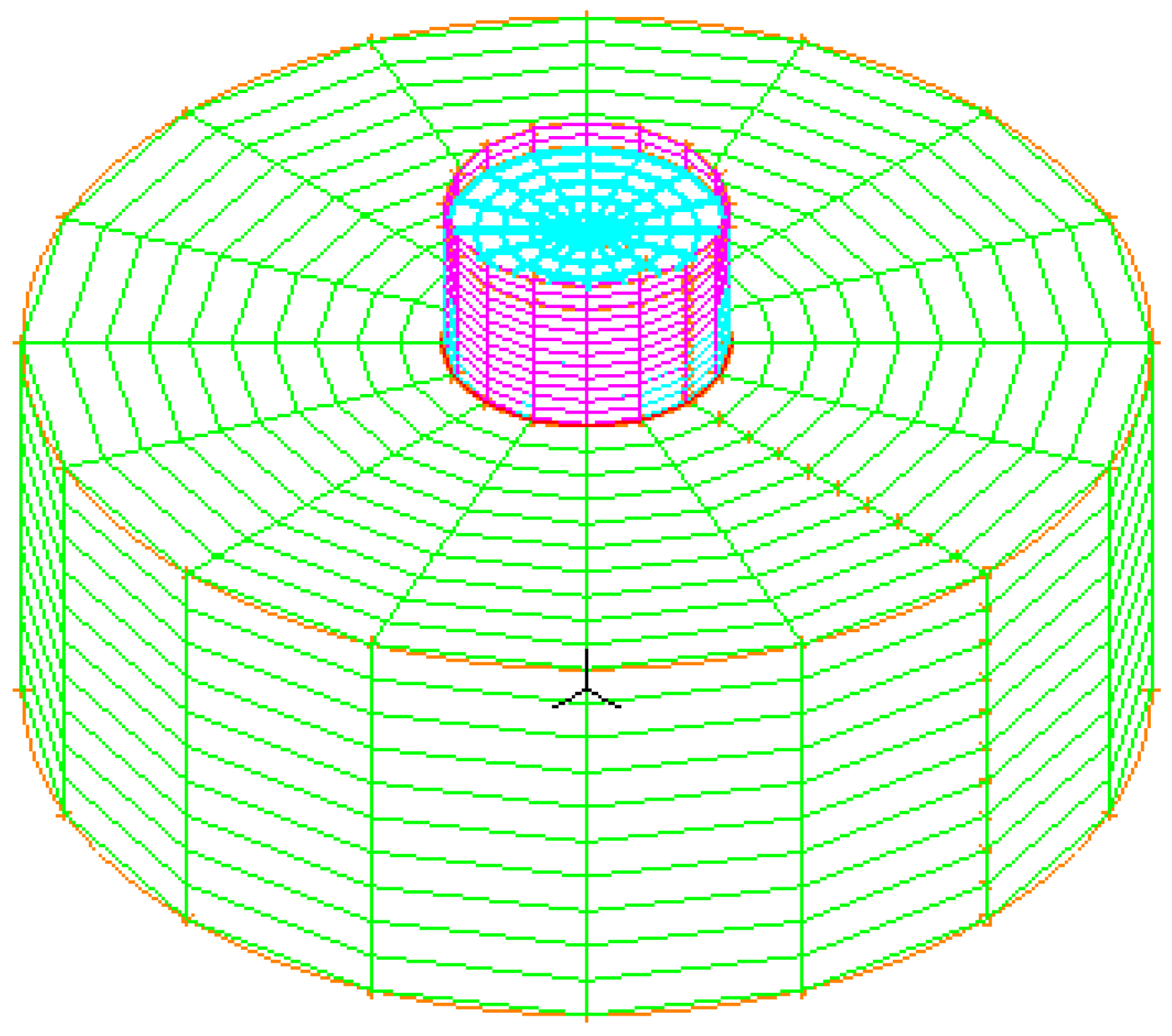
Figure 2.
The soil boundary conditions in static analysis.

Figure 3.
Acceleration-time history of the Loma Prieta Earthquake [20].
Figure 3.
Acceleration-time history of the Loma Prieta Earthquake [20].

Figure 4.
The effect of the tank diameter on the consolidation settlement.
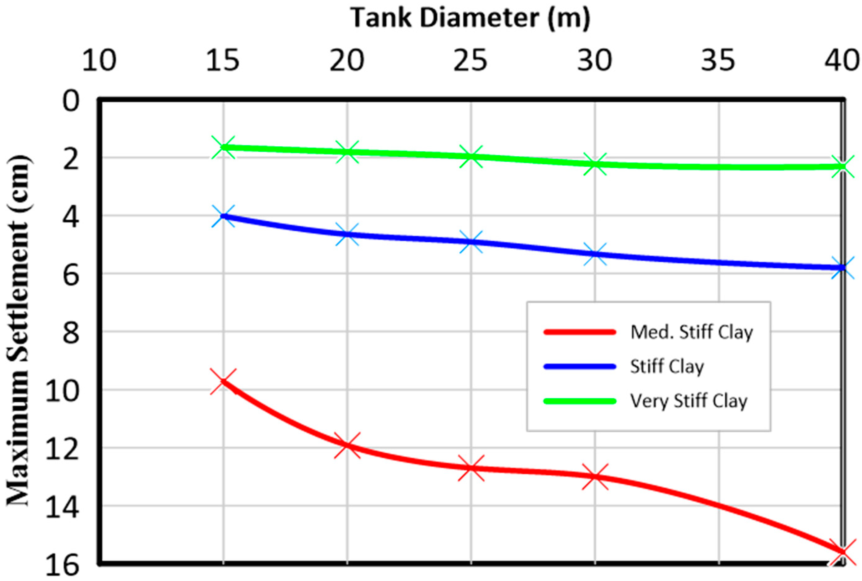
Figure 5.
Color contour shading of the consolidation settlement under the tank in the medium-stiff clay case.
Figure 5.
Color contour shading of the consolidation settlement under the tank in the medium-stiff clay case.
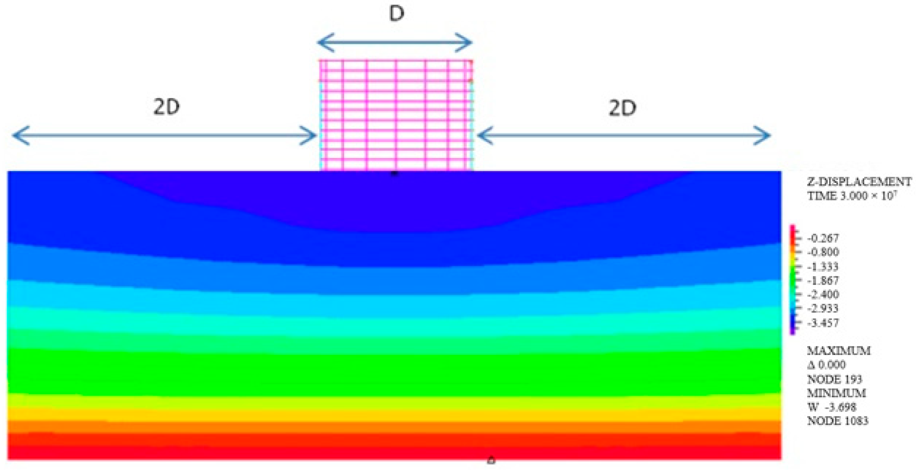
Figure 6.
Color contour shading of stress ZZ for the tank rested over medium-stiff clay.

Figure 7.
The additional stress results at different depths for different tank diameters in the case of stiff clay.
Figure 7.
The additional stress results at different depths for different tank diameters in the case of stiff clay.
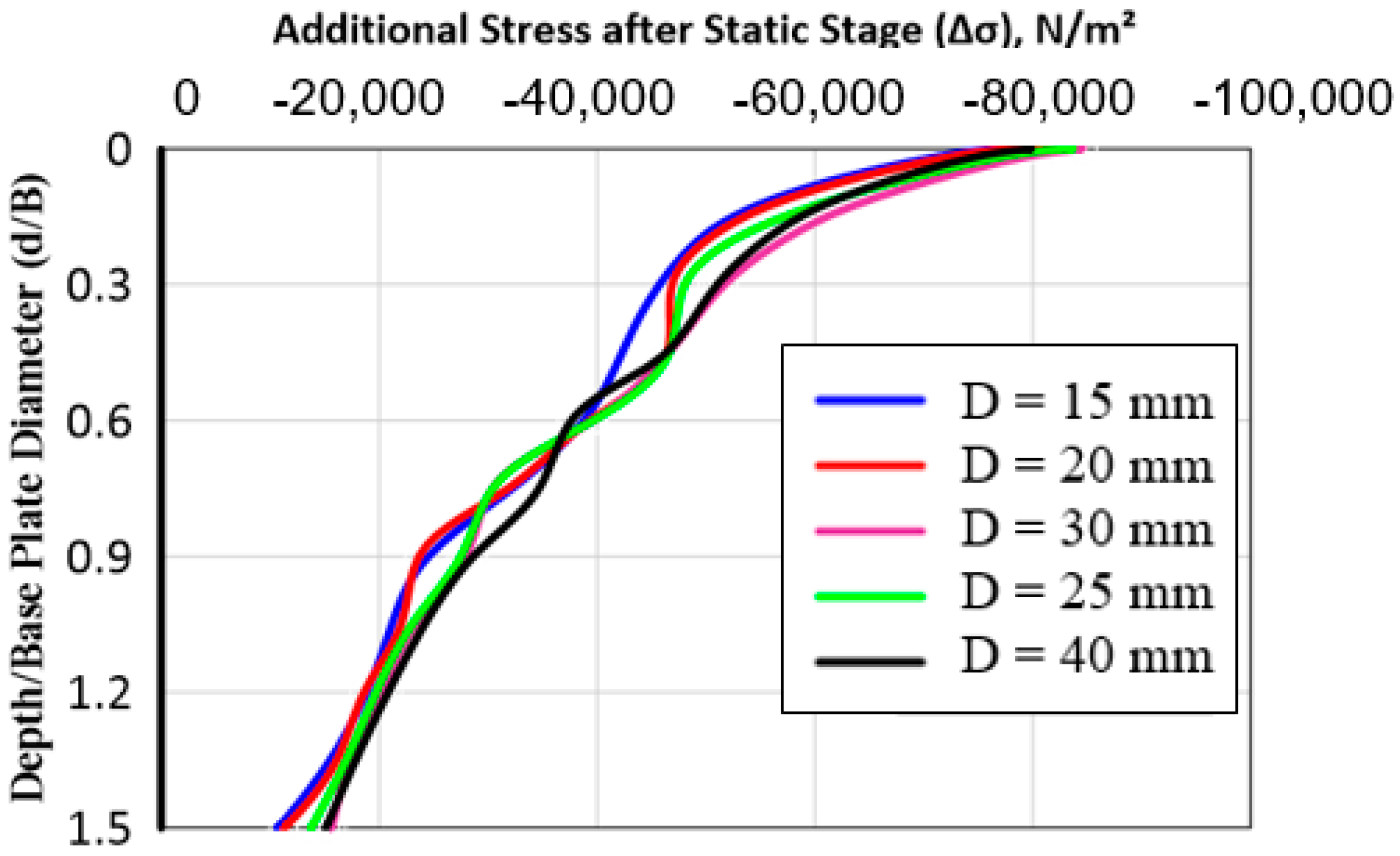
Figure 8.
The excess settlement under the tank during the earthquake for all cases.

Figure 9.
Variation of the dynamic settlement with time during the earthquake for tank 5 resting over medium-stiff clay and very stiff clay.
Figure 9.
Variation of the dynamic settlement with time during the earthquake for tank 5 resting over medium-stiff clay and very stiff clay.
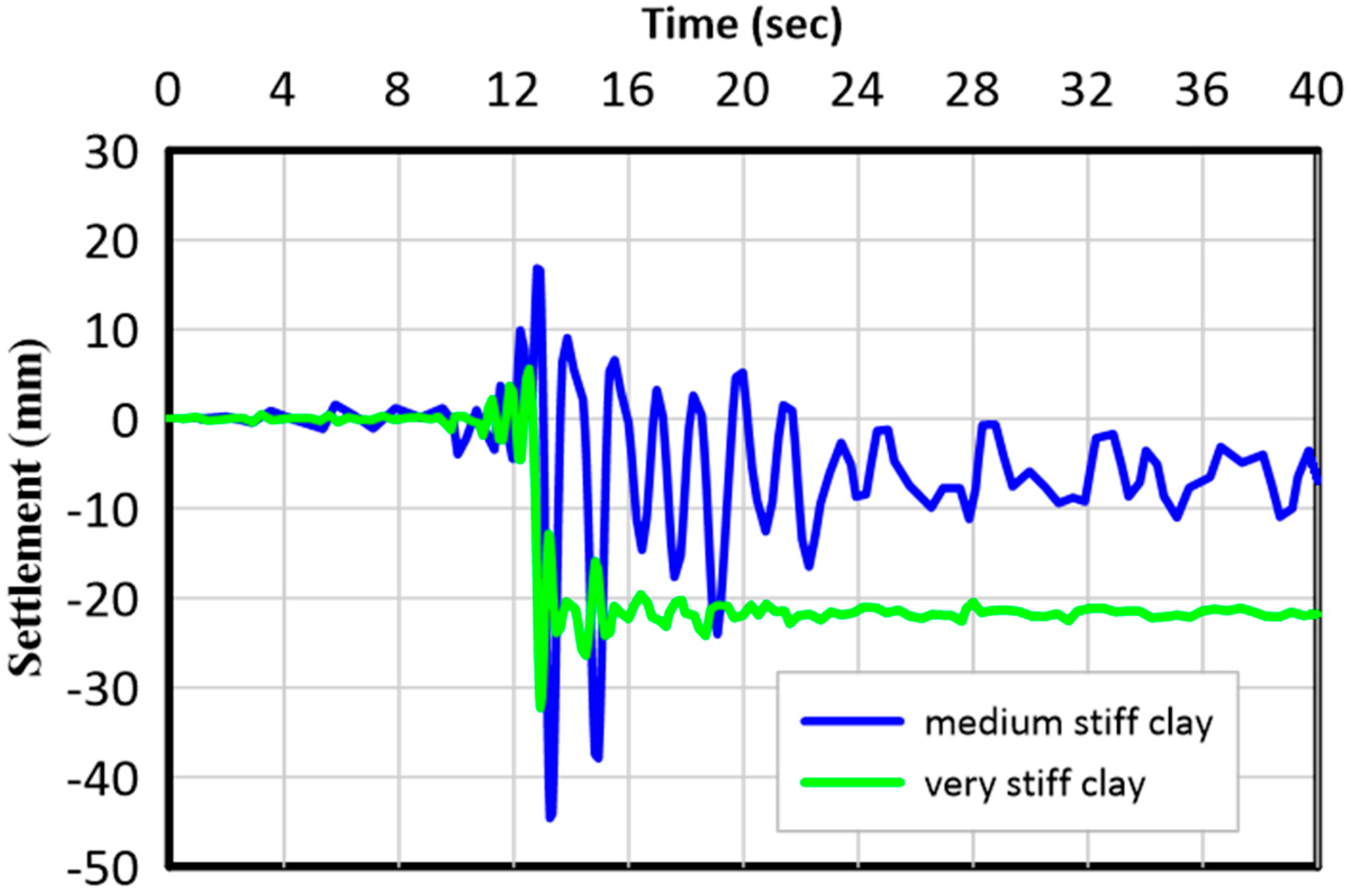
Figure 10.
Variation of the dynamic vertical stresses with time at a critical point located under the corner of the base plate for tank 4.
Figure 10.
Variation of the dynamic vertical stresses with time at a critical point located under the corner of the base plate for tank 4.
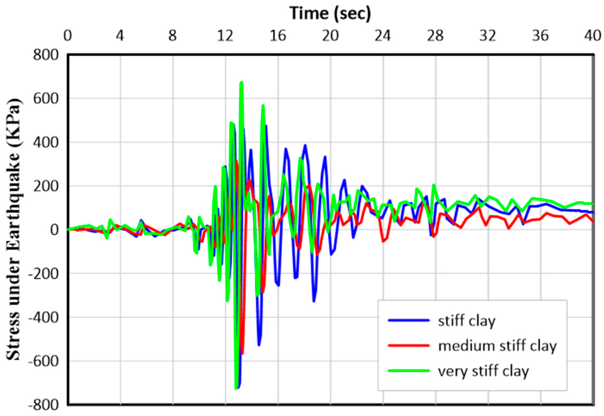
Figure 11.
Effect of the tank diameter on the peak vertical dynamic stresses.
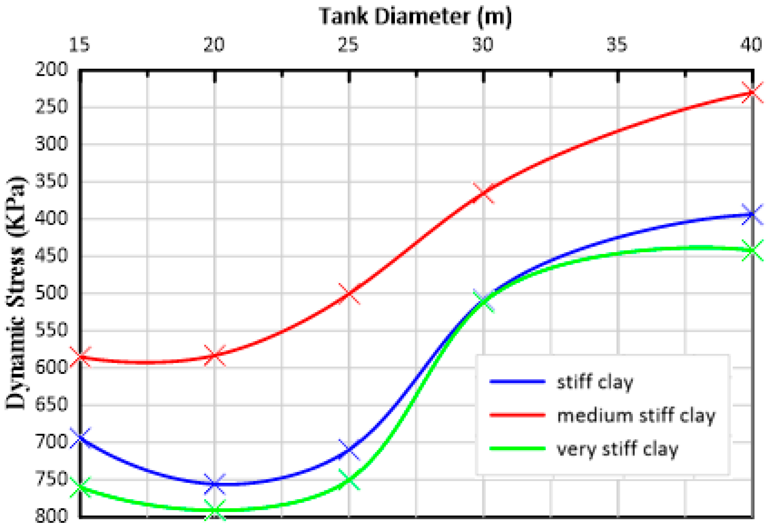
Figure 12.
The effect of the tank diameter on the maximum axial dynamic compression stress in the tank shell.
Figure 12.
The effect of the tank diameter on the maximum axial dynamic compression stress in the tank shell.
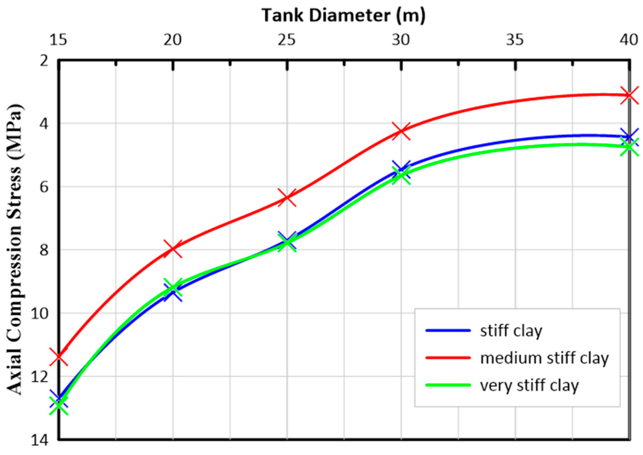
Figure 13.
Variation of the axial dynamic compression stresses with time at a critical point located under the tank shell for tank 3.
Figure 13.
Variation of the axial dynamic compression stresses with time at a critical point located under the tank shell for tank 3.


Table 1.
Properties of the used clay soils.
| Properties | Medium-Stiff Clay | Stiff Clay | Very Stiff Clay | Concrete | Steel |
| Poisson’s ratio, (Ʋ) | 0.40 | 0.40 | 0.40 | 0.20 | 0.29 |
| Unit weight, (Ƴ) kN/m3 | 17.0 | 19.0 | 20.0 | 25.0 | 78.0 |
| Elastic modulus, (E), MPa | 6.0 | 15.0 | 25.0 | 2 × 10⁴ | 2 × 10⁵ |
| Kappa (κ) | 0.017 | 0.01 | 0.0047 | - | - |
| Lambda (λ) | 0.088 | 0.043 | 0.023 | - | - |
Table 2.
Tank identification, geometries, and aspect ratio (H/D).
| Tank Identification | Tank Diameter, D (m) | Aspect Ratio, H/D | Shell Thickness, t (mm) | Bottom Plate Thickness, ta (mm) |
| 1 | 40 | 0.25 | 12 | 8 |
| 2 | 30 | 0.33 | 10 | 8 |
| 3 | 25 | 0.40 | 9 | 6 |
| 4 | 20 | 0.50 | 8 | 6 |
| 5 | 15 | 0.67 | 6 | 6 |
Disclaimer/Publisher’s Note: The statements, opinions and data contained in all publications are solely those of the individual author(s) and contributor(s) and not of MDPI and/or the editor(s). MDPI and/or the editor(s) disclaim responsibility for any injury to people or property resulting from any ideas, methods, instructions or products referred to in the content. |
© 2023 by the authors. Licensee MDPI, Basel, Switzerland. This article is an open access article distributed under the terms and conditions of the Creative Commons Attribution (CC BY) license (https://creativecommons.org/licenses/by/4.0/).
Share and Cite
MDPI and ACS Style
Salem, T.N.; El-Zohairy, A.; Abdelbaset, A.M. The Static and Dynamic Behavior of Steel Storage Tanks over Different Types of Clay Soil. CivilEng 2023, 4, 1169-1181. https://doi.org/10.3390/civileng4040064
AMA Style
Salem TN, El-Zohairy A, Abdelbaset AM. The Static and Dynamic Behavior of Steel Storage Tanks over Different Types of Clay Soil. CivilEng. 2023; 4(4):1169-1181. https://doi.org/10.3390/civileng4040064
Chicago/Turabian StyleSalem, Tarek N., Ayman El-Zohairy, and Ahmed M. Abdelbaset. 2023. "The Static and Dynamic Behavior of Steel Storage Tanks over Different Types of Clay Soil" CivilEng 4, no. 4: 1169-1181. https://doi.org/10.3390/civileng4040064